real-time stability management under stressed conditions: voltage … novosel & vahid... ·...
TRANSCRIPT
© PG&E and Quanta Technology LLC Proprietary and Confidential
Damir Novosel, Quanta
Vahid Madani, PG&E
Mevludin Glavic, Quanta
Amsterdam, October 2012
Real-time Stability Management Under
Stressed Conditions: Voltage Stability
Page 2 © PG&E and Quanta Technology LLC Proprietary and Confidential
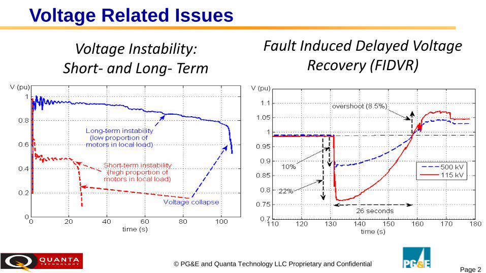
Voltage Related Issues
Voltage Instability: Short- and Long- Term
Fault Induced Delayed Voltage Recovery (FIDVR)

Page 3 © PG&E and Quanta Technology LLC Proprietary and Confidential
Inability to maintain voltage so that power and voltage
are controllable
• High system loading,
followed by a fault,
line overload or
generators hitting
excitation limits
• Grid gets overloaded, more
reactive power is consumed
and voltages drop
• Followed by motors stalling
Real
Power
Voltage
Margin
Pre-contingency case Post-contingency
case
PV Curve
108% Peak
- in 3 years
100% Peak
Margin
108% Peak
3 Wide Area Events: Voltage Instability
Page 4 © PG&E and Quanta Technology LLC Proprietary and Confidential
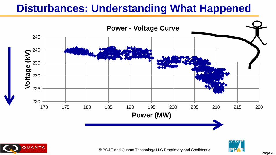
Disturbances: Understanding What Happened
220
225
230
235
240
245
170 175 180 185 190 195 200 205 210 215 220
Vo
ltag
e (
kV
)
Power (MW)
Power - Voltage Curve
Alarm when measured “PV-curve” slope approaches a critical level Source: Dmitry Kosterev, BPA
4
Page 5 © PG&E and Quanta Technology LLC Proprietary and Confidential
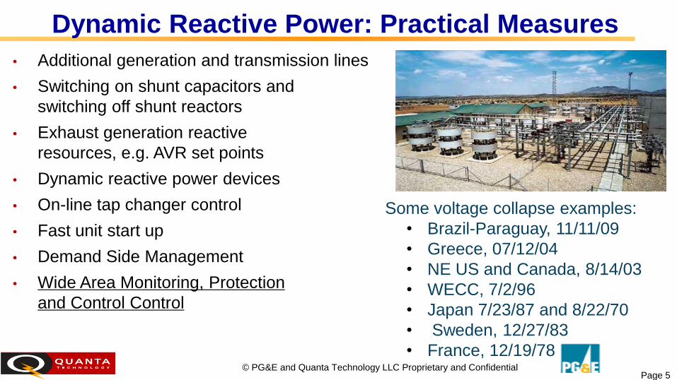
Dynamic Reactive Power: Practical Measures
• Additional generation and transmission lines
• Switching on shunt capacitors and
switching off shunt reactors
• Exhaust generation reactive
resources, e.g. AVR set points
• Dynamic reactive power devices
• On-line tap changer control
• Fast unit start up
• Demand Side Management
• Wide Area Monitoring, Protection
and Control Control
Some voltage collapse examples:
• Brazil-Paraguay, 11/11/09
• Greece, 07/12/04
• NE US and Canada, 8/14/03
• WECC, 7/2/96
• Japan 7/23/87 and 8/22/70
• Sweden, 12/27/83
• France, 12/19/78

Page 6 © PG&E and Quanta Technology LLC Proprietary and Confidential
Voltage Stability Monitoring & Assessment
Simple voltage-only measurements
Dynamic, model-based simulation tools
• Voltage Stability Assessment (VSA) based on State Estimation
contingency analysis
• Tracking the relative distance from voltage instability continually in
real-time:
Distance to the nose of the PV curve
State Estimation based stability boundary
• Important to validate model correctness
Measurement-based indicators
• Identify composite low voltage violations simultaneously over a broad
area
• Monitor available reactive power levels (capacitor/reactor reserves,
tap-changers)
• Distance of the load’s apparent impedance to the Thevenin
impedance
x Under-
voltage
signal
#1
#2
r
Voltage
instability
region #1: inaccurate under-voltage detection
#2: under-voltage fails to detect
Source: ABB

Page 7 © PG&E and Quanta Technology LLC Proprietary and Confidential
Measurement-Based Voltage Instability Detection
Simple, real time, voltage instability margin
detection, e.g. VIP*
Better than voltage-only methods, but simpler
than any other method • Much faster than EMS/SE contingency analysis
and not model dependent
Enabling tracking both slow changes and
system dynamics using PMUs (10-120
frames/s)
New Real-time Voltage Instability Indicator
(RVII) • Major improvements in accuracy, numerical
stability, implementation variants, and ease of use
Maximum power transfer
|Zapp | = |ZThev |
Point of collapse
* K. Vu and D. Novosel, “Voltage Instability Predictor (VIP) - Method
and System for Performing Adaptive Control to Improve Voltage
Stability in Power Systems,” US Patent No. 6,219,591, April 2001.
Z Thev Z app
Thevenin Load E

Page 8 © PG&E and Quanta Technology LLC Proprietary and Confidential
New RVII Advantages 1 (2)
Model-free, fast real-time voltage instability detection method*, independent of state
estimation
Implementation in several variants: bus, load center, transmission line, transmission
corridor
• Calculates Q-margin & other indices
for proximity to voltage collapse
• Stability boundary calculated with
real-time PMU data refresh rate
Easily combined with other
methods and indices
• Reactive power monitoring
• Could initiate model-based
contingency analysis,
e.g. by alarming the operator
New Q-margin Loading margin
Page 9 © PG&E and Quanta Technology LLC Proprietary and Confidential
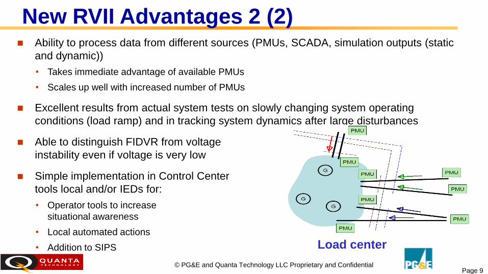
Ability to process data from different sources (PMUs, SCADA, simulation outputs (static
and dynamic))
• Takes immediate advantage of available PMUs
• Scales up well with increased number of PMUs
Excellent results from actual system tests on slowly changing system operating
conditions (load ramp) and in tracking system dynamics after large disturbances
Able to distinguish FIDVR from voltage
instability even if voltage is very low
Simple implementation in Control Center
tools local and/or IEDs for:
• Operator tools to increase
situational awareness
• Local automated actions
• Addition to SIPS
New RVII Advantages 2 (2)
Load center

Page 10 © PG&E and Quanta Technology LLC Proprietary and Confidential
Real-Life System Test Results
Alarm when measuring real-time Q margins
Realistic PQ-curve slope before and after the disturbance

Page 11 © PG&E and Quanta Technology LLC Proprietary and Confidential
Real-Time Simulation Results: PG&E Line switching – Two T-lines (Sequentially) Lines switched are from outside of the single line
The P-Q plane - Use of 5 PMUs for A-B Corridor
@ B
Reactive Margin Computation and Observability
- Time evolutions of margins for different PMUs
available
Page 12 © PG&E and Quanta Technology LLC Proprietary and Confidential
Comprehensive tests using real-life PMU and SCADA measurements and off-line
time-sequence simulation tools
Ability to detect instability even if voltage close to nominal
• Accurate results for load centers, transmission lines, and corridors
• Detection at highly-meshed high voltage systems (e.g. 500 kV) is more difficult
Results comparable to detailed, model-based off-line QV analysis; very
accurate closer to instability boundary
Discriminates between FIDVR and fast voltage instability
• FIDVR cases (no voltage collapse) are accurately detected despite the fact the
voltage is low for some time
No false alarms
Test Results

Page 13 © PG&E and Quanta Technology LLC Proprietary and Confidential
Deploy real-time application software based on RVII as part of
comprehensive WAMPAC system in control room
Design monitoring and control strategies based on RVII
Present and Future Activities
New
MEASUREMENT-BASED VOLTAGE STABILITY
Identification
RPM Methodology
Other Indices
Traditional
MODEL-BASED
VOLTAGE STABILITY Analysis
(EMS) SCADA
& Alarms WAMS
State Estimator
State Measurement
Other EMS Applications
New Applications
Small Signal Stability
Oscillation Monitoring
Transient & Voltage Stability
Stability Monitoring & Control
Island
Management
Island Detection,
Resynchronization,
& Blackstart
New Real-time Voltage Instability Indicator Solution
Alstom e-terravision
approach with new
RVII