real time target tracking with pan tilt zoom camera tim… · tracking with moving camera will run...
TRANSCRIPT
Real Time Target Tracking with Pan Tilt Zoom Camera
Pankaj Kumar, Anthony DickSchool of Computer ScienceThe University of Adelaide
Adelaide, AustraliaEmail: [email protected],
Tan Soo ShengElectrical and Computer Engineering
National University of SingaporeSingapore
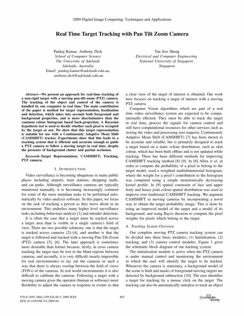
Abstract—We present an approach for real-time tracking ofa non-rigid target with a moving pan-tilt-zoom (PTZ) camera.The tracking of the object and control of the camera ishandled by one computer in real time. The main contributionof the paper is method for target representation, localisationand detection, which takes into account both foreground andbackground properties, and is more discriminative than thecommon colour histogram based back-projection. A Bayesianhypothesis test is used to decide whether each pixel is occupiedby the target or not. We show that this target representationis suitable for use with a Continuously Adaptive Mean Shift(CAMSHIFT) tracker. Experiments show that this leads to atracking system that is efficient and accurate enough to guidea PTZ camera to follow a moving target in real time, despitethe presence of background clutter and partial occlusion.
Keywords-Target Representation; CAMSHIFT; Tracking;PTZ camera;
I. INTRODUCTION
Video surveillance is becoming ubiquitous in many publicplaces including airports, train stations, shopping malls,and car parks. Although surveillance cameras are typicallymonitored manually, it is becoming increasingly commonfor some of the more mundane tasks to be performed auto-matically by video analysis software. In this paper, we focuson the task of tracking a person as they move about in anenvironment. This underlies many higher level surveillancetasks including behaviour analysis [1] and intruder detection.
It is often the case that a target must be tracked acrossa larger area than is visible in a single camera’s field ofview. There are two possible solutions: one is that the targetis tracked across cameras [2]–[4], and another is that thetarget is followed and tracked with a moving Pan-Tilt-Zoom(PTZ) camera [5], [6]. The later approach is sometimesmore desirable than former because, firstly, in cross cameratracking the target may be lost in the blind regions betweencameras, and secondly, it is very difficult (nearly impossiblefor real environments) to lay out the cameras in such away that there is always overlap between the field of views(FOVs) of the cameras. In real world environments it is alsodifficult to calibrate the cameras. Following a target with amoving camera gives the operator (human or software) moreflexibility to adjust the camera in response to events so that
a clear view of the target of interest is obtained. Our workhere focuses on tracking a target of interest with a movingPTZ camera.
Computer Vision algorithms which are part of a realtime video surveillance system are expected to be compu-tationally efficient. They must be able to track the targetin real time, process the signals for camera control andstill have computational resources for other services such asstoring the video and processing user requests. ContinuouslyAdaptive Mean Shift (CAMSHIFT) [7] has been shown tobe accurate and reliable, but is primarily designed to tracka target based on a static colour distribution, such as skincolour, which has been built offline and is not updated whiletracking. There has been different methods for improvingCAMSHIFT tracking method [8] [9]. In [8] Allen et al. inorder to compute the probability of a pixel to belong to thetarget model, used a weighted multidimensional histogram,where the weight for a pixel’s contribution to the histogramwas computed using a simple monotonically decreasingkernel profile. In [9] spatial constraint of face and upperbody and hence joint colour-spatial distribution was used toimprove over traditional CAMSHIFT tracking. We augmentCAMSHIFT to moving cameras by incorporating a novelway to obtain the target probability image. This is done byusing an improved model of the target and a model of itsbackground, and using Bayes theorem to compute the pixelweights for pixels which belong to the target.
A. Tracking System Overview
Our complete moving PTZ camera tracking system canbe divided into three basic modules; (1) Initialisation, (2)tracking, and (3) camera control modules. Figure 1 givesthe schematic block diagram of our tracking system.
The initialisation module is active when the PTZ camerais under manual control and monitoring the environmentin which the user will identify the target to be tracked.Whenever the camera is stationary, a background model ofthe scene is built and masks of foreground moving targets aredetected by background subtraction [10]. The user identifiesa target for tracking by a mouse click on the target. Thetracking can also be automatically initialise to track an object
2009 Digital Image Computing: Techniques and Applications
978-0-7695-3866-2/09 $26.00 © 2009 IEEE
DOI 10.1109/DICTA.2009.84
532
2009 Digital Image Computing: Techniques and Applications
978-0-7695-3866-2/09 $26.00 © 2009 IEEE
DOI 10.1109/DICTA.2009.84
424
2009 Digital Image Computing: Techniques and Applications
978-0-7695-3866-2/09 $26.00 © 2009 IEEE
DOI 10.1109/DICTA.2009.84
454
2009 Digital Image Computing: Techniques and Applications
978-0-7695-3866-2/09 $26.00 © 2009 IEEE
DOI 10.1109/DICTA.2009.84
492
Background Subtraction,Foreground Segmentation
Morphological Processing
User IdentifiesTarget for Tracking
Build Target andBackground Model
Compute weight for each Pixels in the Search Window
CAMSHIFT Localisationand Size Computation
Update Target and Background Model
Compute RelativePosition of Target to
Frame Center
Generate and Relay Camera Control Signalso that Frame Centre Moves Towards Target
Centre
Initialisation Module Tracking Module Camera Control Module
video stream from
Camera
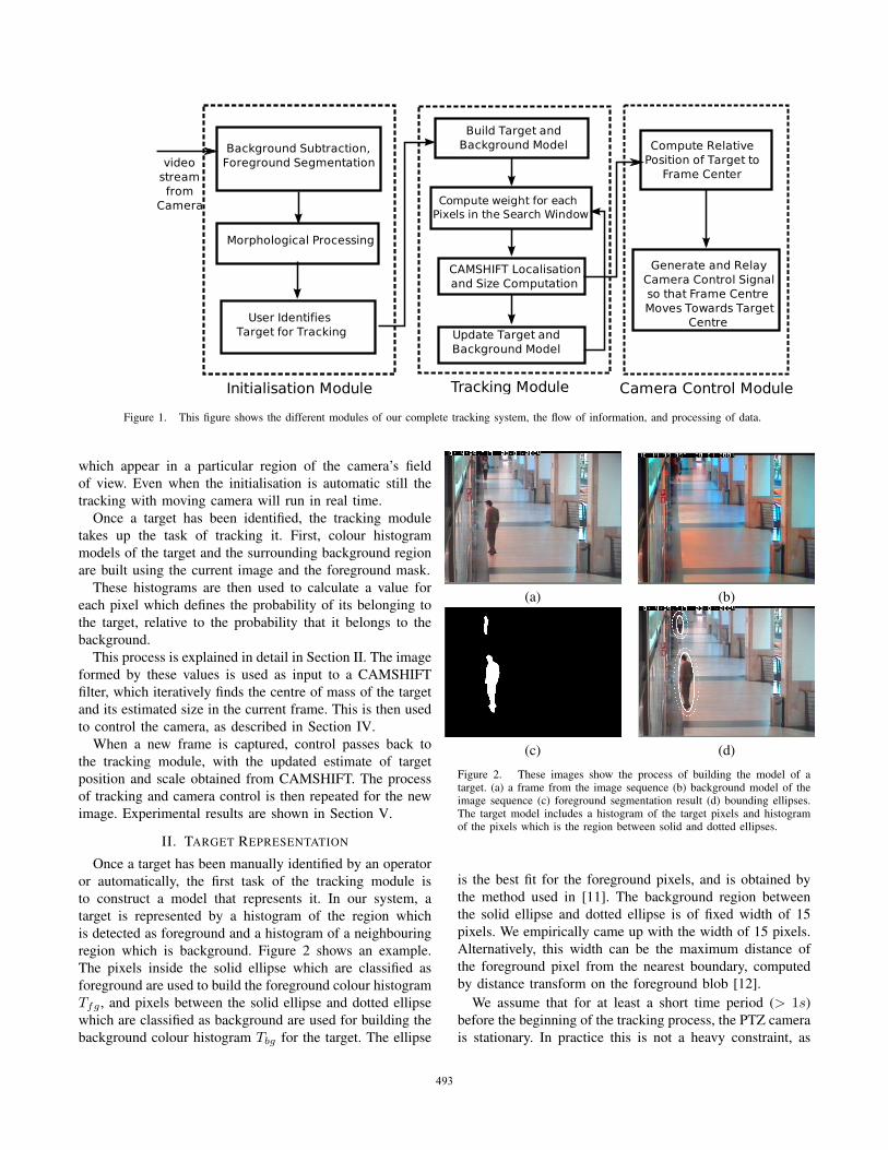
Figure 1. This figure shows the different modules of our complete tracking system, the flow of information, and processing of data.
which appear in a particular region of the camera’s fieldof view. Even when the initialisation is automatic still thetracking with moving camera will run in real time.
Once a target has been identified, the tracking moduletakes up the task of tracking it. First, colour histogrammodels of the target and the surrounding background regionare built using the current image and the foreground mask.
These histograms are then used to calculate a value foreach pixel which defines the probability of its belonging tothe target, relative to the probability that it belongs to thebackground.
This process is explained in detail in Section II. The imageformed by these values is used as input to a CAMSHIFTfilter, which iteratively finds the centre of mass of the targetand its estimated size in the current frame. This is then usedto control the camera, as described in Section IV.
When a new frame is captured, control passes back tothe tracking module, with the updated estimate of targetposition and scale obtained from CAMSHIFT. The processof tracking and camera control is then repeated for the newimage. Experimental results are shown in Section V.
II. TARGET REPRESENTATION
Once a target has been manually identified by an operatoror automatically, the first task of the tracking module isto construct a model that represents it. In our system, atarget is represented by a histogram of the region whichis detected as foreground and a histogram of a neighbouringregion which is background. Figure 2 shows an example.The pixels inside the solid ellipse which are classified asforeground are used to build the foreground colour histogramTfg , and pixels between the solid ellipse and dotted ellipsewhich are classified as background are used for building thebackground colour histogram Tbg for the target. The ellipse
(a) (b)
(c) (d)
Figure 2. These images show the process of building the model of atarget. (a) a frame from the image sequence (b) background model of theimage sequence (c) foreground segmentation result (d) bounding ellipses.The target model includes a histogram of the target pixels and histogramof the pixels which is the region between solid and dotted ellipses.
is the best fit for the foreground pixels, and is obtained bythe method used in [11]. The background region betweenthe solid ellipse and dotted ellipse is of fixed width of 15pixels. We empirically came up with the width of 15 pixels.Alternatively, this width can be the maximum distance ofthe foreground pixel from the nearest boundary, computedby distance transform on the foreground blob [12].
We assume that for at least a short time period (> 1s)before the beginning of the tracking process, the PTZ camerais stationary. In practice this is not a heavy constraint, as
533425455493
the user is unlikely to select a target while the camera ismoving. Thus we can obtain a background model of thescene Figure 2(b) and a segmentation of the moving targetas shown in Figure 2(c). Figure 2(d) shows the boundingellipses for foreground region and background region.
A target’s foreground model Tfg is a N -bin histogram,which is non-parametric colour probability distribution func-tion (pdf) of the target foreground. Similarly the target’sbackground model is another N -bin histogram.
Tfg = qfgu Nu=1, where
N∑u=1
qfgu = 1
Tbg = qbgu Nu=1, where
N∑u=1
qbgu = 1 (1)
Let the function which associates bin index u to the colourvector at pixel location xi, i = 1...nfg where nfg is thetotal number of pixels in the target foreground, be denotedby b(xi) ∈ 1, ..., N. The probability of the colour featureu = 1, ..., N in the target foreground is then computed as
qfgu = Cfg
nfg∑i=1
wfgi δ[b(xi), u]. (2)
Here, δ is the kronecker delta function which is 1 whenb(xi) = u and zero otherwise, and Cfg is the normalisingconstant such that
∑Nu=1 q
fgu = 1. The term wi is a weight
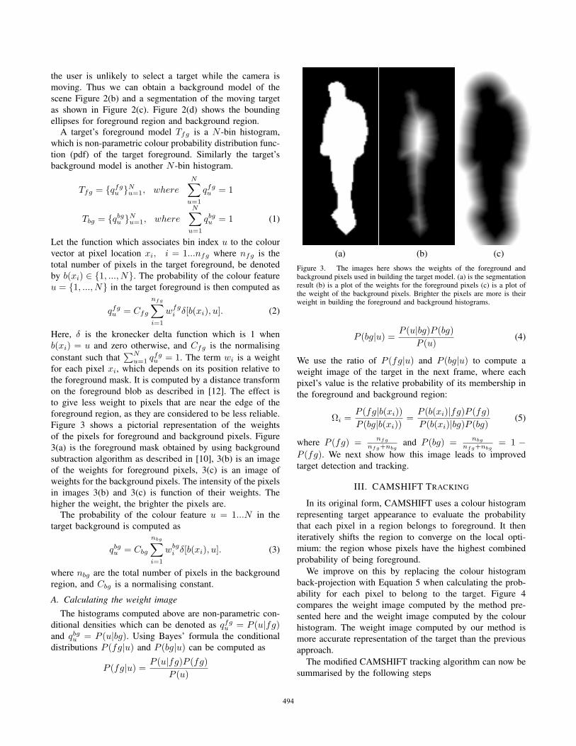
for each pixel xi, which depends on its position relative tothe foreground mask. It is computed by a distance transformon the foreground blob as described in [12]. The effect isto give less weight to pixels that are near the edge of theforeground region, as they are considered to be less reliable.Figure 3 shows a pictorial representation of the weightsof the pixels for foreground and background pixels. Figure3(a) is the foreground mask obtained by using backgroundsubtraction algorithm as described in [10], 3(b) is an imageof the weights for foreground pixels, 3(c) is an image ofweights for the background pixels. The intensity of the pixelsin images 3(b) and 3(c) is function of their weights. Thehigher the weight, the brighter the pixels are.
The probability of the colour feature u = 1...N in thetarget background is computed as
qbgu = Cbg
nbg∑i=1
wbgi δ[b(xi), u]. (3)
where nbg are the total number of pixels in the backgroundregion, and Cbg is a normalising constant.
A. Calculating the weight imageThe histograms computed above are non-parametric con-
ditional densities which can be denoted as qfgu = P (u|fg)
and qbgu = P (u|bg). Using Bayes’ formula the conditional
distributions P (fg|u) and P (bg|u) can be computed as
P (fg|u) =P (u|fg)P (fg)
P (u)
(a) (b) (c)Figure 3. The images here shows the weights of the foreground andbackground pixels used in building the target model. (a) is the segmentationresult (b) is a plot of the weights for the foreground pixels (c) is a plot ofthe weight of the background pixels. Brighter the pixels are more is theirweight in building the foreground and background histograms.
P (bg|u) =P (u|bg)P (bg)
P (u)(4)
We use the ratio of P (fg|u) and P (bg|u) to compute aweight image of the target in the next frame, where eachpixel’s value is the relative probability of its membership inthe foreground and background region:
Ωi =P (fg|b(xi))P (bg|b(xi))
=P (b(xi)|fg)P (fg)P (b(xi)|bg)P (bg)
(5)
where P (fg) = nfg
nfg+nbgand P (bg) = nbg
nfg+nbg= 1 −
P (fg). We next show how this image leads to improvedtarget detection and tracking.
III. CAMSHIFT TRACKING
In its original form, CAMSHIFT uses a colour histogramrepresenting target appearance to evaluate the probabilitythat each pixel in a region belongs to foreground. It theniteratively shifts the region to converge on the local opti-mium: the region whose pixels have the highest combinedprobability of being foreground.
We improve on this by replacing the colour histogramback-projection with Equation 5 when calculating the prob-ability for each pixel to belong to the target. Figure 4compares the weight image computed by the method pre-sented here and the weight image computed by the colourhistogram. The weight image computed by our method ismore accurate representation of the target than the previousapproach.
The modified CAMSHIFT tracking algorithm can now besummarised by the following steps
534426456494

(a) (b) (c)Figure 4. The images here shows (a) the frame in which the weight imagefor the target closure to the camera is computed (b) colour probabilityimage computed using histogram back-projection as used in [7] (c) theweight image computed by the method proposed here. Pixel intensity isproportional to probability of belonging to foreground. The weight image(c) is a more accurate representation of the target in frame (a) than thecolour probability image (b).
1) Initial location of the 2D mean shift search windowis based on the bounding box of the foreground-background segmentation blob of the target.
2) Compute the weight image of the 2D region centred atthe search window location and the surrounding area,using Equation 5.
3) Use mean-shift to converge to the new location of thetarget. Store the zeroth moment and mean location.
4) Threshold the weight image to obtain a binary fore-ground/background mask for the target. Use this toupdate the foreground and background colour his-tograms. Note that this works whether the camera isstatic or moving.
5) In the next image frame the search window is centredat the new target location, and its size is the function ofzeroth moment. The process is again repeated startingfrom step 2.
The foreground and background histograms are updatedusing a learning factor βfg and βbg , respectively. The valueof βfg and βbg is empirically chosen and it depends uponthe nature of lighting in the environment and environmentitself, which determines the rate at which the model ofthe foreground and background will change. Usually βbg isgreater than βfg . For a moving camera background modelwill change faster than foreground model of the target.
T kfg = (1− βfg)T k−1
fg + βfg × T localisedfg
T kbg = (1− βbg)T k−1
bg + βbg × T localisedbg (6)
where k is the current frame and T localisedfg , T localised
bg are theforeground and background models for the target localisedin the current frame.
IV. CAMERA CONTROL
The aim of the camera control unit is to generate and relaycontrol commands to the camera such that the target centre
R5 R4 R3
R2R1R6
R7 R8 R9
Figure 5. This figure illustrates the working of the camera control module.The aim of the camera control module is to keep the target centre in theregion R1. The target centre by localisation can be found in any of theregions ranging from R1...R9. According to the region in which the targetcentre is found Pan or tilt or both commands are generated and send to thecamera depending upon the last sent command.
lies in the region “R1” of the frame as shown in Figure 5.
In every frame, the horizontal and vertical distance of thetarget from the frame centre in region “R1” is calculated. Ifthe horizontal or vertical distances or both are greater than athreshold then commands are generated by giving priority tothe distance which is greater. If vertical distance is greaterthan horizontal then tilt command is given priority over panand vice-versa. If the target centre lies in “R1” region ie thehorizontal and vertical distances are within threshold thenstop command is send to the camera.
One concern in the design of a camera control procedureis to minimise the delay of the camera in executing com-mands. Different PTZ cameras have different amounts oflag; the camera which we used had a delay of approximately100 ms in executing commands. To reduce the loss of timein transmission and execution of commands, the programkeeps a record of the command the camera is executing.Hence, repeated commands will be avoided to reduce delays.For example if the target centre is in region “R2” thencommand for right panning is generated and checked againstthe last command send to the camera. If the last commandis different from pan-right then first a stop command issend and after a delay of 100 ms the pan-right commandis send. But if the last command is same as pan-right thenno command is send to the camera which saves 200 ms oftime. This is important from a tracking point of view asthe speed of the target which the camera can track dependsmore on this factor, than on the computation required fortracking.
535427457495

V. RESULTS
We show three sets of tracking results of the several oth-ers, were the proposed PTZ camera tracker has been able tosuccessfully track the identified individual with the movingcamera. These sequences have been captured using a screencapture software while running the tracking implementationon the same computer. This is worth mentioning to showthe computational efficiency of the proposed algorithm. Theframe size of the frames processed by the tracking algorithmis 352×255 and all the 25 frames in a second are processedwithout 100% use of the CPU on a 3.0 G-Hz Pentiummachine.
Due to the latency of the camera in executing instructions,in tracking results the camera centre lags behind the targetcentre when it is moving quickly. However, it recovers whenthe target slows down or stops. This is due to the slowprocessing of the commands by the PTZ camera and notdue to the tracking algorithm.
In the results shown in Figure 6 there are instances ofillumination changes, highlights and change of target pose.This tracking image sequence is 2980 frames long. Thetracker has been successfully able to handle changes in thetarget and background. Some times the camera centre is notexactly on the target centre and lags behind the target centredue to the latency of the camera in executing the commandssent to it. This problem can be avoided by using a PTZcamera whose response to commands are faster.
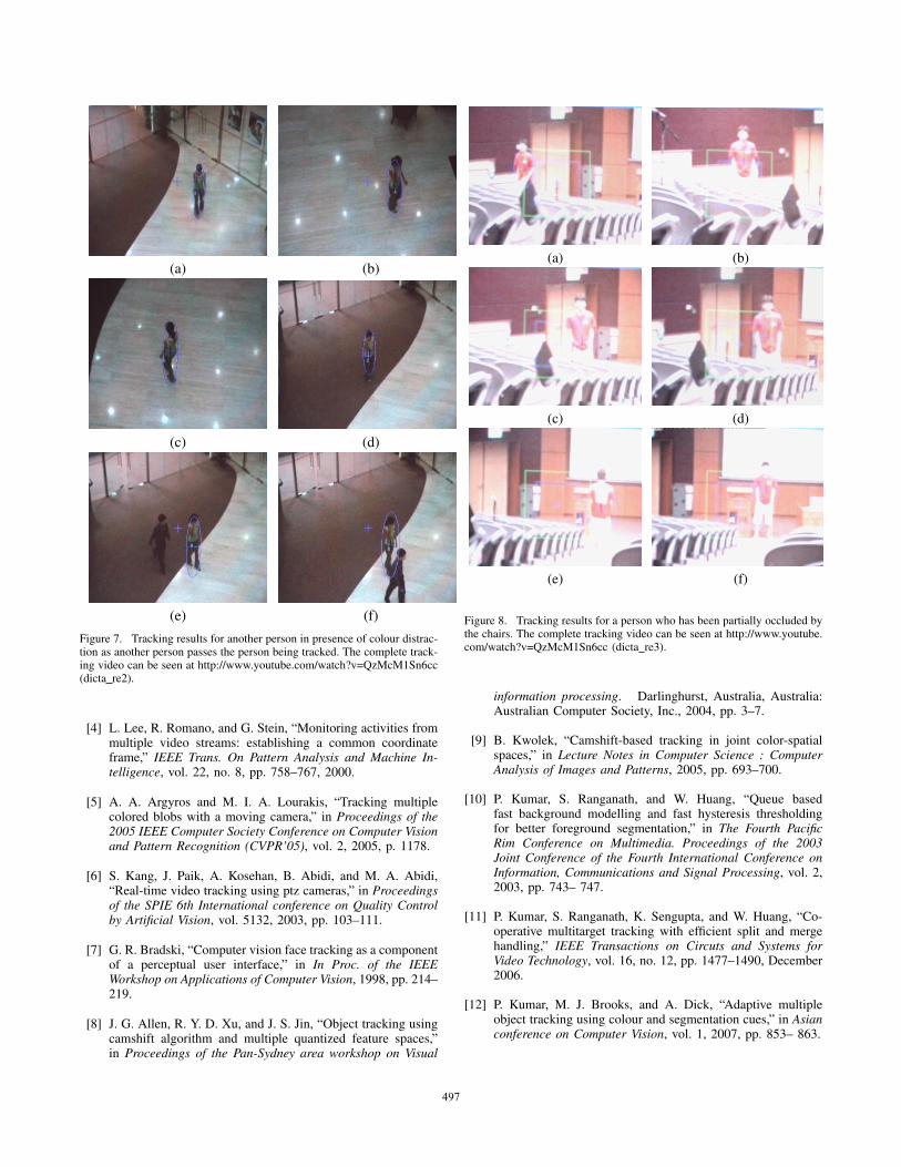
Figure 7 shows tracking results for another person in thesame scenario as Figure 6. In this case there are multiplemoving targets which can potentially distract the tracker.As seen in Figure 7 (e) (f) the representation of the targetis robust enough to continue tracking even in presence ofthese distractions. The length of this tracking sequence is2814 frames.
Figure 8 shows successful tracking results in presence ofpartial occlusion. The target in a lecture theatre environmenthas been tracked in spite of being partially occluded by thechairs.
VI. SUMMARY AND IDEAS FOR FUTURE WORK
In this paper a robust target representation and detectionmethod has been proposed, based on distance transform ofthe segmented target and application of Bayes theorem to theprobability distribution of the foreground pixels and back-ground pixels in the neighbourhood of the target. Severaltracking videos demonstrate the efficacy of the novel targetrepresentation in tracking a target with a moving PTZ cam-era. The target representation and hence localisation is betterthan the previously used histogram back-projection method.The representation and detection is also robust to distractionsand partial occlusions. Some times the target representationis vulnerable to large scale illumination changes, which canbe improved by a using colour space which is more robustto illumination changes. The vulnerability to illumination
(a) (b)
(c) (d)
(e) (f)
Figure 6. Successful tracking of a person with moving PTZ camera.There are instances of illumination change and background change. Thecomplete tracking video can be seen at http://www.youtube.com/watch?v=QzMcM1Sn6cc (dicta re1).
change can also be ameliorated by using multiple cue indetection of the target. It would be interesting to extendthis method to multiple target tracking, which adds the extraproblem of deciding who the camera will follow in case ofclashes. Use of particle filter instead of CAMSHIFT filterwhich is more robust in tracking multiple targets can alsobe explored.
REFERENCES
[1] P. Kumar, S. Ranganath, W. Huang, and K. Sengupta, “Frame-work for real time behavior interpretation from traffic video,”IEEE Transactions on Intelligent Transportation Systems,vol. 6, no. 1, pp. 43–53, 2005.
[2] A. Chilgunde, P. Kumar, S. Ranganath, and H. Weimin,“Multi-camera target tracking in blind regions of cameraswith non-overlapping fields of view,” in Proceedings ofBritish Machine Vision Conference, 2004, pp. 397–406.
[3] O. Javed, Z. Rasheed, K. Shafique, and M. Shah, “Trackingacross multiple cameras with disjoint views,” in Proceedingsof Ninth IEEE International Conference on Computer Vision,vol. 2, 2003, pp. 952–957.
536428458496
(a) (b)
(c) (d)
(e) (f)Figure 7. Tracking results for another person in presence of colour distrac-tion as another person passes the person being tracked. The complete track-ing video can be seen at http://www.youtube.com/watch?v=QzMcM1Sn6cc(dicta re2).
[4] L. Lee, R. Romano, and G. Stein, “Monitoring activities frommultiple video streams: establishing a common coordinateframe,” IEEE Trans. On Pattern Analysis and Machine In-telligence, vol. 22, no. 8, pp. 758–767, 2000.
[5] A. A. Argyros and M. I. A. Lourakis, “Tracking multiplecolored blobs with a moving camera,” in Proceedings of the2005 IEEE Computer Society Conference on Computer Visionand Pattern Recognition (CVPR’05), vol. 2, 2005, p. 1178.
[6] S. Kang, J. Paik, A. Kosehan, B. Abidi, and M. A. Abidi,“Real-time video tracking using ptz cameras,” in Proceedingsof the SPIE 6th International conference on Quality Controlby Artificial Vision, vol. 5132, 2003, pp. 103–111.
[7] G. R. Bradski, “Computer vision face tracking as a componentof a perceptual user interface,” in In Proc. of the IEEEWorkshop on Applications of Computer Vision, 1998, pp. 214–219.
[8] J. G. Allen, R. Y. D. Xu, and J. S. Jin, “Object tracking usingcamshift algorithm and multiple quantized feature spaces,”in Proceedings of the Pan-Sydney area workshop on Visual
(a) (b)
(c) (d)
(e) (f)
Figure 8. Tracking results for a person who has been partially occluded bythe chairs. The complete tracking video can be seen at http://www.youtube.com/watch?v=QzMcM1Sn6cc (dicta re3).
information processing. Darlinghurst, Australia, Australia:Australian Computer Society, Inc., 2004, pp. 3–7.
[9] B. Kwolek, “Camshift-based tracking in joint color-spatialspaces,” in Lecture Notes in Computer Science : ComputerAnalysis of Images and Patterns, 2005, pp. 693–700.
[10] P. Kumar, S. Ranganath, and W. Huang, “Queue basedfast background modelling and fast hysteresis thresholdingfor better foreground segmentation,” in The Fourth PacificRim Conference on Multimedia. Proceedings of the 2003Joint Conference of the Fourth International Conference onInformation, Communications and Signal Processing, vol. 2,2003, pp. 743– 747.
[11] P. Kumar, S. Ranganath, K. Sengupta, and W. Huang, “Co-operative multitarget tracking with efficient split and mergehandling,” IEEE Transactions on Circuts and Systems forVideo Technology, vol. 16, no. 12, pp. 1477–1490, December2006.
[12] P. Kumar, M. J. Brooks, and A. Dick, “Adaptive multipleobject tracking using colour and segmentation cues,” in Asianconference on Computer Vision, vol. 1, 2007, pp. 853– 863.
537429459497