real time uav altitude, attitude and motion estimation...
TRANSCRIPT

Noname manuscript No.(will be inserted by the editor)
Real time UAV Altitude,Attitude and MotionEstimation from HybridStereovision.
Damien Eynard and
Pascal Vasseur and
Cedric Demonceaux
and Vincent Fremont
Received: date / Accepted: date
Abstract Knowledge of altitude, attitude and motion
is essential for an Unmanned Aerial Vehicle during crit-
ical maneuvers such as landing and take-off. In this
paper we present a hybrid stereoscopic rig composed
of a fisheye and a perspective camera for vision-based
navigation. In contrast to classical stereoscopic systems
based on feature matching, we propose methods which
avoid matching between hybrid views. A plane-sweeping
approach is proposed for estimating altitude and de-
tecting the ground plane. Rotation and translation are
then estimated by decoupling: the fisheye camera con-
tributes to evaluating attitude, while the perspective
camera contributes to estimating the scale of the trans-
lation. The motion can be estimated robustly at the
scale, thanks to the knowledge of the altitude.
We propose a robust, real-time, accurate, exclusively
vision-based approach with an embedded C++ imple-
D. EynardMIS Laboratory, 7, rue du moulin neuf - University of Pi-cardie Jules Verne, Amiens, FranceTel.: +333-22-827663Fax: +333-22-827618E-mail: [email protected]
P. VasseurLITIS Laboratory, University of Rouen, Saint-Etienne-du-Rouvray, FranceE-mail: [email protected]
C. DemonceauxLe2i Laboratory - UMR CNRS 5158, University of Burgundy,Le Creusot, FranceE-mail: [email protected]
V. FremontHeudiasyc Laboratory of University of Technology ofCompiegne, FranceE-mail: [email protected]
mentation. Although this approach removes the need
for any non-visual sensors, it can also be coupled with
an Inertial Measurement Unit.
Keywords UAV · hybrid stereovision · motion ·attitude · altitude
1 Introduction
Unmanned Aerial Vehicles (UAV) have received a lot of
attention over the last decade, in relation to command
and on-board computer vision. Interest in these top-
ics has focused largely on increasing UAV autonomy,
which includes maneuvers such as landing and take-off.
In this context a fast, robust, accurate estimation of
critical parameters such as altitude, attitude, motion
and velocity is clearly crucial for the control loop.
A number of sensors have been used to estimate
these parameters. Altitude can be determined by GPS,
altimeter, radar, or laser. Attitude can be provided by
Inertial Measurement Unit (IMU), and motion by GPS
or radar. Raw Global Positioning Systems (GPS) have
a poor accuracy both vertically (accuracy between 25
and 50 meters) and horizontally (less than 15 meters).
Moreover, GPS is sensitive to interruptions in transmis-
sion in urban environments. Radar can estimate both
altitude and velocity with greater accuracy, but it re-
quires active sensors that consume power. Altimeters
are very widely used, but they depend on pressure vari-
ations, which implies an accuracy error of between 6%
and 7%. Laser altimeters, on the other hand, are highly
accurate, but they have very specific requirements con-
cerning reflecting surfaces. Finally, IMU can provide
indications of velocity, acceleration, attitude and orien-
tation, but it is subject to drift and error accumulation.
As an alternative to these sensors, vision-based sys-
tems, thanks to the growth of computational capacity,
can now rapidly estimate all these parameters, as well
as performing other visual tasks. Furthermore, cameras
remain compact, passive systems with correspondingly
low energy consumption, and can provide information
at high rates (up to 200Hz).
Most of the works using computer vision for UAV
are based on the optical flow analysis obtained with
a single camera Barrows et al. (2001); Beyeler et al.
(2006); Chahl et al. (2004); Green et al. (2003). In-
deed, optical flow can be efficiently computed and con-
sequently embedded for navigation purpose. These sys-
tems were bio-inspired by information processing mech-
anisms that have evolved in bees, and consist in de-
ducing the altitude according to the optical flow, given
knowledge of the camera’s motion. Beyeler et al. (2006)
is alone in proposing an estimation of pitch to cor-

2 Damien Eynard and Pascal Vasseur and Cedric Demonceaux and Vincent Fremont
rect the optical flow, without which an unstable system
might result. An original approach using a single per-
spective camera is to be found in Cheriany et al. (2009).
The authors use a technique based on the learning of
a mapping between texture information contained in a
top-down aerial image and altitude values. This learn-
ing stage is performed over different kinds of terrain,
and a spatio-temporal Markov Random Field is used.
However, optical flow information is clearly not suffi-
cient for a complete control of a UAV.
2 Related Work
As explained before, orientation and position parame-
ters are essential for the control of the UAV and vision
based methods can be very interesting because of the
richness of the provided information. A hierarchy be-
tween these parameters can be established according
to their importance in the control loop. The most im-
portant one deals with the attitude knowledge for the
stabilization followed by the altitude for hovering and
landing maneuvers and finally position and yaw angle
for trajectory. Consequently, this ranking imposes the
refreshing rate requirement for the control. In this work,
even if we do not manage the control of the UAV, our
aim is to propose a complete onboard vision system able
to provide orientation and position parameters at the
required frequency rate for a future loop control. Many
works based on vision solely or vision fused with other
sensors have been already proposed. A complete recent
review is presented in Weiss et al. (2011). These works
can be divided in two categories which are respectively
based on cameras placed in the environment or based
on embedded cameras on the UAV. The former con-
sists generally in a fixed camera network that supervises
completely a 3D scene. The most well known system is
Vicon and has been successfully employed in UAV con-
trol Mellinger et al. (2011). Such systems are particu-
larly efficient with a high measure frequency, very ac-
curate with no drift and also robust. However, the fixed
configuration does not allow any exploration of a new
and unknown environment. The second category deals
with onboard camera and can also be divided according
to two sections. The first one is based on the use of a
known pattern placed in the environment. In Garcia-
pardo et al. (2000); Saripalli et al. (2002); Sharp et al.
(2001), the authors make use of a downward-pointing
perspective camera to estimate altitude according to a
predefined pattern laid out on the ground. Recently, a
circular pattern has been used in order to measure the
pose of a UAV Eberli et al. (2011). This kind of ap-
proach is interesting, since it requires only one camera,
provides a complete pose and can be used in real time.
This solution is the complementary of Vicon approach
since the camera looks an a priori known environment
while with Vicon, cameras of the environment tracks
a known pattern placed on the UAV. The advantages
and drawbacks are then similar. The other solution con-
sists of onboard cameras that capture and treat data
from an unknown and unstructured environment (no
artificial landmark). In this way, it is possible to es-
timate orientation and position according to features
detected in the environment. If some absolute features
such as horizon, vertical direction or ground are used,
it is then possible to perform the estimation in an ab-
solute reference frame and to obtain absolute measures
of attitude and altitude. For example to estimate the
attitude from horizon line, Demonceaux et al. (2006)
propose a method based on an omnidirectional view
while Dusha et al. (2007) use a perspective camera.
Thurrowgood et al. (2009) estimates the attitude using
a fast histogram based method which can be adapted
for any type of camera. For a complete absolute six
degrees of freedom estimation, an initial geo-localized
reference is then necessary. If used features have no par-
ticular identity, the orientation and position estimation
is performed relatively to the structure formed by these
features. Such methods (SLAM, SFM, Visual Odome-
try, ego-motion) are now well-known and many different
algorithms have been already proposed successfully in
Davison et al. (2007); Hartley and Zisserman (2004);
Nister (2004). Then, works of Li et al. (2008); Pless
(2003) can determine the motion from non-overlapping
cameras. Nevertheless they need a least of 14-points or
17-points to retrieve the motion that increases the com-
putation time and noise sensitivity. However, if these
methods are generally well adapted for mobile robots
or vehicles, a direct transfer to micro-aerial vehicles is
not possible and requires specific adaptations and de-
velopments Lee et al. (2010). Since most of the efficient
methods are based on feature points, a possible adap-
tation consists in including some a priori knowledges
or hypotheses in order to reduce the number of nec-
essary points. In Kalantari et al. (2011), Fraundorfer
et al. (2010), Naroditsky et al. (2011), the authors pro-
pose a relative pose estimation between two views by a
three-plus-one algorithm, based on the correspondence
of three points, given a common direction in the two
views. This common direction can then be obtained by
IMU for example. A recent work proposed also to use
only one point for structure from motion Scaramuzza
(2011). However, the used constraint for reducing the
number of points is only valid for mobile robots.
The most recent and successful autonomous micro-
aerial vehicle based on vision with adapted methods is
described in Blosch et al. (2010); Weiss et al. (2011).

Real time UAV Altitude, Attitude and Motion Estimation from Hybrid Stereovision. 3
The authors propose a monocular Simultaneous Local-
ization and Mapping (SLAM) framework from which
they extract pose parameters for a complete control of
the six degrees of freedom. The use of a SLAM approach
allows to correct the possible drift by loop closing. Since
their system is based on a single wide field of view cam-
era, the depth information can not be directly recov-
ered. This is why they propose the initialization of the
map scale by hand and maintain the consistency of this
scale by fusing IMU data and camera poses through
an EKF Nutzi et al. (2011). The complete pose from
the SLAM is computed at 15-30 Hz and the compar-
ison of results with a VICON shows the effectiveness
of the approach. In Artieda et al. (2009), a monocu-
lar vision sensor is also proposed in order to perform
the visual SLAM in partially structured environments.
Other sensors are just used in order to propose compar-
isons. In their work, the authors deal with a deep study
of the different steps of the visual SLAM such as the
calibration, the influence of depth and the image pro-
cessing techniques for feature detection and matching
for example. Their results are also shown to be globally
satisfactory but the treatment is made off-line at an av-
erage of 12 FPS. A discussion of the scale estimation
is proposed but no real results on this parameter are
shown. Recently, a visual monocular SLAM algorithm
has been proposed especially for MAVs by integrating
a plane constraint Lee et al. (2011). This constraint
allows to obtain an approximately constant time algo-
rithm that has been tested in indoor environments. In
Achtelik et al. (2009), authors propose to estimate the
motion either by binocular system or laser range finder.
While the control is embedded directly on the UAV, the
perception algorithms are performed online on a ground
station A work quite more closer to ours consists in
using horizon and points of the ground in order to es-
timate the ego-motion of a UAV Oreifej et al. (2011).
The use of the horizon line allows to linearize and dis-
ambiguate the planar flow, and consequently to obtain
a unique solution for the UAV motion estimation. How-
ever, this work has only been tested on a balloon-based
UAV with motion particularly different from a quad-
rotor.
All these works propose very interesting results but
they are based on a single camera and either are up
to scale or require a manual initialization and the use
of other sensors for maintaining this scale Weiss et al.
(2011). In order to obtain a complete vision approach,
we propose in this paper to use a stereovision sensor
for the estimation of the orientation and position pa-
rameters at scale. Due to the limited field of view of
the perspective cameras, it has been demonstrated that
the use of omnidirectional cameras is more suitable for
motion estimation Lee et al. (2000); Lhuillier (2008).
Indeed, omnidirectional cameras can gather more in-
formation from the environment but are less accurate
owing to their limited resolution. In order to have both
the wide field of view and the accuracy, we then propose
an embedded hybrid stereovision sensor. However, clas-
sical stereovision based methods employ feature point
matching between views, which generally constitutes a
bottleneck in the whole process. In our case, this diffi-
culty is compounded because of the heterogeneous na-
ture of our images that prevents a direct comparison
between points without any adaptation. Thus, in order
to reduce this difficulty, a first solution consists in using
the epipolar geometry between views and to limit the
search area for each point to match. Recently, Puig et
al. proposed an hybrid fundamental matrix and its use
for hybrid matching Puig et al. (2008). However, their
results show that very few points are positively matched
and a complete and accurate pose estimation seems to
be complicated. A second way for improving the results
consists in adapting the point features to the geometry
of the sensor. Many different works have been already
proposed in order to adapt Harris corner detector De-
monceaux et al. (2011) or SIFT descriptors Bastanlar
et al. (2010), Lourenco et al. (2010). However, the prin-
cipal drawback is the expensive computation time that
totally prevents a real time implementation on an UAV.
We then propose in this paper an hybrid stereovision
approach that avoids point feature matching between
hybrid views and which is based on a direct comparison
of images by assuming that the planar ground surface
is visible in both images.
The principal contributions of this paper are four-
fold. The first is the hybrid sensor comprising fisheye
and perspective views. Secondly, we have the use of
correspondence-less methods. This leads to the third
contribution, namely the real-time implementation of
altitude, attitude and motion, adapted for future em-
bedded applications. Finally, we have an estimation
of the motion performed independently in each of the
views, at a metric scale. The estimated motion is then
merged and filtered by a Kalman filter.
The organization of the article is as follows. Part
III deals with the hybrid sensor and its modeling. Part
IV describes the estimation of attitude, altitude and
motion. Part V is devoted to a quantitative evaluation
of data obtained using a small UAV.

4 Damien Eynard and Pascal Vasseur and Cedric Demonceaux and Vincent Fremont
(a) (b)
(c)
Fig. 1 (a) UAV with hybrid system outdoors. (b) Pelican inan indoor environment. (c) General method proposed.
3 Hybrid sensor
3.1 Motivation
In this paper, we present a new approach for state
(orientation and position) estimation of a MAV based
on an hybrid stereovision sensor. Contrary to SLAM
frameworks that provide simultaneously all the param-eters, our method proposes a cascading approach that
allows to obtain attitude, altitude and motion at differ-
ent rates (see Fig.1(c)) . Attitude is then first obtained
from the omnidirectional camera by use of the horizon
or vertical direction but can also be obtained by IMU
if available. This parameter being the most important
for flight stability, our system is able to provide it at
30Hz for the vanishing points method and 100Hz for
the horizon line based method. The use of a stereovi-
sion sensor allows also to directly estimate the altitude
at scale and consequently to avoid any manual initial-
ization or any knowledge about the dimension of the
scene or the use of an additional sensor for maintaining
this information during the flight. We assume a consis-
tent planar ground similarly than in Lee et al. (2011)
which is reasonable in most of the cases. Therefore, we
will show in the results than imperfect grounds have
low impact on the altitude estimation and that little
obstacles can be present in the image. In the same way,
we show experiments in order to show the accuracy of
the system according to the ratio between altitude and
baseline.
Thus, our hybrid sensor thus combines nested meth-
ods.:
– First, we calibrate the hybrid system using Caron
and Eynard (2011).
– Second, attitude is estimated either by vanishing
point detection in urban and indoor environments
Demonceaux et al. (2007), or by the horizon fitting
in other cases Demonceaux et al. (2006);
– Third, as a result of the previous steps, knowing that
a homography exists between the two views, alti-
tude estimation and ground plane segmentation are
performed by plane-sweeping Eynard et al. (2010).
– Finally, motion is decoupled in rotation and trans-
lation. Rotation is known by attitude or IMU, and
translation is estimated by a two-point algorithm in
hybrid views Eynard et al. (2011). By knowing al-
titude previously estimated, the translation is pro-
vided at the metric scale.
By implementing these methods in C++ we show that
our methods are real time and ready to be embedded
in a UAV.
3.2 Modeling
Perspective Model
The perspective projection (Fig. 2(a)) models pin-
hole cameras. Let X =(X Y Z
)Tbe a 3D point ex-
pressed in the camera frame. It is projected onto the
image plane as x =(x y 1
)T:
x = pr(X) with
{x = X
Z
y = YZ
. (1)
x is the point on the normalized image plane and
u =(u v 1
)T, the pixel point, is obtained by the rela-
tion u = Kx. K is the intrinsic matrix, knowing param-
eters γp = {px, py, u0, v0}:
K =
px 0 u00 py v00 0 1
(2)
The full perspective projection of a 3D point to the
pixelic image plane is therefore prγp(X) = Kpr(X).
Spherical Model
Fisheye lenses cannot be classified as single view-
point sensors Baker and Nayar (1999). Nevertheless, we
can show that this modeling is a good approximation

Real time UAV Altitude, Attitude and Motion Estimation from Hybrid Stereovision. 5
(a) (b)
Fig. 2 (a) Perspective model used for pinhole cameras. (b)Spherical model used for omnidirectional cameras.
of Ying and Hu (2004). Mei and Rives (2007) have pro-
posed a calibration method based on a unitary sphere.
This model is particularly accurate, and allows the ra-
dial and tangential distortions caused by the fisheye lens
to be modeled. Using the spherical model (Fig. 2(b)),
a 3D point X is first projected onto a unitary sphere,
centered at(0 0 0
)T. The obtained point, xs, is then
perspectively projected onto the image plane as x, from
the second center of projection(0 0 −ξ
)T(2(b)):
xs = Xρ , x = prξ(X) with
{x = X
Z+ξρ
y = YZ+ξρ
, (3)
and ρ =√X2 + Y 2 + Z2. The image point is obtained
from a 3D point, knowing the intrinsic parameters γs =
{px, py, u0, v0, ξ} and using prγs(X) = Kprξ(X) (eq. 1).
3.3 Calibration
The hybrid calibration is based on Virtual Visual Ser-
voing work, which is in turn based on the calibration of
perspective cameras Marchand and Chaumette. Caron
and Eynard (2011) simultaneously estimate the pro-
jection parameters and relative poses between N cam-
eras of N models composing the stereo rig. They have
demonstrated that calibration results for standard cam-
eras are similar to Bouguet’s toolbox or Mei’s toolbox
using same points in the image. This method is imple-
mented in the Hyscas software Hyscas (2011). We use
this software to calibrate our hybrid model. Then, the
extrinsic parameters obtained from hybrid calibration
are the rotation Rc and the translation tc between the
two cameras.
In the case of attitude estimation using IMU, the
IMU and fisheye calibration is estimated by the InerVis
software Ine. The matrices provided by IMU are di-
rectly corrected in order to be expressed in the fisheye
view.
3.4 Attitude
We can distinguish three main approaches for estimat-
ing attitude using two sensors.
Vision in urban environments: attitude and orien-
tation can be estimated in catadioptric views Bazin
et al. (2008); Demonceaux et al. (2007). These works
are based on vanishing points resulting from the projec-
tion of vertical and horizontal lines in 3D space onto the
unitary sphere. The algorithm consists of first detecting
edges (using Canny for instance) in the omnidirectional
image. Then a step of split and merge keeps long edges
by deleting short lines. Once lines have been extracted,
their normals are computed from the unitary sphere,
which is known by calibration. Finally, using a voting
approach, the three main directions are computed from
both vertical and horizontal lines. Views are modeled
by the proposition of Barreto and H. (2001).
Vision in natural environments: Demonceaux et al.
(2006) also proposes estimating attitude via a projec-
tion of the horizon line onto a catadioptric view. This
method is able to estimate pitch and roll. By using one
of Kalantari et al. (2009); Montiel and A.-J. (2006);
Scaramuzza and Siegwart (2008) methods, it is also pos-
sible to retrieve the heading.
IMU: attitude can be obtained from Euler angles.
In our experiments we estimate attitude using either
a fisheye view or IMU.
3.5 Hardware
The hybrid stereo rig is composed of two IDS uEye cam-
eras with M12 lenses, the first is a perspective lens whilethe second is a fisheye. The stereo baseline is 32 cm.
Each camera provides 752× 480 RGB images, and the
two cameras are located at opposite extremities of the
rig, pointing downwards. Frame grabbers are triggered
by hardware, and ring-buffer acquisition allows contin-
uous data transfer and non-stop frame acquisition.
An XSens IMU is attached to the rig to determine
the attitude ground truth. An embedded board with
an Atom CPU receives and records images as well as
IMU data. Images are sent and the UAV acquisition
controlled via a wifi interface. The Atom board, the
cameras and IMU are embedded on an MD4-1000 UAV
(see Fig.1(a)). For processing, we use a Macbook Pro
with Core 2 Duo at 2.4 GHz.
4 Altitude
Plane-sweeping was introduced by Collins (1996), pro-
posed in real time by Gallup et al. (2007) and then
6 Damien Eynard and Pascal Vasseur and Cedric Demonceaux and Vincent Fremont
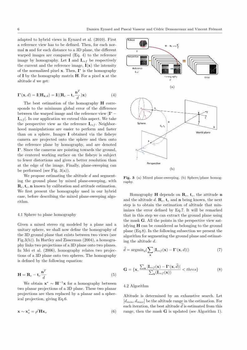
adapted to hybrid views in Eynard et al. (2010). First
a reference view has to be defined. Then, for each nor-
mal n and for each distance to a 3D plane, the different
warped images are compared (Eq. 4) to the reference
image by homography. Let I and Iref be respectively
the current and the reference image, I(x) the intensity
of the normalized pixel x. Then, I∗ is the homography
of I by the homography matrix H. For a pixel x at the
altitude d we get:
I∗(x, d) = I(Hx,d) = I((Rc − tcnT
d)x) (4)
The best estimation of the homography H corre-
sponds to the minimum global error of the difference
between the warped image and the reference view |I∗−Iref |. In our application we extend this aspect. We take
the perspective view as the reference Iref . Neighbor-
hood manipulations are easier to perform and faster
than on a sphere. Images I obtained via the fisheye
camera are projected onto the sphere and then onto
the reference plane by homography, and are denoted
I∗. Since the cameras are pointing towards the ground,
the centered working surface on the fisheye is subject
to fewer distortions and gives a better resolution than
at the edge of the image. Finally, plane-sweeping can
be performed (see Fig. 3(a)).
We propose estimating the altitude d and segment-
ing the ground plane by mixed plane-sweeping, with
Rc, tc,n known by calibration and attitude estimation.
We first present the homography used in our hybrid
case, before describing the mixed plane-sweeping algo-
rithm.
4.1 Sphere to plane homography
Given a mixed stereo rig modeled by a plane and a
unitary sphere, we shall now define the homography of
the 3D ground plane that exists between two views (see
Fig.3(b)). In Hartley and Zisserman (2004), a homogra-
phy links two projections of a 3D plane onto two planes.
In Mei et al. (2006), homography relates two projec-
tions of a 3D plane onto two spheres. The homography
is defined by the following equation:
H = Rc − tcnT
d(5)
We obtain x∗ ∼ H−1x for a homography between
two planar projections of a 3D plane. These two planar
projections are then replaced by a planar and a spher-
ical projection, giving Eq.6.
x ∼ x∗s = ρ′Hxs (6)
(a)
(b)
Fig. 3 (a) Mixed plane-sweeping. (b) Sphere/plane homog-raphy.
Homography H depends on Rc, tc, the attitude n
and the altitude d. Rc, tc and n being known, the next
step is to obtain the estimation of altitude that min-
imizes the error defined by Eq.7. It will be remarked
that in this step we can extract the ground plane using
the mask G. All the points in the perspective view sat-
isfying H can be considered as belonging to the ground
plane (Eq.8). In the following subsection we present the
algorithm for segmenting the ground plane and estimat-
ing the altitude d.
d = argmind(∑x
|Iref (x)− I∗(x, d)|) (7)
G = {x,∑
x |Iref (x)− I∗(x, d)|∑x(Iref (x))
< thres} (8)
4.2 Algorithm
Altitude is determined by an exhaustive search. Let
[dmin, dmax] be the altitude range in the estimation. For
each iteration, the best altitude d is estimated from this
range, then the mask G is updated (see Algorithm 1).

Real time UAV Altitude, Attitude and Motion Estimation from Hybrid Stereovision. 7
Pixels corresponding to the ground plane are in white
in figures 8(c) and 10(e). In order to obtain a real-time
method we estimate the altitude at time t using the
altitude at (t− 1).
Algorithm 1 Altitude and ground plane segmentation
algorithm - initialization
Estimation(dmin, dmax, s,∆d)
{Initialization}a0 = d−1 = dminb0 = d0 = dmaxG = {pεP ixels}while |dk − dk−1| > ∆d do{Estimation of the best altitude}dk+1 = argmin
d∈{ bk−aks−1
t+ak;tε[0,s−1]}∑
xεG |Iref (x)−
I∗(x, dk)|{Estimation of the mask of inliers/outliers}
G = {x,∑
x1εWx|Iref (x1)−I∗(x1,d)|∑x1εWx
Iref (x1)< thres}
{Estimation of the new range depending on sampling}ak+1 = dk+1 − bk−ak
s−1
bk+1 = dk+1 + bk−aks−1
k = k + 1end whileReturn d
The estimation is performed in two steps:
– Initialization: we estimate the best altitude from
within a wide altitude range.
– During flight we use the altitude estimated in the
initialization phase to obtain a narrower range in
Eq.10) with rd in Eq.9. This range depends on the
vertical velocity vv of UAV (about ±5m/s) and the
hardware’s computational power in frames per sec-
ond denoted fps.
rd =vvfps
103(mm) (9)
dtε[dt−1 − rd, dt−1 + rd] (10)
We now show how calibration, attitude, estimated
altitude and the ground plane segmentation, once ob-
tained, can be used to estimate autonomously the mo-
tion using the hybrid views, without any feature match-
ing between hybrid views.
5 Motion estimation
To estimate the motion we need the calibration (Rc, tc),
the altitude d at the meter scale, the attitude and the
ground plane segmentation G. The attitude can be de-
termined either by IMU or by vision using vanishing
points in urban environments, or the horizon line in nat-
ural environments. In the case of natural environments
the UAV’s heading has to be computed a posteriori, us-
ing such methods as Kalantari et al. (2009); Montiel and
A.-J. (2006); Scaramuzza and Siegwart (2008). Since
altitude, attitude, ground plane and calibration are de-
termined by vision or IMU, we decouple the rotation
and the translation of the motion. Below we present an
algorithm for estimating the translation from two sets
of points (Fig. 4(b)), that is to say points located on
the ground plane G and points located randomly in the
environment with depth either known or unknown. Our
algorithm is based on the technique of point tracking
in hybrid views for estimating the translation from two
views. The estimated translation t is then filtered and
smoothed by a Kalman filter.
5.1 Motion of the stereo rig
In each image, tracking is performed by the method
given in Bouguet (2000). We define xt a tracked point
in the image acquired at time t. Each point is related
by a rotation Rt relative to the world reference Xw
estimated by the IMU (see Eq.11).
xt = tRwXw ⇐⇒ Xw = tR−1w xt (11)
Then, for a couple of points in the image (xt; xt+1)
that indicate motion between times t and t+ 1, we can
express the point xt from the frame t to the frame t+1
by Eq.12. We thus obtain a rotation corresponding to
motion (eq.13).
xt+1 = t+1RwtR−1w xt (12)
Rt+1 = t+1RwtR−1w (13)
The points are related by a motion composed of
the rotation Rt+1 previously defined and the transla-
tion tt+1 (Fig.4(a), Eq.14). The distance of the image
point to the 3D point is defined by the altitude d (see
Fig.4(a)) known by plane-sweeping in the case of a point
belonging to the ground plane.
xt+1 = d Rt+1xt + tt+1 (14)

8 Damien Eynard and Pascal Vasseur and Cedric Demonceaux and Vincent Fremont
(a)
(b)
Fig. 4 fig. 4(a) 3D points located on the ground plane and inthe environment. Fig. 4(b) Combining points located in theenvironment and the ground plane from hybrid views.
5.2 Motion from ground points
As mentioned previously, plane-sweeping is used to es-
timate both the altitude and the segmentation of the
ground plane G. Knowledge of these parameters entails
knowledge of tracked points in the two views belong-
ing to the ground plane, together with their depth (see
Fig.4(a)). Then, the motion is estimated at the metric
scale and defined as follows, with × the cross product
of two vectors:
(xt+1 × tt+1) = −d(xt+1 ×Rt+1xt) (15)
We now show how motion can be estimated in each
view and then in the mixed view. First, in the spherical
an referential case, we obtain the matrices As Eq.16
and Bs Eq.17. Secondly, in the perspective case, images
are considered to be rectified by the rotation Rc, and
we obtain the matrices Ap Eq.16 and Bp Eq.18. In the
hybrid case As and Ap are concatenated in Ah, and
Bs and Bp are concatenated in Bh. Finally, we obtain
Eq.22.
As/p =
0 −xt+1 xt+1
zt+1 0 −xt+1
−yt+1 xt+1 0
(16)
Bs = −ds (xt+1 ×Rt+1xt)T (17)
Bp = −dp ((xt+1×Rt+1xt) + xt+1× ((Rt+1− Id)tc))T
(18)
5.3 Motion from environment points
Concerning points located randomly in the environ-
ment, without possessing any knowledge of their depth
we can extend to the mixed view the motion estimation
proposed by Bazin et al. (2010) for the spherical view
(see Fig.4(a)). The translation tt+1 from two points is
defined as in Eq.19 . As mentioned previously, perspec-
tive points and spherical points are concatenated in or-
der to estimate the translation tt+1 for obtaining the
relation in Eq.23.
(Rt+1xt × xt+1)T · tt+1 = 0 (19)
5.4 Combining 3D points from mixed views
Note: In this part, we adapt the generic formulation to
the case of perspective case. xpi,t denotes the ith point
tracked in the perspective view at time t, and xsi,t de-
notes the ith point tracked in the sphere at the time t.
Ch =
Rt+1xs0,t × xs0,t+1
...
Rt+1xsm,t × xsm,t+1
Rt+1xp0,t × xp0,t+1
...
Rt+1xpn,t × xpn,t+1
(20)

Real time UAV Altitude, Attitude and Motion Estimation from Hybrid Stereovision. 9
Considering perspective images rectified by Rc known
by calibration, we get:
Dh =
0...
0
(Rt+1xp0,t × xp0,t+1).(Rt+1tc − tc)...
(Rt+1xpn,t × xpn,t+1).(Rt+1tc − tc)
(21)
Ahtt+1 = Bh (22)
Chtt+1 = Dh (23)
We have already presented a generic formulation
for translation estimation, either from ground points or
from environment points. When translating from pla-
nar points, the translation is estimated at the metric
scale. However, the main drawback in the case of 3D
motion is the pixel projection noise sensitivity. When
translating from environment points, on the other hand,
motion estimation has the advantage of being more ro-
bust to noise than on the plane, but the estimation is
performed up to scale. One of the contributions of this
paper is thus the combination of the two methods to in-
crease both accuracy and robustness. The first method
is defined by Eq. 22, and the second by Eq. 23. Ch is
defined by Eq. 21. Concatenating the matrices Ah and
Ch yields Afus, and concatenating Bh and Dh gives us
Bfus. Finally we obtain the Afustt+1 = Bfus solved by
least squares.
Figure 5 illustrates the advantages of combining 3D
points and ground points. The introduced error is a ran-
dom angle, applied to view-lines whichever the projec-
tion model used. The angle error is computed between
the real vector of translation and the estimated vector
of translation.
5.5 Kalman filtering
Once the motion has been estimated at the metric scale
we observe certain discontinuities and brutal variations.
In order to reduce bad estimations and to refine the
trajectory, we have chosen to use a linear Kalman fil-
ter Kalman (1960). The considered state is simply the
translation vector of the ego-motion i.e. Xk = tt+1, and
is modeled as a linear Gaussian system given by Eq. 24:
Xk+1 = EXk + VkYk = OXk +Wk
(24)
Fig. 5 Comparison of Ground Points, 3D Points and 3D +Ground Points. Dashed lines represent estimation from 3D offused points while plain lines represent estimation from planarpoints. A smaller slope corresponds to a low sensitivity of thecorresponding algorithm to the noise.
where E = Id3 is the linear state transition model
and O = Id3 the observation model, assuming con-
stant speed during a sample interval. The vectors Vkand Wk correspond respectively to the error model and
the observation noise. They are assumed to be addi-
tive and white zero-mean Gaussian, with user-defined
covariance matrices. In order to retain the dynamic na-
ture of the measurement, more uncertainty is given to
the measures, i.e. 106 and 102 for the model. Given the
above considerations, the Kalman filter consists in pre-
dicting the translation vector tt+1 and then obtaining
a refined value using an update step when a new obser-vation is available. We therefore obtain the translation
vector of the ego-motion and its estimated accuracy,
from all past observations up to the current time.
6 Results
In this section we present the results of the different
methods. First, a ground truth comparison is used to
validate the effectiveness of each method and also its
accuracy, then each method is tested on UAV image
sequences. Finally, we analyze the performance of the
algorithm.
6.1 Attitude
First, attitude can be provided either by vision or by
IMU. For the case of vision, two types of methods are

10 Damien Eynard and Pascal Vasseur and Cedric Demonceaux and Vincent Fremont
analyzed: in urban environments and natural environ-
ments. Results are compared to an IMU.
Attitude estimation by vanishing points
(a)
(b)
Fig. 6 (a) Comparison between attitude estimated by IMU(red) and by vision (blue). (b) Influence of attitude error(pitch and roll) on the estimation of altitude.
We employ the method of Demonceaux et al. (2007)
and Bazin et al. (2008). The error introduced by this
method does not exceed 3◦. Our algorithm is insensitive
to low attitude errors. For example, with real images,
an error of 5◦ for the roll and the pitch will introduce
respectively an error of 0.87% and 0.39% (fig. 6(b))
for altitude estimation. This method, which has been
tested on our fisheye lens, is as good as a catadioptric
lens at estimating attitude. In the works presented here,
attitude can be estimated in real time (around 30 Hz).
Indoor experiments were carried out using a Pel-
ican UAV, where vanishing points can be determined.
Fig.6(a) and Table 1 present the results the from vision-
based method (blue line) and IMU (red line). Notice
that the red curve is smoothed by the IMU Kalman fil-
ter. Finally, for the yaw, the absolute offset between
the vision estimation and the IMU is removed by :
yi,vp = yi,vp − yvp + yimu, with yi,vp the ith value esti-
mated by vanishing points, yimu the mean of yaw angles
estimated by IMU.
Type Roll Pitch YawError max 3.97◦ 2.43◦ 5◦
Mean of absolute error 1.32◦ 1.96◦ 0◦
Std of error 1.65◦ 2.07◦ 0.78◦
Table 1 Attitude Comparison for IMU vs. the VisionMethod
Attitude estimation from the horizon line
We compared the attitude provided by horizon line
detection to IMU. For the image in Fig.7(a) we ob-
tain an error of less than 1◦. Fig.7(b) represents the
ground/sky segmentation after detection of the horizon
line. The C++ real-time algorithm provides an aver-
age of 80 Hz after the first initialization, on offboard
processor.
(a) (b)
Fig. 7 (a) View from the UAV’s fisheye. (b) Segmentedground/sky.
6.2 Altitude
Once the calibration and attitude have been estimated
we proceed to estimate the altitude. We compare our
algorithm to a laser telemeter, and UAV altitude esti-
mation validates the effectiveness of this approach.
6.2.1 Comparison with the ground truth
We present two cases of experimental results where real
altitude is estimated by a laser telemeter. The error ε
between actual and estimated altitude is expressed as
ε =(d−dgt)dgt
, with dgt the ground truth of the altitude.
– Case 1: two cameras with a 447mm baseline are
fixed on a pneumatic telescopic mast. Altitude and
ground plane estimation are performed offline on a
GPU.

Real time UAV Altitude, Attitude and Motion Estimation from Hybrid Stereovision. 11
– Case 2: two micro cameras with a 314mm baseline
are embedded on a compact UAV. Altitude estima-
tion is performed online by CPU processing.
In the first experiment we observe an accurate es-
timation of altitude on a free ground plane (tab. 2),
with an error between 0.18% and 3.14%. When there
are obstacles on the ground plane, we observe a higher
error, between 7.52% and 8.82%. The higher the alti-
tude, the less accurate the estimation because of the
decrease in resolution as altitude increases. Moreover,
the accuracy depends on the size of the baseline. This
fact does not impact our application negatively, given
that accuracy is most critical during the two phases of
landing and take-off, i.e. where the UAV is close to the
ground plane.
Type Grnd truth Estim. altitude ErrorFree Ground 2187mm 2200mm 0.59%Free Ground 3244mm 3250mm 0.18%
Gnd + obstacles(low contrast) 3244mm 3488mm 7.52%Free Ground 4072mm 4200mm 3.14%Free Ground 5076mm 5202mm 2.48%
Gnd + obstacles 4080mm 4440mm 8.82%
Table 2 Altitude ground plane estimation with and withoutobstacles - Algorithm parameters for this test: s = 6, thres =25
The second aspect of our algorithm is the segmen-
tation of the ground plane, which is well estimated for
contrasted areas. In case of a plane without obstacles,
the pneumatic telescopic mast, where cameras are fixed,
is well represented by outliers (dark on the image) (Fig.
8(c)). For an image composed of a dominant ground
plane and walls, the ground plane is segmented as in-
liers, while walls are segmented as outliers. Our algo-
rithm allows inliers/outliers to be segmented globally
when estimating the dominant ground plane for our
application.
The aspect of our algorithm in greatest need of im-
provement is where there are poorly textured planes
and reflections which depend on camera orientation.
When the ground plane or outliers (walls, objects) are
homogeneous or poorly textured, the segmentation of
outliers/inliers becomes difficult.
6.2.2 UAV Altitude Estimation
For the second experiment we implemented our system
on a small quadrotor UAV. Micro cameras embedded
on the UAV are linked to an external laptop to perform
online altitude estimation. We tested the accuracy by
Fig. 9 Altitudes (cross) are estimated by plane-sweeping andthe line represents measurements from the laser range finderbased on himself, thus ideal measures.
comparing altitudes estimated by plane-sweeping to al-
titudes estimated by laser telemeter. Fig.9 shows that
altitude is well estimated for the range of altitudes cor-
responding to the landing and take-off phases of a UAV.
The mean error is 2.41%.
6.2.3 UAV Ground Plane Segmentation
By estimating the altitude from the two views (Fig.
10(a),10(b) and the homography (Fig. 10(c)), the ground
plane (Fig. 10(e)) is segmented using the error (Fig.
10(d)) and becomes the mask G. Figure 10(e) shows
the good segmentation of planar (white pattern) and
non-planar objects (cables in black) after the thresh-
old.
6.2.4 Performances
First we developed the algorithm on GPU with brook+
for ATI that gives a real-time (30 Hz) frame rate in
order to estimate altitude and to segment the ground
plane. The algorithm was tested on ATI 4850 with an
E8400 3Ghz CPU.
We then implemented the algorithm on a CPU with
a good deal of optimizing and without segmenting the
ground plane. With this implementation we obtained
min : 80 Hz,mean : 180 Hz,max : 250 Hz, that is to say
values higher than the video frame rate, which meant
that we could use our algorithm for online processing.
The platform for our tests is a Macbook Pro with a C2D
P8400 2.26Ghz CPU. A demonstration can be seen at
Eynard (2010). We use a stereo rig with uEye cameras
and get the normal of the ground plane with an IMU.
During this demonstration, the system is able to esti-
mate altitude in real time with robustness and accuracy.
An embedded version of our algorithm was exported
to the ARM of a Gumstix Overo Fire with OMAP3530
ARM @600Mhz based processor. With this implemen-
tation we get a frame rate of around 5 Hz, which is not

12 Damien Eynard and Pascal Vasseur and Cedric Demonceaux and Vincent Fremont
(a) (b) (c) (d) (e)
Fig. 8 Altitude and ground plane segmentation - 4.8% of inliers - Fisheye view (a), perspective view (b), ground planesegmentation (c), sphere to plane homography (d), reference and homography comparison (e)
(a) (b) (c) (d) (e) (f)
Fig. 10 (a) embedded view of the Pelican UAV (from left to right: fisheye and perspective views) - Est. altitude 1912mm.(b) Homography of fisheye view to the reference (c) Error (d) Ground plane segmentation G (e) Altitude of the trajectoryestimated by plane-sweeping.
enough for real-time applications, but relatively inter-
esting given the power/size ratio.
By developing these algorithms on GPU, CPU and
an embedded board we obtained interesting results. For
simultaneous ground plane segmentation and altitude
estimation, results are real time and can be implemented
on a UAV with GPU. For altitude estimation only, com-
putation is faster and can be implemented on smaller
quadrotor UAV.
6.3 Motion
We propose estimating motion using a linear method,
namely least squares (LS). This method is robust to
Gaussian noise, but sensitive to outliers Malis and Marc-
hand (2005). For this reason, outliers are rejected by the
RANSAC method Hartley and Zisserman (2004). This
method was first validated on robot arm performing a
loop, as we now describe.
6.3.1 Comparison with the ground truth
The system is presented in Fig.11(b), and images are
processed offline. In each view the number of tracked
points is between 50 and 200. In 11(c), we compare our
algorithm with the ground truth, up to the micrometer,
obtained by the robot arm. The trajectory is a square
of side 330 mm, with a total motion of 1320 mm. All
trajectories are expressed within the same coordinate
system of the robot arm. First we estimate the altitude
by plane-sweeping (Fig. 10(f)). Then the motion is es-
timated using the derotation obtained from IMU (blue
line) or from the ground truth (green line). In the blue
case, the error is 19.084 mm in XYZ, or 1.45%. In the
green case, the error is 15.865 mm in XYZ, or 1.20%.
6.3.2 UAV motion estimation
Once it had been validated, we tested our algorithm
on a quadrotor with two uEye cameras with images
processed offline. This validation was performed both
indoors and outdoors. A Xsens IMU provides the at-
titude and the rotation of the motion while altitude is
estimated via plane-sweeping. In each view, the number
of tracked points is between 50 and 200. We assume that
the perspective camera is pointing at the ground and
looking at planar points, while the fisheye observes en-
vironment points. In an indoor environment, Fig.12(a)
presents the final 3D trajectory of the motion estima-
tion. Raw data sensitive to noise and bad estimations
are shown in red, while data filtered and smoothed by
Kalman filter are shown in blue. In other experiment,
Fig.13(a) presents the final trajectory in green, super-
imposed to an external view.
In the outdoor environment the ground texture, mainly
grass, means that the plane-sweeping algorithm can-
not give accurate results, because of ambiguities in the
search range. The poorly textured ground, the high al-
titude (15 m), and the short baseline make altitude es-
timation difficult. In this case we hand altitude esti-
mation over to a pressure altimeter, embedded on the
UAV. Fig.14(a) shows the motion estimated by GPS fil-
tered by the altitude provided by the pressure altimeter.
We then estimate the motion using embedded IMU to
estimate the attitude and the rotation of the motion.

Real time UAV Altitude, Attitude and Motion Estimation from Hybrid Stereovision. 13
(a)
(b)
(c)
Fig. 11 Loop of a robot 11(c) with hybrid and merged views,Fig.11(a) fisheye and perspective views of the mobile robot.
6.3.3 Performances
The algorithm was implemented in C++ and tested
on a Macbook Pro. Estimating rotation by IMU and
with tracking points on two images of 752 × 480, we
could estimate the translation up to 24 Hz. The Lucas
Kanade tracker has been adapted Sanahuja (2010) for
the OMAP 3530 DSP, that allows real-time tracking for
one image per Gumstix.
(a)
Fig. 12 3D trajectory of the UAV.
(a)
Fig. 13 Motion in indoor environment with Pelican.
7 Conclusions and future works
This paper presents a hybrid stereo system composed
of fisheye and perspective views, modeled respectively
by a sphere and a plane, which is able to estimate nav-
igation parameters for a UAV without the use of any
other sensor. Navigation parameters are attitude, alti-
tude, ground plane segmentation and motion, assuming
calibrated cameras.
Projecting the horizon line can determine the atti-
tude, as well as vanishing points obtained from lines in
an urban environment. The projections of the ground
plane onto the sphere and the plane are related by a ho-
mography which allows both altitude and ground plane
to estimated using plane-sweeping. Once the altitude
has been estimated and the ground plane segmented,
tracked points on the ground provide the information
for metric translation, while environment points give an

14 Damien Eynard and Pascal Vasseur and Cedric Demonceaux and Vincent Fremont
(a)
Fig. 14 Taking-off in natural environment with MD4-1000.The red line represents GPS ground truth. The purple lineis the estimated motion and green line the estimated motionfiltered by Kalman filter (for more details, please refer tocorresponding video).
accurate estimation of translation up to scale. By com-
bining points from mixed views, and by merging two
sets of points, translation is estimated accurately using
the metric information, and smoothed by Kalman filter.
The methods we propose are real-time methods that
do not require matching between hybrid views. We show
in this article that our sensor is able to solve the main
drawbacks of conventional sensors by using a compact,
low power-consumption, passive, accurate, robust vi-
sion sensor. Furthermore, once navigation parameters
have been estimated, this system is available to perform
other visual tasks such as surveillance and environment
discovery.
Perspectives of this work will be the development of
a new hardware architecture able to grab stereo images
and provide all the parameters in parallel, as well as
integrating the estimated parameters into the control
loop.
8 Acknowledgments
This work is supported by the European FEDER (Fonds
Europeen de Developpement Regional) and Region Pi-
cardie Project ALTO (Automatic Landing and Take-
Off).
References
M. Achtelik, A. Bachrach, R. He, S. Prentice, and
N. Roy. Stereo vision and laser odometry for au-
tonomous helicopters in gps-denied indoor environ-
ments. In SPIE, 2009.
J. Artieda, J. M. Sebastian, P. Campoy, J. F. Correa,
I. F. Mondragon, C. Martınez, and M. Olivares. Vi-
sual 3-d slam from uavs. Journal of Intelligent and
Robotic Systems, 55(4-5):299–321, 2009.
S. Baker and S. K. Nayar. A theory of single-viewpoint
catadioptric image formation. International Jour-
nal of Computer Vision, 35:175–196, 1999. ISSN
0920-5691. URL http://dx.doi.org/10.1023/A:
1008128724364. 10.1023/A:1008128724364.
J. Barreto and A. H. Issues on the geometry of central
catadioptric image formation. International Confer-
ence On Pattern Recognition, 2001.
G. Barrows, C. Neely, and K. Miller. Optic flow sensors
for mav navigation. 195:557–574, 2001.
Y. Bastanlar, A. Temizel, Y. Yardimci, and P. F. Sturm.
Effective structure-from-motion for hybrid camera
systems. In ICPR’10, pages 1654–1657, 2010.
J. Bazin, I. Kweon, C. Demonceaux, and P. Vasseur.
Uav attitude estimation by vanishing points in cata-
dioptric image. In IEEE International Conference
on Robotics and Automation 2008 (ICRA’08), pages
2743–2749, Pasadena, CA, May 2008. IEEE.
J. Bazin, C. Demonceaux, P. Vasseur, and I. Kweon.
Motion estimation by decoupling rotation and trans-
lation in catadioptric vision. Computer Vision and
Image Understanding, Volume 114, Issue 2(0):254–
273, February 2010.
A. Beyeler, C. Mattiussi, J. christophe Zufferey, and
D. Floreano. Visionbased altitude and pitch estima-
tion for ultra-light indoor aircraft. In in IEEE In-
ternational Conference on Robotics and Automation
ICRA’06, pages 2836–2841, 2006.
M. Blosch, S. Weiss, D. Scaramuzza, and R. Siegwart.
Vision based mav navigation in unknown and un-
structured environments. IEEE International Con-
ference on Robotics and Automation (ICRA 2010),
2010.
J.-Y. Bouguet. Pyramidal implementation of the lu-
cas kanade feature tracker description of the algo-
rithm, 2000. URL http://robots.stanford.edu/
cs223b04/algo_tracking.pdf.
G. Caron and D. Eynard. Multiple camera types si-
multaneous stereo calibration. In IEEE Int. Conf.
on Robotics and Automation, ICRA’11, Shanghai,
China, May 2011.
J. S. Chahl, M. V. Srinivasan, and S.-W. Zhang. Land-
ing strategies in honeybees and applications to unin-
habited airborne vehicles. I. J. Robotic Res., 23(2):
101–110, 2004.
A. Cheriany, J. Andersh, V. Morellas, N. Pa-
panikolopoulos, and B. Mettler. Autonomous al-

Real time UAV Altitude, Attitude and Motion Estimation from Hybrid Stereovision. 15
titude estimation of a uav using a single onboard
camera. In Proceedings of the 2009 IEEE/RSJ in-
ternational conference on Intelligent robots and sys-
tems, IROS’09, pages 3900–3905, Piscataway, NJ,
USA, 2009. IEEE Press. ISBN 978-1-4244-3803-
7. URL http://portal.acm.org/citation.cfm?
id=1732643.1732689.
R. Collins. A space-sweep approach to true multi-image
matching. In IEEE Computer Vision and Pattern
Recognition, pages 358–363, June 1996.
A. J. Davison, I. D. Reid, N. Molton, and O. Stasse.
Monoslam: Real-time single camera slam. IEEE
Trans. Pattern Anal. Mach. Intell., 29(6):1052–1067,
2007.
C. Demonceaux, P. Vasseur, and C. Pegard. Ro-
bust attitude estimation with catadioptric vision. In
IEEE/RSJ International Conference on Intelligent
Robots and Systems 2006 (IROS’06), pages 3448–
3453, Beijing, China, October 2006. IEEE.
C. Demonceaux, P. Vasseur, and C. Pegard. Uav at-
titude computation by omnidirectional vision in ur-
ban environment. In IEEE International Conference
on Robotics and Automation 2007 (ICRA’07), pages
2017–2022, Roma, Italy, April 2007. IEEE.
C. Demonceaux, P. Vasseur, and Y. D. Fougerolle. Cen-
tral catadioptric image processing with geodesic met-
ric. Image Vision Comput., 29(12):840–849, 2011.
D. Dusha, W. W. Boles, and R. Walker. Fixed-
wing attitude estimation using computer vision based
horizon detection. In 12th Australian International
Aerospace Congress, pages 1–19, Melbourne Aus-
tralia, 2007. URL http://eprints.qut.edu.au/
6852/.
D. Eberli, D. Scaramuzza, S. Weiss, and R. Siegwart.
Vision based position control for mavs using one sin-
gle circular landmark. Journal of Intelligent and
Robotic Systems, 61(1-4):495–512, 2011.
D. Eynard, 2010. URL http://www.youtube.com/
watch?v=ubXzf0eLud4.
D. Eynard, P. Vasseur, C. Demonceaux, and V. Fre-
mont. Uav altitude estimation by mixed stereoscopic
vision. In IEEE Int. Conf. on Intelligent RObots and
Systems, IROS’10, Taipei, Taiwan, October 2010.
D. Eynard, P. Vasseur, C. Demonceaux, and V. Fre-
mont. Uav motion estimation using hybrid stereo-
scopic vision. In IAPR Conf. on Machine Vision
Applications, MVA’11, Nara, Japan, June 2011.
F. Fraundorfer, D. Scaramuzza, and M. Pollefeys.
A constricted bundle adjustment parameterization
for relative scale estimation in visual odometry,
2010. URL http://ieeexplore.ieee.org/xpls/
abs_all.jsp?arnumber=5509733.
D. Gallup, J.-M. Frahm, P. Mordohai, Q. Yang, and
M. Pollefeys. Real-time plane-sweeping stereo with
multiple sweeping directions, 2007.
P. J. Garcia-pardo, G. S. Sukhatme, and J. F. Mont-
gomery. Towards vision-based safe landing for an
autonomous helicopter. 2000.
W. E. Green, P. Y. Oh, K. Sevcik, and G. Barrows.
Autonomous landing for indoor flying robots using
optic flow. In in ASME International Mechanical En-
gineering Congress and Exposition, pages 1347–1352,
2003.
R. Hartley and A. Zisserman. Multiple View Geometry
in Computer Vision. Cambridge University Press,
ISBN: 0521540518, second edition, 2004.
Hyscas. Hybrid stereoscopic calibration software. In
http://www.hyscas.com, 2011.
M. Kalantari, A. Hashemi, F. Jung, and J.-P. Guedon.
A new solution to the relative orientation problem
using only 3 points and the vertical direction. CoRR,
abs/0905.3964, 2009.
M. Kalantari, A. Hashemi, F. Jung, and J.-P. Guedon.
A new solution to the relative orientation problem
using only 3 points and the vertical direction. Journal
of Mathematical Imaging and Vision, 39(3):259–268,
2011.
R. E. Kalman. A new approach to linear fil-
tering and prediction problems. 1960. URL
http://www.cs.unc.edu/~welch/kalman/media/
pdf/Kalman1960.pdf.
G. H. Lee, M. Achtelik, F. Fraundorfer, M. Pollefeys,
and R. Siegwart. A benchmarking tool for mav vi-
sual pose estimation. In ICARCV, pages 1541–1546.
IEEE, 2010.
G. H. Lee, F. Fraundorfer, and M. Pollefeys. Mav visual
slam with plane constraint. In ICRA, pages 3139–
3144, 2011.
J. Lee, S. You, and U. Neumann. Large motion
estimation for omnidirectional vision. Omni-
directional Vision, Workshop on, 0:161, 2000.
doi: http://doi.ieeecomputersociety.org/10.1109/
OMNVIS.2000.853824.
M. Lhuillier. Automatic scene structure and camera
motion using a catadioptric system. Computer Vision
and Image Understanding, 109:186–203, 2008. doi:
10.1016/j.cviu.2007.05.004.
H. Li, R. I. Hartley, and J.-H. Kim. A linear approach to
motion estimation using generalized camera models.
In CVPR’08, pages –1–1, 2008.
M. Lourenco, J. P. Barreto, and A. Malti. Feature de-
tection and matching in images with radial distor-
tion. In ICRA, pages 1028–1034, 2010.
E. Malis and E. Marchand. Methodes robustes
d’estimation pour la vision robotique. In Journees

16 Damien Eynard and Pascal Vasseur and Cedric Demonceaux and Vincent Fremont
nationales de la recherche en robotique, JNRR’05,
Guidel, France France, 2005. URL http://hal.
inria.fr/inria-00351893/en/.
E. Marchand and F. Chaumette. Virtual visual ser-
voing: A framework for real-time augmented real-
ity. In EUROGRAPHICS 2002 Conference Pro-
ceeding, volume 21(3), pages 289–298, Saarebrun,
Germany Germany. URL http://hal.inria.fr/
inria-00352096/en/.
C. Mei and P. Rives. Single view point omnidirectional
camera calibration from planar grids. In IEEE In-
ternational Conference on Robotics and Automation,
April 2007.
C. Mei, S. Benhimane, E. Malis, and P. Rives.
Homography-based tracking for central catadioptric
cameras. In IN IROS, 2006.
D. Mellinger, N. Michael, M. Shomin, and V. Kumar.
Recent advances in quadrotor capabilities. In ICRA,
pages 2964–2965, 2011.
J. M. M. Montiel and D. A.-J. A visual com-
pass based on slam. In In Proc. Intl. Conf. on
Robotics and Automation, 2006(accepted. Available:
http://pubs.doc.ic.ac.uk/visual-compass-slam, 2006.
O. Naroditsky, X.-S. Zhou, J. Gallier, S.-I. Roumeliotis,
and K. Daniilidis. Two efficient solutions for visual
odometry using directional correspondence. IEEE
Transactions Pattern Analysis and Machine Intel-
ligence, 2011. URL http://www.cis.upenn.edu/
~kostas/mypub.dir/oleg2011pami-revised.pdf.
Under review.
D. Nister. An efficient solution to the five-point rela-
tive pose problem. IEEE Trans. Pattern Anal. Mach.
Intell., 26(6):756–777, 2004.
G. Nutzi, S. Weiss, D. Scaramuzza, and R. Siegwart.
Fusion of imu and vision for absolute scale estimation
in monocular slam. Journal of Intelligent and Robotic
Systems, 61(1-4):287–299, 2011.
O. Oreifej, N. da Vitoria Lobo, and M. Shah. Horizon
constraint for unambiguous uav navigation in planar
scenes. In ICRA, pages 1159–1165, 2011.
R. Pless. Using many cameras as one. In In CVPR,
pages 587–593, 2003.
L. Puig, J. Guerrero, and P. Sturm. Matching of
omindirectional and perspective images using the
hybrid fundamental matrix. In Proceedings of the
Workshop on Omnidirectional Vision, Camera Net-
works and Non-Classical Cameras, Marseille, France,
oct 2008. URL http://perception.inrialpes.fr/
Publications/2008/PGS08.
G. Sanahuja. Commande et localisation em-
barquee d’un drone aerien en utilisant la vi-
sion, January 2010. URL http://www.hds.
utc.fr/~gsanahuj/dokuwiki/lib/exe/fetch.
php?id=frAccueil&cache=cache&media=fr:
these_guillaume_sanahuja.pdf.
S. Saripalli, J. F. Montgomery, and G. S. Sukhatme.
Vision-based autonomous landing of an unmanned
aerial vehicle. In IEEE International Conference on
Robotics and Automation (ICRA, pages 2799–2804,
2002.
D. Scaramuzza. 1-point-ransac structure from mo-
tion for vehicle-mounted cameras by exploiting
non-holonomic constraints. International Journal
of Computer Vision, pages 1–12, 2011. ISSN
0920-5691. URL http://dx.doi.org/10.1007/
s11263-011-0441-3. 10.1007/s11263-011-0441-3.
D. Scaramuzza and R. Siegwart. Correcting vehicle
heading in visual odometry by using image appear-
ance. In Proc. of The First International Workshop
on Omnidirectional Robot Vision, November 2008.
C. S. Sharp, O. Shakernia, and S. S. Sastry. A vi-
sion system for landing an unmanned aerial vehicle.
In IEEE International Conference on Robotics and
Automation (ICRA), Seoul, Korea, pages 1720–1727,
2001.
S. Thurrowgood, D. Soccol, R. J. D. Moore, D. P.
Bland, and M. V. Srinivasan. A vision based sys-
tem for attitude estimation of uavs. In IROS, pages
5725–5730. IEEE, 2009.
S. Weiss, D. Scaramuzza, and R. Siegwart. Monocular-
slam-based navigation for autonomous micro he-
licopters in gps-denied environments. J. Field
Robotics, 28(6):854–874, 2011.
X. Ying and Z. Hu. Can we consider central
catadioptric cameras and fisheye cameras within
a unified imaging model. In T. Pajdla and
J. Matas, editors, Computer Vision - ECCV 2004,
volume 3021 of Lecture Notes in Computer Sci-
ence, pages 442–455. Springer Berlin / Heidel-
berg, 2004. URL http://dx.doi.org/10.1007/
978-3-540-24670-1_34. 10.1007/978-3-540-24670-
1 34.