realtime dsp: the tms320c30 course - ptolemy projectjohnr/papers/pdf/c30course.pdf · the digital...
TRANSCRIPT

Realtime DSP:
The TMS320C30 Course
Revision 3
20 February 1994
John ReekieSchool of Electrical Engineering
University of Technology, SydneyPO Box 123
Broadway NSW 2007Australia
email: [email protected]

ii
© John Reekie 1992, 1993, 1994. This document was produced for non-profiteducational purposes. It may be freely copied and distributed in electronic orpaper form for personal and non-fee-paying educational use, provided that it iscopied and distributed intact with the title page and this notice included. For allother uses and forms of distribution, including but not limited to fee-payingcourses, inclusion with commercial software or literature of any kind, or any otheruse not specifically mentioned above, explicit written permission and/or alicensing agreement must be obtained from the author.
Reception of comments and suggestions on this document is assumed to constitutepermission to incorporate them into future revisions together with an appropriateacknowledgement.

iii

iv
ContentsIntroduction................................................................................................................... 1
Assumed knowledge.............................................................................................. 1Hardware and software requirements................................................................... 1The DSPKit library, and other materials ............................................................... 2Terms of use........................................................................................................... 2
The Development Tools ............................................................................................... 3Overview ................................................................................................................ 3The compiler shell ................................................................................................. 3The assembler ........................................................................................................ 5The linker ............................................................................................................... 6
Basic Instructions .......................................................................................................... 9Architecture overview ............................................................................................ 9Addressing modes................................................................................................ 10Basic data instructions ......................................................................................... 12Basic control flow instructions ............................................................................ 17
Conditional Instructions ............................................................................................. 19Condition flags, codes, and instructions ............................................................. 19Conditional instruction examples ....................................................................... 22
More On Addressing................................................................................................... 27Indirect addressing ............................................................................................... 27The memory map................................................................................................. 30Direct addressing ................................................................................................. 31
C-Assembler Interfacing ............................................................................................. 33The stack .............................................................................................................. 33The C calling interface......................................................................................... 35Register usage ...................................................................................................... 39A minimal calling interface.................................................................................. 39
Advanced Instructions ................................................................................................ 41Delayed branches................................................................................................. 41Repeat instructions ............................................................................................... 43Parallel Instructions.............................................................................................. 44
Special Addressing Modes .......................................................................................... 51Circular addressing............................................................................................... 51Bit-reversed addressing........................................................................................ 53Allocating memory arrays.................................................................................... 55
On-chip Peripherals .................................................................................................... 57Overview of peripherals ...................................................................................... 57The timers ............................................................................................................ 57Accessing hardware memory locations in C....................................................... 58
Interrupts ..................................................................................................................... 63C30 interrupt structure ......................................................................................... 63Interrupts and polling .......................................................................................... 64Accessing and controlling interrupts in C .......................................................... 66
Memory Management ................................................................................................. 69
Pipeline Conflicts ........................................................................................................ 70

1
Introduction
This is a course on programming a special type of micro-processor—the DSP, orDigital Signal Processor. This particular course is based on the Texas InstrumentsTMS320C30 device, which is representative of the Texas Instruments’ floating-pointDSP family. Other members include the TMS320C31 and TMS320C40. There areseveral other floating-point DSPs readily available, including the MotorolaDSP96002 and the Analog Devices ADSP-21020.
The focus of the course is on DSP programming. It does not teach digital signalprocessing theory, nor does it teach computer programming, since it assumessome knowledge of both. I have attempted to make the course useful to peoplewho have a need to know—in other words, for people who need material thatexplains concisely what they need to know to complete a particular task. I havealso tried to structure these notes so that they can continue to be used as referencematerial.
I expect that the course could be useful as:
— A professional development course for practicing engineers
— An introductory course for thesis and research students working in DSP
They can also form the basis of an introductory undergraduate subject, althoughadditional exercises and tutoring will be needed.
There are some rough edges and unfinished sections in this document. I hope toproduce another release that corrects these deficiencies in late 1994.
Assumed knowledgeThe course assumes that your have at least some familiarity with the Cprogramming language and some experience with microprocessors and assemblercoding (although not TMS320C30 assembler). You do not need any knowledge ofthe digital signal processing theory to do this course (and the course won’t teachyou any), although you will definitely need some knowledge about the applicationarea for which to intend to write real-time DSP programs. It is well beyond thescope of this particular course to give you that knowledge.
Incidentally, the breadth of applications in which DSPs can be used is surprisinglylarge, and growing: modems and faxes, data encryption, data transmission, speechcompression, speech recognition and synthesis, image compression andenhancement, robot vision, digital audio, music synthesis, vehicle navigation,seismic and spectral analysis, radar and sonar, servo and motor control, ECGmonitoring, auditory aids, prosthetics.
Hardware and software requirementsTo make effective use of this course, you will of course need access to TexasInstruments’ development tools. The development system we use in our laboratoryat the University Technology, Sydney, is the Texas Instruments EVM (EvaluationModule). This is a relatively cheap development system with a single channel ofon-board A/D/A conversion. However, there are many other suitable platforms, aswell as a TMS320C30 simulator.
The software tools you will need access to are:
Realtime DSP: The TMS320C30 Course
2
• Floating-point DSP C Compiler, version 4.5 or later. (You can probably stillmake use of these notes if you do not have the C compiler.)
• Floating-point DSP Assembler and Linker, version 4.5 or later.
• TMS320C30 Source Debugger
You will need access to the following manuals:
• TMS320C3X User's Guide, literature number SPRU031B.
• TMS320 Floating-Point DSP Optimizing C Compiler User's Guide, literaturenumber SPRU034E.
• TMS320 Floating-Point DSP Assembly Language Tools User's Guide, literaturenumber SPRU035A.
• TMS320C3X C Source Debugger, literature number SPRU053A.
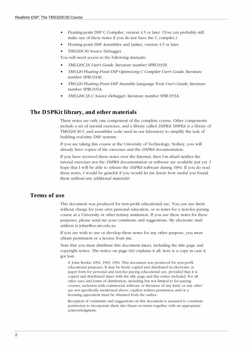
The DSPKit library, and other materialsThese notes are only one component of the complete course. Other componentsinclude a set of tutorial exercises, and a library called DSPKit. DSPKit is a library ofTMS320C30 C and assembler code used in our laboratory to simplify the task ofbuilding real-time DSP systems.
If you are taking this course at the University of Technology, Sydney, you willalready have copies of the exercises and the DSPKit documentation.
If you have received these notes over the Internet, then I’m afraid neither thetutorial exercises nor the DSPKit documentation or software are available just yet. Ihope that I will be able to release the DSPKit software during 1994. If you do readthese notes, I would be grateful if you would let me know how useful you foundthem without any additional materials!
Terms of useThis document was produced for non-profit educational use. You can use themwithout charge for your own personal education, or as notes for a non-fee-payingcourse at a University or other tertiary institution. If you use these notes for thesepurposes, please send me your comments and suggestions. My electronic mailaddress is [email protected].
If you are wish to use or develop these notes for any other purpose, you mustobtain permission or a license from me.
Note that you must distribute this document intact, including the title page andcopyright notice. The notice on page (iii) explains it all; here is a copy in case itgot lost:
© John Reekie 1992, 1993, 1994. This document was produced for non-profiteducational purposes. It may be freely copied and distributed in electronic orpaper form for personal and non-fee-paying educational use, provided that it iscopied and distributed intact with the title page and this notice included. For allother uses and forms of distribution, including but not limited to fee-payingcourses, inclusion with commercial software or literature of any kind, or any otheruse not specifically mentioned above, explicit written permission and/or alicensing agreement must be obtained from the author.
Reception of comments and suggestions on this document is assumed to constitutepermission to incorporate them into future revisions together with an appropriateacknowledgment.

3
The Development Tools
This chapter describes the TMS320C30 development tools. Read only the firstsection at this stage—the rest is intended as reference material. If you need furtherinformation on the development tools, refer to the software manuals.
OverviewThe cl30 program compiles, assembles, and links source files to form anexecutable file, as illustrated in Figure 1. Each of the tools—compiler, assembler,and linker—can be invoked individually as well as by the cl30 shell.
C source files Parser
Optimizer
Code generator
C compiler
Assembler
Object files
Assembler files
Linker
Executable files
-z
Figure 1. Development tools flow
The compiler shell
Invoking the cl30 shellcl30 [–options] [input_files] [-z link_options]
The input files can be C source files (suffix “.c”), assembler files (suffix “.asm”), orobject files (suffix “.obj”). The options control the operation of the compiler—themost commonly-used options are listed below.
Compiler Options
Options for symbolic debugging
–g Enable symbolic debugging. This option must be set if you wishto use the C source debugger on your programs, and so is set aspart of the default DSPKit configuration.
–ax Supply the –x option to the assembler.
–as Give the assembler the -s option, causing it to retain symbolicdebugging information. This option must be set to enablesymbolic source debugging.
Options for source code manipulation
–c Compile and assemble without linking.

Realtime DSP: The TMS320C30 Course
4
–n Compile without assembling or linking. The compiler-generatedassembly files are not deleted.
–k Keep the assembly language file produced by the C compiler, but(unlike the –n option) assemble and link the files. Normally, thecompiler deletes this file after it assembles it; use this option ifyou want to examine the code produced by the compiler.
–s Insert C source code as comments into the compiler-generatedassembler files. This option turns on the -k option.
–po Generate pre-processed source files, without compiling,assembling, or linking. This is useful for checking macroexpansions and correct inclusion of #include files. The generatesfiles have a “.pp” suffix.
–pl Generate pre-processed source files, but (unlike the –po option)compile, assemble, and link the files as well.
Options for optimisation
–o Enable full optimisation. Different degrees of optimisation can beenabled with the -o1 and -o1 options. This may occasionally beuseful if the more aggressive options disrupt correct programoperation1. See the C Compiler User’s Guide for more information.
–mn The –g optimisation disables certain optimisation because theydisrupt debugger operation. The –mn optimisation re-enablesthem. Use this option when, for example, measuring theperformance of optimised code.2
–mc Faster float-to-integer conversion. If this option is set, negativenumbers are rounded downwards towards infinity, rather thantowards zero (as specified by the ANSi standard).
–mm Enable fast integer multiplies. Integer multiplies in C use only24×24-bit multiplication if this option is set, rather than the default32×32-bit multiplies.
Miscellaneous options
–q Quiet mode. Suppress the printing of functions names—useful forlong compiles.
–mb Select the large memory model. See More on Addressing forinformation on the small and large memory models.
–d Define a compiler constant. -dname has the same effect as havingthe pro-processor instruction #define name at the start of everysource file. -dname = defn has the same effect as having the pro-processor instruction #define name defn at the start of everysource file.
1 This may happen with (for example), code written without portability in mind, codethat does not use volatile correctly, code that uses asm statements within the C code,and under certain pointer usage conditions (see the –ma option in the C Compilermanual).
2 You will have to be a bit careful when using the debugger, though. Because of theextensive code re-arrangement of code performed by the optimiser, break-point arebest set within the dis-assembly window rather than in the C source window.

Development Tools
5
Linker optionsThe –z option specifies the start of the linker options. Usually, this will include alinker command file, and a few additional options. See Invoking the linker.
The C_OPTION environment variableThe C_OPTION environment variable (in MS-DOS) can be used to set defaultoptions that are always used by the compiler. For example, the default DSPKitinitialisation sets C_OPTION to:
–g –as –mn
The assembler
Invoking the assemblerUsually, you will probably just use the cl30 shell to assemble and link files.Sometimes, however, you may need to invoke the assembler separately. Theassembler is invoked as follows:
asm30 [–options] input_file [object_file [listing_file]]
By default, the generated object file has the same name as the input file, but withan “.obj” suffix.
Assembler options
–s Put all symbols into the object file. Without this option, onlyglobal symbols are put into the object file, making debuggingmore difficult.
–l Produce a listing file.
–mb Define the .BIGMODEL symbol. By convention, this symbol istested to conditionally assemble code for large-memory modelprograms.
–q Suppress progress information.
Assembler directives
• .text
Start a new section for program code. The .text section is the default section..text
; program code goes here
• .data
Start a new assembler data section..text
; data declarations go here
• .bss symbol, value
Reserve value words for the variable named symbol..bss array, 100 ; allocate space for 100 words
• .global symbol1, symbol2, ...
Declare the listed symbols as global. List sub-routines and global variablesdefined in this file, and external sub-routines and global variables used by thisfile.

Realtime DSP: The TMS320C30 Course
6
.global sqrt ; declare external symbol
.global poly ; declare exported symbol
• symbol .set value
Define an assembler constant.
eps .set 1.0e-4 ; error tolerance
• .word value1, value2, ...
Set initialised memory to the listed (integer) values.bitrev .word 0,4,2,6,1,5,3,7 ; a table of integers
.word table ; the address of bitrev
• .float value1, value2, ...
Set initialised memory to the listed (floating-point) values.lookup .float 1.3, 4.5 ; define table of floats
• .end
Signal the end of the assembler file..end ; EOF
The linker
Invoking the linkerThe linker is invoked as follows:
lnk30 [–options] object_files
All linker options and object files can also be specified to the cl30 programfollowing the –z option.
Linker options
–o file Generate an executable file named “file.out”. If no executable fileis specified, a file named “a.out” is generated.
–m file Generate a map file named “file.map.” The map file shows wherein memory all variables and functions are located.
–q Quiet run.
Linker command filesMany linker options are put into a linker command file, such as that shown inFigure 2. These options are:
–cr Link with C conventions. Static data is loaded directly into RAMwhen the program is loaded.
–c Link with C conventions. Static data is copied from ROM into RAMduring program initialisation.
–heap n Set the size of the C system heap. The default size is 1024 words.
–stack n Set the size of the system stack. The default size is 1024 words.
–l libfile Link with the library libfile. Unresolved references are resolved byloading code from the library.

Development Tools
7
Memory layoutThe linker command file is also used to specify the layout of memory in theTMS320C30 system, and how the memory is allocated to the various program“sections.” Figure 3. shows how memory from different object files is allocated intomemory.
The MEMORY keyword introduces the specification of the different regions ofmemory. Typically, different regions of memory differ in access speed. The versionshown in Figure 2 is for the TMS320C30 EVM board.
The SECTIONS keyword specifies which program sections are loaded into whichmemory regions. The version shown in Figure 2 puts the system stack into oneinternal RAM block, and the fast system heap (see the documentation for theDSPMem memory management software) into the other. All other sections areplaced into the main external RAM.3
/* * vam.cmd */
-cr /* C link with smart loading */
-stack 1024 /* set the stack to this size */-heap 2048 /* set the main heap to this size */
-l sys.dbg /* link with DSPKit libraries. Change the */-l modules.lib /* library suffix to ".dbg" to link with */-l evmlib.lib /* the debugging versions. It is a good */-l vlib.lib /* idea to always link with sys.dbg. */-l clib.lib-l utility.lib-l evmrts.lib
MEMORY{ VECS: org = 0 len = 0x40 /* interrupt vectors */ ROM: org = 0x40 len = 0x3fc0 /* external memory */ RAM0: org = 0x809800 len = 0x400 /* internal RAM 0 */ RAM1: org = 0x809c00 len = 0x400 /* internal RAM 1 */}
SECTIONS{ vectors: {} > VECS /* interrupt vectors */ .text: {} > ROM /* program code */ .cinit: {} > ROM /* C initialization tables */ .data: {} > ROM /* initialised assembler data */ .stack: {} > RAM0 /* system stack */ .bss: {} > ROM /* main variable space */ .const: {} > ROM /* constant storage space */ .sysmem: {} > ROM /* main system heap */ .fastmem: {} > RAM1 /* fast system heap */}Figure 2. Typical DSPKit linker command file
3 Additional material on linker sections is required here.

Realtime DSP: The TMS320C30 Course
8
vectors
ROM
vectors.obj
.text
.data
.stack
.bss
0h
40hfile1.obj / .text
file2.obj / .text
file3.obj / .text
file1.obj / .data
file2.obj / .datafile3.obj / .data
Unused
file1.obj / .bss
file3.obj / .bss
4000h
Unused
809800h
809C00h
RAM1
VECS
80A000h
RAM0
Main memory sections are:
• .text Program code
• .data Initialized data storage
• .bss Uninitialized data storage
Each program file uses a certain amount of each of these sections. The linker joins the sections from each program file into a contiguous block of memory. Each section is loaded into a different portion of the TMS320C30's memory space before program execution.
Figure 3. Linker sections

9
Basic Instructions
This chapter describes the basic instructions of the TMS320C30 instruction set.After completing this chapter, you will be able to write simple assemblerprograms.
Although the TMS320C30 has a large instruction set, there is a significant amountof commonality between instructions. Understanding these commonalities makes itmuch easier to understand how to use the instruction set effectively. This chapterhas been laid out so as to emphasise these commonalities.
Architecture overviewFigure 4 is a simplified representation of the TMS320C30 CPU architecture (for amore complete picture, see page 2-4 of the TMS320C3X User’s Guide.
The TMS320C30 contains the following registers:
r0 to r7 Extended-precision registers. These register are the main datamanipulation registers, and can hold either 40-bit floating-pointnumbers or 32-bit integer numbers.
Notice that not only are these registers fed directly from themultiplier and ALU (arithmetic logic unit), but have a direct pathback into the multiplier and ALU. This enables a multiplier andALU operation to be performed every instruction cycle.
ar0 to ar7 The auxiliary registers. These registers are commonly used to holdaddress values (and are often more conveniently thought of asaddress registers), but can also be used for general-purposeinteger arithmetic. Although they are 32 bits wide, only the lower24 bits are used for address arithmetic.
The auxiliary registers are connected directly to a pair of integerALUs, called the ARAUs (auxiliary register arithmetic units). Thisenables two address values to be updated every instruction cycle.
ir0 and ir1 The index registers. These registers hold values used as operandsto the ARAUs.
sp, pc, st Stack pointer, program counter, and status register. These registersare the essential processor control registers.
Others There are a number of registers, used to control other aspects ofthe processor’s operation. These will be covered as they areneeded. See pages 2-5 to 2-8 of the TMS320C3X User’s Guide foran overview of all registers.

Realtime DSP: The TMS320C30 Course
10
Stack pointerProgram counter
Status flagsOther registers
Extended-precision registersr0 to r7
Multiplier
ALU Shifter
Auxiliary registersar0 to ar7
arau1
arau0
DATA
ir0ir1
displacement
ADDRESS
Figure 4. Simplified TMS320C30 Architecture
Addressing modesThe TMS320C30 has four addressing modes for operands. Each of these modeswill be illustrated with the ldi instruction, which will be used to load a value intothe r0 register. This is only an introduction to these modes—they will be examinedin more detail later.
• Immediate
The operand is contained in the instruction itself. For example,ldi 32,r0 ; load the value 32 into r0
• Register
The operand is a register. For example,ldi sp,r0 ; copy the sp register into r0
• Direct
The operand is the address of a variable in memory. For example,ldi @count,r0 ; load the variable count into r0
• Indirect
The operand is an auxiliary register containing the address of a variable inmemory. This is like dereferencing a pointer in C. For example,ldi *ar2,r0 ; load the variable pointed to
; by ar2 into r0

Basic Instructions
11
7 0Data page pointer (dp)
02331Address
Memory
X X
X X
02331Auxiliary register MemoryX X
15 0Instruction
Direct addressing
Indirect addressing
15 0Instruction
Immediate addressing
31 0
Any register
Register addressing
Figure 5. Addressing Modes

Realtime DSP: The TMS320C30 Course
12
Basic data instructionsThe data instructions are those that load, store, and operate on data. The othermajor group of instructions, control flow instructions, will be covered in the nextsection. Not all data instructions are covered here, just the most commonly-usedones.
Load instructionsFigure 6 illustrates the load instruction group. These instructions load data into aregister, either from memory or from another register. Immediate data (datacontained in the instruction itself) can also be loaded.
Figure 6 also illustrates the format that will be used to describe the addressingmode of groups of instructions. In this case, the source operand can be accessedin any of the four addressing modes: immediate, register, direct, or indirect. Thedestination register is always a register.
There are two “flavours” of load instruction:
• ldi
Load a 32-bit integer into a register. Register operands can be any register. Wehave already seen examples of this instruction.
• ldf
Load a floating-point number into a register. Register operands must be one ofregisters r0 to r7. The lower eight bits of the 40-bit destination register arecleared. For example,ldf r0,r3 ; copy r0 into r3ldf -1.0,r5 ; load -1.0 into r5ldf *ar4,r1 ; indirect load off ar4ldf @sum,r1 ; Load the sum variable
Register
Immediate Indirect DirectRegister
src r0, r1, etc
inst src, dst
src
dst
*arx @label
Figure 6. Format of the load instructions

Basic Instructions
13
Store instructionsFigure 7 illustrates the format of the store instructions. Store instructions write datafrom a register into memory—the source operand is thus always a register, and thedestination operand must be in addressed in either the direct or indirect addressingmode.
• sti
Store a 32-bit integer into memory. The source operand can be any register.For example,sti r0,*ar0 ; indirect variable storesti st,@mask ; direct variable store
• stf
Store a floating-point register into memory. The source operand must be oneof registers r0 to r7, and is truncated from a 40-bit float to a 32-bit float. Forexample,stf r0,*ar1 ; indirect variable storestf r2,@maxval ; direct variable store
Register
*arx @label
Indirect Direct
srcdst
inst src, dst
Figure 7. Format of the store instructions
Realtime DSP: The TMS320C30 Course
14
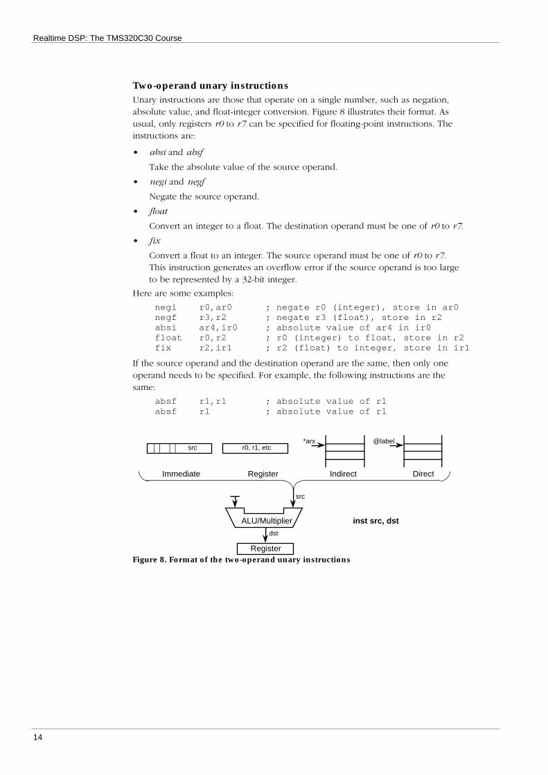
Two-operand unary instructionsUnary instructions are those that operate on a single number, such as negation,absolute value, and float-integer conversion. Figure 8 illustrates their format. Asusual, only registers r0 to r7 can be specified for floating-point instructions. Theinstructions are:
• absi and absf
Take the absolute value of the source operand.
• negi and negf
Negate the source operand.
• float
Convert an integer to a float. The destination operand must be one of r0 to r7.
• fix
Convert a float to an integer. The source operand must be one of r0 to r7.This instruction generates an overflow error if the source operand is too largeto be represented by a 32-bit integer.
Here are some examples:
negi r0,ar0 ; negate r0 (integer), store in ar0negf r3,r2 ; negate r3 (float), store in r2absi ar4,ir0 ; absolute value of ar4 in ir0float r0,r2 ; r0 (integer) to float, store in r2fix r2,ir1 ; r2 (float) to integer, store in ir1
If the source operand and the destination operand are the same, then only oneoperand needs to be specified. For example, the following instructions are thesame:
absf r1,r1 ; absolute value of r1absf r1 ; absolute value of r1
Immediate Indirect DirectRegister
src r0, r1, etc
Register
src
dst
ALU/Multiplier inst src, dst
*arx @label
Figure 8. Format of the two-operand unary instructions

Basic Instructions
15
Two-operand binary instructionsBinary instructions operate on two numbers and produce a result. The two-operand versions of these instructions operate store the result of the operation inthe same register as the second operand. The format of these instructions isillustrated in Figure 9.
This group of instructions includes the common arithmetic and bit-wise logicaloperations. Arithmetic operations are provided in both integer and floating-pointversions, logical operations are integer-only:
• addi, addf, mpyi and mpyf
Add or multiply two numbers.
• subi and subf
Subtract the first operand from the second.
• and, or, and xor
Take the bit-wise and, or, or exclusive-or of two integers.
Here are some examples:
addi 1,r0 ; add 1 to r0 (integer)subi @length,ar2 ; subtract the length variable
; from ar2mpyf r0,r0 ; square r0 (float)or 0400H,ir0 ; set bit 10 of ir0
Register
Immediate Indirect DirectRegister
Implied sourcesrc
dst
src r0, r1, etc
ALU/Multiplier inst src, dst
*arx @label
Figure 9. Format of the two-operand binary instructions
Realtime DSP: The TMS320C30 Course
16
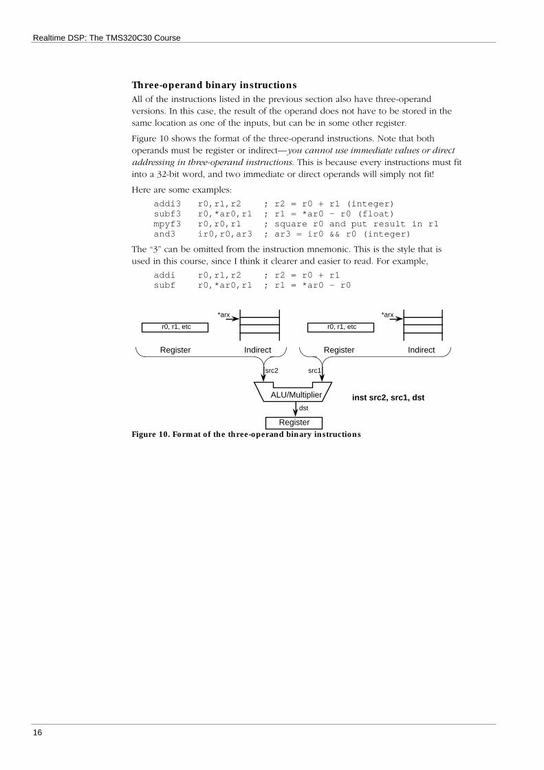
Three-operand binary instructionsAll of the instructions listed in the previous section also have three-operandversions. In this case, the result of the operand does not have to be stored in thesame location as one of the inputs, but can be in some other register.
Figure 10 shows the format of the three-operand instructions. Note that bothoperands must be register or indirect—you cannot use immediate values or directaddressing in three-operand instructions. This is because every instructions must fitinto a 32-bit word, and two immediate or direct operands will simply not fit!
Here are some examples:
addi3 r0,r1,r2 ; r2 = r0 + r1 (integer)subf3 r0,*ar0,r1 ; r1 = *ar0 – r0 (float)mpyf3 r0,r0,r1 ; square r0 and put result in r1and3 ir0,r0,ar3 ; ar3 = ir0 && r0 (integer)
The “3” can be omitted from the instruction mnemonic. This is the style that isused in this course, since I think it clearer and easier to read. For example,
addi r0,r1,r2 ; r2 = r0 + r1subf r0,*ar0,r1 ; r1 = *ar0 – r0
IndirectRegister
src1
r0, r1, etc
Register
dst
ALU/Multiplier inst src2, src1, dst
IndirectRegister
r0, r1, etc
src2
*arx*arx
Figure 10. Format of the three-operand binary instructions

Basic Instructions
17
Basic control flow instructionsControl flow instructions change program execution. The current program addressis contained in the program counter register, or pc. In this section, we will coverthe basic sub-routine call and branch (goto) instructions.
BranchThe branch instruction, br, causes program execution to jump to the specifiedaddress. The address is stored in the instruction word as 24 bits, so br can jump toanywhere in the TMS320C30’s 16-megabyte address range.
...+----- br nextup ; jump to nextup| ...| ...+-> nextup:
...Figure 11. The branch instruction
Subroutine call and returnThe sub-routine call instruction, call, causes execution to branch to a separatesubroutine. When it completes, the called subroutine must execute a sub-routinereturn instruction, rets, to return to the calling program.
Subroutine call and return is discussed in depth in the chapter on interfacing C andassembler code. Briefly, however, the call instruction causes the address of theinstruction just after the call (the return address) to be pushed onto the stack.Then, the address of the specified sub-routine is loaded into the program counter,so that program execution continues in that sub-routine. The destination address isstored as 24 bits in the instruction word, so the called sub-routine can be locatedanywhere in the TMS320C30’s 16 megabyte address space.
The rets instruction pops the return address off the stack and loads it into theprogram counter. Thus, the instruction executed after rets is the one following thecall. Because the stack is used, subroutine calls can be nested to an arbitrarydepth.
Caller Callee
... +-> process:
... | ...call process ----+ ...... <-------+ ...... | ...... +----- rets...
Figure 12. Subroutine call and return
The decrement-and-branch instructionThe decrement-and-branch instruction, db, decrements an auxiliary register andbranches to the specified location if the register becomes negative. This is usefulfor implementing for-loops in assembler. The auxiliary register is loaded with thenumber of times through the loop less one, and decremented at the end of theloop. Figure 13 illustrates this use of db.

Realtime DSP: The TMS320C30 Course
18
for ( ar0 = n-1; ar0 >= 0; ar0-- ){
...block...
}
...ldi @n,ar0 ; load the counter into ar0subi 1,ar0 ; set to n–1
+-> loop:| ...| block ; execute loop body n times| ...+----- db ar0,loop ; decrement and branch
...Figure 13. for-loop using the decrement-and-branch instruction
Note that this loop will always execute at least once.

19
Conditional Instructions
The TMS320C30 provides a complete set of conditional instructions and codes toaccess them. These codes and instructions are similar to those in conventional mi-cro-processors, with some additions:
• A flag for arithmetic underflow as well as overflow
• Latched underflow and overflow flags
• Conditional load, call, and return instructions as well as conditional branches
This chapter has two sections. The first lists the conditions, flags, codes andinstructions. The second gives examples of the use of conditional instructions. Youshould read quickly through the first section, and refer to its tables while studyingthe second section.
Condition flags, codes, and instructions
Condition flagsTable 1 lists the condition flags. These flags are contained in the status register,and are set and cleared according to the result of executing certain instructions.These flags can then be used to select the execution of conditional instructions—that is, instructions that execute only if the flags indicate a certain condition.
Table 1. Conditional Flags
Flag Meaning Instructions that setz Result is zero Integer and floating-point arithmetic, loadsn Result is negative Integer and floating-point arithmetic, loadsc Result set carry bit Integer arithmetic, rotate and shiftv Result overflowed Integer and floating-point arithmeticuf Result underflowed Floating-point arithmeticlv Latched overflow flag Integer and floating-point arithmeticluf Latched underflow flag Floating-point arithmetic
The z, n, c, v, and uf flags are set only until execution of the next instruction thataffects them. The lv and luf flags are latched—that is, they must be cleared explic-itly by the program.

Realtime DSP: The TMS320C30 Course
20
Instructions that affect condition flagsTable 2 lists the instructions that affect the condition flags.
Table 2. Instructions that affect condition codes
Instruction Codes affected Remarksabsf, addf, mpyf,negf, subf
n, z, v, uf, lv, luf Only if the instruction destination is one of R0 toR7. The three-operand versions of these instruc-tions (addf3 etc), and the parallel arithmetic-and-store versions (addf||stf etc) affect the flags inthe same way.
cmpf, cmpf3 n, z, v, uf, lv, luf The destination register must (obviously) be oneof r0 to r7.
absi, addc, addi,ash, mpyi, negi,subb, subi
n, z, c, v, lv(uf)
Only if the instruction destination is one of r0 tor7. The three-operand and parallel arithmetic-and-store versions of these instructions affect theflags in the same way.The uf flag is always set to zero.
cmpi, cmpi3 n, z, c, v, lv(uf)
The instruction destination can be any register.The uf flag is always set to zero.
lsh, rol, rolc, ror,rorc
n, z, c(v, uf)
Only if the instruction destination is one of r0 tor7. The three-operand and parallel arithmetic-and-store versions of these instructions affect theflags in the same way.The v and uf flags are always set to zero.
and, andn, or,xor, float, ldi, ldf,pop, popf
n, z(v, uf)
Only if the instruction destination is one of r0 tor7. The three-operand and parallel arithmetic-and-store versions of and, andn, os, and xor in-structions affect the flags in the same way.Parallel load and load-store instructions (ldi||ldi,ldi||sti etc) do not affect any flags.The v and uf flags are always set to zero.
tstb, tstb3 n, z(v, uf)
The instruction destination can be any register.The v and uf flags are always set to zero.
ldi||ldi, ldi||sti,ldf||ldf, ldf||stf,push, pushf, sti,stf, ldicond, ldf-cond
None None of these instructions affect any flags. Theyare listed here to remind you so!

Conditional Instructions
21
Condition codesCondition codes are attached to certain instructions. For example, the conditionalbranch instruction is listed below as bcond, where cond can be any one of thecodes listed in Table 3. For example, the “branch-if-zero” instruction is:
bz label ; branch of last result was zero
Table 3 lists the most commonly used condition codes. (For a complete list, seepage 10-11 of the TMS320C3X User's Guide.)
Table 3. Condition codes
Conditioncode
Flags Name Description
u Don’t care Unconditional The instruction is always executedlt n Signed less-
thenThe second operand of a subtract or comparewas less than the first operand
le n || z Signed less-or-equal
The second operand of a subtract or comparewas less than or equal to the first operand
gt !n && !z Signed greater-than
The second operand of a subtract or comparewas greater than the first operand.
ge !n Signed greater-or-equal
The second operand of a subtract or comparewas greater than or equal to the first operand.
eq z Equal The two operands were equalne !z Not equal The two operands were not equalz z Zero The result is zeronz !z Not zero The result is not zerop Positive The result is greater than zeron Negative The result is less than zero
nn Not negative The result is greater than or equal to zero
Conditional instructionsTable 4 lists all the instructions that can take a condition. Note that none of theconditional instructions can themselves affect the condition flags. For example, theinstruction
ldf @val,r3
will set the flags according to the value loaded into r3. However, a conditionalload will not set the flags:
ldfz @val,r3
The following instructions are therefore not the same:
ldf @val,r3 ; load val and set flagsldfu @val,r3 ; load val but do not set flags
Also, don’t forget that only loads into r0 to r7 set the flags!
Table 4. Conditional Instructions
Instruction Descriptionldicond, ldfcond Load from memory into a register conditionallybcond, bcondd Standard and delayed conditional branches
dbcond, dbcondd Standard and delayed decrement-and-branchcallcond, retscond, reticond Conditional sub-routine call and return
trapcond Conditional software trap

Realtime DSP: The TMS320C30 Course
22
Conditional instruction examplesIn this section, we will study how to use the conditional instructions to implementparticular C constructs and expressions.
if-thenFor this construct, program execution jumps past the code block if the condition isnot true. Note that the condition code must be the inverse of what you mightexpect. That is, the block of instructions is to be executed only if the comparisontest shows that r0 ≥ 0.0. Therefore, the branch is to be executed if this is not thecase, hence the blt.
if ( r0 ≥ 0.0 ){
...block...
}
...cmpf 0.0,r0 ; compare r0 with 0.0
+----- blt label1 ; skip past instructions| ...| block ; do block of instructions| ...+-> label1:
...Figure 14. Assembler equivalent of if-then construct

Conditional Instructions
23
if-then-elseIn this case, there are two code blocks. The first is skipped if the condition is nottrue. Note the branch at the end of the first block.
if ( r1 > r0 ){
...block1...
}else{
...block2...
}
...cmpf r0,r1 ; compare r1 against r0
+----- ble label1 ; branch if r1 ≤ r0| ...| block1 ; do if r1 > r0| ...
+-+----- b label2 ; skip past second block | | | | | +-> label1: | ... | block2 ; do if !(r1 > r0) | ... | +---> label2:
...Figure 15. Assembler equivalent of if-then-else construct
whileA while-loop requires a test-and-branch at the beginning of the loop in case thecondition is already true. Then, a test-and-branch is required at the end of eachloop.
while ( r0 ≥ 0.0 ){
...block...
}
...cmpf 0.0,r0 ; compare r0 with 0.0
+------- blt done ; branch past loop | +-> loop: | | ... | | block ; do loop body | | ... | | cmpf 0.0,r0 ; end-of-loop test | +----- bge loop ; ..and loop again +---> done:
...Figure 16. Assembler equivalent of while loop

Realtime DSP: The TMS320C30 Course
24
while loop with limit counterThe decrement-and-branch instruction can be used to effect to implement while-loops that must only execute a certain maximum number of times. For example,suppose one were attempting to evaluate a series approximation function, butwanted to impose a limit on execution time. Figure 17 illustrates this code.
count = 0;while (r0 > eps && count < limit){
make_new_r0;count++;
}
...ldi @_limit,ar0 ; load countersubi 1,ar0
+------- bn done ; exit if limit was zero | | ldf @_eps,r1 | cmpf r0,r1 ; test +------- ble done ; already satisfies test | | +-> loop: | | make_new_r0; | | cmpf r0,r1 | +----- dbgt ar0,loop ; loop until limit or eps | +---> done ...Figure 17. while-loop with count
Select maximumThe TMS320C30's conditional load instructions can sometimes eliminate the needfor conditional branches. Since a (non-delayed) branch takes four cycles, this canbe very effective. The code in Figure 18 selects the maximum of two numbers.
if (r1 > r2)r0 = r1;
elser0 = r2;
...ldf r1,r0 ; preload r0 with r1cmpf r1,r2 ; compare r2 with r1ldfge r2,r0 ; load r2 if greater or eq...
Figure 18. Selecting the maximum of two numbers

Conditional Instructions
25
Calculating signumFigure 19 uses conditional loads to calculate the signum of a number. Note thatthis code works only because the conditional loads do not change the conditionflags.
if (r0 > 0)r0 = 1;
else if (r0 < 0)r0 = -1;
elser0 = 0;
...cmpf 0,r0 ; test r0ldip 1,r0 ; -> 1ldin -1,r0 ; -> -1ldiz 0,r0 ; -> 0...
Figure 19. alculating the signum of a number
Conditional call and returnWhen working in the C environment, conditional call and return instructions aremostly limited in use to simple functions. Because C-callable functions tend torequire additional code before calling (to stack) and before returning (to restoreregisters and the frame pointer), only the most minimal C-callable function lendthemselves to direct use of callcond and retscond instructions.
However, in certain situations, good use can be made of these instructions. Figure20 illustrates a conditional call dependent on the value of a bit in a register:
if (r0[14])process(r1);
...pushf r1 ; push argumenttstb 14,r0callnz _process ; call this if bit setsubi 1,sp ; adjust stack...
Figure 20. Conditional call

27
More On Addressing
This chapter describes the addressing modes of the TMS320C30 in more depth.Some special topics (modulo and bit-reversed addressing) are left until Chapter .
Indirect addressingAs we have already seen, the TMS320C30 allows you to access memory via anaddress stored in one of ar0 to ar7, analogously to a C pointer. In Figure 4 ofChapter 3, you can see that these registers have two arithmetic units—calledARAUs—independent of the main data ALU. The ARAUs give the TMS320C30 verypowerful indirect addressing features.
Indexed addressingAn indirect memory access can be indexed relative to an address contained in anauxiliary register. For example, the instruction
ldi *+ar0(3),r0
loads the word at (contents of ar0) + 3 into r0. The value 3 is referred to as thedisplacement: it is contained in eight bits of the instruction word, and cantherefore be any value between 0 and 255.
The displacement can be subtracted from the auxiliary register as well as added:
addf *-ar2(1),r2
The equivalent C constructions are:
x = *(p+3);y += *(q-1);
where x and y are variables, and p and q are pointers.
Indexed addressing for structure access
Indexed addressing is an ideal match for access to C-style structures. For example,suppose you had the following C structure (defined in a header file):
typedef struct {int size;float seed;float *data;
} MyStruct;
To read or modify this structure in an assembler routine, pass a pointer to thestructure to the assembler routine:
MyStruct mydata;...myasmfunc( &mydata );
Now, the assembler routine can access the elements of the structure by usingindexed addressing off the structure pointer. To ensure portability, assemblerdirectives are used to define the same structure in assembler (see the TMS320Floating-Point DSP Assembly Language Tools User's Guide):
MyStruct .struct ; declare the structure namesize .int ; declare the fieldsseed .floatdata .wordsizeofMyStruct .endstruct ; so we know its size
Realtime DSP: The TMS320C30 Course
28
Note that the data field is defined as a word, not as a float, because it is a pointer,not a floating-point number. On the TMS320C30, the .word directive is the same asthe .int and .long directives.
Now, suppose that the myasmfunc routine first loads the pointer to mydata intoregister ar1 (see Chapter 6). Instructions in myasmfunc to access mydata mightinclude:
...ldi *+ar1(MyStruct.size),ar2 ; load size into ar2...subrf *+ar1(MyStruct.seed),r0 ; subtract r0 from seed...sti ar0,*+ar1(MyStruct.data) ; update data pointer...
(Note again that the data pointer is an integer, not a float.)
Note on displacements
The displacement is eight bits for two-operand instructions. Three-operand binaryinstructions (see Chapter 3) and parallel instructions (see Chapter 7) allowdisplacements of only zero or one. Thus, the following instruction is illegal:
addf *+ar1(3),r0,r1
The index registersThe use of immediate displacements as described in the previous section has somelimitations. In particular, displacements
i) are limited to 255,
ii) can only be zero or one for three-operand and parallel instructions, and
iii) must be constant.
These limitations can be overcome with the index registers, ir0 and ir1. Instead ofspecifying an immediate value, specify one of the index registers. For example,
ldf *+ar2(ir0),r2addi *-ar0(ir1),r3,r0
Obviously, ir0 or ir1 must already contain some meaningful value! In general, theindex registers are used more often with post-modify and pre-modify addressing,as described in the following sections, than with indexed addressing.
Post-modify addressingThe TMS320C30 supports C-style pointer incrementing directly in hardware. Forexample, the pointer update in the C statement
x = *p++;
is done by the C30 instruction
ldf *ar0++,r0
That is, the value at the location pointed to by ar0 is loaded into r0, and ar0 isthen incremented by one (by one of the ARAUs). However, the TMS320C30assembler can do more than C:
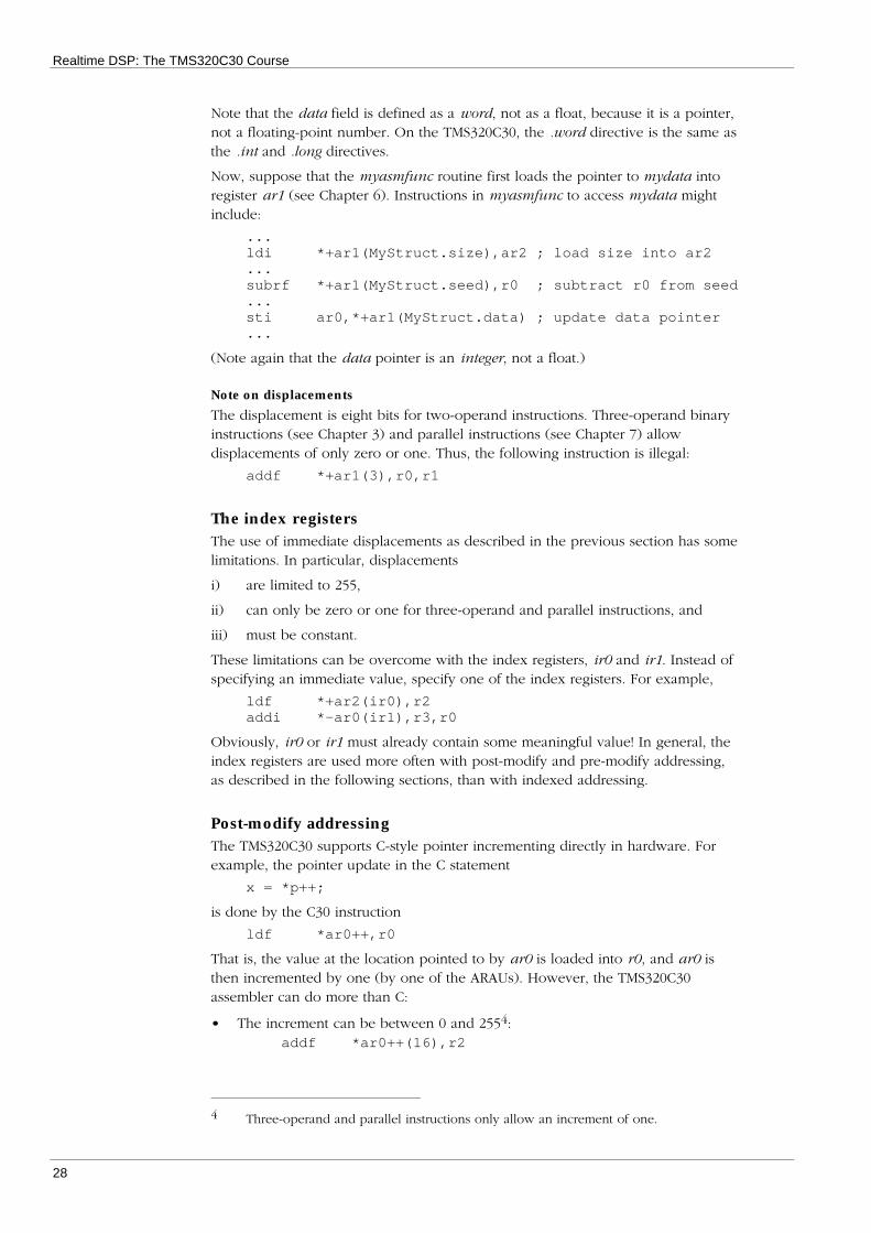
• The increment can be between 0 and 2554:addf *ar0++(16),r2
4 Three-operand and parallel instructions only allow an increment of one.

More on Addressing
29
• The increment can be an index register:sti r3,ar2++(ir0)
The increment can also be negative:
and *ar1--(2),r1stf r4,*ar0--(ir1)
Pre-modify addressingIn C, the increment can also be done before the read from or write to the pointed-to memory location:
x = *++p;
That is, the pointer is first updated, and the updated value is then used to addressmemory. The TMS320C30 supports pre-modify addressing in all the same modes aspost-modify addressing. For example:
ldf *++ar4(2),ar0addf *++ar0,r0,r1 ; note increment is one herestf r1,*--ar3(ir0)
Usage of post-modify and pre-modify addressingMuch of the speed of the TMS320C30 for signal processing applications comesfrom effective use of addressing and index registers. For example, a commonsignal processing operation is to “window” a block of samples:
xsi = xsi × wi for 0 ≤ i < n
where xs is the input vector and w is the window vector. This operation can beimplemented using a decrement-and-branch instruction (see Chapter 3), as shownin Figure 21. In this code, it is assumed that ar0 points to xs, ar1 points to w, andr0 contains the length of the vectors, n.
...ldi r0,ar2 ; load countersubi 1,ar2 ;
loop:mpyf *ar0,*ar1++,r0 ; multiply..stf r0,*ar0++ ; store..db ar2,loop...
Figure 21. Windowing using post-modify addressing
In this example, only one of the operands to mpyf is incremented; in general,however, both can be incremented, since there are two ARAUs. In Chapter 7, wewill see how this loop can be made several times faster.

Realtime DSP: The TMS320C30 Course
30
The memory mapBefore we go any further, it would be helpful to learn a little more about theTMS320C30’s memory map. Figure 22 shows how the 16-megaword address rangeis partitioned.
0h
BFh
800000h
802000h
804000h
806000h
808000h
809800h809C00h80A000h
0FFFFFFh
Hardware interrupt vectors (12)Software interrupt vectors (32)
Reserved (Total 192)
Main bus (STRB)
Expansion bus, MSTRB active (8 k)
Reserved (8 k)
Expansion bus, IOSTRB active (8 k)
Reserved (8 k)
Memory-mapped registers (6 k)
RAM block 0 (1 k)RAM block 1 (1 k)
Main bus (STRB)
16 MBytes
0FFFh
0h
BFh
InternalROMin micro-computermode
Features:• 24-bit (16 MWord) address space• Two blocks of internal RAM• Memory-mapped peripheral I/O
Figure 22. The TMS320C30 memory map
Most of the address space is assigned to the main off-chip bus, and is usually usedfor general-purpose external memory. Depending on the design of the particularboard, this memory may be a combination of static and dynamic memory. Staticmemory usually has no wait states (that is, no speed penalty), while dynamicmemory typically introduces one or two additional cycles per access. Of course,very few systems will actually use the whole 16 megaword address space—theTMS320C30 Evaluation Module, for example, uses only the lowest 16 kilowords.
The TMS320C30 also has the following special memory regions:
• The interrupt vectors (00h to 0BFh)
These locations contain pointers to interrupt service routines, and aredescribed in Chapter 10.

More on Addressing
31
• The expansion bus (800000h to 802000h and 804000h to 806000h)
The TMS320C30 (but not the TMS320C31) has a second set of data andaddress busses, called the expansion bus. This bus is used for externalperipheral devices. Because its usage depends only on the particular hardwareconfiguration, we will not deal further with this bus in this course.
• The on-chip peripherals (808000h to 809800h)
The TMS320C30 has a number of on-chip peripherals, including two serialports, two timers, and a DMA controller. The control registers for theseperipherals, as well as register to control the operation of the main andexpansion busses, are contained within this memory region. Programming theperipherals is dealt with in Chapter 9.
• The internal memory blocks (809800h to 80A000h)
The TMS320C30 has two consecutive blocks of internal memory, of 1k wordseach. These memory blocks are important in achieving full performance, sincethey support an instruction read and two data accesses in a single cycle. Waysof allocating internal memory are covered in Chapter 11, while ways ofmaximising device performance are covered in Chapter 12.
Direct addressingDirect addressing allows memory locations to be addressed by name. Thefollowing code illustrates access to a named memory location:
...
.int count ; declare the variable
...ldi @count,r0 ; read the variable...
This form of addressing can also be used to access C variables. For example,suppose current_ptr is defined in a C file as follows:
float *current_ptr;
An assembler file can access this variable as follows:
...
.global _current_ptr ; declare reference to variable
...addi @_current_ptr,r2 ; access variable...
Note the additional underscore in front of the variable name: all C variables andfunctions require a prepended underscore when referenced from assembler.
The data page pointerFor direct addressing, the memory address is contained in the instruction word.Because of instruction encoding limitations, this address can only be 16 bits long,while the TMS320C30 has a 24-bit address range. As shown in Figure 5 of Chapter3, the TMS320C30 solves this problem by using the lowest 8 bits of a specialregister, the data page pointer, or dp register, to specify bits 16 to 23 of theeffective address. These eight bits specify one of 256 memory “pages,” each ofwhich is 64 kilowords long.
The effective address (that is, the actual address put onto the address bus) istherefore a combination of the dp register and the lower 16 bits of the variable’saddress. dp must of course be set to the appropriate value before-hand—this isdone with the ldp (load data page) instruction:

Realtime DSP: The TMS320C30 Course
32
ldp _current_ptraddi @_current_ptr,r2
Unless it is known that all variables are contained within the same data page, eachand every direct memory access must be preceded by a ldp instruction.
The small and large memory modelsObviously, loading dp before each direct memory access introduces a rather largeoverhead. In many systems, all variables can be contained within one data page;dp need be loaded only once at the beginning of the program. The TMS320C30 Ccompiler thus has two “memory models” (similar to the memory models used incompilers for 8086-series microprocessors): large and small.
The small memory model requires that all directly-addressable data fits into asingle 64 kiloword page. This is the default mode assumed by the C compiler.Assembler code that is linked with C code compiled in the small memory modelneed not (in fact, must not!) load dp, since dp is set up by compiler-generated5
initialisation code.
The large memory model allows directly-addressable data to be located anywherein memory. The C compiler generates a ldp instruction before every direct memoryaccess; all code linked with code compiled in the large memory model must bewritten and/or compiled for the large memory model. The large memory model isspecified with the –mb option to the compiler or assembler.
How to cope with both memory models
Obviously, you do not want to write two different versions of every assemblerfunction you write: one for the small memory model, and one for the largememory model. You can write code that caters for both models by using the.BIGMODEL assembler flag: this flag is set if code is assembled with the –mboption. For example:
.if .BIGMODELldp _current_ptr.endifaddi @_current_ptr,r2
Note that many assembler routines will not need to insert these kinds of assemblerdirectives: if a routine receives all its data via its arguments, it may not even needto use the direct memory addressing mode. This type of routine conforms moreclosely to the spirit of modular programming.
How to avoid the large memory model
Note that the 64 kiloword restriction of the small memory model applies only todirectly addressable data—that is, data which is accessed using the directaddressing mode. You can have much more than 64 kwords of data in yourprogram, by using indirect addressing. In other words, allocate large memoryarrays using the C heap—the standard routines are malloc() and free(). Thepointers to these large arrays will be directly addressable, but the data itself isaccessed using indirect addressing. Note however that it is not sufficient that allvariables (not including heap-allocated variables) fit into 64 kilowords—they mustall fit into one data page.
See Chapter 11 for more detailed information on allocating and using memory.
5 Well, not strictly true: dp is set up by the initialisation function boot.asm contained inthe C run-time support (RTS) library).
33
C-Assembler Interfacing
Although the TMS320C30 C compiler provides the convenience and high-levelabstractions of the C language for real-time DSP, the compiler is less efficient thanhand-coded assembler. In particular, time-critical sections of code—such as innerprogram loops and computationally-intensive algorithms—are usually coded inassembler. Thus, we need to be able to call assembler programs from C, and viceversa.
In most of this course, we will write all assembler functions to be “C-callable.” Inother words, they conform to the C compiler’s function calling interface. C-callablefunctions are, of course, always produced by the C compiler. Thus, C-callablefunctions can be written in assembler or C, and called from assembler or C.
As our example, we will use the function whither, and show how to call this
function from assembler, and how to write a C-callable version of it in assembler.whither has the C prototype:
floatwhither( int size, float seed );
The stackSince the C compiler's default argument-passing mechanism uses the run-timestack, some understanding of the C stack is required before dealing with functioninterfaces.
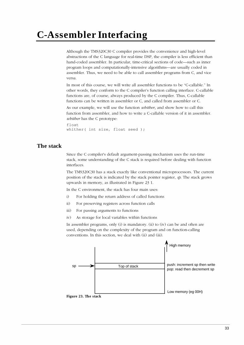
The TMS320C30 has a stack exactly like conventional microprocessors. The currentposition of the stack is indicated by the stack pointer register, sp. The stack growsupwards in memory, as illustrated in Figure 23 1.
In the C environment, the stack has four main uses:
i) For holding the return address of called functions
ii) For preserving registers across function calls
iii) For passing arguments to functions
iv) As storage for local variables within functions
In assembler programs, only (i) is mandatory. (ii) to (iv) can be and often areused, depending on the complexity of the program and on function-callingconventions. In this section, we deal with (ii) and (iii).
Low memory (eg 00H)
High memory
Top of stacksp push: increment sp then writepop: read then decrement sp
Figure 23. The stack

Realtime DSP: The TMS320C30 Course
34
Push and pop instructionsThere are four instructions for storing and loading data to and from the stack:push, pop, pushf, and popf. push increments the stack pointer, and then writes thespecified 32-bit integer register to the top of the stack. pop loads a 32-bit integerregister with the value at the top of the stack, and then decrements the stackpointer.
pushf and popf are exactly the same, except that they store and load 32-bitfloating-point values from R0 to R7.
These four instructions are usually used for items (ii) and (iii) above—that is, topreserve registers across function calls, and to pass arguments on the stack.
Preserving registersFigure 24 illustrates preserving registers. As we will see in the next section, the Ccompiler requires that all functions preserve certain registers. If, for example, R4and R5 are used in the body of the function, then they must be saved on the stackon entry to the function, and restored before returning. (For the moment, ignorethe code dealing with the fp register.)
whither:push fpldi sp,fppush r4 ; save r4 and r5 (as integer)push r5...... ; body uses r4 and r5...pop r5 ; restore r4 and r5pop r4pop fprets
Figure 24. Preserving registers (1)
Stacking function argumentsFigure 25 illustrates how function arguments are stacked. The function whither hasone integer argument and one floating-point argument—the code shown assumesthat they are contained in registers R1 and R0 respectively. After the return fromwhither, the stack pointer is restored to its original value with a subtractinstruction.
...pushf r0 ; second argpush r1 ; first argcall whither ; call itsubi 2,sp ; restore stack pointer...
Figure 25. Passing stack arguments
Saving 40-bit floatsThe pushf instruction only saves a 32-bit float. However, R0 to R7 hold 40-bitfloats. There are some situations in which the full 40 bits must be saved. Inparticular:

C-Assembler Interfacing
35
• The C compiler requires that R6 and R7 are preserved as 40-bit floats.
• Any of R0 to R7 used in an interrupt service routine must be saved as a 40-bitfloat.
A two-instruction sequence is required to push or pop a 40-bit float. To push R0:
push r0 ; push mantissapushf r0 ; push 32-bit float
To pop R0:
popf r0 ; pop 32-bit floatpop r0 ; overwrite mantissa
Figure 26 shows the code for whither if R6 is also used in the function body.
whither:push fpldi sp,fppush r4 ; save r4 and r5 (as integer)push r5push r6 ; save r6 (as float)pushf r6...... ; body uses r4 and r5...popf r6 ; restore r6pop r6pop r5 ; restore r4 and r5pop r4pop fprets
Figure 26. Preserving registers (2)
Setting the stack size and locationThe size and location of the memory allocated for use as the stack is set by thelinker. The default size of the stack is 1024 words. It can be changed by supplyingthe "-stack" option to the linker (or after "-z" when invoking the cl30 shell):
lnk30 main.obj whither.obj c.cmd -o prog.out -stack 2048
Usually, however, it is easier to add a line to the linker command file. Forexample, add the line
-stack = 512
to c.cmd.
The stack uses the special memory section called ".stack" The location of thissection is set in the linker command file. If you examine the linker command filec.cmd, you will see a line like:
.stack > RAM1
which puts the stack into RAM block 1. To put the stack into external RAM (whichyou have to do if you made the stack larger, for example), change this line to:
.stack > SRAM
The C calling interfaceSuccessfully interfacing C and assembler code is mainly a matter of understandingthe function calling convention. The main points concerning the function interfaceare as follows:

Realtime DSP: The TMS320C30 Course
36
i) The compiler passes arguments on the C stack. Arguments are pushed ontothe stack in reverse order—that is, the last argument is pushed first.
The compiler also has an option to pass arguments in registers, but discussionof this is deferred to a more advanced section.
ii) All arguments are passed as 32-bit values. Integers, floats, and pointers arepassed as-is. Structures are pushed onto the stack element-by-element.
iii) All float, integer and pointer results are return in R0. void functions do not setR0 to any particular value. Structure results are covered in a later section.
Stack frames and the frame pointerWhen a function is called, it creates a stack frame. This is simply the term for thearea of the stack used for that function call. Register AR3 is reserved by thecompiler as a pointer to this area. Understanding the structure of the frame iscrucial to writing C-callable functions. To make code easier to read, a mnemonic isusually defined for AR3—the following line should appear new the beginning ofyour assembler source file:
fp .set ar3 ; use ar3 as the frame pointer
The example codeFigure 27 shows the sequence of instructions when a function is called. Theconstructed stack frame is illustrated in Figure 28. This illustrates the full use of thestack during a function-call sequence, in which the stack frame has three parts:
• Function arguments
• Return address
• Saved frame pointer
• Local variables
• Saved registers
To illustrate the use of the local variable part, we will assume that whither has twolocal variables:
floatwhither( int size, float seed ){
int count;float divisor;...
}
Many assembler functions do not need all of these fields. A more minimal stackframe that can be used be many assembler functions is described later.

C-Assembler Interfacing
37
Caller Callee
1 ...2 +-> pushf r03 | push r14 | call whither5 | whither:6 | +-----> push fp7 | | ldi sp,fp8 | | +---> addi 2,sp9 | | | +-> push r410 | | | | push r511 | | | | push r612 | | | | pushf r613 | | | | ...14 | | | | ldi *-fp(2),ar015 | | | | ldf *-fp(3),r016 | | | | ...17 | | | | sti ar0,*+fp(1)18 | | | | stf r0,*+fp(2)19 | | | | ...20 | | | | popf r621 | | | | pop r622 | | | | pop r523 | | | +-> pop r424 | | +---> subi 2,sp25 | +-----> pop fp26 | rets27 +-> subi 2,sp28 ...29 addf r0,r230 ...Figure 27 Calling a C-callable function
sp
Return addressSaved frame pointer
count
sizeseed
fp
Saved registers
Scratch area
*–fp(2)*–fp(3)
*+fp(1)
*+fp(2)
whither: push fp ldi fp,sp push ... .. .. *-fp(2) .. *-fp(3) .. pop .... pop fp rets
divisor
Figure 28. The stack frame
The function call sequenceThe steps in calling a function are as follows:
Line 1: Initially, the stack contains the stack frame of the caller. As far asthe call to whither goes, we only care about what goes on thestack above this point.
Lines 2 and 3: The caller pushes the arguments onto the stack.
Line 4: The call instruction pushes the return address onto the stack.
Line 6: The callee saves ar3 (the old frame pointer) on the stack.

Realtime DSP: The TMS320C30 Course
38
Line 7: The callee copies the stack pointer into the frame pointer register.This is the current frame pointer, and is used to access anyvariable in the callee's stack frame.
Line 8: The callee reserves space in the local stack frame for localvariables.
Lines 9 to 12: The callee pushes registers that must be preserved onto the stack.
Accessing argumentsThe arguments to the function are accessed by using indirect addressing off theframe pointer. The first argument to the function is two locations below FP, thesecond is three locations below, and so on. In Figure 27, the arguments are justloaded into the AR0 and R0 registers:
Line 14: Load the first argument (size) into AR0.
Line 15: Load the second argument (seed) into R0.
Of course, the arguments can be used directly as operands to other instructions,and over-written with new values. For example, the following code sequencedoubles the size argument, and stores the new value back into the size variable onthe stack:
ldi *-fp(2),r0 ; load sizeaddi *-fp(2),r0 ; double itsti r0,*-fp(2) ; save new value
Accessing local variablesThe local variables are also access relative to the frame pointer. They start onelocation above the frame pointer:
Line 17: Store R1 into the first local variable (count).
Line 18: Store R0 into the second local variable (divisor).
As for the function arguments, the local variables can be read and written like anyother memory locations by using the register offset addressing mode.
Return sequenceOnce the assembler function has finished its processing, the stack frame isdeconstructed in the reverse order to which it was built:
Lines 20 to 23: Preserved register are popped off the stack, in the reverse order towhich they were popped.
Line 24: The stack pointer is adjusted to remove the local variables.
Line 25: The frame pointer register is restored to its original value.
Line 26: The return address is popped of the stack and loaded into theprogram counter. The next instruction executed is thus the onefollowing the call instruction.
Line 27: The caller restores the stack pointer to its initial value.
After execution of line 27, the stack is back in the state it was in before the call towhither was initiated.
Important ruleThe stack must always be restored to its original state. This is important enough toput it into a box:
Rule: The stack must always be restored to its initial value.

C-Assembler Interfacing
39
Figure 27 shows how stack operations always occur in pairs. Values are pushedonto the stack at one point, and later are popped off the stack or the stack pointeradjusted to discard them. These pairs must always be properly nested to maintainthe stack correctly.
After the return, the caller can use the result of the called function (line 24). For avoid function, the caller just ignores the value of R0.
Register usageAlthough the example code for whither saved several register, many assemblerfunctions will not need to save any registers at all (other than the frame pointer).The C compiler only requires that the registers listed in Table 5 are preservedacross function calls. This has three ramifications on your assembler code:
1. A called function needs to save only these registers on the stack (and only ifthey are used, of course). Many assembler functions only need a fewregisters—for example, a function that uses R0 to R3, AR0 to AR2, and IR0,needs to save only the frame pointer (AR3) on the stack.
2. A caller can be sure that registers listed in Table 1 will not be corrupted bycalls to other functions. Thus, variables that are used frequently throughout thelife of a function are usually put into these registers.
3. If a caller wants any values in any other register to be preserved across afunction call, then it must save the variable itself with a push/pop pair aroundthe function call.
Note that registers R6 and R7 must be saved and restored with push/pushf andpopf/pop instruction pairs, as described earlier.
Table 5. Registers preserved across function calls
Register Compiler usager4, r5 Integer register variablesr6, r7 Floating-point register variablesar3 Frame pointer (fp)ar4 to ar7 Pointer register variablessp Stack pointerdp Data page pointer (small model only)
A minimal calling interfaceThe previous calling interface example described used the full stack frame createdby the C compiler. When using assembler mainly as a means of ensuring fastexecution of critical code, many functions do not use the full stack frame: Inparticular:

Realtime DSP: The TMS320C30 Course
40
• Hand-coded assembler functions tend to use registers for storing temporaryvalues in. The local variables part of the stack frame is therefore not required,and lines 8 and 24 of Figure 27 are omitted.
• Assembler functions often need only a few registers, and so do not need topreserve any registers other than the frame pointer. Lines 9—12 and 20—23 ofFigure 27 are omitted.
• Functions with no arguments may not even need a frame pointer. Lines 6, 7,and 25 of Figure 27 are omitted.
Figure 29 shows whither with no local variables and no need to preserve anyregisters. Figure 30 shows a function with no arguments. This example simplyincrements the global variable access_count.
_whither:push fpldi sp,fp...ldi *-fp(2),ar0ldf *-fp(3),r0...pop fprets
Figure 29. Minimal C-callable function
_access:ldp _access_countldi @_access_count,r0addi 1,r0sti r0,@_access_countrets
Figure 30. Even more minimal C-callable function

41
Advanced Instructions
Although the title of this chapter is “Advanced Instructions,” the instructionspresented here are not necessarily any more difficult to use than those presentedpreviously! Rather, these instructions are those that distinguish the instruction setof the TMS320C30 (and other DSP microprocessors) from conventionalmicroprocessors.
The topics covered in this chapter are delayed branches and repeat instructions,which reduce the overhead of branching and looping; parallel instructions, whichenable better utilisation of the TMS320C30’s internal resources, and the use ofthese features together.
Delayed branches
The TMS320C30 pipelinePreviously, we have seen how loops can be built using decrement-and-branchinstructions or conditional branches. However, the standard branching instructionsare quite expensive: four cycles, whether the branch is taken or not. This isbecause the TMS320C30 has a four-stage pipeline: Fetch, Decode, Read, andExecute. Each stage is operating on a different instruction—that is, while oneinstruction is being executed, the following one is having its operands read fromregisters of memory, and so on.
When a branch instruction is decoded, the TMS320C30 stops reading instructions,because it does not want to inadvertently execute any portion of the instructionfollowing the branch instruction inadvertently. This is called “flushing” thepipeline. When the branch instruction is executed, the program counter is set theappropriate value, and the TMS320C30 starts filling the pipeline again from theinstruction at that address. Hence the additional cycles taken to execute a standardbranch (whether the branch is taken or not). See Chapter 10 of the TMS320C3XUser’s Guide for detailed information on pipeline operation.
Delayed branchesTo eliminate this branching overhead, the TMS320C30 has a set of special delayedbranch instructions. Each of the three types of branching instruction has a delayedversion:
• brd
Delayed unconditional branch
• bcondd
Delayed conditional branch
• dbcondd
Delayed decrement-and-branch with condition
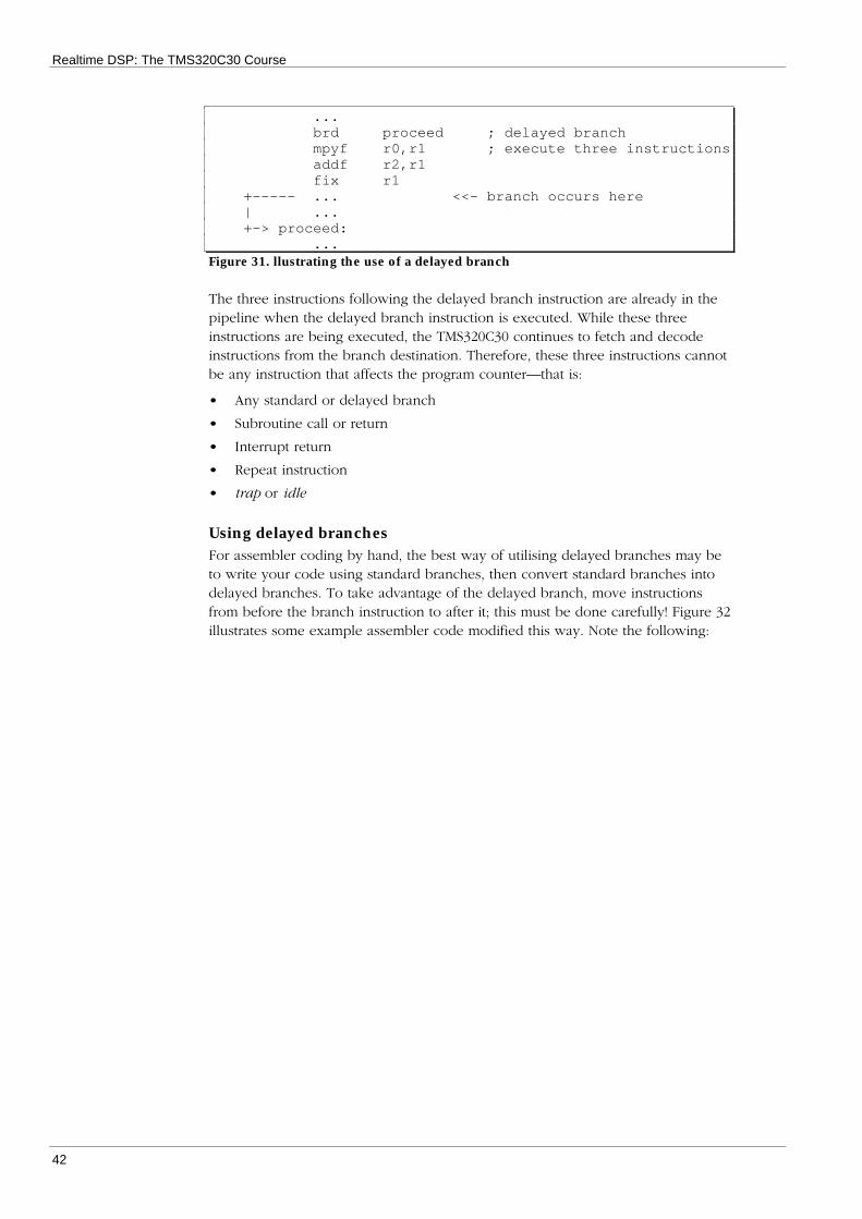
Delayed branches execute the three instructions following the branch instruction,and then the branch is taken. The branch thus effectively takes only one cycle.Figure 31 illustrates the use of a delayed branch. The three instructions followingthe branch (mpyf, addf, and fix) are executed before the branch is taken.
Realtime DSP: The TMS320C30 Course
42
...brd proceed ; delayed branchmpyf r0,r1 ; execute three instructionsaddf r2,r1fix r1
+----- ... <<- branch occurs here| ...+-> proceed:
...Figure 31. llustrating the use of a delayed branch
The three instructions following the delayed branch instruction are already in thepipeline when the delayed branch instruction is executed. While these threeinstructions are being executed, the TMS320C30 continues to fetch and decodeinstructions from the branch destination. Therefore, these three instructions cannotbe any instruction that affects the program counter—that is:
• Any standard or delayed branch
• Subroutine call or return
• Interrupt return
• Repeat instruction
• trap or idle
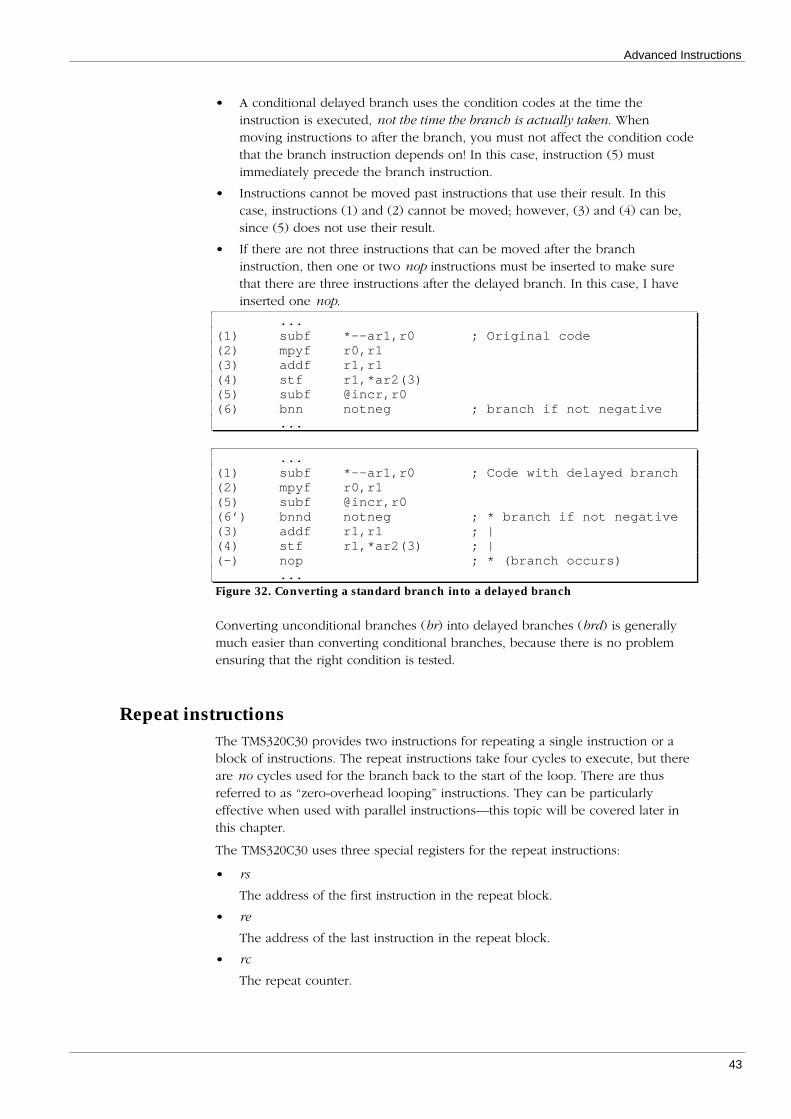
Using delayed branchesFor assembler coding by hand, the best way of utilising delayed branches may beto write your code using standard branches, then convert standard branches intodelayed branches. To take advantage of the delayed branch, move instructionsfrom before the branch instruction to after it; this must be done carefully! Figure 32illustrates some example assembler code modified this way. Note the following:
Advanced Instructions
43
• A conditional delayed branch uses the condition codes at the time theinstruction is executed, not the time the branch is actually taken. Whenmoving instructions to after the branch, you must not affect the condition codethat the branch instruction depends on! In this case, instruction (5) mustimmediately precede the branch instruction.
• Instructions cannot be moved past instructions that use their result. In thiscase, instructions (1) and (2) cannot be moved; however, (3) and (4) can be,since (5) does not use their result.
• If there are not three instructions that can be moved after the branchinstruction, then one or two nop instructions must be inserted to make surethat there are three instructions after the delayed branch. In this case, I haveinserted one nop.
...(1) subf *--ar1,r0 ; Original code(2) mpyf r0,r1(3) addf r1,r1(4) stf r1,*ar2(3)(5) subf @incr,r0(6) bnn notneg ; branch if not negative
...
...(1) subf *--ar1,r0 ; Code with delayed branch(2) mpyf r0,r1(5) subf @incr,r0(6’) bnnd notneg ; * branch if not negative(3) addf r1,r1 ; |(4) stf r1,*ar2(3) ; |(-) nop ; * (branch occurs)
...Figure 32. Converting a standard branch into a delayed branch
Converting unconditional branches (br) into delayed branches (brd) is generallymuch easier than converting conditional branches, because there is no problemensuring that the right condition is tested.
Repeat instructionsThe TMS320C30 provides two instructions for repeating a single instruction or ablock of instructions. The repeat instructions take four cycles to execute, but thereare no cycles used for the branch back to the start of the loop. There are thusreferred to as “zero-overhead looping” instructions. They can be particularlyeffective when used with parallel instructions—this topic will be covered later inthis chapter.
The TMS320C30 uses three special registers for the repeat instructions:
• rs
The address of the first instruction in the repeat block.
• re
The address of the last instruction in the repeat block.
• rc
The repeat counter.

Realtime DSP: The TMS320C30 Course
44
All of these registers can be used as general-purpose integer registers when notbeing used for repeat instructions.
Single-instruction repeat
The rpts instruction executes the instruction following it the specified number oftimes. It can be used to sum an array of 32 integers as show in Figure 33.
...ldi 0,r0rpts 31 ; loop next instruction
+-> addi *ar0++,r0 ; repeat 32 times...
Figure 33. Single-instruction repeat
The argument to rpts must be one less than the number of times the followinginstruction is to be repeated. In this example, the operand is an immediate value,but in general, it can use any of the operand addressing modes (immediate,register, direct, or indirect).
Block repeat
The rptb instruction repeats a block of instructions; the number of iterations isequal to the value in rc plus one. Its operand is the 24-bit address of the lastinstruction in the block, so the rc register must be set up explicitly beforeexecuting the rptb. The code in Figure 34 sums one complex vector into another.ar0 and ar1 point to the vectors; r0 contains the length of the vectors.
...ldi r0,rc ; set up loop countersubi 1,rc
rptb loop ; start loop+-----> addf *ar0++,*ar1,r0 ; real part| stf r0,*ar1++| addf *ar0++,*ar1,r0 ; imaginary part| loop:+----- stf r0,*ar1++
...
...Figure 34. Block repeat
Parallel InstructionsTo allow efficient utilisation of the TMS320C30’s internal parallelism, its instructionset includes a number of “parallel” instructions, of which there are three groups:
• Parallel multiply and add/subtract
• Parallel load and/or store
• Parallel arithmetic and store
Parallel multiply and add/subtractThis instruction is provided to allow both the internal multiplier and ALU to beused simultaneously. This is in fact the only instruction that allows the TMS320C30to achieve its peak floating-point rating of 33 MFLOPS (at 33 MHz clock rate).6
6 You can see that the claimed floating-point performance of the TMS320C30 in themanufacturer’s literature is in fact a very unrealistic figure for almost all applications!

Advanced Instructions
45
Most DSP chips provide a similar instruction, since a multiply-accumulateoperation is the heart of most digital filters.
Figure 35 illustrates the format of the parallel multiply-add/subtract instruction.There are three points to note:
• There must be two register operands from r0 to r7 and two indirect operands.
• The multiply destination must be r0 or r1, and the addition destination mustbe r2 or r3.
• Auxiliary register updates can only be zero (no update), one, ir0, or ir1.
Here are some examples of this instruction:
mpyf r0,r1,r0|| addf *ar0++,*ar1++(ir0)%,r2
mpyi *ar0,r0,r1|| subi r1,*ar1,r2
In the second example, r1 is used as both a source and a destination. This isperfectly legal, since all operands are read before any results are written. In thiscase, r1 is read for use in the subi part of the instruction before the result of thempyi part is written to r1. Thus, you cannot perform, for example, a multiply, andan addition which uses the result of the multiply, in one instruction.
Note that both parts of the instruction must be the same “type”—you cannot mixan integer multiply with a floating-point multiplication, for example.
IndirectRegister
src1
r0, r1, etc
r0 or r1
dst1
ALU
IndirectRegister
r0, r1, etc
src2
*arx*arx
mpyf/i src1, src2, dst1|| addf/i src3, src4, dst2
mpyf/i src1, src2, dst1|| subf/i src3, src4, dst2
src3
r2 or r3
dst2
Multiplier
src4
Figure 35. Parallel multiply-add instruction format
Parallel load/store instructionsThe TMS320C30 can perform three bus accesses per cycle: one instruction readand two operand reads or writes. The parallel load/store instructions takeadvantage of this facility, by allowing two loads, two stores, or a load and a storeto be performed in one instruction.
Figure 36 illustrates the format of these instructions. Note that:
• There are two indirect memory references and two register references from r0to r7.
• Auxiliary register updates can only be zero (no update), one, ir0, or ir1.
Here are some examples of these instructions:

Realtime DSP: The TMS320C30 Course
46
ldf *ar0,r0 ; load two consecutive vals|| ldf *ar0++(ir0),r1
ldf *ar0++%,r0 ; copy across buffers|| stf r1,*ar1++%
sti r4,*ar0 ; store in adjacent posns|| sti r4,*+ar0
Again, source operands are loaded before destination operands are written, so youcannot load a value and store the same value in one instruction.
Indirect
ro to r7
*arx
Indirect
*arx
ro to r7
ldf/i src1, dst1|| ldf/i src2, dst2
src1 src2
dst1 dst2
Indirect
ro to r7
*arx
Indirect
*arx
ro to r7
ldf/i src1, dst1|| stf/i src2, dst2
src1
src2dst1
dst2
Indirect
ro to r7
*arx
Indirect
*arx
ro to r7
stf/i src1, dst1|| stf/i src2, dst2
src1 src2
dst1 dst2
Figure 36. Parallel load/store instruction formats
Parallel arithmetic-store instructionsThe TMS320C30 can perform a store in parallel with most of its arithmeticinstructions: absf/i, addf/i, and, ash, fix, float, mpyf/i, negf/i, not, or, subf/i, xor.
Figure 37 and Figure 38 illustrate the formats of unary and binary operations inparallel with a store operation. All registers must be one of r0 to r7. Note also that:
• Unary operations have an indirect operand.
• Binary operations have one indirect operand and one register operand.
• Store operations have an indirect destination.
• Auxiliary register updates can only be zero (no update), one, ir0, or ir1.
Again, the “types” of the instructions must be the same. (fix is paralleled with a sti,float is paralleled with a stf.) The result of the arithmetic operation cannot bestored into memory in the same instruction, since the source operands are readbefore the destination operands are written. Here are some examples of theseinstructions:
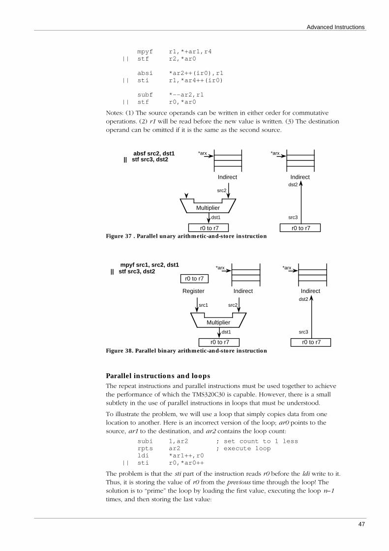
Advanced Instructions
47
mpyf r1,*+ar1,r4|| stf r2,*ar0
absi *ar2++(ir0),r1|| sti r1,*ar4++(ir0)
subf *--ar2,r1|| stf r0,*ar0
Notes: (1) The source operands can be written in either order for commutativeoperations. (2) r1 will be read before the new value is written. (3) The destinationoperand can be omitted if it is the same as the second source.
src2
r0 to r7
dst1
Indirect
*arx
Multiplier
absf src2, dst1|| stf src3, dst2
Indirect
*arx
r0 to r7
src3
dst2
Figure 37 . Parallel unary arithmetic-and-store instruction
src2
r0 to r7
dst1
IndirectRegister
src1
*arx
Multiplier
mpyf src1, src2, dst1|| stf src3, dst2
r0 to r7
Indirect
*arx
r0 to r7
src3
dst2
Figure 38. Parallel binary arithmetic-and-store instruction
Parallel instructions and loopsThe repeat instructions and parallel instructions must be used together to achievethe performance of which the TMS320C30 is capable. However, there is a smallsubtlety in the use of parallel instructions in loops that must be understood.
To illustrate the problem, we will use a loop that simply copies data from onelocation to another. Here is an incorrect version of the loop; ar0 points to thesource, ar1 to the destination, and ar2 contains the loop count:
subi 1,ar2 ; set count to 1 lessrpts ar2 ; execute loopldi *ar1++,r0
|| sti r0,*ar0++
The problem is that the sti part of the instruction reads r0 before the ldi write to it.Thus, it is storing the value of r0 from the previous time through the loop! Thesolution is to “prime” the loop by loading the first value, executing the loop n–1times, and then storing the last value:

Realtime DSP: The TMS320C30 Course
48
subi 2,ar2 ; set count to 2 lessldi *ar1++,r0 ; prime looprpts ar2 ; execute loopldi *ar1++,r0
|| sti r0,*ar0++sti r0,*ar0++ ; clean up loop
Note well that the loop counter has two subtracted from it before the loop, insteadof just one. This means that, if this loop occurs in a situation in which the loopcount might be one, then this case must be tested for. (To see why, suppose thatar2 contained 1. Subtracting two gives 231–1, since ar2 is treated as an unsignednumber. The loop will then execute 232 times—not what was intended!)
Auxiliary register updates in parallel instructionsI have so far skipped a small point but important point about the use of parallelinstructions. All have two indirect operands, which can be incremented ordecremented by zero, one, ir0, or ir1. For example, the code
fix *ar0++,r0|| sti r0,*ar1++
could appear in a loop that converts an array of floats to integers. But in this case,the increment is on two different pointers—the integer array is in a differentlocation to the float array. But suppose that we wanted to write the converted databack to its original location: then both parts of the above instruction then use thesame auxiliary register, so where should we put the increment operator (++)?
In all parallel instructions, if both indirect operands use the same auxiliary register,the correct addresses for both will be generated, but only one of them updates it.In this particular case, the desired instruction is:
fix *ar0,r0|| sti r0,*ar0++
Note that the assembler will give a warning that both indirect operands use thesame auxiliary register.
If spare registers are available, you could also do this:
ldi ar0,ar1....fix *ar0++,r0
|| sti r0,*ar1++
The operand that updates the auxiliary register (if both are the same) is:
• For parallel arithmetic-and-store, and load-and-store
The destination operand of the store. The above instruction is an example ofthis.
• For parallel load and parallel store
The second indirect operand. For example,ldi *+ar0,r1
|| ldi *ar0++(ir0),r0
which loads two consecutive locations into r0 and r1 , and increments theauxiliary register.
• For parallel multiply-and-add/subtract
The second indirect operand, where the mpyf/i part is “before” the addf/i orsubf/i part. For example,
mpyf *ar0,*ar0++,r1|| addf r0,r1,r2

Advanced Instructions
49
which squares the pointed-to location and increments the pointer, as well asadding two registers.


51
Special Addressing Modes
The TMS320C30 has—in common with other modern DSP devices—two specialaddressing modes: circular addressing, and bit-reversed addressing. Theseaddressing modes significantly increase device performance for a number ofcommon signal processing algorithms.
Circular addressing
OverviewCircular addressing can be used in a surprising number of algorithms: convolutionand correlation, input/output buffers, inter-process communication, Viterbidecoding, and column-wise matrix addressing.
Consider an FIR filter, as illustrated in Figure 39:
ys(n) = ∑i = 0
k–1coeffs(k–i–1) xs(n – i)
xs
N
× coeffs
xs N–k–1N
k–10
ys N
n
× coeffs
xs N+q–k–1N+q
k–10
ys N+q
N+qn
Figure 39. FIR filtering
The implementation of an FIR filter is often visualised as a shift register: each newinput sample is shifted into one end of the buffer, and the oldest sample discardedfrom the other end.
In software, however, the data is stored in an array of memory, rather than in ashift register. One way to implement the shift register is to actually shift all datavalues down through an array:
for each input sample x dotemp1 = x;for i = k-1 downto 0 do
temp2 = buf[i];buf[i] = temp1;temp1 = temp2;
Figure 40 illustrates this process.
Earlier DSP devices, such as the TMS32010, had a special instruction that combinedthis data shift with a multiply-accumulate instruction (for implementing filters).

Realtime DSP: The TMS320C30 Course
52
Modern devices, however, provided a more general means of achieving the sameend:
curpos = 0;for each input sample x do
buf[curpos++] = x;if (curpos >= k) then
curpos = 0;
Thus, each new input sample is just written into the next location in memory;when the end is reached; the index into the array “wraps” back to zero. It is thiswrap-around of the array index (actually implemented as a pointer wrap-around)that is done for free by the circular addressing hardware of the TMS320C30).Figure 41 illustrates this process.
xN–k+1
xN–k+2
xN–2
xN–1
xNn=N x
N+1
xN–k+2
xN–1
xNn=N+1 x
N+1x
N–k+3x
N+2
xN–k+3
xNn=N+2 x
N+1x
N–k+4x
N+2x
N+3
Time Buffer contents Next sample
Figure 40 Implementing a shift register (1)
Time Buffer contents Next sample
xN–k+1
xN–k+2
xN–2
xN–1
xNn=N x
N+1
n=N+1 xN–k+3
xN+2
xN–k+2
xN–2
xN–1
xN
xN+1
n=N+2 xN–k+4
xN+3
xN–k+3
xN–2
xN–1
xN
xN+1
xN+2
Figure 41. Implementing a shift register (2)
TMS320C30 implementationTo implement a circularly-addressed array of length N in TMS320C30 assembler,you need:
1. A block of memory, starting on a multiple of
2log 2 N( )+1[ ] , if N is a power of 2
2ceil log 2 N( )[ ] , otherwise
For example, a circularly-addressed array of 25 elements must start on amultiple of 32. An array of 64 elements must start on a multiple of 128.7
7 This is a trap for the unwary: if the block size is a power of two, then it must start atan address that is aligned at twice its size.

Special Addressing Modes
53
2. An auxiliary register, which is initialised to point to somewhere within thearray.
3. The block size register, bk, which must be initialised to the size of the array.
Supposing that the C variable circbuf contains the address of a suitable piece ofmemory for the array. TMS320C30 assembler to write (integer) input values intothis array would be:
ldi @_circbuf,ar4 ; ar4 is circular pointerloop:
call _readval ; get input sample in r0ldi 25,bk ; array has 25 elements8
sti r0,*ar4++% ; write and circular modifyb loop
Note that the “%” following the post-increment “++” indicates that the auxiliaryregister modification is to take place in circular fashion. Post-decrement addressingcan also be used, and register can be modified by a value between 0 and 255, orby either of the index registers. Thus, the following instruction is valid:
addi *ar4++(3)%,*ar5--(ir0)%,r2
(As it stands, of course, the above code is useless, since the input data is neverprocessed! This is only an example to illustrate the addressing mode.)
Bit-reversed addressing
OverviewThe common forms of the radix-2 FFT algorithm either requires its input data in“scrambled” order, or produces its output data in scrambled order. Figure 42depicts the decimation-in-time FFT with scrambled output data.
8 bk is loaded each time through the loop because the call to _readval may corrupt itotherwise. If _readval is an assembler routine know not to corrupt bk, then bk can beloaded once before the loop.

Realtime DSP: The TMS320C30 Course
54
x(0)
x(1)
x(2)
x(3)
x(4)
x(5)
x(6)
x(7)
x(8)
x(9)
x(10)
x(11)
x(12)
x(13)
x(14)
x(16)
X(0)
X(8)
X(4)
X(12)
X(2)
X(10)
X(6)
X(14)
X(1)
X(9)
X(5)
X(13)
X(3)
X(11)
X(7)
X(15)
W016
W016
W416
W416
W216
W216
W616
W616
W016
W416
W216
W616
W116
W516
W316
W716
W016
W016
W016
W016
W416
W416
W416
W416
–1
–1
–1
–1
–1
–1
–1
–1
–1
–1
–1
–1
–1
–1
–1
–1
–1
–1
–1
–1
–1
–1
–1
–1
–1
–1
–1
–1
–1
–1
–1
–1
W016
W016
W016
W016
W016
W016
W016
W016
Figure 42. Decimation-in-time FFT Butterfly Diagram
The ordering of the output data is commonly referred to as “bit-reversed” order,because the indexes into the output array can be obtained by reversing the orderof bits in each index. Thus, data items 0, 1, 2, 3 etc, are stored in locations 0, 8, 4,12, and so on. Re-ordering the data array typically consumes as much as 30% ofthe total FFT time on a conventional processor.
Because the FFT is a very commonly-used signal processing algorithm—both inactuality and as a benchmark for comparing the performance of DSP devices—most DSP devices provide a special “bit-reversed addressing” mode just forimplementing the data re-ordering.
TMS320C30 implementationTo implement bit-reversed addressing on an array of length N=2n in TMS320C30assembler, you need:
1. A block of memory, starting on a multiple of N. Thus, bit-reversed addressingoperates only with power-of-2 sized arrays.
2. An auxiliary register, which is initialised to point to the start of the array.
3. Index register 0, ir0, which must be initialised to half the size of the array.
The bit-reversed addressing mode is indicated by a “b” following the post-increment “++” symbol, as shown in the following code fragment from a bit-reversed data copying routine:
rptb loop;
ldf *ar0++(ir0)b,r0 ; load real, store imaginary|| stf r1,*+ar1;loop: ldf *+ar0,r1 ; load next imag, store real|| stf r0,*ar1++(ir1)

Special Addressing Modes
55
Note that bit-reversed addressing operates only with ir0, and only in post-increment mode. For more information on bit-reversed addressing, see Chapters 5and 11 of the TMS320C3x User’s Guide.
Allocating memory arraysBoth the circular and bit-reversed addressing modes require that memory beallocated on power-of-2 boundaries in memory. There are a number of ways to dothis:
• Use the linker to locate specially-named memory sections at a pre-determinedlocation.
• Use the linker’s .align directive to specify that a certain memory area belocated on the appropriate boundary.
• Cast a C pointer to a hard-wired address. For example, the C declarationfloat *buffer = (float *)0x809800;
will create a C pointer called buffer, pointing to the start of internal memory.
• Create buffers at the correct location using an appropriate dynamic memoryallocator.
The last option is the most flexible. The Texas Instruments C Compiler is nowprovided with a suitable allocation routine, balloc(), with which you can specifythe alignment of the block to be allocated.
The DSPKit libraries contain a faster and more flexible set of routines for memoryallocation—see the DSPMem documenation of DSPKit. As a simple example oftheir use, the code to create a circular buffer of 25 elements within theTMS320C30’s on-chip memory will include the following code:
main(){
float *buffer0;float *buffer;
processor_init(); /* initialise system */buffer0 = mem_alloc( 25, FastHeap ); /* get memory */buffer = buffer0;
/* use buffer, which is on a 32-word boundary */
mem_free( buffer0, 25, FastHeap ); /* free mem */}


57
On-chip Peripherals
The TMS320C30 contains several on-chip peripherals: two serial ports, twoprogrammable timers, and a DMA (direct memory access) controller. This chapterintroduces these peripherals and describes how they can be programmed in C. Fordetailed information on the peripherals, however, you will need to refer to chapter8 of the TMS320C3x User’s Guide.
Overview of peripheralsThe peripherals are controlled by a number of on-chip registers, located from808000H to 80807FH in the TMS320C30’s address space (although addresses up to809BFFH are reserved as peripheral address space). These registers can be readand written just like any other memory location. Each peripheral circuit has itsown block of memory, as shown in Figure 43.
808000H
808010H
808020H
808030H
808040H
808050H
808060H
808070H
DMA Controller
Timer 0
Timer 1
Unused
Serial Port 0
Serial Port 1
Bus Control
Unused
Figure 43. Peripheral Memory Map
In this chapter, we will look only at the timers—the other peripherals are morecomplex, and are described in more detail in following chapters.
The timersEach timer control block in fact only contains three registers, as shown in Figure44. The “global control” register contains mode select fields and status flags. Thecounter register contains the current timer count; it is incremented at half the clockrate: if the clock rate is 30 MHz, for example (as it is in the EVM board), the countregister will be incremented at 15 MHz. The period register contains the timerperiod; a timer interrupt is generated and the timer counter reset to zero when thevalue in the counter register reaches the value in the period register.
See pages 8-2 to 8-11 of the TMS320C3x User’s Guide for information on theoperation of the timer control bits.

Realtime DSP: The TMS320C30 Course
58
Global control
Reserved
Reserved
Reserved
Counter
Reserved
Reserved
Reserved
Period
Reserved
Reserved
Reserved
Reserved
Reserved
Reserved
Reserved
Timer 0 Timer 1
808020H 808030H
808021H 808031H
808022H 808032H
808023H 808033H
808024H 808034H
808025H 808035H
808026H 808036H
808027H 808037H
808028H 808038H
808029H 808039H
80802AH 80803AH
80802BH 80803BH
80802CH 80803CH
80802DH 80803DH
80802EH 80803EH
80802FH 80803FH
Figure 44. Timer control block
Accessing hardware memory locations in CThere are a number of ways in which the timer registers can be accessed from C.Suppose we wish to write a variable, say timer_period, into the period register ofTimer 1. Here is one way:
*(unsigned int *)0x808038 = timer_period;
This C statement creates a pointer to the timer register (which is, after all, just amemory location as far as the code is concerned), and uses the pointer to write tothe register.
This method is both error-prone and difficult to read; it is easy to inadvertentlytype say 0x808083h as the address, for example. One could use macros to definememory locations; for example,
#define TIMER_1_PERIOD (*(unsigned int *)0x808038)...TIMER_1_PERIOD = timer_period;
However, you end up defining a lot of macros! A (better, I think) method is todefine a C structure that mimics the memory layout of the timer control block. Inthe DSPKit file periph.h, for example, you will find the following structuredefinition:

Peripherals
59
typedef struct{
timer_control_t control;unsigned rsv1[3];
unsigned counter;unsigned rsv2[3];
unsigned period;unsigned rsv3[7];
} timer_t;
(timer_control_t is defined elsewhere in that file.)
Now we can access the timers as follows:
#define TIMER0 ((timer_t *)0x808020)#define TIMER1 ((timer_t *)0x808030)
...TIMER0->period = timer_period;
This can be taken a step further: we can define a single C structure to mimic thewhole peripheral memory space! In periph.h, you can find the following structuredefinition:
typedef struct{
dma_t dma; /* DMA controller */unsigned rsv1[16];timer_t timers[2]; /* Two timers */port_t ports[2]; /* Two serial ports */bus_t bus; /* Bus control */unsigned rsv2[16];
} peripherals_t;
If you compare this structure with Figure 43, you will see the correspondenceimmediately. In order to access the peripheral memory space, the file periph.cactually defines a pointer to this memory (rather than just using a constant pointeras before):9
volatile peripherals_t*peripherals_p = (volatile peripherals_t *)0x808000;
periph.h also defines this macro:
#define peripherals (*peripherals_p)
The period register of timer 1 is thus accessed by
peripherals.timers[1].period = timer_period;
Using the definitions in the file periph.h, you can read or write any peripheralregister in this way.
9 The volatile keyword is used to prevent the optimiser from breaking your code.Suppose you were polling a flag in the peripheral address space, testing for whether ithad been set yet. The optimiser would see this code as a good opportunity to removeunneeded code, and would load the flag in question into a register once, before theloop! As far as the optimiser can tell, the location you are repeatedly testing neverchanges, so there is no need to load it each time through the loop. The volatilekeyword informs the compiler that the variable you are examining in fact can bechanged by some external agent (a peripheral circuit, in this case), so it must be readafresh each time through the loop.

Realtime DSP: The TMS320C30 Course
60
Accessing structure- and bit-fieldsThe previous section showed how to access whole registers in the peripheralmemory space. However, many registers contain a large number of bit-fields. Forexample, Figure 45 shows the structure of one of the timer “global control”registers.
TSTAT INV CLKSRC C/P HLD GO xx xx DATINDATOUT I/O FUNC
Bit 12—31 11 10 9 8 7 6 5 4 3 2 1 0
XXXXXXXXXXXX
Figure 45. Bit-fields in the timer global control register
Suppose we wished to set bit 6 (the GO bit), without changing any other bits. Inassembler, we have to load the word from memory, set the bit, and write the wordback again. For example,
ldp 808030hldi @808030h,r0or 40h,r0sti r0,@808030h
We could mimic this in C if we wanted:
temp = peripherals.timers[1].control;temp |= 0x40;peripherals.timers[1].control = temp;
However, C also allows you to define bit-fields in structures—that is, structureelements that are only a given number of bits in size. To illustrate, periph.h definesthe timer_control_t structure as follows:
typedef struct{
unsigned func : 1 ;unsigned io : 1 ;unsigned datout : 1 ;unsigned datin : 1 ;unsigned unused1 : 2 ;unsigned go : 1 ;unsigned hld : 1 ;unsigned cp : 1 ;unsigned clksrc : 1 ;unsigned inv : 1 ;unsigned tstat : 1 ;unsigned rsv1 : 4 ;unsigned rsv2 : 16;
} timer_control_t;
If you compare this with Figure 45, you will see how the elements of this structurematch the bit fields contained in the timer control register.10 Now, the go bit canbe set by:
peripherals.timers[1].control.go = 1;Clearly, any of the bits in any peripheral control register can be read or written thisway. To close this chapter, the following code fragment initialises and starts timer1:
10 Note: The relative order of the declarations in timer_control_t and the control bits iscompletely machine-dependent.

Peripherals
61
/* * Set all bits of control register to zero. */*(unsigned *)&peripherals.timers[1].control = 0;
/* * Set the period register and control bits */peripherals.timers[1].period = timer_period;
peripherals.timers[1].control.clksrc = 1; /* internal clk */peripherals.timers[1].control.hld = 1; /* release */peripherals.timers[1].control.func = 1; /* TCLK is o/p */peripherals.timers[1].control.go = 1; /* start */


63
Interrupts
Interrupts are used to allow a processor to respond to external events; in theTMS320C30 environment, these events can include a timer time-out, data beingreceived or transmitted by a serial port, completion of a DMA transfer, or acommand or data from a controlling host computer.
This chapter describes the TMS320C30 interrupt structure, and how to set up anduse interrupts using first the ints module of the DSPKit library, and then assemblercode.
This chapter is still incomplete—contact the author for the current version.
C30 interrupt structure
Interrupt sourcesThe TMS320C30 has twelve hardware interrupt sources, including a hardwarereset. The names of these interrupts defined by the DSPKit library are:
Reset
Device reset interrupt. This occurs when the TMS320C30 ispowered up. When you start running a program in theTMS320C30 Source Debugger, the program executes as though ahardware reset had occurred.
External0, External1, External2, and External3
External interrupt sources. These are triggered by four pins of theTMS320C30, and are used for communication with the hostcomputer in the EVM board. In other systems, the use of theseinterrupts is determined by the design of the external circuitry.
Transmit0, Receive0
Serial port 0 interrupts. these interrupts are triggered when serialport 0 has finished transmitting a word or has received a word.
Transmit1, Receive1
Serial port 1 interrupts.
Timer0, Timer1
Timer interrupts. Each of the on-board timers can generate aninterrupt when it times out.
DMA
DMA (direct memory access) controller interrupt. This is triggeredby completion of a DMA transfer.
Interrupt vectorsThe first twelve locations of memory are occupied by the hardware interruptvectors. These location contain the address of an interrupt service routine (ISR),which is to process the corresponding interrupt when it occurs. In the TMS320C3xUser's Guide, these locations are shown as in Figure 46:

Realtime DSP: The TMS320C30 Course
64
00h
01h
02h
03h
04h
05h
06h
07h
08h
09h
0Ah
00Bh
RESET
INT0
INT1
INT2
INT3
XINT0
RINT0
XINT1
RINT1
TINT0
TINT1
DINT
Figure 46. TMS320C30 Interrupt Vectors
(Note that the names of these interrupts defined by DSPKit are different to thenames in the User's Guide.)
Interrupts and polling
Basic interrupt operationInterrupts occur asynchronously of the program being executed by the CPU—inother words, they can occur at any time. Let us suppose that the CPU is currentlyperforming some task, such as (say) calculating the power spectrum of a portionof a signal. While it is doing so, another input sample from the A/D converterarrives at serial port 0 (which we assume is connected to the converter).
Since serial port 0 has just received a data word, it triggers the Receive0 interrupt.Assuming that interrupts are currently enabled, the TMS320C30 performs thefollowing:
1. It disables any further interrupts.
Although we haven’t come to it yet, the GIE bit in the status register, ST, iscleared.
2. It pushes the current program counter plus one onto the stack.
For example, suppose that the TMS320C30 is executing the ldi instruction inthe following code fragment:
addi *ar0++,r0 ; address 0158Hldi *ar1,r1 ; address 0159Hmpyi r0,r1,r2 ; address 015AH
The address 015A (hexadecimal) is loaded onto the stack.
3. It loads the value from the corresponding interrupt vector into the programcounter.
In this case, it loads the word at memory address 06H into the programcounter, so that execution continues from that address. Since the location 06Hshould contain the address of the interrupt service routine (ISR) for receiveinterrupt 0, this ISR will now be executed.
4. The ISR must terminate with a reti instruction, instead of a rets instruction. Thisinstruction pops the top of the stack into the program counter, and sets theGIE bit.
In our example, the CPU will continue executing from the mpyi instruction, asthough nothing had ever happened between the ldi and the mpyi instructions

Interrupts
65
Characteristics of interrupt service routines.As you can see, calling an ISR is very similar to calling a normal subroutine. Thereare two key differences:
• An ISR must preserve every register, including the status register (ST). Thisensures that the main program functions correctly even though an ISR can beexecuted between any two instructions. You will recall that normalsubroutines only need to preserve certain registers (see C-AssemblerInterfacing).
• An ISR must end with a reti instruction, so that interrupts are re-enabled afterthe ISR completes.
PollingPolling is an alternative method of responding to external events, which is simplerto program than interrupts, and can sometimes even be more efficient. Withinterrupts, the CPU executes its main program without regard for external events;the external events force the CPU to respond to them by interrupting it. Withpolling, however, the CPU must “poll” for external events.
In the case of the data received on serial port 0, the CPU will repeatedly test a bitin the serial port control registers11 to check whether a word has been received. Ifit has, the CPU takes appropriate action. If it has not, the CPU either doessomething useful for a short while, or just waits a short while (perhaps as little asone instruction) before trying again.
A silly analogy may help understand the difference. (Acting out the followingscenarios might help appreciate the analogy!)
Suppose I decided that one of my students has to make me coffee periodically inorder to pass this course. Using an interrupt-driven protocol, the student wouldinterrupt me when the coffee was ready; I would handle the interrupt by takingthe coffee and drinking it. The sequence of events looks like this:
Me Student
“Make me a cup of coffee!”
Starts making coffee
(Busy working) (Busy making coffee)
(Some time passes....)
“Your coffee is ready”
Stops working, and takes coffeefrom student.
Hands me coffee
Drinks coffee, and then goes backto work
Sits around waiting for nextcommand.
11 Or the interrupt flag (if) register.

Realtime DSP: The TMS320C30 Course
66
Using a polling protocol, however, I would periodically ask the student whetherthe coffee was ready yet. Finally, it would be, and I would then be able to drink it.The sequence of events looks like this:
Me Student
“Make me a cup of coffee!”
Starts making coffee
(Does a little work) (Busy making coffee)
“Is the coffee ready yet?” “No”
(Does a little work) (Busy making coffee)
“Is the coffee ready yet?” “No”
(Does a little work) (Busy making coffee)
“Is the coffee ready yet?” “Yes”
Stops working, and takes coffeefrom student.
Hands me coffee
Drinks coffee, and goes back towork
Sits around waiting for nextcommand.
Accessing and controlling interrupts in CTo simplify the use of interrupts, DSPKit provides a utility module called ints,which contains a number of C-callable routines.
Initialising interruptsThe code sequence below will ensure that all interrupts are reset and all interruptsvectors cleared. It is contained in the default DSPKit system initialisation routine,processor_init(). If your program does not start by calling processor_init(), itshould execute the following sequence early on.
disable_interrupts();clear_pending_interrupts();disable_all_interrupts();reset_isrs();

Interrupts
67
Installing and removing interruptsInterrupt service routines are easily installed at run-time, as illustrated by thefollowing code fragment from the DSPKit library evmlib, which installs an ISR forone of the serial ports.12
/* * Install the data ISR and abort if error */if ( ! install_isr( Receive0, c_int50 ) ){
fatal( "AIC interrupt installation error" );}
When closing down a peripheral such as a serial port, the corresponding ISRshould be removed. For example,
uninstall_isr( Receive0 );
Coding interrupt service routinesInterrupt service routines can be coded in C, simply by giving the ISR function aname of the format c_intxx, where xx is a number in the range 00 to 99. Forexample, the ISR used in the above examples starts as follows:
static voidc_int50( void ){
integer item;
/* * Read from serial port, convert to 14-bit integer. */item = (peripherals.ports[MYPORT].receive << 16) >> 18;...
}
12 In fact, this is a simplified version of the code.


69
Memory Management
A typical TMS320C30 system has several regions of memory, of varying sizes andspeeds. Of course, all have at least the on-chip memory, which is capable of up tothree accesses per instruction cycle. Most will have some form of externalmemory—perhaps fast zero-wait-state static RAM, or maybe an external programROM. More expensive systems may also have much larger memory built withdynamic RAMs, with one or two wait states. In multi-processor systems, there mayalso be shared memory accessible by more than one processor.
Effective use and management of these different memory areas—especially theprecious internal memory—is crucial, and this chapter describes how memory canbe allocated and used effectively. Detailed discussion of the ins and outs of whyinternal memory is so precious is left until Chapter 12.
This chapter is incomplete: contact the author for the current version.

70
Pipeline Conflicts
To achieve peak performance from the TMS320C30, it is necessary to understandhow the device’s instruction pipeline works and how instruction ordering andmemory usage interact with the pipeline.
This chapter is not yet complete—contact the author for the current version.