received : july 16, 2015 received: 16,
TRANSCRIPT

STATE OF UTAHDEPARTMENT OF NATURAL RESOURCES
DIVISION OF OIL, GAS AND MINING
APPLICATION FOR PERMIT TO DRILL 1. WELL NAME and NUMBER
Coleman #1-29-29
2. TYPE OF WORK
DRILL NEW WELL REENTER P&A WELL DEEPEN WELL 3. FIELD OR WILDCAT
WILDCAT
4. TYPE OF WELLOil Well Coalbed Methane Well: NO
5. UNIT or COMMUNITIZATION AGREEMENT NAME
6. NAME OF OPERATORSOLI DEO GLORIA PETROLEUM, LLC
7. OPERATOR PHONE818 679-1339
8. ADDRESS OF OPERATOR11309 Ocean Road, Frisco, TX, 75035
9. OPERATOR [email protected]
10. MINERAL LEASE NUMBER(FEDERAL, INDIAN, OR STATE)
N/A
11. MINERAL OWNERSHIP
FEDERAL INDIAN STATE FEE 12. SURFACE OWNERSHIP
FEDERAL INDIAN STATE FEE
13. NAME OF SURFACE OWNER (if box 12 = 'fee')Coleman Brothers, Ltd.
14. SURFACE OWNER PHONE (if box 12 = 'fee')435-6548526
15. ADDRESS OF SURFACE OWNER (if box 12 = 'fee')148 W. Center St., ,
16. SURFACE OWNER E-MAIL (if box 12 = 'fee')
17. INDIAN ALLOTTEE OR TRIBE NAME(if box 12 = 'INDIAN')
18. INTEND TO COMMINGLE PRODUCTION FROMMULTIPLE FORMATIONS
YES (Submit Commingling Application) NO
19. SLANT
VERTICAL DIRECTIONAL HORIZONTAL
20. LOCATION OF WELL FOOTAGES QTR-QTR SECTION TOWNSHIP RANGE MERIDIAN
LOCATION AT SURFACE 2390 FNL 1322 FEL SWNE 29 2.0 S 9.0 W U
Top of Uppermost Producing Zone 2390 FNL 1322 FEL SWNE 29 2.0 S 9.0 W U
At Total Depth 2390 FNL 1322 FEL SWNE 29 2.0 S 9.0 W U
21. COUNTYWASATCH
22. DISTANCE TO NEAREST LEASE LINE (Feet)11600
23. NUMBER OF ACRES IN DRILLING UNIT40
25. DISTANCE TO NEAREST WELL IN SAME POOL(Applied For Drilling or Completed)
13739
26. PROPOSED DEPTHMD: 11000 TVD: 11000
27. ELEVATION - GROUND LEVEL
7493
28. BOND NUMBER
pending
29. SOURCE OF DRILLING WATER /WATER RIGHTS APPROVAL NUMBER IF APPLICABLE
to be determined
Hole, Casing, and Cement Information
String Hole Size Casing Size Length Weight Grade & Thread Max Mud Wt. Cement Sacks Yield Weight
Cond 24 20 0 - 60 54.0 Unknown 8.3 Class A 46 1.18 15.6
Surf 12.25 9.625 0 - 3000 36.0 J-55 ST&C 9.0 Premium Lite High Strength 750 2.19 12.0
Class G 200 1.15 15.8
Prod 8.75 5.5 0 - 11000 23.0 N-80 LT&C 10.6 Class G 970 1.15 15.8
Class G 690 1.15 15.8
ATTACHMENTS
VERIFY THE FOLLOWING ARE ATTACHED IN ACCORDANCE WITH THE UTAH OIL AND GAS CONSERVATION GENERAL RULES
WELL PLAT OR MAP PREPARED BY LICENSED SURVEYOR OR ENGINEER COMPLETE DRILLING PLAN
AFFIDAVIT OF STATUS OF SURFACE OWNER AGREEMENT (IF FEE SURFACE) FORM 5. IF OPERATOR IS OTHER THAN THE LEASE OWNER
DIRECTIONAL SURVEY PLAN (IF DIRECTIONALLY OR HORIZONTALLY DRILLED) TOPOGRAPHICAL MAP
NAME William Braden TITLE Agent PHONE 303 969-9610
SIGNATURE DATE 07/23/2013 EMAIL [email protected]
API NUMBER ASSIGNED 43051500010000 APPROVAL
FORM 3
AMENDED REPORT
Received: July 16, 2015
CONFIDE
NTIAL
Returned Unapproved
FORM 3STATE OF UTAH
DEPARTMENTOF NATURALRESOURCES AMENDEDREPORTDIVISION OF OIL, GAS AND MINING
APPLICATION FOR PERMIT TO DRILL 1. WELL NAME and NCUM Rn#1-29-29
2. TYPE OF WORK 3. FIELD OR WILDCATDRILLNEWWELL REENTERP&AWELL DEEPENWELLI WLDCAT
4. TYPE OF WELL 5. UNIT or COMMUNITIZATION AGREEMENT NAMEOil Well Coalbed Methane Well: NO
6. NAME OF OPERATOR 7. OPERATOR PHONESOLI DEO GLORIA PETROLEUM, LLC 818 679-1339
8. ADDRESS OF OPERATOR 9. OPERATOR E-MAIL11309 Ocean Road, Frisco, TX, 75035 [email protected]
10. MINERAL LEASE NUMBER 11. MINERAL OWNERSHIP 12. SURFACE OWNERSHIP(FEDERAL,INDIAN,ORSTATEN/A FEDERAL INDIANISTATE FEE FEDERAL INDIAN STATE FEEI
13. NAME OF SURFACE OWNER (if box 12 = 'fee') 14. SURFACE OWNER PHONE (if box 12 = 'fee')Coleman Brothers, Ltd. 435-6548526
15. ADDRESS OF SURFACE OWNER (if box 12 = 'fee') 16. SURFACE OWNER E-MAIL (if box 12 = 'fee')148 W. Center St., ,
17. INDIAN ALLOTTEE OR TRIBE NAME 18. INTEND TO COMMINGLE PRODUCTION FROM 19. SLANT
(if box 12 = 'INDIAN')MULTIPLE FORMATIONS
YES (Submit Commingling Application) NO VERTICAL DIRECTIONAL HORIZONTAL
20. LOCATION OF WELL FOOTAGES QTR-QTR SECTION TOWNSHIP RANGE MERIDIAN
LOCATION AT SURFACE 2390 FNL 1322 FEL SWNE 29 2.0 S 9.0 W U
Top of Uppermost Producing Zone 2390 FNL 1322 FEL SWNE 29 2.0 S 9.0 W U
At Total Depth 2390 FNL 1322 FEL SWNE 29 2.0 S 9.0 W U
21. COUNTY 22. DISTANCE TO NEAREST LEASE LINE (Feet) 23. NUMBER OF ACRES IN DRILLING UNITWASATCH 11600 40
25. DISTANCE TO NEAREST WELL IN SAME POOL 26. PROPOSED DEPTH(Applied For Drilling or Completed) MD: 11000 TVD: 11000
13739
27. ELEVATION - GROUND LEVEL 28. BOND NUMBER 29. SOURCE OF DRILLING WATERIWATER RIGHTS APPROVAL NUMBER IF APPLICABLE
7493 pending to be determined
Hole, Casing, and Cement Information
Hole Size Casing Size Length Weight Grade & Thread Max Mud Wt. Cement Sacks Yield Weight
24 20 0 - 60 54.0 Unknown 8.3 Class A 46 1.18 15.6
12.25 9.625 0 - 3000 36.0 J-55 ST&C 9.0 Premium Lite High Strength 750 2.19 12.0
Class G 200 1.15 15.8
8.75 5.5 0 - 11000 23.0 N-80 LT&C 10.6 Class G 970 1.15 15.8
Class G 690 1.15 15.8
ATTACHMENTS
VERIFY THE FOLLOWING ARE ATTACHED IN ACCORDANCE WITH THE UTAH OIL AND GAS CONSERVATION GENERAL RULES
WELL PLATOR MAP PREPARED BY LICENSED SURVEYOR OR ENGINEER COMPLETE DRILLING PLAN
AFFIDAVIT OF STATUS OF SURFACE OWNER AGREEMENT(IF FEE SURFACE) FORM 5. IF OPERATOR IS OTHER THAN THE LEASE OWNER
DIRECTIONAL SURVEY PLAN (IF DIRECTIONALLYOR HORIZONTALLY DRILLED) TOPOGRAPHICAL MAP
NAME William Braden TITLE Agent PHONE 303 969-9610
SIGNATURE DATE 07/23/2013 EMAIL [email protected]
API NUMBER ASSIGNED 43051500010000 APPROVAL
Received: July 16,

DRILLING PROGNOSIS SOLI DEO GLORIA PETROLEUM, LLC
Coleman #1-29-29 SWNE Section 29, Township 2S-Range 9W
Wasatch County, Utah
July 11, 2013 GENERAL NOTE: This well is to be drilled as a tight hole. Unauthorized personnel are not to be allowed on the rig floor, and all information is to be kept confidential. Surface Location: 2,390’ FNL and 1,322' FEL (SWNE), Section 29, T2S-R9W Latitude: 40.278433° N and Longitude: 110.920481° W (NAD 83) Proposed TD: 11,000’ (TVD), 11,000’ (MD) Wasatch Elevation: 7,490 ' GL (graded); 7,507' KB (estimated). Drilling Rig: To be determined MECHANICAL Casing Design: SIZE INTERVAL LENGTH DESCRIPTION SFt SFc SFb 20” 0’ - 60’ 60’ Conductor (0.250” WT) -- -- -- 9-5/8” 0’ - 3,000’ 3,000’ 36#, J-55, STC 3.92 1.44 1.17 5-1/2” 0’ - 11,000’ 11,000’ 23#, N-80, LTC 1.98 1.84 1.63 2-7/8” 0' - 11,000' 11,000’ 6.5#, N-80, EUE NOTE: It is intended to set surface casing at 3,000’. If mud weight exceeds 10.6 ppg at TD, or if salts are
encountered then the casing design may be altered. Tack weld guide shoe to surface casing. Strap weld first casing joint and the bottom of the collar of the second joint. Clean and drift all strings of casing prior to running. Remove all thread sealant (Kindex) prior to running. Unload production casing and tubing strings with a forklift.
Received: July 23, 2013
CONFIDE
NTIAL
Returned Unapproved
DRILLING PROGNOSISSOLI DEO GLORIA PETROLEUM, LLC
Coleman #1-29-29SWNE Section 29, Township 2S-Range 9W
Wasatch County, Utah
July 11, 2013
GENERAL
NOTE: This well is to be drilled as a tight hole. Unauthorized personnel are not to be allowed on the rigfloor, and all information is to be kept confidential.
Surface Location: 2,390' FNL and 1,322' FEL (SWNE), Section 29, T2S-R9WLatitude: 40.278433° N and Longitude: 110.920481° W (NAD 83)
Proposed TD: 11,000' (TVD), l1,000' (MD) Wasatch
Elevation: 7,490 ' GL (graded);7,507' KB (estimated).
Drilling Rig: To be determined
MECHANICAL
Casing Design:
SIZE INTERVAL LENGTH DESCRIPTION SFt SFc SFb
20" 0' - 60' 60' Conductor (0.250"WT) -- -- --
9-5/8" 0' - 3,000' 3,000' 36#, J-55, STC 3.92 1.44 1.175-1/2" 0' - 11,000' 11,000' 23#, N-80, LTC 1.98 1.84 1.632-7/8" 0' - 11,000' 11,000' 6.5#, N-80, EUE
NOTE: It is intended to set surface casing at 3,000'. If mud weight exceeds 10.6 ppg at TD, or if salts areencountered then the casing design may be altered. Tack weld guide shoe to surface casing. Strapweld first casing joint and the bottom of the collar of the second joint. Clean and drift all stringsof casing prior to running. Remove all thread sealant (Kindex) prior to running. Unloadproduction casing and tubing strings with a forklift.
Received: July 23,

Drilling Prognosis Coleman #1-29-29 Page 2 CEMENT CASING/HOLE SIZE CEMENT SLURRY SX PPG YIELD 20” - 24” Cement to surface with 6 yds Redi-mix. 9-5/8" - 12-1/4" Baker Premium Lite Cement + 3% CaCl2 + 1/4 pps flocele 750 12.00 2.19
Class 'G' Cement + 1% CaCl2 + 1/4 pps flocele 200 15.8 1.15
NOTE: Precede cement with 50 bbl fresh water. Have 100 sx neat cement and one-inch tubing on location for topping-off. Cement volume assumes a 12-1/4" hole and 100% excess although the actual cement volumes will be calculated from the caliper log assuming 25% excess.
5 1/2" – 8-3/4" 1st Stage Class 'G' Cement containing a fluid loss additive and a retarder as required. 970 15.8 1.15 2nd Stage Class 'G' Cement containing a fluid loss additive and a retarder as required. 690 15.8 1.15
NOTE: Cement volume calculated assuming an 8-3/4” hole + 25% excess (TOC at 5,000’). Precede cement with 1000 gal mud flush and 10 bbl fresh water spacer. Cement top contingent upon the presence of potentially productive intervals. Actual cement volume will be determined from the caliper log. Once the float has been tested after pumping Stage 1 open the DV tool and circulate with mud for 4 hours before pumping the Stage 2 cement slurry. Run pilot tests on proposed cement with actual make-up water. Cement design may be altered depending on actual bottomhole temperatures and the presence of any lost circulation. Do not move the casing (under any circumstances) while setting the casing slips. After landing casing on bottom, water back mud until viscosity of +40 seconds (funnel viscosity) is achieved.
CEMENTING ACCESSORIES Surface Casing: 1) Guide shoe with insert float located one joint above shoe. 2) Top wiper plug (rubber). 3) Centralizer with stop ring in middle of shoe joint.
4) Centralizers over collars on first five connections, omitting float collar. 5) Two centralizers on top two joints of surface casing.
6) Use a total of eight centralizers. Production Casing: 1) Differential-fill float collar located one joint above differential-fill float shoe. 2) Top and bottom wiper plug. 3) Centralizer with stop-ring in the middle of shoe joint. 4) Centralize through and 100' on either side of potentially productive intervals. 5) DV tool set at apx. 7,500' with a centralizer in the middle of the three joints
above and below it. 6) Thread-lock all connections through float collar and use API casing dope on all
remaining connections.
Received: July 23, 2013
CONFIDE
NTIAL
Returned Unapproved
Drilling PrognosisColeman #1-29-29Page 2
CEMENT
CASING/HOLE SIZE CEMENT SLURRY SX PPG YIELD
20" - 24" Cement to surface with 6 yds Redi-mix.
9-5/8" - 12-1/4" Baker Premium Lite Cement+ 3% CaCl2+ 1/4 pps flocele 750 12.00 2.19
Class 'G' Cement+ 1% CaCl2+ 1/4 pps flocele 200 15.8 1.15
NOTE: Precede cement with 50 bbl fresh water. Have 100 sx neat cement and one-inch tubingon location for topping-off. Cement volume assumes a 12-1/4" hole and 100% excess althoughthe actual cement volumes will be calculated from the caliper log assuming 25% excess.
5 1/2" - 8-3/4" 1"*StageClass 'G' Cement containing a fluid lossadditive and a retarder as required. 970 15.8 1.15
2nd StageClass 'G' Cement containing a fluid lossadditive and a retarder as required. 690 15.8 1.15
NOTE: Cement volume calculated assuming an 8-3/4" hole + 25% excess (TOC at 5,000').Precede cement with 1000 gal mud flush and 10 bbl fresh water spacer. Cement top contingentupon the presence of potentially productive intervals. Actual cement volume will be determinedfrom the caliper log. Once the float has been tested after pumping Stage 1 open the DV tool andcirculate with mud for 4 hours before pumping the Stage 2 cement slurry. Run pilot tests onproposed cement with actual make-up water. Cement design may be altered depending on actualbottomhole temperatures and the presence of any lost circulation. Do not move the casing (underany circumstances) while setting the casing slips. After landing casing on bottom, water back muduntil viscosity of±40 seconds (funnel viscosity) is achieved.
CEMENTING ACCESSORIES
Surface Casing: 1) Guide shoe with insert float located one joint above shoe.2) Top wiper plug (rubber).3) Centralizer with stop ring in middle of shoe joint.4) Centralizers over collars on first five connections, omitting float collar.5) Two centralizers on top two jointsof surface casing.6) Use a total of eight centralizers.
Production Casing: 1) Differential-fill float collar located one joint above differential-fill floatshoe.2) Top and bottom wiper plug.3) Centralizer with stop-ring in the middle of shoe joint.4) Centralize through and 100' on either side of potentially productive intervals.5) DV tool set at apx. 7,500' with a centralizer in the middle of the three joints
above and below it.6) Thread-lock all connections through float collar and use API casing dope on all
remaining connections.
Received: July 23,

Drilling Prognosis Coleman #1-29-29 Page 3 WELLHEAD Casing Head: 9-5/8" x 11” x 5,000 psi WP slip on welded casing head with two-2" LP outlets.
Outlets equipped with one-2" 5,000 psi WP gate valve, and one-2" x 5,000 psi WP blind flange on the outlets.
Tubing Head: 11" x 7-1/16" x 5,000 psi WP tubing head with two - 2" x 5,000 psi flanged outlets.
Outlets to be equipped with 2" x 5,000 psi WP gate valves. Upper Half: To be determined. MUD PROGRAM INTERVAL WEIGHT (PPG) VISCOSITY (SEC) WL (CCS) 0' – 3,000' 8.5 - 9.0 ppg 30 - 45 sec NC Spud well with fresh water. Circulate reserve pit to maintain clear water at the pump suction. Addition of lime and/or a selective flocculant may be made at the flowline to promote solids settling in the reserve pit. Keep hole full and drill pipe moving at all times. Sweep hole with gel/lime/polymer as necessary, and prior to running surface casing. INTERVAL WEIGHT (PPG) VISCOSITY (SEC) WL (CCS) 3,000' – 5,000' 9.0 – 9.4 ppg 28 - 34 sec NC Drill out from surface casing with water. After drilling five feet of new formation, perform FIT to 12.5 ppg equivalent. Circulate reserve pit to maintain clear water at the pump suction. Addition of lime and/or a selective flocculant may be made at the flowline to promote solids settling in the reserve pit. Keep hole full and drill pipe moving at all times. Sweep hole with gel/lime/polymer as necessary and prior to running casing. INTERVAL WEIGHT (PPG) VISCOSITY (SEC) WL (CCS) 5,000' – 11,000' 9.4 – 10.6 ppg 35 - 50 sec 8-10 ccs At 5,000’ mud-up with low-solids, non-dispersed mud system utilizing gel, caustic soda, and PHPA polymer. Keep trip speeds down to reduce surge-swab pressure. Keep hole full at all times. Monitor pit volume constantly as lost circulation and water flows should be expected at all times. Will need to add lost circulation material from the top of the Lower Green River formation at 5,170' to TD. The mud weight should increase due to over-pressuring to 10.0 ppg by 5,170 and up to 10.6 ppg by TD. Check for flow after all drilling breaks. Sweep hole as dictated by hole conditions. Keep the drill pipe moving at all times. Monitor the system for the presence of bacteria and treat out accordingly. Fluid loss may be reduced with the addition of PAC material. DEVIATION In order to keep the deviations to a minimum a straight-hole or steerable mud motor will be used to drill the surface hole and to drill out from under the surface pipe for as long as is deemed necessary. The dog-leg severity should be kept under 1.0o per 100' for the entire hole if possible.
Received: July 23, 2013
CONFIDE
NTIAL
Returned Unapproved
Drilling PrognosisColeman #1-29-29Page 3
WELLHEAD
Casing Head: 9-5/8" x 11" x 5,000 psi WP slip on welded casing head with two-2" LP outlets.Outlets equipped with one-2" 5,000 psi WP gate valve, and one-2" x 5,000 psi WPblind flange on the outlets.
Tubing Head: 11" x 7-1/16" x 5,000 psi WP tubing head with two - 2" x 5,000 psi flanged outlets.Outlets to be equipped with 2" x 5,000 psi WP gate valves.
Upper Half: To be determined.
MUD PROGRAM
INTERVAL WEIGHT (PPG) VISCOSITY (SEC) WL (CCS)
0' - 3,000' 8.5 - 9.0 ppg 30 - 45 sec NC
Spud well with fresh water. Circulate reserve pit to maintain clear water at the pump suction. Addition oflime and/or a selective flocculant may be made at the flowline to promote solids settling in the reserve pit.Keep hole full and drill pipe moving at all times. Sweep hole with gel/lime/polymer as necessary, and priorto running surface casing.
INTERVAL WEIGHT (PPG) VISCOSITY (SEC) WL (CCS)
3,000' - 5,000' 9.0 - 9.4 ppg 28 - 34 sec NC
Drill out from surface casing with water. After drilling five feet of new formation, perform FIT to 12.5 ppgequivalent. Circulate reserve pit to maintain clear water at the pump suction. Addition of lime and/or aselective flocculant may be made at the flowline to promote solids settling in the reserve pit. Keep hole fulland drill pipe moving at all times. Sweep hole with gel/lime/polymer as necessary and prior to runningcasing.
INTERVAL WEIGHT (PPG) VISCOSITY (SEC) WL (CCS)
5,000' - 11,000' 9.4 - 10.6 ppg 35 - 50 sec 8-10 ccs
At 5,000' mud-up with low-solids, non-dispersed mud system utilizing gel, caustic soda, and PHPApolymer. Keep trip speeds down to reduce surge-swab pressure. Keep hole full at all times. Monitor pitvolume constantly as lost circulation and water flows should be expected at all times. Will need to add lostcirculation material from the top of the Lower Green River formation at 5,170' to TD. The mud weightshould increase due to over-pressuring to 10.0 ppg by 5,170 and up to 10.6 ppg by TD. Check for flowafter all drilling breaks. Sweep hole as dictated by hole conditions. Keep the drill pipe moving at all times.Monitor the system for the presence of bacteria and treat out accordingly. Fluid loss may be reduced withthe addition of PAC material.
DEVIATION
In order to keep the deviations to a minimum a straight-hole or steerable mud motor will be used to drill thesurface hole and to drill out from under the surface pipe for as long as is deemed necessary. The dog-legseverity should be kept under 1.0° per 100' for the entire hole if possible.
Received: July 23,

Drilling Prognosis Coleman #1-29-29 Page 4 WELL CONTROL EQUIPMENT INTERVAL EQUIPMENT 0’ – 3,000’ None 3,000’ – 11,000’ 11" x 5,000 psi WP double-gate BOP with blind and 4-1/2" pipe and 11" x 5,000 psi
annular rams. Rig should be equipped with upper and lower kelly cocks, as well as stabbing valve (have wrench available at all times). BOP equipment will be tested after nipple-up and every 30 days thereafter. (Notify a Utah Oil and Gas Division field representative (801) 538-5338 prior to testing). Close pipe rams daily and blind rams on trips, recording results on tour sheets.
GEOLOGICAL Geologist: Geologist (Clifton Kees, 214-383-3595) will be on location to look at the Green River
and Wasatch samples. Notify prior to spud and after setting surface casing. Mud Logger: We will use a 2-man mud logging unit from 60’ to TD.
Electric Logging: A DIL-SFL-SP-GR, Litho Density-CNL-GR-CAL-Micro and a BCS-GR-CAL to be
run from TD to the base of surface casing. Run a FMI-Fracture Detection Microscanner-Stratigraphic Dipmeter and a Dual Burst Thermal Decay Time log from TD to the base of surface casing if necessary. Schlumberger will be the logging company if possible.
Formation Tops: Assumes KB elevation of 7,507 ft.
FORMATION TOP (TVD) SUB SURFACE Lower Green River 5,170' +2,337'
Wasatch 9,590' -2,083' Total Depth 11,000' -3,493'
Drillstem Testing: Potential test of any significant show (possible test of the Lower Green River or
Wasatch). Unless otherwise indicated, recommended DST times will be as follows: IF (15 min.), ISI (60 min), FF (60-90 min, depending on blow at surface), and FSI (2 x FF). Keep length of anchor to a minimum while testing. Test string should include dual packers, top and bottom pressure recorders, jars, safety joint, sample chamber, and reverse circulating sub (pressure and bar-activated). Monitor fluid entry throughout test with echometer.
MISCELLENEOUS 1. It is important that this well's deviation is kept to a minimum and that the dog-leg severity is kept
under 1.0o from 60' to TD. It is intended to use a straight-hole motor or a steerable system with MWD capabilities (directional contractor to be determined).
2. Pump carbide lag prior to running surface casing and prior to drilling out shoe. Pump efficiencies will be calculated from this information. Run frequent carbide lags while drilling to determine degree of hole washout. 3. Monitor mud hydraulics closely. An in-gauge hole is extremely critical to achieve open-hole packer seats, interpretable logs, and a good cement bond. 4. The source of water in unknown at this time.
Received: July 23, 2013
CONFIDE
NTIAL
Returned Unapproved
Drilling PrognosisColeman #1-29-29Page 4
WELL CONTROL EQUIPMENT
INTERVAL EQUIPMENT
0' - 3,000' None
3,000' - 11,000' 11" x 5,000 psi WP double-gate BOP with blind and 4-1/2" pipe and 11" x 5,000 psiannular rams. Rig should be equipped with upper and lower kelly cocks, as well asstabbing valve (have wrench available at all times). BOP equipment will be testedafter nipple-up and every 30 days thereafter. (Notify a Utah Oil and Gas Divisionfield representative (801) 538-5338 prior to testing). Close pipe rams daily and blindrams on trips, recording results on tour sheets.
GEOLOGICAL
Geologist: Geologist (Clifton Kees, 214-383-3595) will be on location to look at the Green Riverand Wasatch samples. Notify prior to spud and after setting surface casing.
Mud Logger: We will use a 2-man mud logging unit from 60' to TD.
Electric Logging: A DIL-SFL-SP-GR, Litho Density-CNL-GR-CAL-Micro and a BCS-GR-CAL to berun from TD to the base of surface casing. Run a FMI-Fracture DetectionMicroscanner-Stratigraphic Dipmeter and a Dual Burst Thermal Decay Time log fromTD to the base of surface casing if necessary. Schlumberger will be the loggingcompany if possible.
Formation Tops: Assumes KB elevation of 7,507 ft.
FORMATION TOP (TVD) SUB SURFACELower Green River 5,170' +2,337'
Wasatch 9,590' -2,083'
Total Depth 11,000' -3,493'
Drillstem Testing: Potential test of any significant show (possible test of the Lower Green River orWasatch). Unless otherwise indicated, recommended DST times will be as follows:IF (15 min.), ISI (60 min), FF (60-90 min, depending on blow at surface), and FSI(2 x FF). Keep length of anchor to a minimum while testing. Test string shouldinclude dual packers, top and bottom pressure recorders, jars, safety joint, samplechamber, and reverse circulating sub (pressure and bar-activated). Monitor fluidentry throughout test with echometer.
MISCELLENEOUS
1. It is important that this well's deviation is kept to a minimum and that the dog-leg severity is keptunder 1.0° from 60' to TD. It is intended to use a straight-hole motor or a steerable system with MWDcapabilities (directional contractor to be determined).
2. Pump carbide lag prior to running surface casing and prior to drilling out shoe. Pump efficiencieswill be calculated from this information. Run frequent carbide lags while drilling to determine degreeof hole washout.
3. Monitor mud hydraulics closely. An in-gauge hole is extremely critical to achieve open-hole packerseats, interpretable logs, and a good cement bond.
4. The source of water in unknown at this time.
Received: July 23,

Drilling Prognosis Coleman #1-29-29 Page 5 5. Notify Utah Oil and Gas Division prior to spud, and 24-hrs prior to BOP test. 6. Reserve pit is to be lined with a 12-mil synthetic liner. 7. In general, the above prognosis is presented as a guideline only; and is subject to change as dictated by hole conditions and geological interpretation. PERSONNEL OFFICE CELL Dan Hall, Consulting Engineer 303-969-9610 303-618-1877 David Braden, Consulting Engineer 303-969-9610 303-902-6340 Clifton Kees, Consulting Geologist 214-383-3595 940-447-1969 SURFACE OWNER ADDRESS PHONE Coleman Bros., Ltd., 148 W. Center St. a Utah Limited Liability Company Heber, UT 84032 Ranch Manager – Steve Ellis (435) 654-8526
Prepared by: _____________________________________ Dan Hall Energy Operating Company, Inc.
Received: July 23, 2013
CONFIDE
NTIAL
Returned Unapproved
Drilling PrognosisColeman #1-29-29Page 5
5. Notify Utah Oil and Gas Division prior to spud, and 24-hrs prior to BOP test.
6. Reserve pit is to be lined with a 12-mil synthetic liner.
7. In general, the above prognosis is presented as a guideline only; and is subject to change as dictatedby hole conditions and geological interpretation.
PERSONNEL OFFICE CELL
Dan Hall, Consulting Engineer 303-969-9610 303-618-1877David Braden, Consulting Engineer 303-969-9610 303-902-6340Clifton Kees, Consulting Geologist 214-383-3595 940-447-1969
SURFACE OWNER ADDRESS PHONE
Coleman Bros., Ltd., 148 W. Center St.a Utah Limited Liability Company Heber, UT 84032
Ranch Manager - Steve Ellis (435) 654-8526
Prepared by:
Dan HallEnergy Operating Company, Inc.
Received: July 23,

ROBERT L.KAY
No. 161319
A
Received: July 23, 2013
CONFIDE
NTIAL
Returned Unapproved
T2S, R9 W, U. S. B. &M. PIONEER OIL & GASWell location, COLEMAN #1-29-29, located asshown in the SW 1/4 NE 1/4 of Section 29, T2S,R9W, U.S.B.&M., Wasatch County, Utah.
Set Marked Set forkedst°"
NB9'5J'26"W - 5278.78' (Meas.) "°"' BASIS OF ELEVATIONI SPOT ELEVATIONAT THE SOUTH 1/4 CORNER OF SECTION 28,
T2S, R9W, U.S.B.&M. FROM THE RASPBERRY KNOLLSQUADRANGLE,UTAH, 7.5 MINUTE QUAD. (TOPOGRAPHIC MAP)PUBLISHED BY THE UNITED STATES DEPARTMENTOF THEINTERIOR, GEOLOGICALSURVEY. SAID ELEVATIONIS MARKEDAS BEING 7271 FEET.
^g BASIS OF BEARINGSN - N - BASIS OF BEARINGS IS A G.P.S. OBSERVATION.I
COLEMAN †-29-29E/ev. Ungraded Ground = 749J'
o - oo o o
SCALE
CERTIFICATEo LAND
THIS IS TO CERTIFYTHAT THE ABOVE DFIELD NOTES OF ACTUALSURVEYS M OR UNDESUPERVISIONAND THAT THE SAME U IgBEST OF MY KNOWLEDGEAND BELIE O
UINTAH ENGINEERING & LAND SURVEYINGN89°57'W- 5276.04' (G.L.O.) seg y
stone 85 SOUTH 200 EAST - VERNAL, UTAH 84078
(435) 789-1017LEGEND: SCALE DATE SURVEYED: DATE DRAWN:
NAD 83(2011)(EPOCH:201o.oooo) 1" = 1000' 02-12-13 02-18-13=
90° SYMBOL (SURFACE LOCATION)LATITUDE =
40°16'42.36" (40.278433) FARTi' REFERENCES= PROPOSED WELL HEAD. LONGITUDE=
110°55'13.73" (110.920481) B.H. C.A. S.S. G.L.O. PLATNAD 27 (SURFACE LOCATION) WEATHER FILE
A = SECTION CORNERS LOCATED. LATITUDE =40°16 42.53" (40.278481) PIONEER OIL & GASLONGITUDE=
110°55'11.14" (110.919761) COLD
Received: July 23,

Received: July 23, 2013
CONFIDE
NTIAL
Returned Unapproved
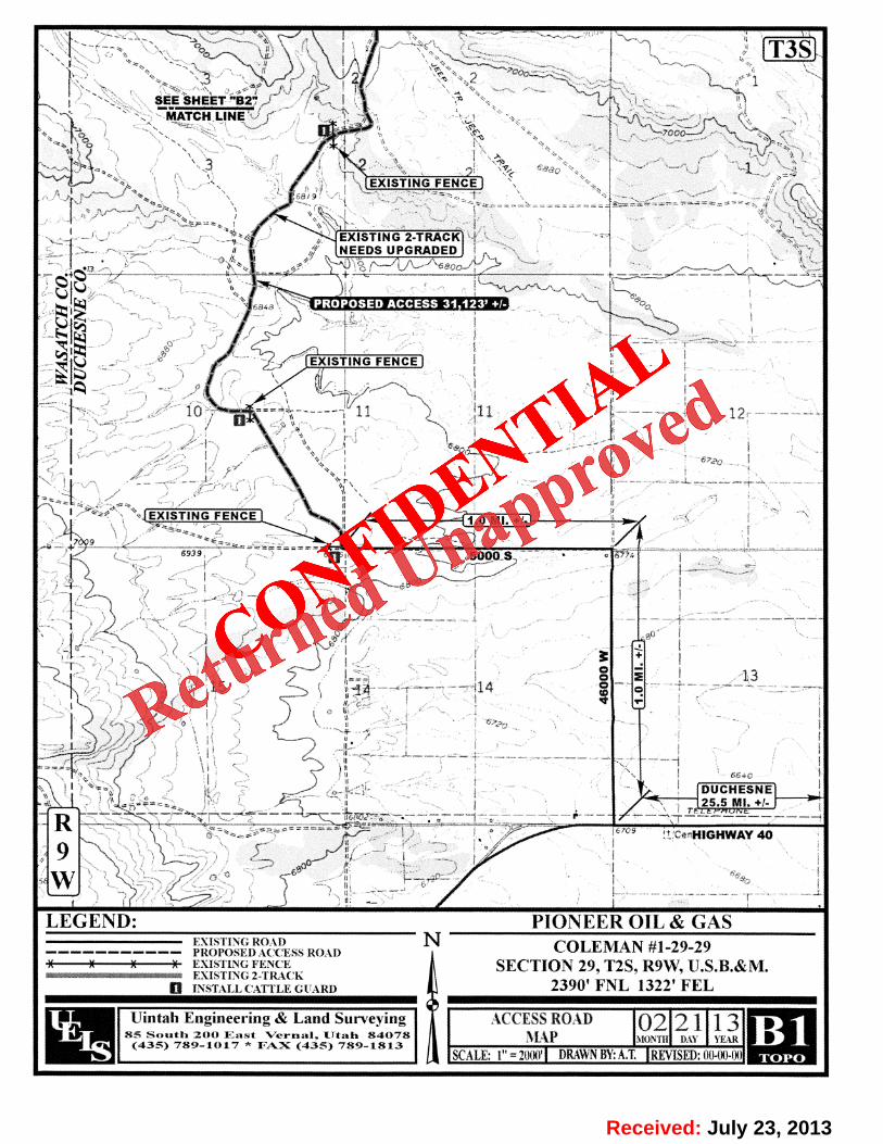
PIONEER OIL & GASCOLEMAN #1-29-29
SECTION 29, 2S, R9W, U.S.B.&M.
PROCEED IN A WESTERLY DIRECTION FROM DUCHESNE, UTAH ALONG U.S.HIGHWAY 40 APPROXIMATELY 25.5 MILES TO THE JUNCTION OF THIS ROAD AND46000 W TO THE NORTH; TURN RIGHT AND PROCEED IN A NORTHERLYDIRECTION APPROXIMATELY 1.0 MILE TO THE JUNCTION OF THIS ROAD AND 5000S TO THE WEST; TURN LEFT AND PROCEED IN A WESTERLY DIRECTIONAPPROXIMATELY l.0 MILE TO THE BEGINNING OF THE PROPOSED ACCESS ROADTO THE NORTH; FOLLOW ROAD FLAGS IN A NORTHERLY, THENNORTHWESTERLY; THEN NORTHEASTERLY, THEN NORTHWESTERLY, THENWESTERLY, THEN SOUTHWESTERLY, THEN NORTHWESTERLY DIRECTIONAPPROXIMATELY 31,123' TO THE PROPOSED LOCATION.
TOTAL DISTANCE FROM DUCHESNE, UTAH TO THE PROPOSED WELL LOCATIONIS APPROXIMATELY 33.4 MILES.
Received: July 23,

Received: July 23, 2013
CONFIDE
NTIAL
Returned Unapproved
9 8
PROPOSED LOCATIONCOI E IAN #1 2 9
SEE TOPO "81' & "B2"
T3S
LEGEND: PIONEER OIL & GASPROPOSED LOCATION N COLEMAN #1-29-29
SECTION 29, T2S, R9W, U.S.R.&M.
-2390' FNL 1322' FEL
Uintah Engineering & Land Surveying HT'ESS RO U) 0 2 1 1385 South 200 East Verunl, IJtah 84078 N.$ DAY YFAR(435) 789-1017 * EAX (435) 789-1813SCALE:1:100,000 DBAWNBY:LI REVISED:0(MXMl0
Received: July 23,
Received: July 23, 2013
CONFIDE
NTIAL
Returned Unapproved
\T3S' i
SEE 'SHEET "B2"ATON LINE rk
' 3 1 'EXISTING FENCE
EXISTING 2-TRACKNEEDSUPGRADED
EXISTING FENCE
10 ---- '11 11 12
JEXISTING FENCE 1.0 Mt.+/-
5000 S *
o -
o E 1314 e
i DUCHESNEb,
n25.5 1911.+/-
R ce HIGHWAY 40
9
LEGEND: PIONEER OIL & GASEXISTING ROAo N COLEMAN #1-29-29
----------- PROPOSED ACCESS ROAD:t :: EXISTING FENCE SECTION 29, T2S, R9W, U.S.R.&M.mammewmmmmmmrmam EXISTING 2-TILtCK
INSTALL CATTLE GUARD 2390' FNL 1322' FEL
Uintah Engineering & Land Surveying ACCESS ROAD 02 21 13- 85 South 200 East Vernal, IJtah 84078 MÀŸ TH ILW YEAR(435) 789-1017 * FAX (435) 789-1813
SCALE:l"=2¾ DRAWNBY:A.T.REVISED:0MKMW
Received: July 23,

Received: July 23, 2013
CONFIDE
NTIAL
Returned Unapproved
Ro
PROPOSED LOCATION:COLEMAN #1-29-29
EXISTING 2-TRACKNEEDS UPGRADED
EXISTING FENCE
ras
R'86
T3S EXISTING FENCE
EXISTING FENCE
MATCH LINESEE SHEET "Bi"
LEGEND: PIONEER OIL & GASEXISTING ROAD N COLEMAN #1-29-29
----------- PROPOSED ACCESS ROA1: EXISTINGFENCE SECTION 29, T2S, R9W, ILS.B.&M.
mummmmmmanneman EXISTING 2-TRACKB INSTALL CATTLE GUARDS 2390' FNL 1322' FEL
Uintah Engineering & Land Surveying ACCESSROAD 02 2 1 13 e85 South 200 East Vernal, Utah 84078 jÃl) MON11 DAY YEAR
(435) 789-1017 * FAX (435) 789-1813SCALE:1"= 2m DRAWNBY:A.T. REVISED:(RMXM)0
Received: July 23,

Received: July 23, 2013
CONFIDE
NTIAL
Returned Unapproved
R9 '
PROPOSED LOCATIONCOLEMAN #1-29-29
T2S
LEGEND: PIONEER OIL & GASp' DISPOSAL WELLs N COLEMAN #1-29-29
PRODUCING WELLS ABANDONED WELLS SECTION 29, T2S, R9W, U.S.B.& M.SHUT IN WELLS -#- TEMPORARILY ABANDONED 2390' FNL 1322' FEL
Uintah Engineering & Land Surveying TOPOGR A PH I C 02 21 13- SS South 200 East Vernal, ITtah 84078 NI Á Ÿ 'H IRY YEAR(435) 789-1017 * FAX (435) 789-1813SCALE:1" = 200(? DRAWNBY:A.T. REVISED:DIMXM)0
Received: July 23,

Received: July 23, 2013
CONFIDE
NTIAL
Returned Unapproved
BEFORE THE UTAH DIVISION OF OIL,
GAS AND MINING
IN THE MATTER OF THE APPLICATION BY SOLIDEO GLORIA PETROLEUM, LLC REGARDING ANAPPLICATION FOR PERMIT TO DRILL THECOLEMAN #1-29-29 WELL LOCATED IN THE SWNEOF SEC. 29, T2S-R9W IN WASATCH COUNTY, UTAH
AFFIDAVTT OF STATUS OF SURFACE OWNER AGREEMENT
STATEOFCOLORADO )) ss.
COUNTY OF JEFFERSON )
Dan Hall, being first duly sworn, deposes and says that he has been in contact with the surface owner
regarding the drilling of the above referenced well and that he feels an amicable surface use agreement will be
successfully negotiated and approved by the surface owner and the operator in the near future.
Dan Hall
Subscribed and sworn to me this 23" day of July, 2013.
Notary PublicJefferson County, ColoradoMy Commission expires:
Received: July 23,
Received: July 23, 2013
CONFIDE
NTIAL
Returned Unapproved
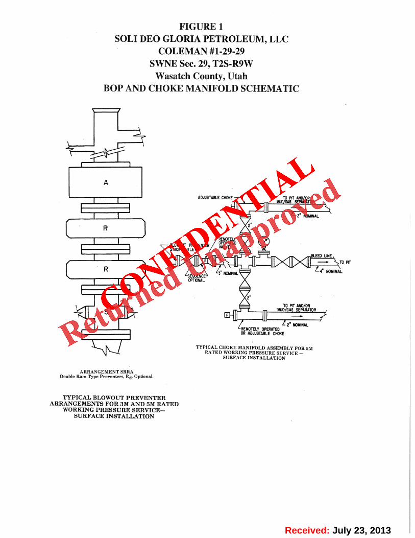
FIGURE 1SOLI DEO GLORIA PETROLEUM, LLC
COLEMAN #1-29-29SWNE Sec. 29, T2S-R9W
Wasatch County, UtahBOP AND CHOKE MANIFOLD SCHEMATIC
A
ADJUSTABLECHOKE TOPIT AND/ORMUD/GASSEPARATOR ,
L2 NOMINAL
REMOTELYOPERATEDBLOWOUTPREVENTER VALVE\ STACKOUTLET
BLEEDUNE,
R L4· NOMINA3" NOMNALEQUENCEOPTIONAL
2"
TOPITANC/08'MUD/GASSEPARATOR ,
2° NOMINALREMOTELYOPERATEDCR ADJUSTABLECHOKE
TYPICAL CHOKE MANIFOLD ASSEMBLY FOR SMRATED WORKING PRESSURE SERVICE -
SURFACE INSTALLATION
ARRANGEMENT SRRADouble Ram Type Preventers, Rd, Optional.
TYPICAL BLOWOUT PREVENTERARRANGEMENTSFOR3MAND5MRATED
WORKING PRESSURE SERVICE-SURFACE INSTALLATION
Received: July 23,

Received: July 23, 2013
CONFIDE
NTIAL
Returned Unapproved
PIONEER OIL & GAS FIGURE #iLOCATION LAYOUT FOR '
,, ,SCALE: 1 = 60COLEMAN#1-29-29 DATE: 02-19--13
SECTION 29, T2S, R9W, U.S.B.&M. DRAWNBY: S.S.
2390' FNL 1322' FEL
ProposedTopsoi/ Stockpile .
/. Access RoadC-14.7
-- E-14.4'
55
El 6.5'
/ Round Corners E/. 489.8'as Nee ed
ROFlare Pit is to belocateo' a min. or too'
CONSTRUCT trom the weilHead
DIVERSIONF7ar E/. 505.5' Cut Fi//
..... 44' Trarwition L
o St¤- 2 00
,
49 J.
/ 500 2'
CONSTRUCTDIVERSION
E ENC 4 4 Sto. O
F I Slope
Elev. Ungraded Ground At Loc. Stoke = 7493.5', UINTAH ENGINEERING & LAND SURVEYINGEIN/SHED GRADE ELEV AT LOC. STAKE = 7490.9 es so. zoo rose · verser. es.»avora * (4ss> vas-rotz
Received: July 23,

Received: July 23, 2013
CONFIDE
NTIAL
Returned Unapproved
PIONEER OIL & GAS FIGURE #2x-section TYPICAL CROSS SECTIONS FORscale INCOLEMAN #1-29-29
g LAND1" = 100 SECTION 29, T2S, R9W, U.S.B.&M.
DATE: 02-19-13 2390' FNL 1322' FEL No. 16131DRAWNBY: S.S. \ gRO E
Sta. 4+00
10' 100' 45' 150'
LOCAT/ON STAKE
Sta. 2+00
10' 00' 45' 150'
's Slope = 1 1/2: 1
Sta. 1+00PreconstructionGrade
155 150'
CUT
Sto. 0+00
NOTE APPROX/MATE ACREAGES
ITopsoil should not be WELLS/TE D/S7URBANCE = ± 5.354 ACRESStrridpepedn
S bstrctSuhreed
Area ACCESS ROAD D/STURBANCE = ±21.361 ACRES / L UANT/TY/NCLUDESTOTAL = ±26.715ACRES 5% FOR COMPACT/ON
EXCESS MATERIAL = 7,770 Cu. Yds.APPROXIMATE YARDAGES Topsoil & Pit Backfill = 5,750 Cu. Yds.
(1/2 Pit Vol.)(6") Topsoll Stripping = 2,830 Cu. Yds.EXCESS UNBALANCE = 2,020 Cu. Yds.Rernaining Location = J1,420 Cu. Yds.(After Interim Rehabilitation)
TOTAL CUT = 34,250 CU. YDS. UINTAH ENGINEERING & LAND SURVEYINGFILL = 26,480 CU. YDS• 85 So. 200 East * Vernal, Utah 84078 * (435) 789-1017
Received: July 23,

Received: July 23, 2013
CONFIDE
NTIAL
Returned Unapproved
PIONEER OIL & GAS FIGURE #3TYPlCAL RIG LAYOUT FOR ,,SCALE: 1 = 60'
COLEMAN #1-29-29 DATE: 02-19-13
SECTION 29, T2S, R9W, U.S.B.&M. DRAwN BY: S.S.
2390' FNL 1322' FEL /
. ProposedAccess Road
Topsoi/ Stockp//e
155'
RO
CONSTRUCT gg;DIVERSION / Cut/Fil/DITCH Fo
oe a mnÎbor too, Transition Linefrom the Weil HeadApprox.
TOP ofCut Slope PtPE RACKS
4DO HOUSE
150'
1G
TOILETOMUD SHED
HOPPER
POWER-- - G)-
e -
'¯ TOOLS
CONSTRUCT --- o °-- FUEL
V RSION -- o -
i i i10' WIDE BENCH
Apepro×.
Backn Fill slopeserv
s stockpe
UINTAH ENGINEERING & LAND SURVEYING85 So. 200 East * Vernal, Utah. 84078 * (485) 789-1017
Received: July 23,

!
32
21
31
30
34
22
19
27
29 28
33
20
Coleman#1-29-294305150001
Map Produced by Diana Mason
F1,700 0 1,700850 Feet
1:16,807
Wells QueryStatus
APD - Aproved Permit
H DRL - Spuded (Drilling Commenced)
4 GIW - Gas Injection
!) GS - Gas Storage
! LOC - New Location
7 OPS - Operation Suspended
ª PA - Plugged Abandoned
* PGW - Producing Gas Well
' POW - Producing Oil Well
¸ SGW - Shut-in Gas Well
· SOW - Shut-in Oil Well
6 TA - Temp. Abandoned
" TW - Test Well
¸ WDW - Water Disposal
¸ WIW - Water Injection Well
=) WSW - Water Supply Well
UnitsSTATUS
ACTIVE
EXPLORATORY
GAS STORAGE
NF PP OIL
NF SECONDARY
PI OIL
PP GAS
PP GEOTHERML
PP OIL
SECONDARY
TERMINATED
TOOELE
SAN JUAN
MILLARD
KANE
JUAB
IRON
EMERY
UINTAH
BOX ELDER
GARFIELD
GRAND
UTAH
WAYNEBEAVER
DUCHESNE
SEVIER
SUMMIT
RICH
WASHINGTON
CARBON
SANPETE
CACHE
PIUTE
DAVIS
WASATCH
WEBER
SALT LAKE
DAGGETT
MORGAN
Location Map
API Number: 4305150001Well Name: Coleman #1-29-29 Township: T02.0S Range: R09.0W Section: 29 Meridian: U
Operator: SOLI DEO GLORIA PETROLEUM, LLC
Map Prepared: 10/17/2013
Received: October 17, 2013
CONFIDE
NTIAL
Returned Unapproved
API Number: 4305150001Well Name: Coleman #1-29-29Township: TO2.0S Range: RO9.0W Section: 29 Meridian: U
Operator: SOLI DEO GLORIA PETROLEUM, LLC
Map Prepared: 10/17/2013
1920 21 Map Produced by Diana Mason
22
Welle Query UnitsStatus STATUS
APD-AprovedPermit ACTivE
DRL-spuded(Drillingcommenced) EXPLORATORY
Giw-Gasinjection GAssTORAGE
GS-Gasstorage NFPPoiL
e Loc-NewLocatio NFsEcoNDARY
. OPS-operationsuspendedPioiL
PA-PluggedAbandonedPPGAs
Pow-ProducingoliweliPPoiL
-0- SGw-shut-inGaswell SEcoNDARY
sow-shut-inoliwei TERMINATED
Cdeman TA Temp Abandoned
30 29025915209001
28
27
sw watersupplywell
sox E'DE"ies
Location Map
suMMIT GG
TooELE
31 32 33 34
00 850 0 1.700Feet
1:16,807
Received: October 17,

In summary, the Division of Wildlife Resources recommends: Sage Grouse Access Road
Avoid all disturbances within 1 mile of sage grouse leks. Avoid disturbance to sage grouse winter, breeding, nesting, and brood rearing habitat by
rerouting the southern portion of the well access road to the northeast as shown on the attached map.
Avoid road construction activities from December 1 to June 30. Minimize road traffic and unauthorized access (gating). Minimize road disturbance by grading the least extent possible and avoiding wetlands
where possible. Where avoidance is not possible:
o Implement time-of-day restrictions when the lek is occupied from 2 hours before sunrise to 2 hours after sunrise and 2 hours before sunset to 2 hours after sunset.
o Minimize road traffic from December 1 through June 30. Well Pad
Avoid all disturbances within 1 mile of sage grouse leks. Avoid well construction and drilling activities from December 1 to June 30. Avoid incidents with reserve pits and sage grouse by netting and fencing the pit and then
closing as soon as drilling is complete. Minimize noise to less than 10 dB by installing mufflers on pumps or using electric
motors. Where avoidance is not possible:
o Implement time-of-day restrictions when the lek is occupied from 2 hours before sunrise to 2 hours after sunrise and 2 hours before sunset to 2 hours after sunset.
o Minimize traffic and construction activities from December 1 through June 30. Crucial Mule Deer Winter Range
Avoid all construction and drilling activities December 1 through April 15.
Received: November 05, 2013
CONFIDE
NTIAL
Returned Unapproved
In summary, the Division of Wildlife Resources recommends:
Sage GrouseAccess Road
• Avoid all disturbances within 1 mile of sage grouse leks.• Avoid disturbance to sage grouse winter, breeding, nesting, and brood rearing habitat by
rerouting the southern portion of the well access road to the northeast as shown on theattached map.
• Avoid road construction activities from December 1 to June 30.• Minimize road traffic and unauthorized access (gating).• Minimize road disturbance by grading the least extent possible and avoiding wetlands
where possible.• Where avoidance is not possible:
o Implement time-of-day restrictions when the lek is occupied from 2 hours beforesunrise to 2 hours after sunrise and 2 hours before sunset to 2 hours after sunset.
o Minimize road traffic from December 1 through June 30.
Well Pad• Avoid all disturbances within 1 mile of sage grouse leks.• Avoid well construction and drilling activities from December 1 to June 30.• Avoid incidents with reserve pits and sage grouse by netting and fencing the pit and then
closing as soon as drilling is complete.• Minimize noise to less than 10 dB by installing mufflers on pumps or using electric
motors.• Where avoidance is not possible:
o Implement time-of-day restrictions when the lek is occupied from 2 hours beforesunrise to 2 hours after sunrise and 2 hours before sunset to 2 hours after sunset.
o Minimize traffic and construction activities from December 1 through June 30.
Crucial Mule Deer Winter Range• Avoid all construction and drilling activities December 1 through April 15.
Received: November 05,

Received: November 05, 2013
CONFIDE
NTIAL
Returned Unapproved
Soli Deo Gloria-Coleman #1-29-29
Bradley Hill <[email protected]> Tue, Nov 5, 2013 at 8:22 AMTo: Diana Mason <[email protected]>
Please attach these files to the application as if they were RDCC comments from DWR.
Brad Hill P.G.O & G Permitting Manager/Petroleum GeologistState of UtahDivision of Oil, Gas, & MiningPhone: (801)538-5315Fax: (801)359-3940email: [email protected]
2 attachments
,----
.
- colemanmap.JPG. 10199K
Coleman #1-29-29 recomendations.pdf26K
Received: November 05,

September 23, 2015
SOLI DEO GLORIA PETROLEUM,LLC11309 Ocean RoadFrisco, TX 75035
Re: Application for Permit to Drill - WASATCH County, Utah
Ladies and Gentlemen:
The Application for Permit to Drill (APD) for the Coleman#1-29-29 well , API 43051500010000 that was submitted July 23,2013 is being returned unapproved. If you plan on drill ing this wellin the future, you must f irst submit a new application.
Should you have any questions regarding this matter, please call meat (801) 538-5312.
Sincerely,
Diana Mason
Environmental Scientist
Enclosure
cc: Bureau of Land Management, Vernal, Utah
State of Utahi DEPARTMENT OF NATURAL RESOURCES
/ MICHAEL R. STYLER
GARY R. HERBERT Executitt Director
oorvrnor Division of Oil, Gas and MiningSPENCER J. COX JOHN R.BAZALieutenant Gottrnor Ditvoon Director
September 23, 2015
SOLI DEO GLORIA PETROLEUM,LLC11309 Ocean RoadFrisco, TX 75035
Re: Application for Permit to Drill - WASATCH County, Utah
Ladies and Gentlemen:
The Application for Permit to Drill (APD) for the Coleman#1-29-29 well, API 43051500010000 that was submitted July 23,2013 is being returned unapproved. If you plan on drilling this wellin the future, you must first submit a new application.
Should you have any questions regarding this matter, please call meat (801) 538-5312.
Sincerely,
Diana MasonEnvironmental Scientist
Enclosurecc: Bureau of Land Management, Vernal, Utah
UTAH
DNR
1594 West IT.:<thTemple. Suite 1011:I. P ¯Eo:: 14521:11.Salt Lake City, UT 84114-SSI:I1
teleph.:ce (Bi:il)538-534i:i•facsimile (Bi:il)359-394i:i. TTY (Bi:il) 533-7458.mns.ogm.urah.gor ost.sas a

Status=0Status=0