recent advances in seismic and wind design of wood ... · 6/15/2015 1 seaoa2015 conference and...
TRANSCRIPT

6/15/2015
1
SEAoA 2015 Conference and Convention
Recent Advances in Seismic and Wind Design of Wood Structures &Historic Preservation Examples
Kelly Cobeen
Wiss Janney Elstner Associates, Inc.
1. NEHRP Seismic Design Tech Brief 10
2. 2015 SDPWS Highlights
3. ASCE 7‐16 Alternative Diaphragm Force Level
4. NEHRP Rigid Wall–Flexible Diaphragm Buildings
5. Rigger’s Loft Historic Preservation
6. Anna Head Alumnae Hall Historic Preservation
Seminar Outline
SEAoA 2015 Conference and Convention –Wood 2
6/15/2015
2
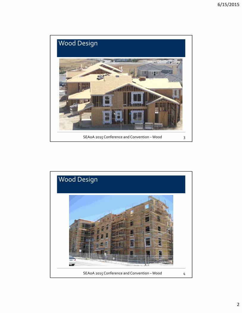
Wood Design
3SEAoA 2015 Conference and Convention –Wood
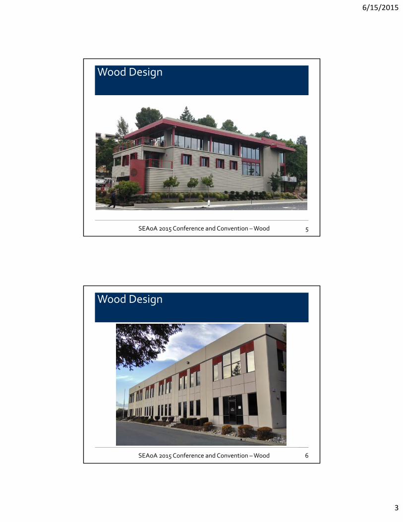
Wood Design
4SEAoA 2015 Conference and Convention –Wood
6/15/2015
3
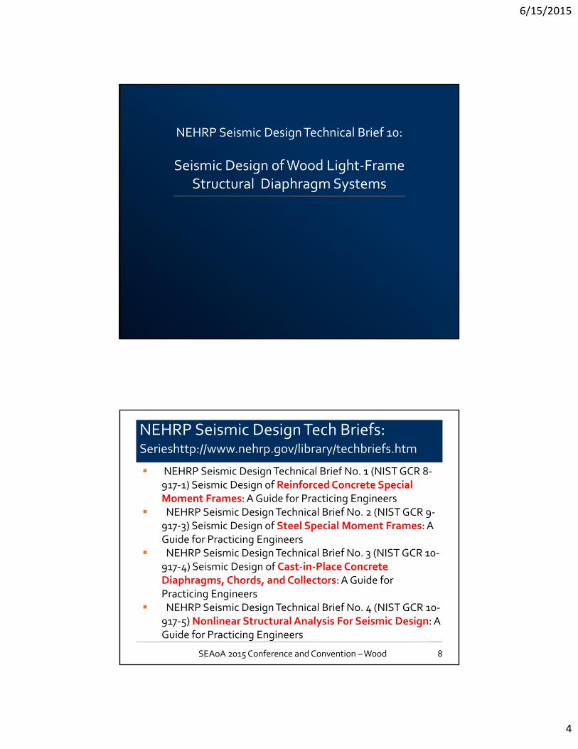
Wood Design
5SEAoA 2015 Conference and Convention –Wood
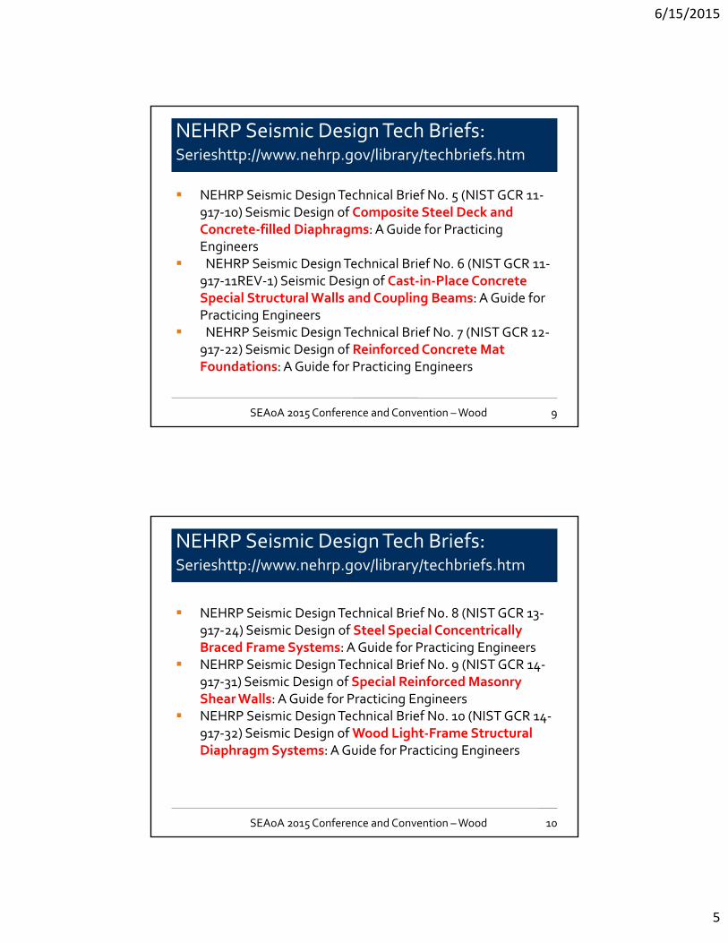
Wood Design
6SEAoA 2015 Conference and Convention –Wood
6/15/2015
4
NEHRP Seismic Design Technical Brief 10:
Seismic Design of Wood Light‐Frame Structural Diaphragm Systems
NEHRP Seismic Design Tech Briefs:Serieshttp://www.nehrp.gov/library/techbriefs.htm
8
NEHRP Seismic Design Technical Brief No. 1 (NIST GCR 8‐917‐1) Seismic Design of Reinforced Concrete Special Moment Frames: A Guide for Practicing Engineers
NEHRP Seismic Design Technical Brief No. 2 (NIST GCR 9‐917‐3) Seismic Design of Steel Special Moment Frames: A Guide for Practicing Engineers
NEHRP Seismic Design Technical Brief No. 3 (NIST GCR 10‐917‐4) Seismic Design of Cast‐in‐Place Concrete Diaphragms, Chords, and Collectors: A Guide for Practicing Engineers
NEHRP Seismic Design Technical Brief No. 4 (NIST GCR 10‐917‐5) Nonlinear Structural Analysis For Seismic Design: A Guide for Practicing Engineers
SEAoA 2015 Conference and Convention –Wood
6/15/2015
5
NEHRP Seismic Design Tech Briefs:Serieshttp://www.nehrp.gov/library/techbriefs.htm
9
NEHRP Seismic Design Technical Brief No. 5 (NIST GCR 11‐917‐10) Seismic Design of Composite Steel Deck and Concrete‐filled Diaphragms: A Guide for Practicing Engineers
NEHRP Seismic Design Technical Brief No. 6 (NIST GCR 11‐917‐11REV‐1) Seismic Design of Cast‐in‐Place Concrete Special Structural Walls and Coupling Beams: A Guide for Practicing Engineers
NEHRP Seismic Design Technical Brief No. 7 (NIST GCR 12‐917‐22) Seismic Design of Reinforced Concrete Mat Foundations: A Guide for Practicing Engineers
SEAoA 2015 Conference and Convention –Wood
NEHRP Seismic Design Tech Briefs:Serieshttp://www.nehrp.gov/library/techbriefs.htm
10
NEHRP Seismic Design Technical Brief No. 8 (NIST GCR 13‐917‐24) Seismic Design of Steel Special Concentrically Braced Frame Systems: A Guide for Practicing Engineers
NEHRP Seismic Design Technical Brief No. 9 (NIST GCR 14‐917‐31) Seismic Design of Special Reinforced Masonry Shear Walls: A Guide for Practicing Engineers
NEHRP Seismic Design Technical Brief No. 10 (NIST GCR 14‐917‐32) Seismic Design of Wood Light‐Frame Structural Diaphragm Systems: A Guide for Practicing Engineers
SEAoA 2015 Conference and Convention –Wood

6/15/2015
6
NEHRP Seismic Design Tech Brief 10:
11SEAoA 2015 Conference and Convention –Wood
Chapter 2: The Roles of Diaphragms
Chapter 3: Diaphragm Components Diaphragm Sheathing Diaphragm Boundary Elements Concrete and Masonry Wall Anchorage and Subdiaphragms
12
NEHRP Seismic Design Tech Brief 10:
SEAoA 2015 Conference and Convention –Wood 12
6/15/2015
7
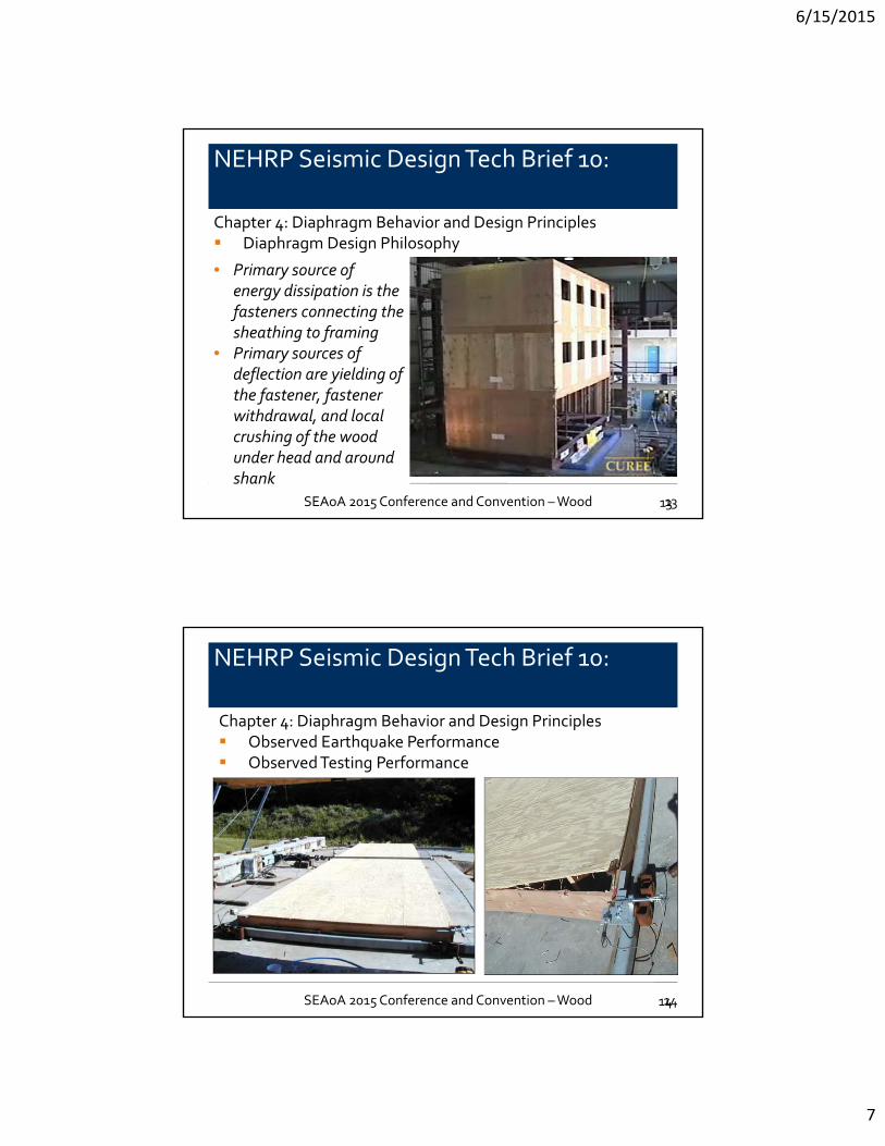
Chapter 4: Diaphragm Behavior and Design Principles Diaphragm Design Philosophy
13
NEHRP Seismic Design Tech Brief 10:
• Primary source of energy dissipation is the fasteners connecting the sheathing to framing
• Primary sources of deflection are yielding of the fastener, fastener withdrawal, and local crushing of the wood under head and around shank
SEAoA 2015 Conference and Convention –Wood 13
Chapter 4: Diaphragm Behavior and Design Principles Observed Earthquake Performance Observed Testing Performance
14
NEHRP Seismic Design Tech Brief 10:
SEAoA 2015 Conference and Convention –Wood 14

6/15/2015
8
Chapter 4: Diaphragm Behavior and Design Principles ASCE 7 – 10 diaphragm classification for purposes of force
distribution to vertical elements Idealized as rigid Calculated as flexible Idealized as flexible Braced with concrete or masonry shear walls, steel braced frames One‐ and two‐family dwellings Wood structural panel diaphragms with up to 1‐1/2” nonstructural topping provided drift limits met at each vertical element
15
NEHRP Seismic Design Tech Brief 10:
SEAoA 2015 Conference and Convention –Wood 15
Chapter 5: Diaphragm Seismic Design Forces Inertial forces generated by the seismic
weight tributary to the diaphragm
Transfer forces generated by discontinued
vertical elements or generated by changes in
stiffness of vertical elements over height of structure
16
NEHRP Seismic Design Tech Brief 10:
SEAoA 2015 Conference and Convention –Wood 16

6/15/2015
9
Chapter 6: Modeling and Analysis Guidance Equivalent Lateral Force Analysis Dynamic Analysis Diaphragm Stiffness Modeling, Deflection Calculations
17
NEHRP Seismic Design Tech Brief 10:
SEAoA 2015 Conference and Convention –Wood 17
Chapter 7: Design GuidanceChapter 8: Detailing and Construction Issues
18
NEHRP Seismic Design Tech Brief 10:
SEAoA 2015 Conference and Convention –Wood 18
6/15/2015
10
2015 SDPWS Design Provisions:
Highlights of Interest
Sec. 4.1.5.1 Anchorage of Concrete and Masonry Walls
Sec. 4.2.5 Horizontal Distribution of Shear
Sec. 4.3.3.4 Shear Walls in a Line & Sec. 4.3.4 Aspect Ratios &Capacity Adjustments
SDPWS Highlights of Interest
20SEAoA 2015 Conference and Convention –Wood
6/15/2015
11
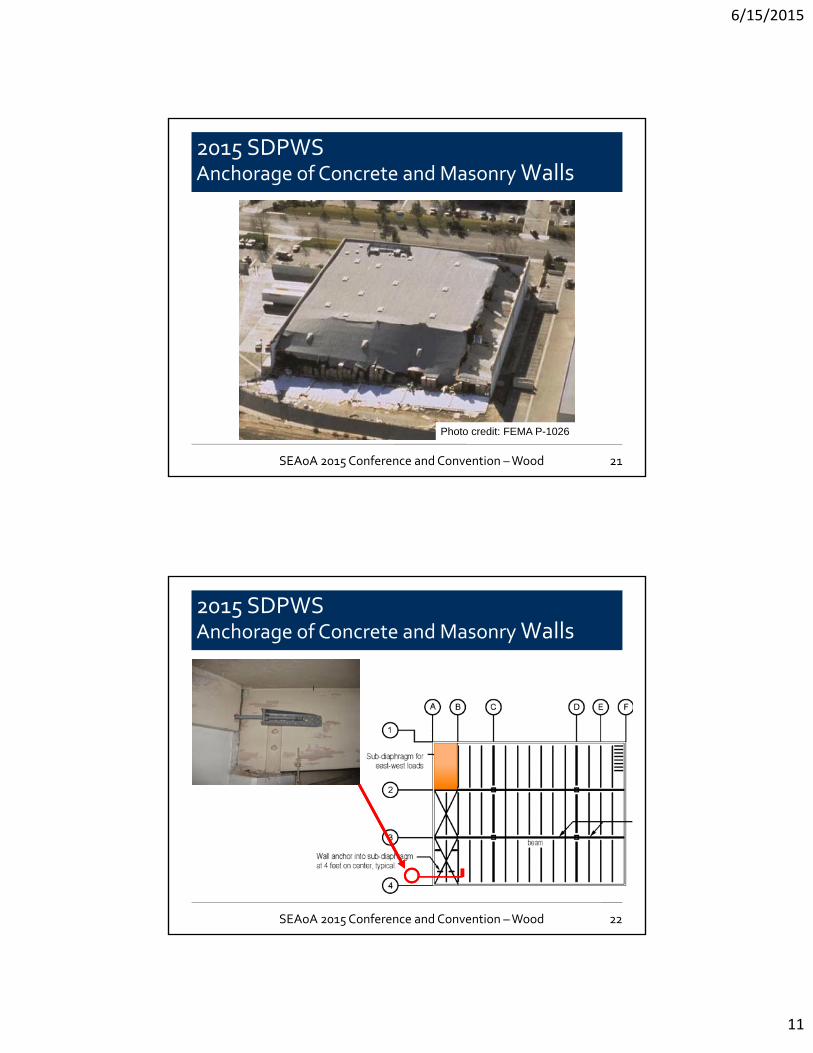
2015 SDPWS Anchorage of Concrete and Masonry Walls
21
Photo credit: FEMA P-1026
SEAoA 2015 Conference and Convention –Wood
2015 SDPWS Anchorage of Concrete and Masonry Walls
22SEAoA 2015 Conference and Convention –Wood
6/15/2015
12
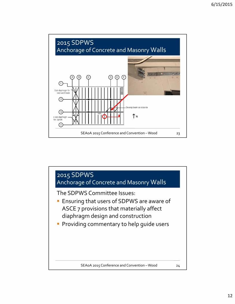
2015 SDPWS Anchorage of Concrete and Masonry Walls
23SEAoA 2015 Conference and Convention –Wood
2015 SDPWS Anchorage of Concrete and Masonry Walls
The SDPWS Committee Issues:
Ensuring that users of SDPWS are aware of ASCE 7 provisions that materially affect diaphragm design and construction
Providing commentary to help guide users
24SEAoA 2015 Conference and Convention –Wood
6/15/2015
13
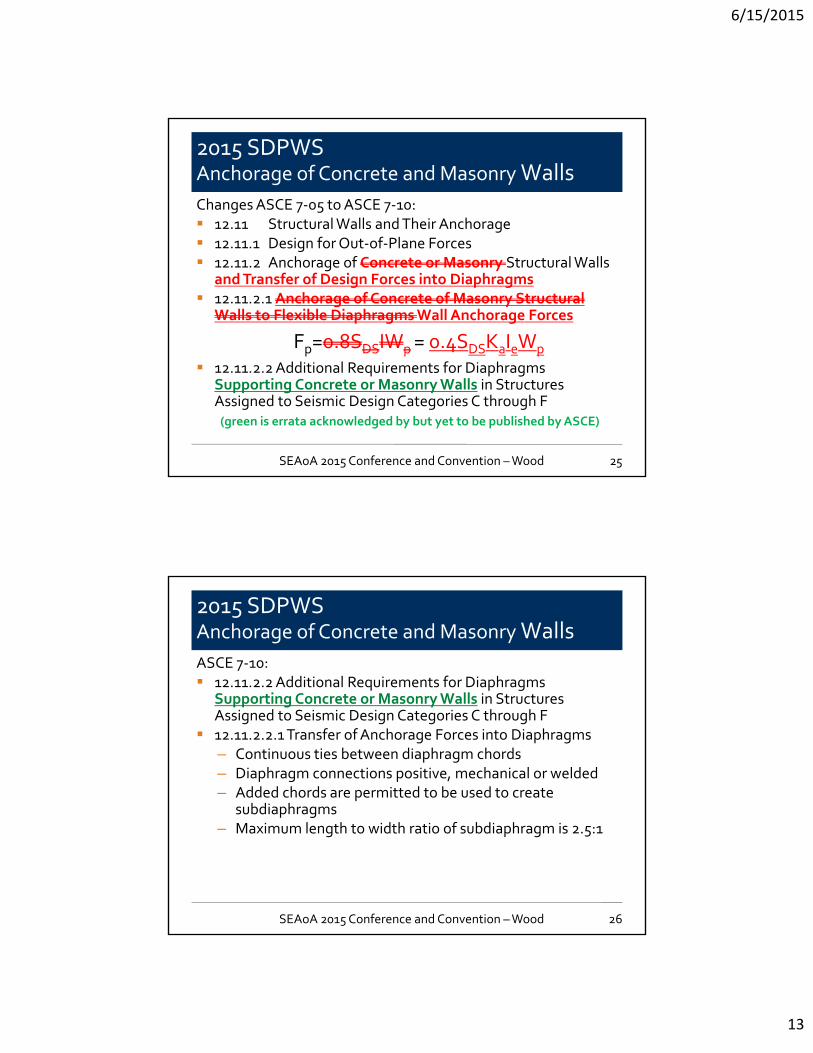
2015 SDPWS Anchorage of Concrete and Masonry WallsChanges ASCE 7‐05 to ASCE 7‐10: 12.11 Structural Walls and Their Anchorage 12.11.1 Design for Out‐of‐Plane Forces 12.11.2 Anchorage of Concrete or Masonry Structural Walls
and Transfer of Design Forces into Diaphragms 12.11.2.1 Anchorage of Concrete of Masonry Structural
Walls to Flexible Diaphragms Wall Anchorage Forces
Fp=0.8SDSIWp= 0.4SDSKaIeWp
12.11.2.2 Additional Requirements for Diaphragms Supporting Concrete or Masonry Walls in Structures Assigned to Seismic Design Categories C through F(green is errata acknowledged by but yet to be published by ASCE)
25SEAoA 2015 Conference and Convention –Wood
2015 SDPWS Anchorage of Concrete and Masonry WallsASCE 7‐10: 12.11.2.2 Additional Requirements for Diaphragms
Supporting Concrete or Masonry Walls in Structures Assigned to Seismic Design Categories C through F
12.11.2.2.1 Transfer of Anchorage Forces into Diaphragms– Continuous ties between diaphragm chords– Diaphragm connections positive, mechanical or welded– Added chords are permitted to be used to create
subdiaphragms– Maximum length to width ratio of subdiaphragm is 2.5:1
26SEAoA 2015 Conference and Convention –Wood
6/15/2015
14
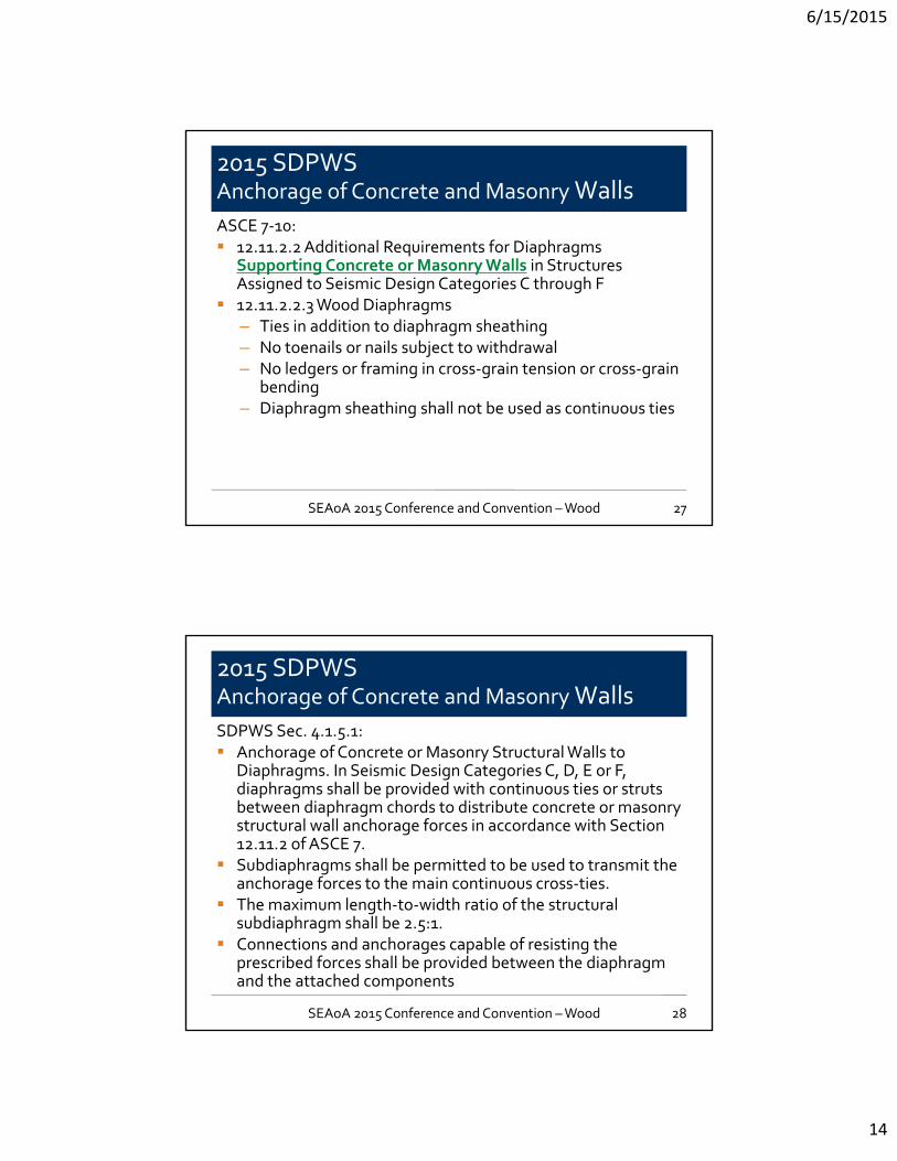
2015 SDPWS Anchorage of Concrete and Masonry WallsASCE 7‐10: 12.11.2.2 Additional Requirements for Diaphragms
Supporting Concrete or Masonry Walls in Structures Assigned to Seismic Design Categories C through F
12.11.2.2.3 Wood Diaphragms– Ties in addition to diaphragm sheathing– No toenails or nails subject to withdrawal– No ledgers or framing in cross‐grain tension or cross‐grain
bending– Diaphragm sheathing shall not be used as continuous ties
27SEAoA 2015 Conference and Convention –Wood
2015 SDPWS Anchorage of Concrete and Masonry WallsSDPWS Sec. 4.1.5.1: Anchorage of Concrete or Masonry Structural Walls to
Diaphragms. In Seismic Design Categories C, D, E or F, diaphragms shall be provided with continuous ties or struts between diaphragm chords to distribute concrete or masonry structural wall anchorage forces in accordance with Section 12.11.2 of ASCE 7.
Subdiaphragms shall be permitted to be used to transmit the anchorage forces to the main continuous cross‐ties.
The maximum length‐to‐width ratio of the structural subdiaphragm shall be 2.5:1.
Connections and anchorages capable of resisting the prescribed forces shall be provided between the diaphragm and the attached components
28SEAoA 2015 Conference and Convention –Wood
6/15/2015
15
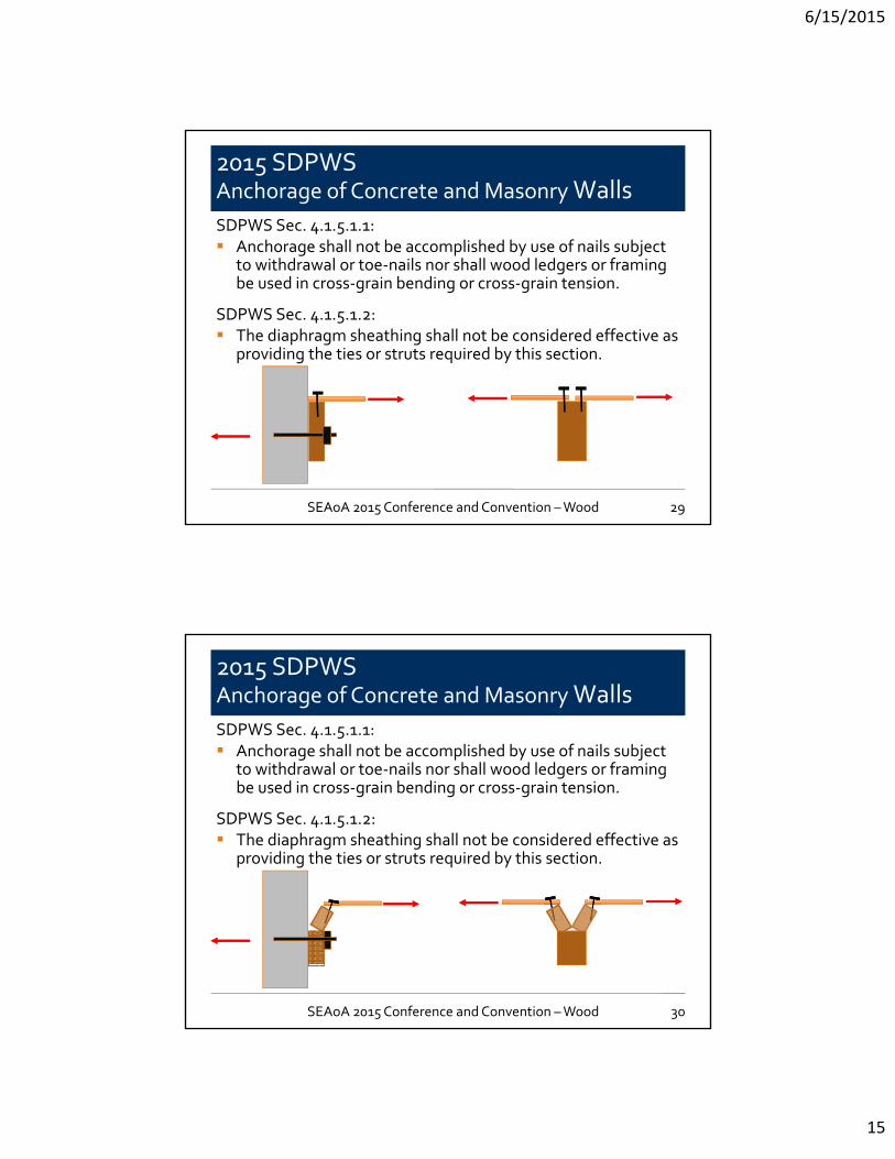
2015 SDPWS Anchorage of Concrete and Masonry WallsSDPWS Sec. 4.1.5.1.1: Anchorage shall not be accomplished by use of nails subject
to withdrawal or toe‐nails nor shall wood ledgers or framing be used in cross‐grain bending or cross‐grain tension.
SDPWS Sec. 4.1.5.1.2: The diaphragm sheathing shall not be considered effective as
providing the ties or struts required by this section.
29SEAoA 2015 Conference and Convention –Wood
2015 SDPWS Anchorage of Concrete and Masonry WallsSDPWS Sec. 4.1.5.1.1: Anchorage shall not be accomplished by use of nails subject
to withdrawal or toe‐nails nor shall wood ledgers or framing be used in cross‐grain bending or cross‐grain tension.
SDPWS Sec. 4.1.5.1.2: The diaphragm sheathing shall not be considered effective as
providing the ties or struts required by this section.
30SEAoA 2015 Conference and Convention –Wood
6/15/2015
16
2015 SDPWS Horizontal Distribution of Shear
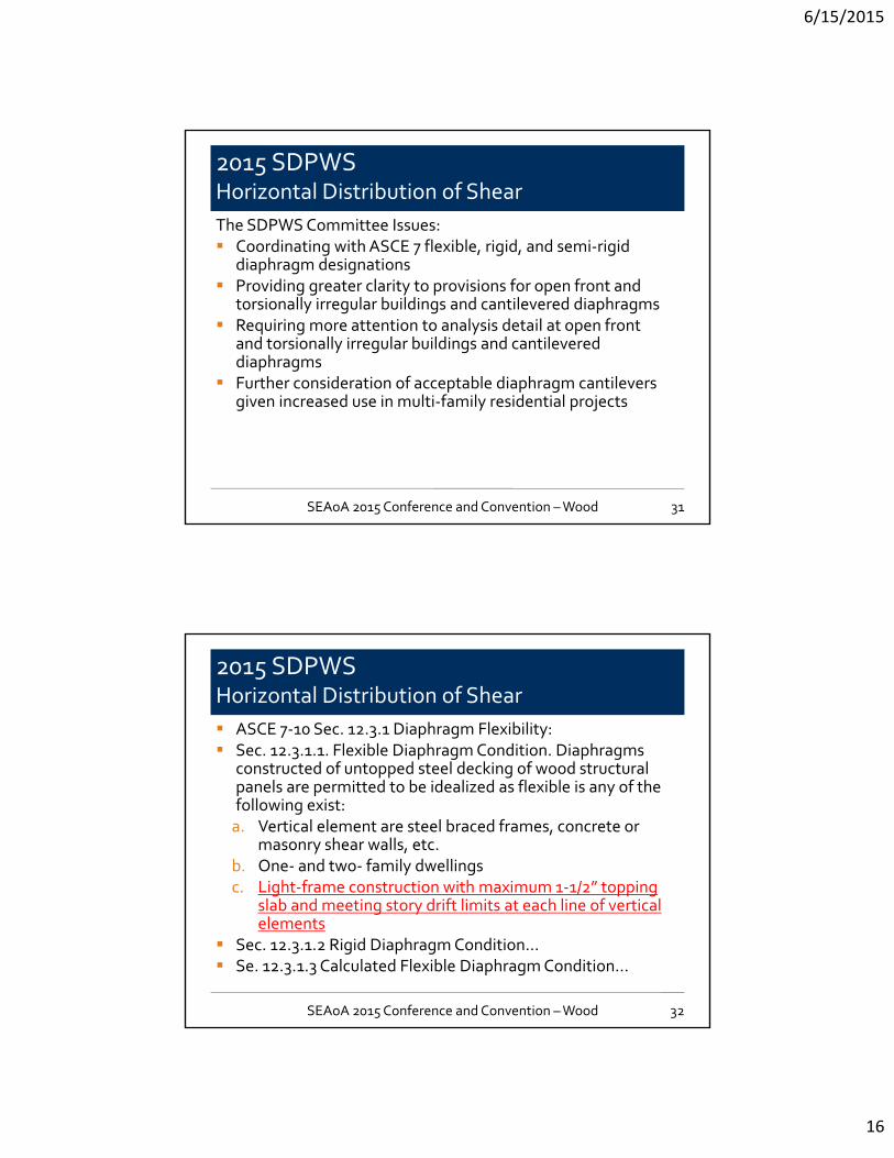
The SDPWS Committee Issues: Coordinating with ASCE 7 flexible, rigid, and semi‐rigid
diaphragm designations Providing greater clarity to provisions for open front and
torsionally irregular buildings and cantilevered diaphragms Requiring more attention to analysis detail at open front
and torsionally irregular buildings and cantilevered diaphragms
Further consideration of acceptable diaphragm cantilevers given increased use in multi‐family residential projects
31SEAoA 2015 Conference and Convention –Wood
2015 SDPWS Horizontal Distribution of Shear
ASCE 7‐10 Sec. 12.3.1 Diaphragm Flexibility: Sec. 12.3.1.1. Flexible Diaphragm Condition. Diaphragms
constructed of untopped steel decking of wood structural panels are permitted to be idealized as flexible is any of the following exist:a. Vertical element are steel braced frames, concrete or
masonry shear walls, etc.b. One‐ and two‐ family dwellingsc. Light‐frame construction with maximum 1‐1/2” topping
slab and meeting story drift limits at each line of vertical elements
Sec. 12.3.1.2 Rigid Diaphragm Condition… Se. 12.3.1.3 Calculated Flexible Diaphragm Condition...
32SEAoA 2015 Conference and Convention –Wood
6/15/2015
17
2015 SDPWS Horizontal Distribution of Shear
SDPWS Sec. 4.2.5:– Distribution of shear to vertical elements based on
analysis where diaphragm is modeled as semi‐rigid, idealized as flexible, or idealized as rigid
– Where idealized as flexible, based on tributary area– When idealized as rigid, based on relative stiffness of
vertical elements– When not idealized as rigid or flexible, distribute based
on relative stiffness of diaphragm and vertical elements– In lieu of semi‐rigid, envelope method may be used
33SEAoA 2015 Conference and Convention –Wood
2015 SDPWS Horizontal Distribution of Shear
SDPWS Sec. 4.2.5.1 Torsional Irregularity: Structures with wood‐frame diaphragms modeled as semi‐
rigid or idealized as rigid shall be considered as torsionally irregular under seismic load when the maximum story drift, computed from seismic design forces including accidental torsion, at the end of the structure is more than 1.2 items the average of the story drifts at the two ends of the structure. When a torsional irregularity exists in structures assigned to SDC B, C, D, E of F, diaphragm shall meet all of the following requirements:– Wood structural panel or diagonal lumber sheathed– L/W<=1.5 wood structural panel, <=1 diagonal lumber– Maximum story drift checked at each edge of structure
34SEAoA 2015 Conference and Convention –Wood
6/15/2015
18
2015 SDPWS Horizontal Distribution of Shear
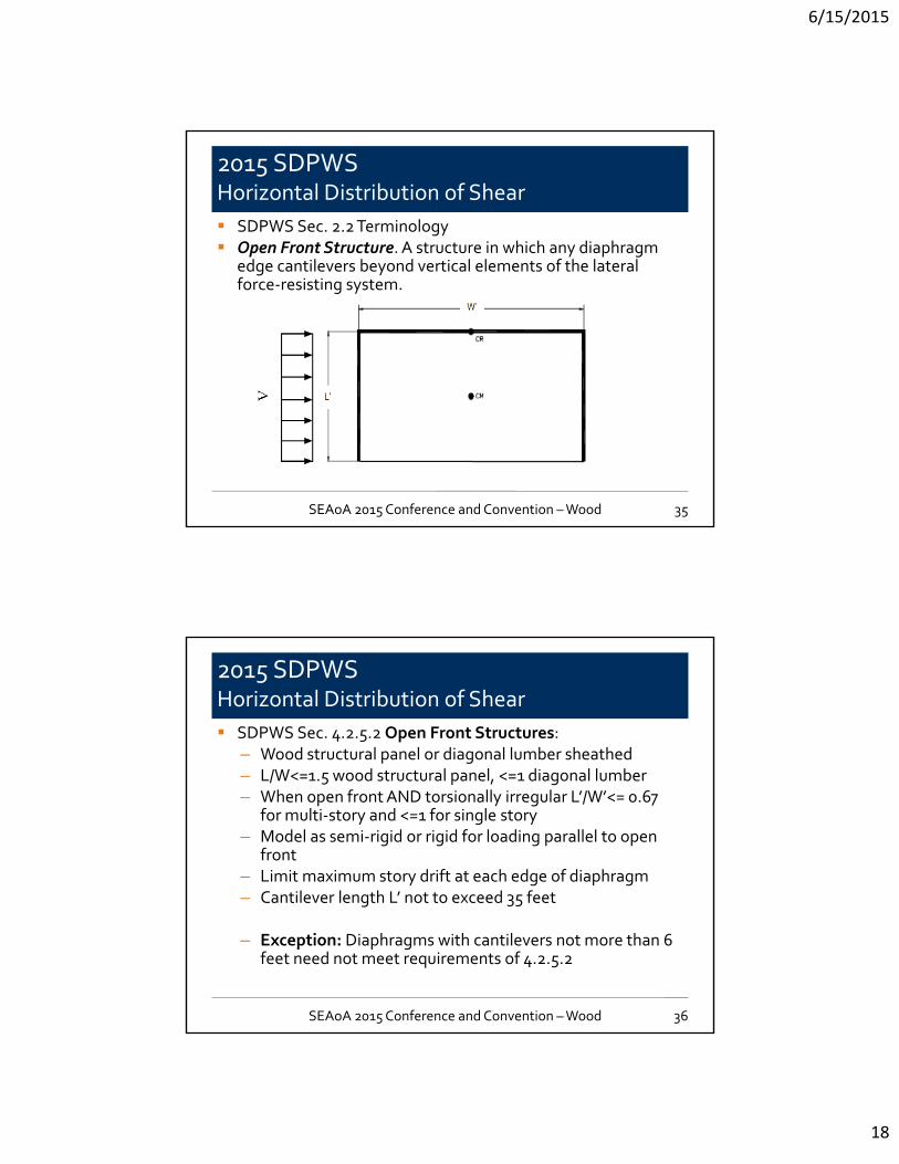
SDPWS Sec. 2.2 Terminology Open Front Structure. A structure in which any diaphragm
edge cantilevers beyond vertical elements of the lateral force‐resisting system.
35SEAoA 2015 Conference and Convention –Wood
2015 SDPWS Horizontal Distribution of Shear
SDPWS Sec. 4.2.5.2 Open Front Structures:– Wood structural panel or diagonal lumber sheathed– L/W<=1.5 wood structural panel, <=1 diagonal lumber– When open front AND torsionally irregular L’/W’<= 0.67
for multi‐story and <=1 for single story – Model as semi‐rigid or rigid for loading parallel to open
front– Limit maximum story drift at each edge of diaphragm– Cantilever length L’ not to exceed 35 feet
– Exception: Diaphragms with cantilevers not more than 6 feet need not meet requirements of 4.2.5.2
36SEAoA 2015 Conference and Convention –Wood

6/15/2015
19
2015 SDPWSHorizontal distribution of shear
Practical Limits: Diaphragm not
permitted to be classified as flexible for purposes of force distribution to vertical elements when diaphragm cantilevers greater than six feet
Sheathing limits Aspect ratio limits 35 foot maximum
diaphragm cantilever
37SEAoA 2015 Conference and Convention –Wood
2015 SDPWSHorizontal distribution of shear
Calculating diaphragm deflection at open front
38SEAoA 2015 Conference and Convention –Wood
6/15/2015
20
2015 SDPWS Force distribution to shear walls in a line
SDPWS Committee Issues:
2005, 2008 SDPWS method for distributing forces between walls in a line differed from common design practice
Need clarity for distribution where wall lines include slender walls
39SEAoA 2015 Conference and Convention –Wood
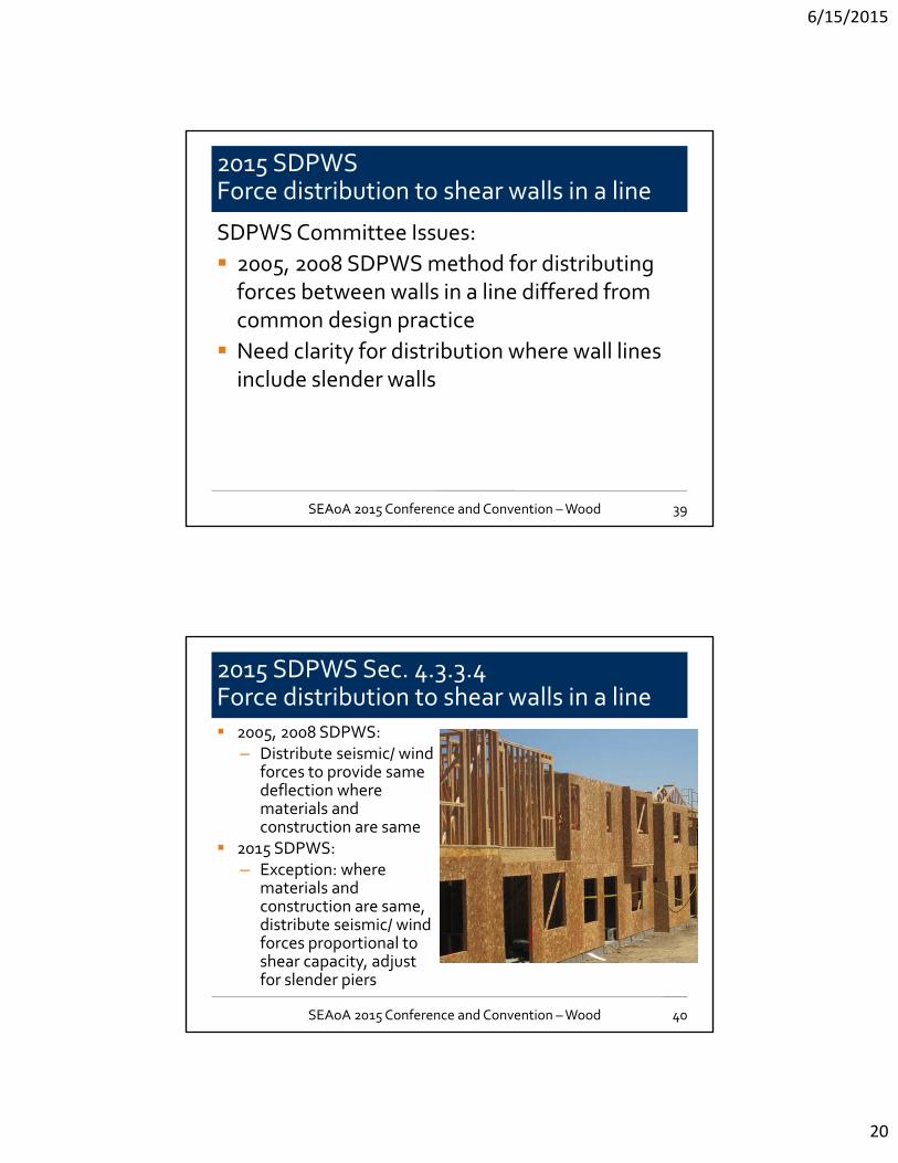
2015 SDPWS Sec. 4.3.3.4Force distribution to shear walls in a line 2005, 2008 SDPWS:
– Distribute seismic/ wind forces to provide same deflection where materials and construction are same
2015 SDPWS:– Exception: where
materials and construction are same, distribute seismic/ wind forces proportional to shear capacity, adjust for slender piers
40SEAoA 2015 Conference and Convention –Wood
6/15/2015
21
2015 SDPWS Sec. 4.3.3.4 & 4.3.4Shear walls with narrow piers Narrow wall pier capacity
adjustment (multiplier) for force distribution to walls in a line:– Wood structural panel>2:1
2bs/h– Fiberboard>1:1
0.1 + 0.9bs/h Narrow wall pier capacity
adjustment (multiplier):– Wood structural panel>2:1
1.25 – 0.125h/bs
– Fiberboard>1:1 1.09 – 0.09h/bs
41
Need not be used in addition to force distribution multiplier
SEAoA 2015 Conference and Convention –Wood
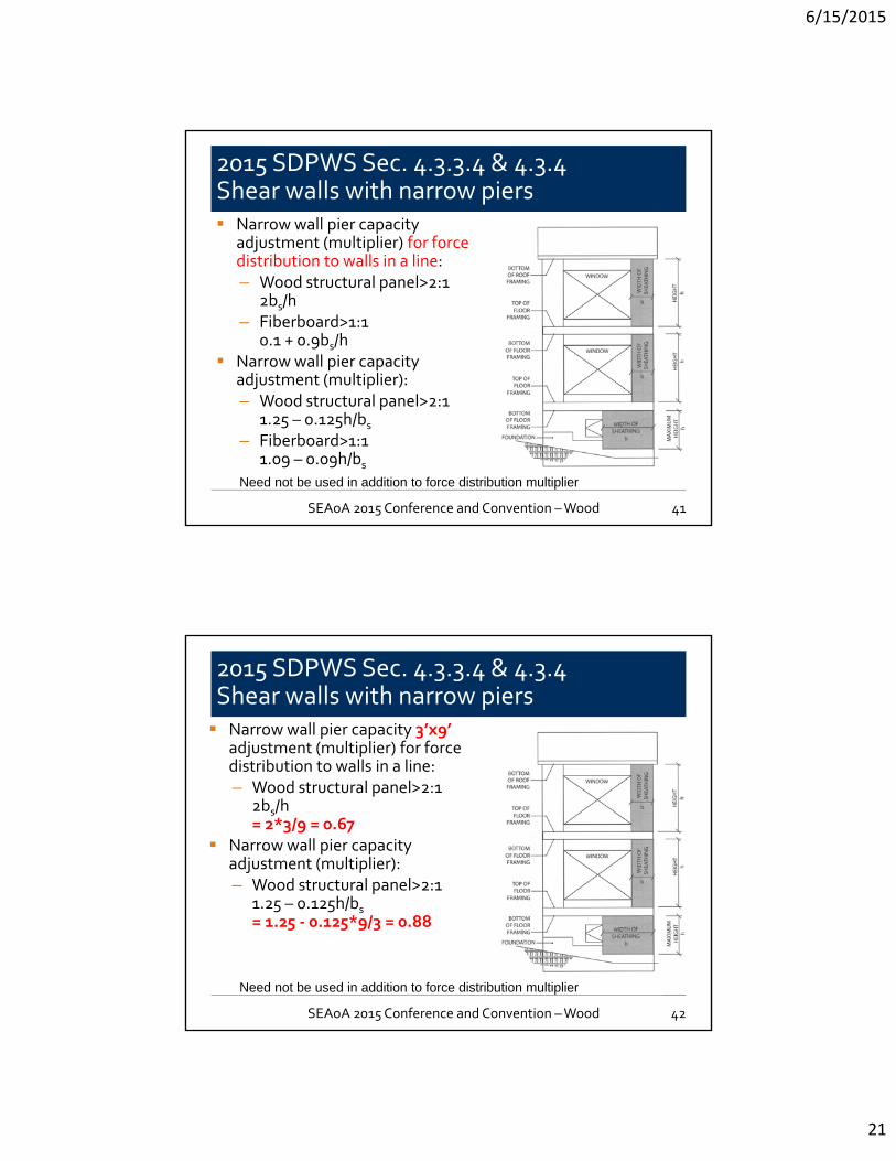
2015 SDPWS Sec. 4.3.3.4 & 4.3.4Shear walls with narrow piers Narrow wall pier capacity 3’x9’
adjustment (multiplier) for force distribution to walls in a line:– Wood structural panel>2:1
2bs/h = 2*3/9 = 0.67
Narrow wall pier capacity adjustment (multiplier):– Wood structural panel>2:1
1.25 – 0.125h/bs = 1.25 ‐ 0.125*9/3 = 0.88
42
Need not be used in addition to force distribution multiplier
SEAoA 2015 Conference and Convention –Wood

6/15/2015
22
ASCE 7‐16 Chapter 12:
Alternative Provisions for Diaphragms Including Chords and Collectors
Alternative Provisions for Diaphragms Including Chords and Collectors
BSSC IT‐06 Committee Issues: Rodriguez and Restrepo study of diaphragm force levels,
vertical distribution of forces Higher forces than current code (when near‐elastic) Diaphragm forces limited by vertical element
overstrength, 0, in first mode, but not necessarily for higher mode behavior
Precast concrete industry post‐Northridge development of seismic design methodology for precast concrete diaphragms
1997 UBC consideration of “real” demand and capacity for vertical elements, but not for diaphragms
44SEAoA 2015 Conference and Convention –Wood 44
6/15/2015
23
Alternative Provisions for Diaphragms Including Chords and Collectors
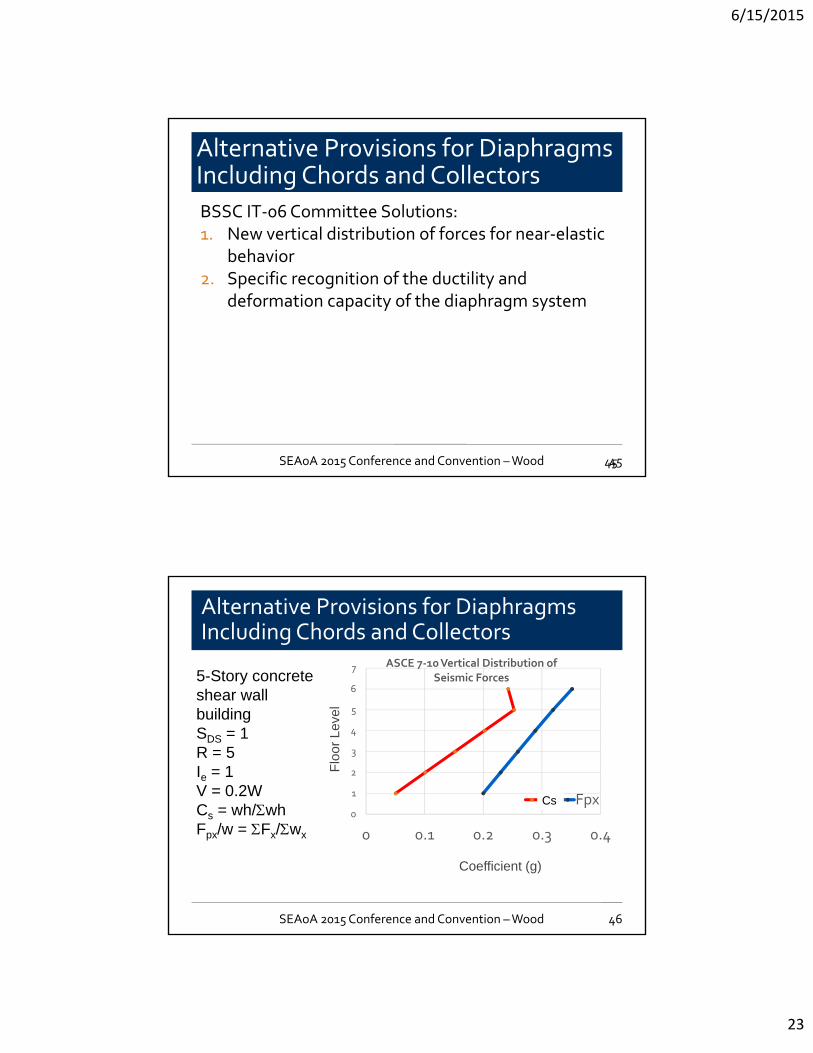
BSSC IT‐06 Committee Solutions:1. New vertical distribution of forces for near‐elastic
behavior2. Specific recognition of the ductility and
deformation capacity of the diaphragm system
45SEAoA 2015 Conference and Convention –Wood 45
Alternative Provisions for Diaphragms Including Chords and Collectors
Coefficient (g)
Flo
or L
evel
0
1
2
3
4
5
6
7
0 0.1 0.2 0.3 0.4
ASCE 7‐10 Vertical Distribution of Seismic Forces
Fx Fpx
5-Story concrete shear wall buildingSDS = 1R = 5Ie = 1V = 0.2WCs = wh/whFpx/w = Fx/wx
Cs
SEAoA 2015 Conference and Convention –Wood 46
6/15/2015
24
Diaphragm Design Force
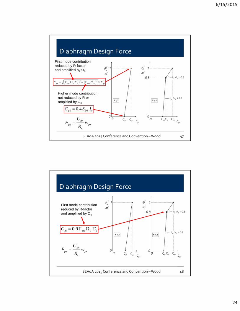
0 0.4p DS eC S I
2 2
1 0 2 2pn m s m s piC C C C
First mode contribution reduced by R-factor and amplified by 0
Higher mode contribution not reduced by R or amplified by 0
pxpx px
s
CF = w
R
SEAoA 2015 Conference and Convention –Wood 47
Diaphragm Design Force
First mode contribution reduced by R-factor and amplified by 0
pxpx px
s
CF = w
R
1 00 9pi m sC . C
SEAoA 2015 Conference and Convention –Wood 48
6/15/2015
25
Alternative Provisions for Diaphragms Including Chords and Collectors
Coefficient (g)
Flo
or L
evel
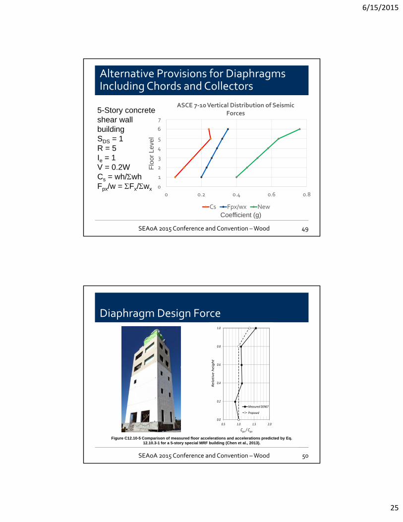
5-Story concrete shear wall buildingSDS = 1R = 5Ie = 1V = 0.2WCs = wh/whFpx/w = Fx/wx 0
1
2
3
4
5
6
7
0 0.2 0.4 0.6 0.8
ASCE 7‐10 Vertical Distribution of Seismic Forces
Cs Fpx/wx New
SEAoA 2015 Conference and Convention –Wood 49
Diaphragm Design Force
0.0
0.2
0.4
0.6
0.8
1.0
0.5 1.0 1.5 2.0
Relative height
Cpx / Cpo
Measured DEN67
Proposed
Figure C12.10-5 Comparison of measured floor accelerations and accelerations predicted by Eq. 12.10.3-1 for a 5-story special MRF building (Chen et al., 2013).
SEAoA 2015 Conference and Convention –Wood 50
6/15/2015
26
Diaphragm Design Force
0.0
0.2
0.4
0.6
0.8
1.0
0.5 1.0 1.5
Relative height
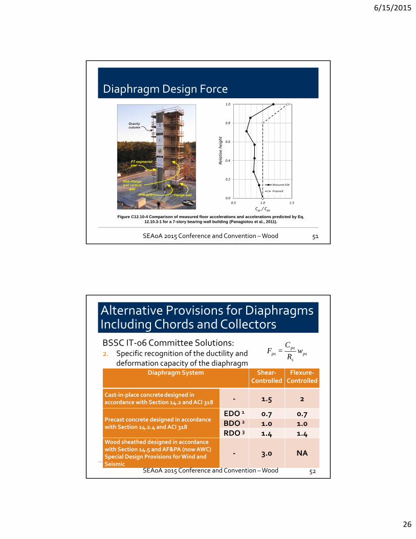
Cpx / Cpo
Measured EQ4
Proposed
Figure C12.10-4 Comparison of measured floor accelerations and accelerations predicted by Eq. 12.10.3-1 for a 7-story bearing wall building (Panagiotou et al., 2011).
SEAoA 2015 Conference and Convention –Wood 51
Alternative Provisions for Diaphragms Including Chords and Collectors
BSSC IT‐06 Committee Solutions:2. Specific recognition of the ductility and
deformation capacity of the diaphragm system
52
Diaphragm System Shear‐Controlled
Flexure‐Controlled
Cast‐in‐place concretedesigned in accordance with Section 14.2 and ACI 318 ‐ 1.5 2
Precast concrete designed in accordance with Section 14.2.4 and ACI 318
EDO 1 0.7 0.7BDO 2 1.0 1.0RDO 3 1.4 1.4
Wood sheathed designed in accordance with Section 14.5 and AF&PA (now AWC) Special Design Provisions for Wind and Seismic
‐ 3.0 NA
pxpx px
s
CF = w
R
SEAoA 2015 Conference and Convention –Wood
6/15/2015
27
Alternative Provisions for Diaphragms Including Chords and Collectors
Coefficient (g)
Flo
or L
evel
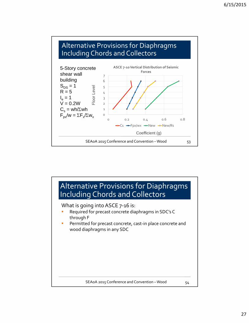
5-Story concrete shear wall buildingSDS = 1R = 5Ie = 1V = 0.2WCs = wh/whFpx/w = Fx/wx
0
1
2
3
4
5
6
7
0 0.2 0.4 0.6 0.8
ASCE 7‐10 Vertical Distribution of Seismic Forces
Cs Fpx/wx New New/Rs
SEAoA 2015 Conference and Convention –Wood 53
Alternative Provisions for Diaphragms Including Chords and Collectors
What is going into ASCE 7‐16 is: Required for precast concrete diaphragms in SDC’s C
through F Permitted for precast concrete, cast‐in place concrete and
wood diaphragms in any SDC
54SEAoA 2015 Conference and Convention –Wood
6/15/2015
28
FEMA P‐1026:
Seismic Design of Rigid Wall –Flexible Diaphragm Buildings:
An Alternate Approach
Seismic Design of Rigid Wall – Flexible Diaphragm Buildings: An Alternate Approach
56
Principal Authors:Dominic Kelly, SGHJohn Lawson, Cal Poly SLO
SEAoA 2015 Conference and Convention –Wood
6/15/2015
29
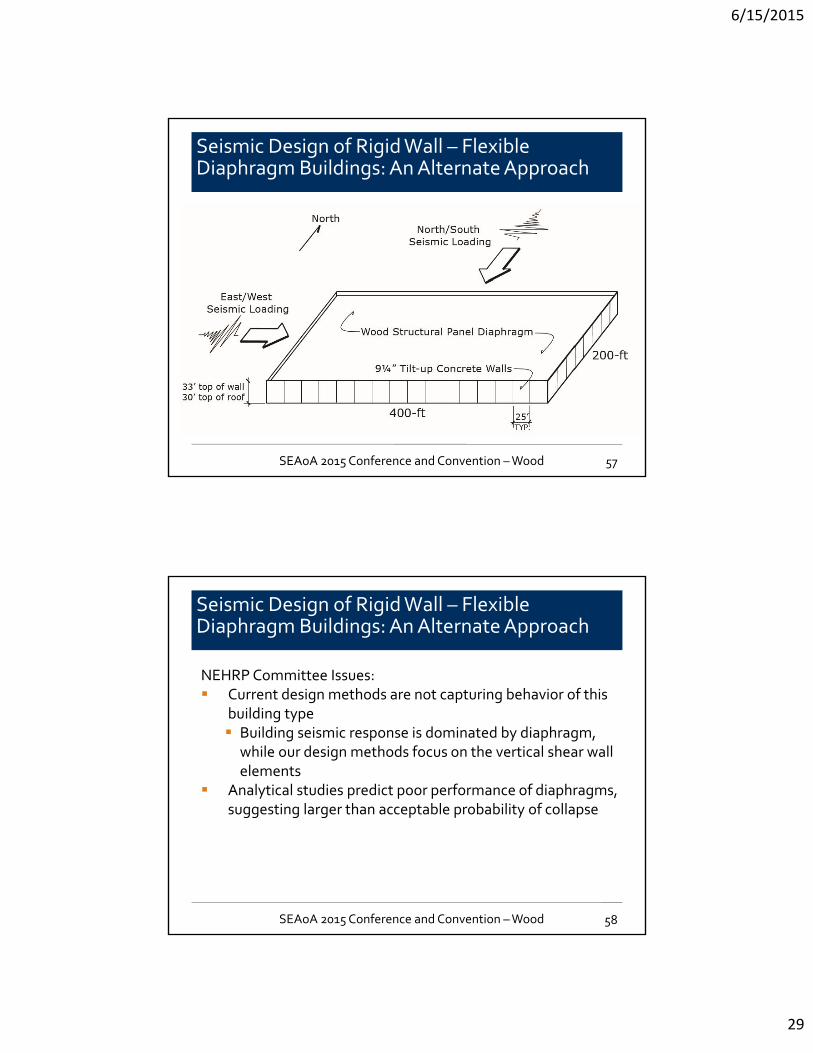
Seismic Design of Rigid Wall – Flexible Diaphragm Buildings: An Alternate Approach
57SEAoA 2015 Conference and Convention –Wood
Seismic Design of Rigid Wall – Flexible Diaphragm Buildings: An Alternate Approach
NEHRP Committee Issues: Current design methods are not capturing behavior of this
building type Building seismic response is dominated by diaphragm,
while our design methods focus on the vertical shear wall elements
Analytical studies predict poor performance of diaphragms, suggesting larger than acceptable probability of collapse
58SEAoA 2015 Conference and Convention –Wood
6/15/2015
30
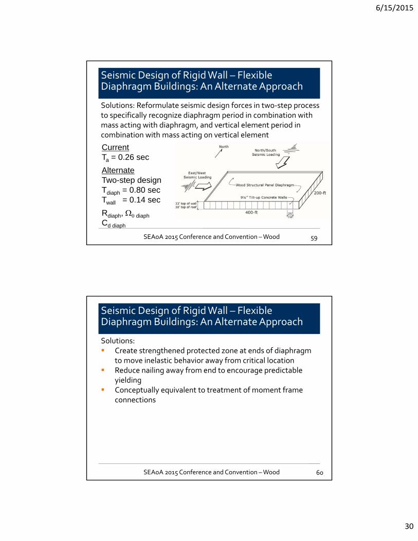
Seismic Design of Rigid Wall – Flexible Diaphragm Buildings: An Alternate Approach
Solutions: Reformulate seismic design forces in two‐step process to specifically recognize diaphragm period in combination with mass acting with diaphragm, and vertical element period in combination with mass acting on vertical element
59
CurrentTa = 0.26 sec
AlternateTwo-step designTdiaph = 0.80 secTwall = 0.14 sec
Rdiaph, diaph
Cd diaph
SEAoA 2015 Conference and Convention –Wood
Seismic Design of Rigid Wall – Flexible Diaphragm Buildings: An Alternate Approach
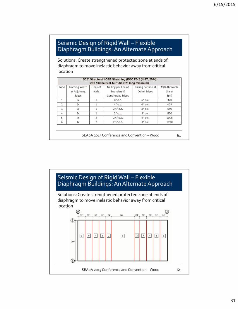
Solutions: Create strengthened protected zone at ends of diaphragm
to move inelastic behavior away from critical location Reduce nailing away from end to encourage predictable
yielding Conceptually equivalent to treatment of moment frame
connections
60SEAoA 2015 Conference and Convention –Wood
6/15/2015
31
Seismic Design of Rigid Wall – Flexible Diaphragm Buildings: An Alternate Approach
Solutions: Create strengthened protected zone at ends of diaphragm to move inelastic behavior away from critical location
61SEAoA 2015 Conference and Convention –Wood
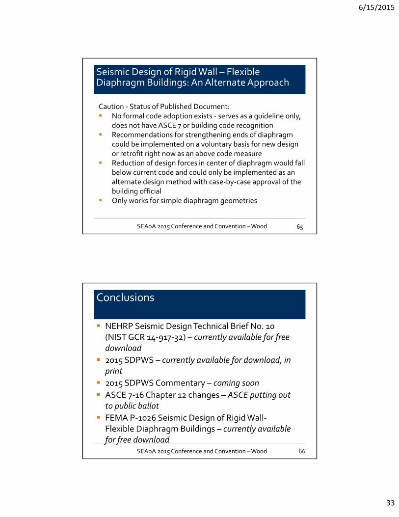
Seismic Design of Rigid Wall – Flexible Diaphragm Buildings: An Alternate Approach
Solutions: Create strengthened protected zone at ends of diaphragm to move inelastic behavior away from critical location
62SEAoA 2015 Conference and Convention –Wood

6/15/2015
32
Seismic Design of Rigid Wall – Flexible Diaphragm Buildings: An Alternate Approach
Solutions: Create strengthened protected zone at ends of diaphragm to move inelastic behavior away from critical location
63SEAoA 2015 Conference and Convention –Wood
Seismic Design of Rigid Wall – Flexible Diaphragm Buildings: An Alternate Approach
Solutions: Create strengthened protected zone at ends of diaphragm to move inelastic behavior away from critical location
64SEAoA 2015 Conference and Convention –Wood
6/15/2015
33
Seismic Design of Rigid Wall – Flexible Diaphragm Buildings: An Alternate Approach
Caution ‐ Status of Published Document: No formal code adoption exists ‐ serves as a guideline only,
does not have ASCE 7 or building code recognition Recommendations for strengthening ends of diaphragm
could be implemented on a voluntary basis for new design or retrofit right now as an above code measure
Reduction of design forces in center of diaphragm would fall below current code and could only be implemented as an alternate design method with case‐by‐case approval of the building official
Only works for simple diaphragm geometries
65SEAoA 2015 Conference and Convention –Wood
Conclusions
NEHRP Seismic Design Technical Brief No. 10 (NIST GCR 14‐917‐32) – currently available for free download
2015 SDPWS – currently available for download, in print
2015 SDPWS Commentary – coming soon
ASCE 7‐16 Chapter 12 changes – ASCE putting out to public ballot
FEMA P‐1026 Seismic Design of Rigid Wall‐Flexible Diaphragm Buildings – currently available for free download
66SEAoA 2015 Conference and Convention –Wood
6/15/2015
34
End Parts 1‐4
Questions?
Rigger’s Loft Historic Preservation
and Wind/ Seismic Upgrade

6/15/2015
35
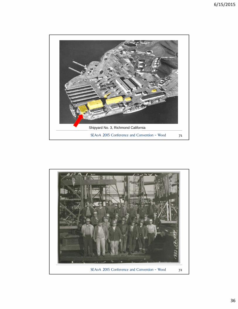
Riggers Loft RehabilitationRigger’s LoftShipyard No. 3 Richmond CaliforniaProject for: Port of RichmondContractor: Alten ConstructionHistoric Preservation Architect: WJEStructural Engineer: WJEMEP: ACIESGeotechnical Engineer: Langan/ Treadwell & RolloOriginal Design: Kaiser, March 1942
SEAoA 2015 Conference and Convention – Wood 69
Shipyard No. 3, Richmond California
SEAoA 2015 Conference and Convention – Wood 70
6/15/2015
36
Shipyard No. 3, Richmond California
SEAoA 2015 Conference and Convention – Wood 71
SEAoA 2015 Conference and Convention – Wood 72
6/15/2015
37
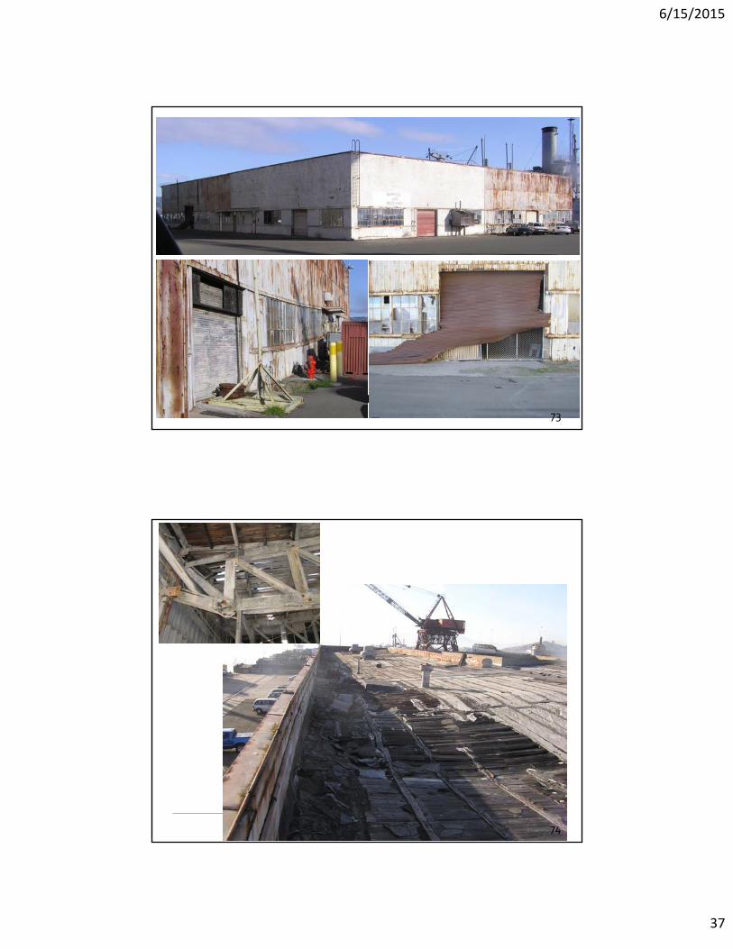
WJE Riggers Loft Rehabilitation, Shipyard No. 3, Richmond California
73
Riggers Loft Rehabilitation, Shipyard No. 3, Richmond California
74
6/15/2015
38
Riggers Loft Rehabilitation, Shipyard No. 3, Richmond California
75
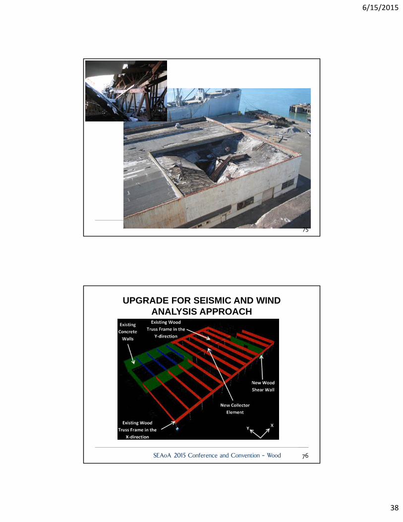
UPGRADE FOR SEISMIC AND WINDANALYSIS APPROACH
SEAoA 2015 Conference and Convention – Wood 76
6/15/2015
39
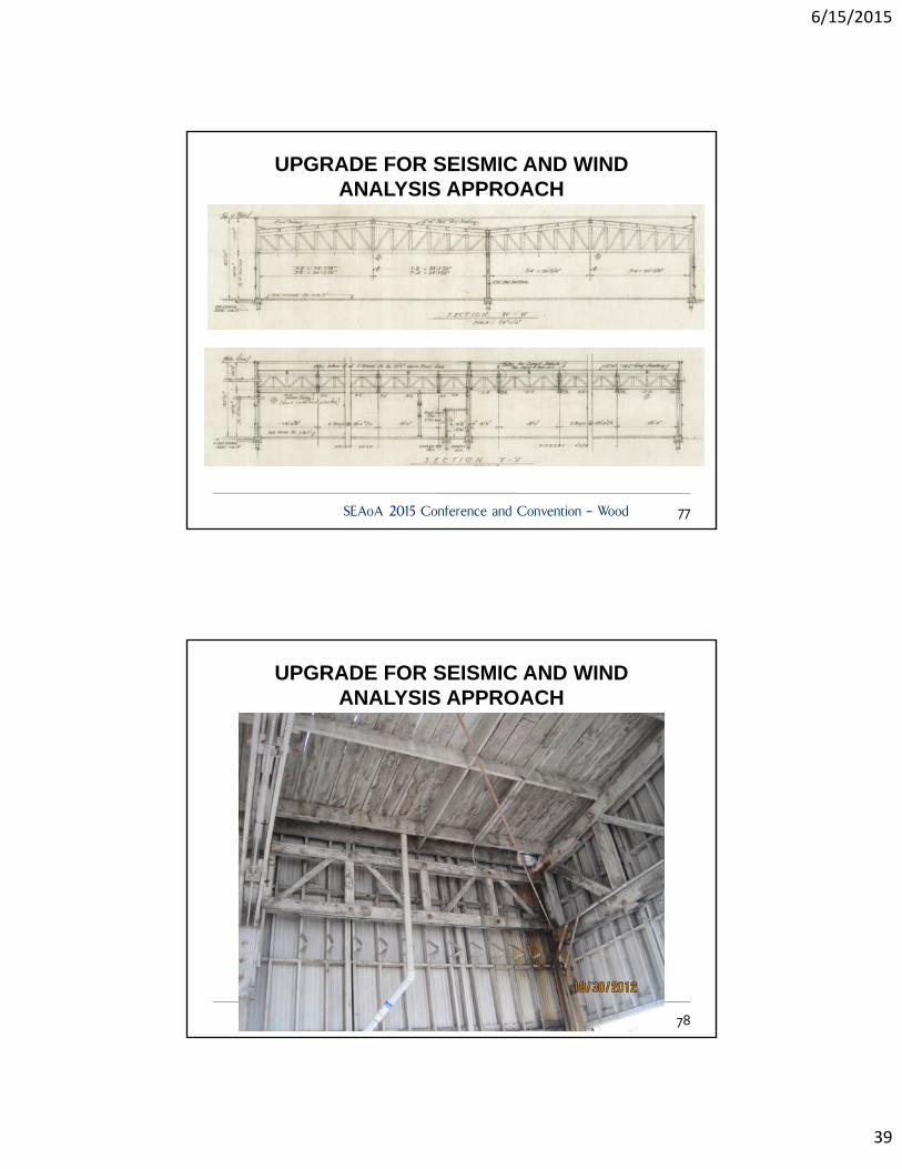
UPGRADE FOR SEISMIC AND WINDANALYSIS APPROACH
SEAoA 2015 Conference and Convention – Wood 77
Shipyard No. 3, Richmond California
UPGRADE FOR SEISMIC AND WINDANALYSIS APPROACH
78

6/15/2015
40
UPGRADE FOR SEISMIC AND WINDANALYSIS APPROACH
SEAoA 2015 Conference and Convention – Wood 79
UPGRADE FOR SEISMIC AND WINDINCREASED DIAPHRAGM STRENGTH AND STIFFNESS
SEAoA 2015 Conference and Convention – Wood 80
6/15/2015
41
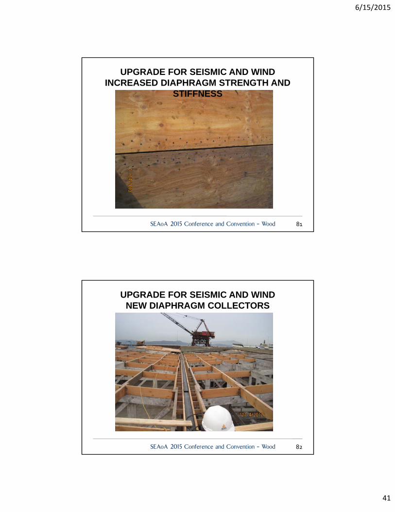
UPGRADE FOR SEISMIC AND WINDINCREASED DIAPHRAGM STRENGTH AND
STIFFNESS
SEAoA 2015 Conference and Convention – Wood 81
UPGRADE FOR SEISMIC AND WINDNEW DIAPHRAGM COLLECTORS
SEAoA 2015 Conference and Convention – Wood 82

6/15/2015
42
UPGRADE FOR SEISMIC AND WINDNEW DIAPHRAGM COLLECTORS
SEAoA 2015 Conference and Convention – Wood 83
UPGRADE FOR SEISMIC AND WINDNEW SHEAR WALL
SEAoA 2015 Conference and Convention – Wood 84
6/15/2015
43
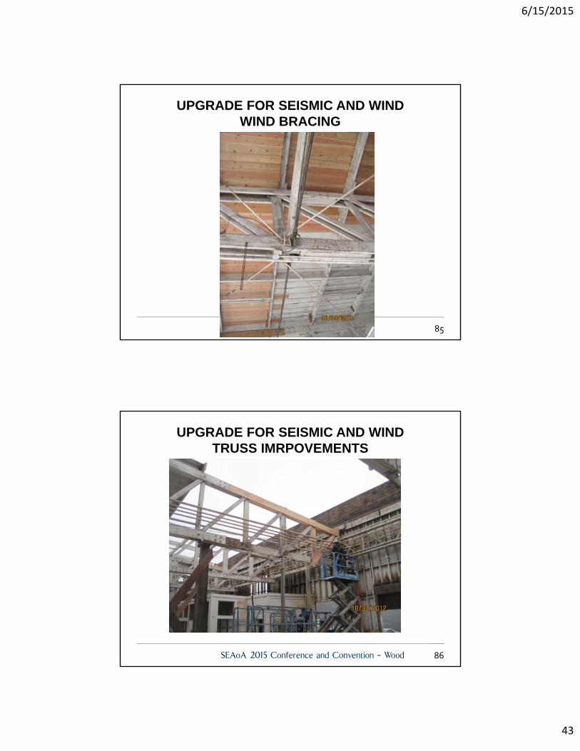
UPGRADE FOR SEISMIC AND WINDWIND BRACING
85
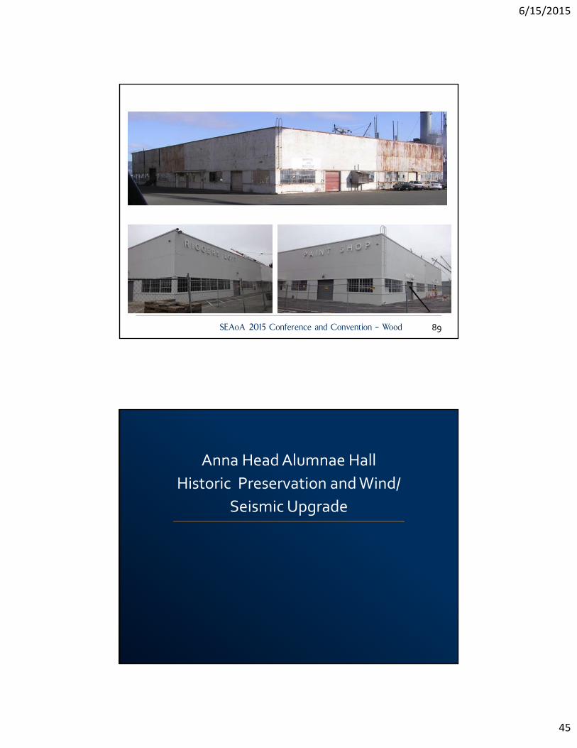
UPGRADE FOR SEISMIC AND WINDTRUSS IMRPOVEMENTS
SEAoA 2015 Conference and Convention – Wood 86

6/15/2015
44
UPGRADE FOR SEISMIC AND WINDTRUSS IMRPOVEMENTS
SEAoA 2015 Conference and Convention – Wood 87
UPGRADE FOR SEISMIC AND WINDTRUSS IMRPOVEMENTS
SEAoA 2015 Conference and Convention – Wood 88
6/15/2015
45
END Thank You
SEAoA 2015 Conference and Convention – Wood 89
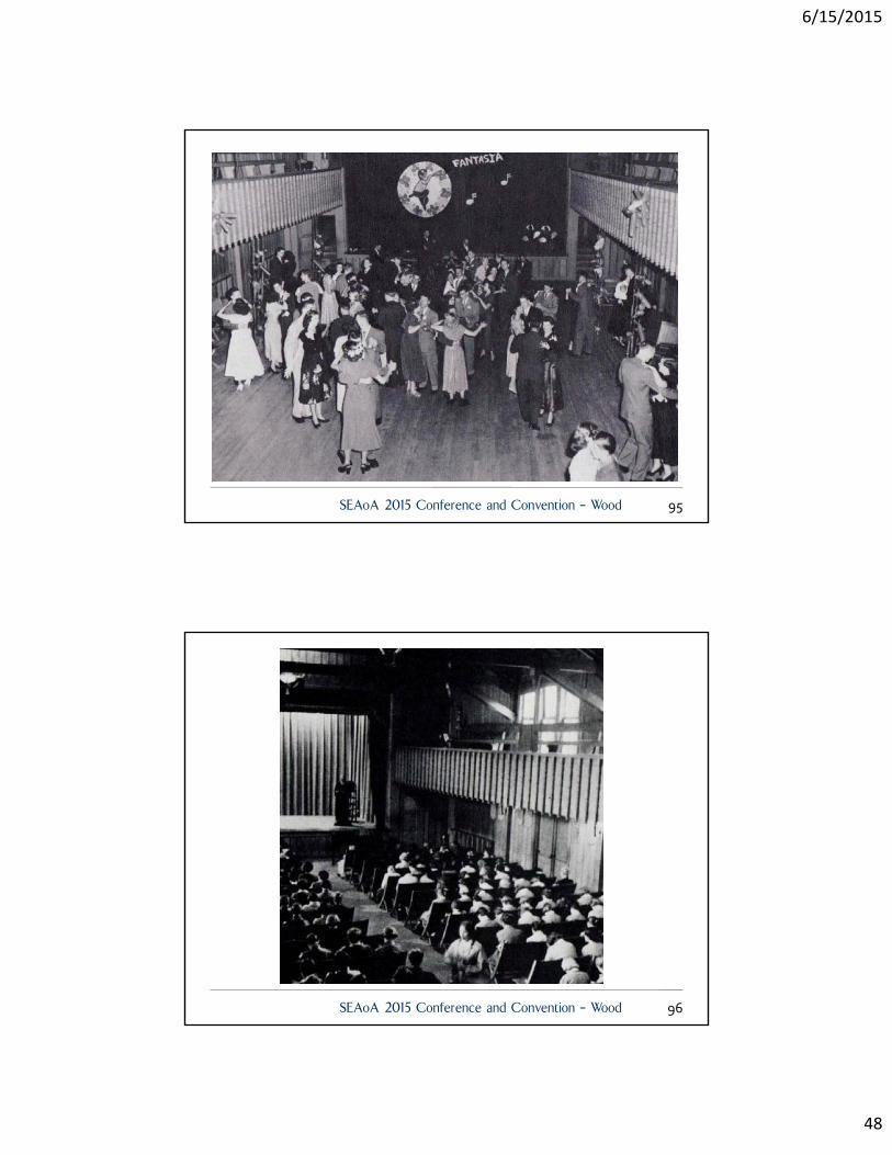
Anna Head Alumnae Hall
Historic Preservation and Wind/
Seismic Upgrade
6/15/2015
46
Anna Head Alumni HallAnna Head Alumnae HallProject for: UC BerkeleyContractor: BHM ConstructionHistoric Preservation Architect: Cody Anderson WasneyStructural Engineer: WJE
Original Architect:W.H. Ratcliff, 1926
SEAoA 2015 Conference and Convention – Wood 91
SEAoA 2015 Conference and Convention – Wood 92

6/15/2015
47
WJE Shipyard No. 3, Richmond California
UPGRADE FOR SEISMIC AND WIND
93
94
6/15/2015
48
SEAoA 2015 Conference and Convention – Wood 95
SEAoA 2015 Conference and Convention – Wood 96
6/15/2015
49
WJE
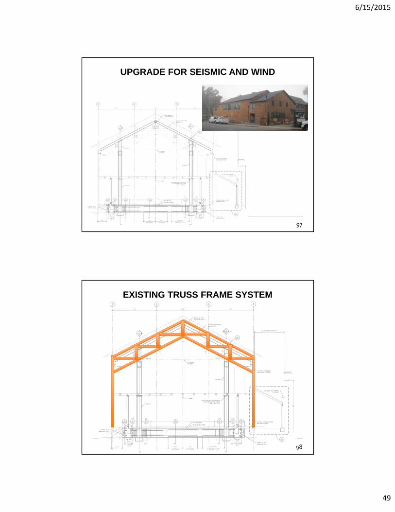
UPGRADE FOR SEISMIC AND WIND
97
WJE
EXISTING TRUSS FRAME SYSTEM
98
6/15/2015
50
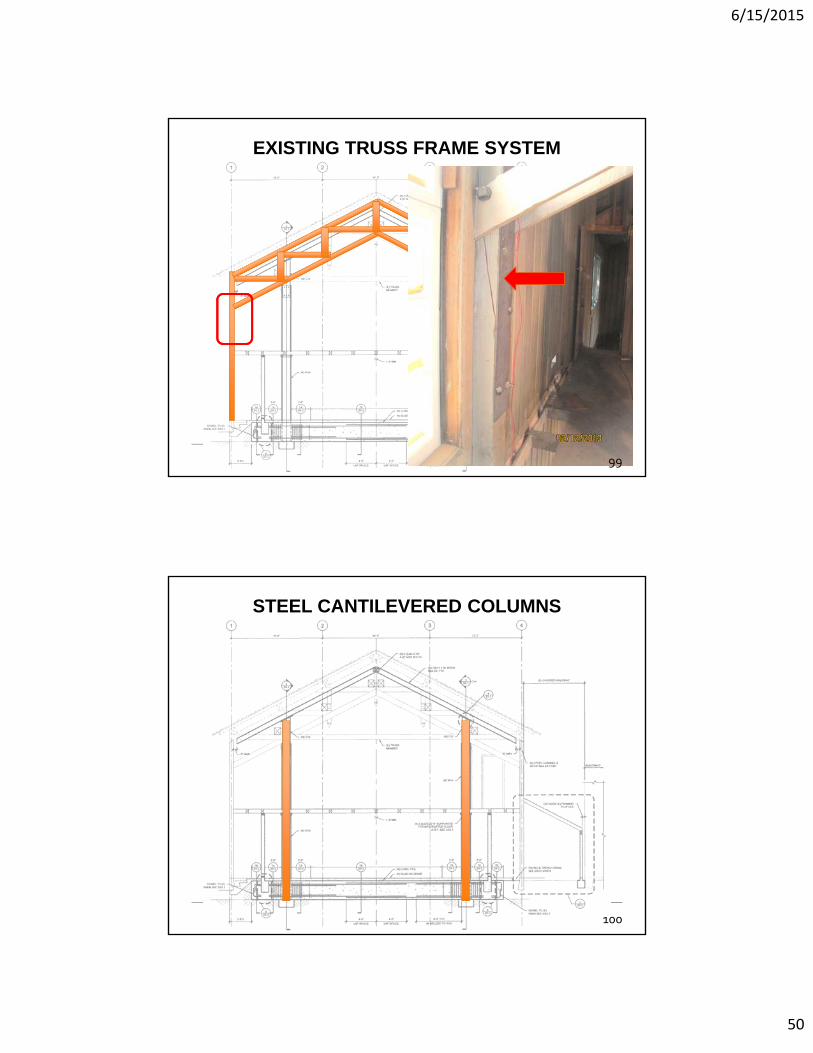
WJE
EXISTING TRUSS FRAME SYSTEM
99
WJE
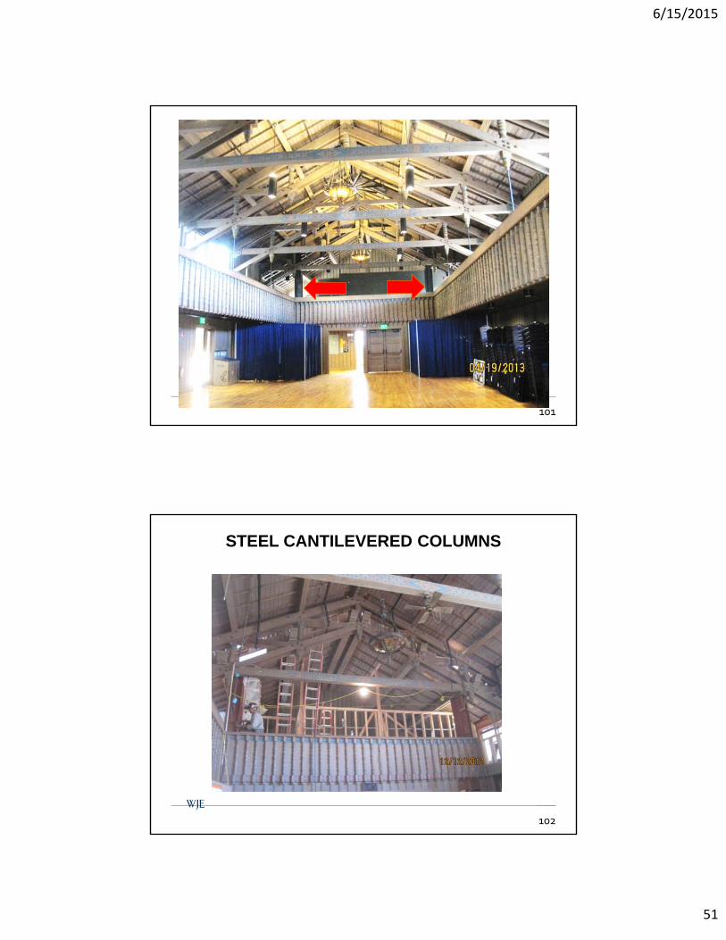
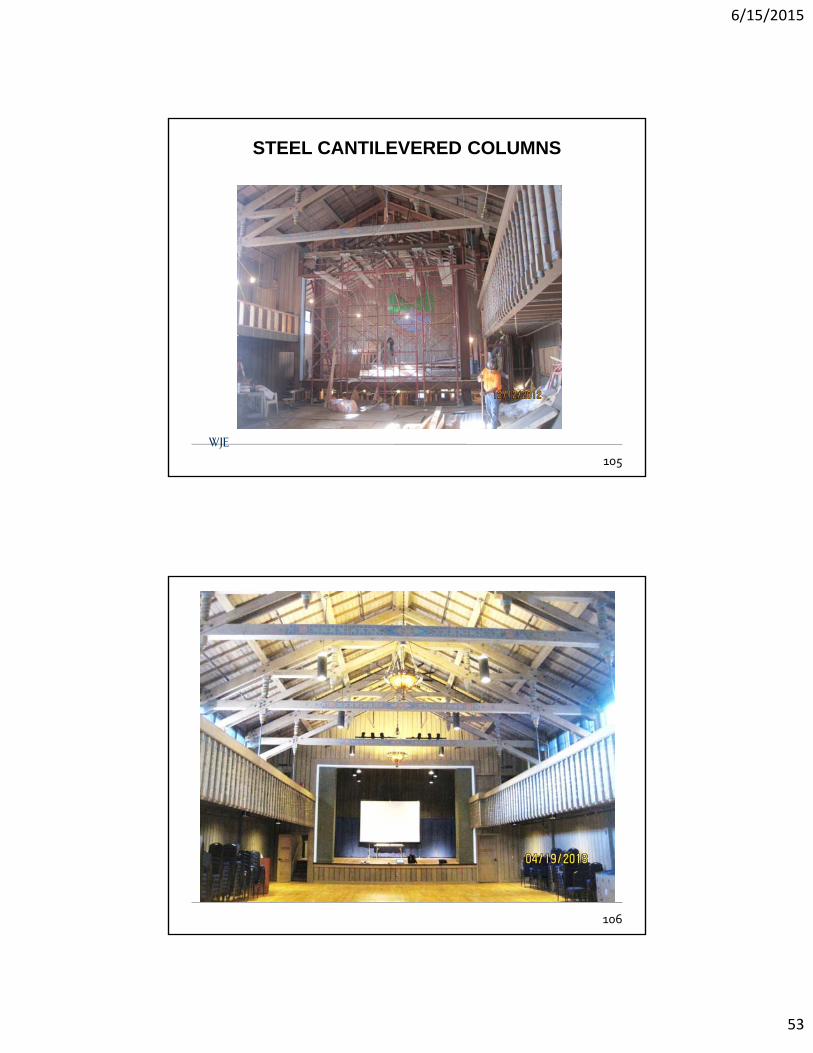
STEEL CANTILEVERED COLUMNS
100
6/15/2015
51
WJE Shipyard No. 3, Richmond California
UPGRADE FOR SEISMIC AND WIND
101
WJE
STEEL CANTILEVERED COLUMNS
102
6/15/2015
52
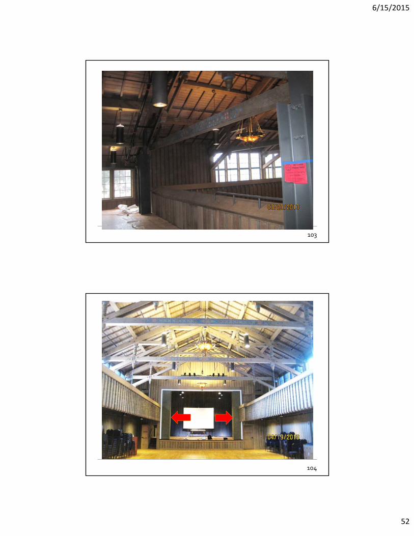
WJE Shipyard No. 3, Richmond California
UPGRADE FOR SEISMIC AND WIND
103
104
6/15/2015
53
WJE
STEEL CANTILEVERED COLUMNS
105
106
6/15/2015
54
WJE
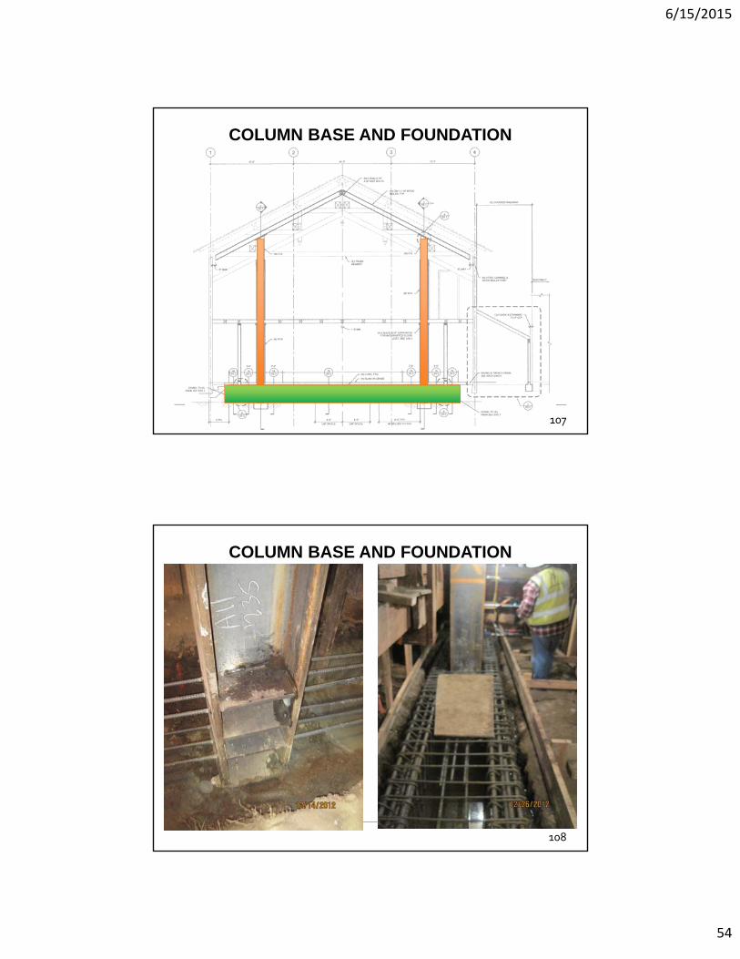
COLUMN BASE AND FOUNDATION
107
WJE
COLUMN BASE AND FOUNDATION
108

6/15/2015
55
WJE
COLLECTOR
109
COLLECTOR
110

6/15/2015
56
ROOF DIAPHRAGM
SEAoA 2015 Conference and Convention – Wood 111
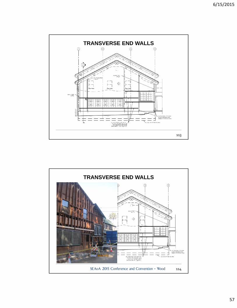
TRANSVERSE END WALLS
112
6/15/2015
57
TRANSVERSE END WALLS
113
TRANSVERSE END WALLS
SEAoA 2015 Conference and Convention – Wood 114
6/15/2015
58
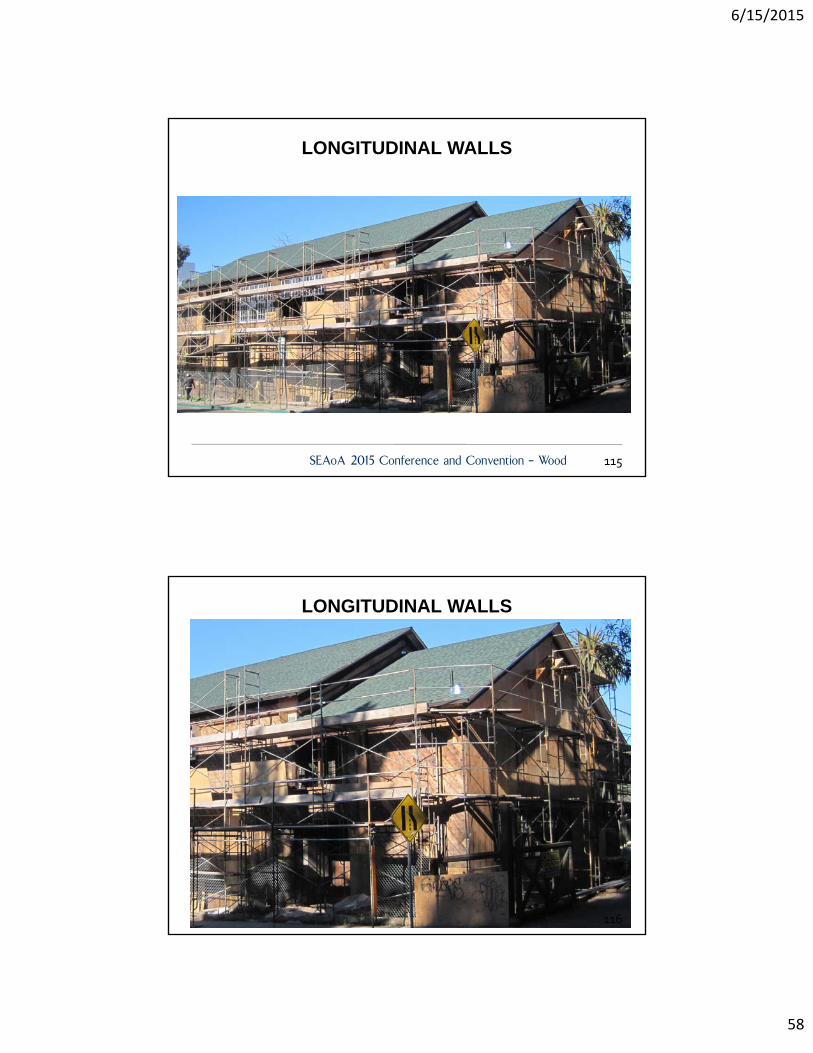
LONGITUDINAL WALLS
SEAoA 2015 Conference and Convention – Wood 115
LONGITUDINAL WALLS
116
6/15/2015
59
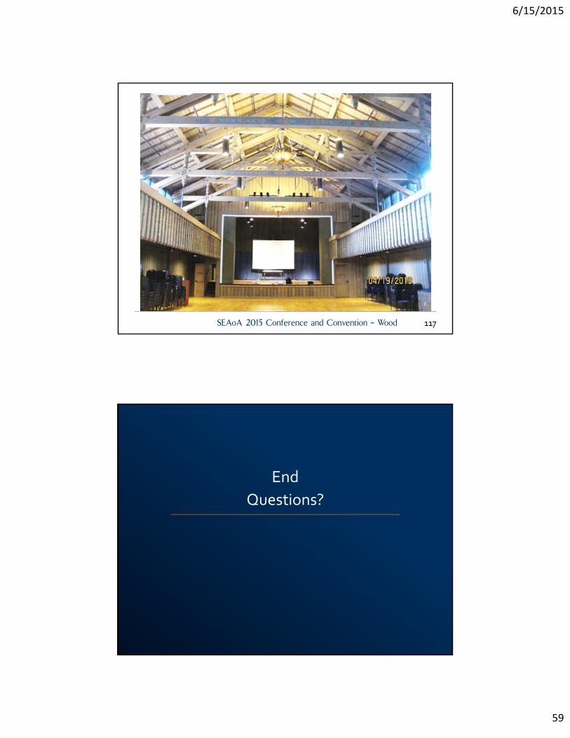
SEAoA 2015 Conference and Convention – Wood 117
End
Questions?