recent developments of cooling tower design
TRANSCRIPT

Proceedings of the International Association for Shell and Spatial Structures (IASS) Symposium 2009, Valencia Evolution and Trends in Design, Analysis and Construction of Shell and Spatial Structures
28 September – 2 October 2009, Universidad Politecnica de Valencia, Spain Alberto DOMINGO and Carlos LAZARO (eds.)
Recent developments of cooling tower design Reinhard HARTE*, Udo WITTEKa
* IASS Working Group 3
Bergische Universität Wuppertal, Pauluskirchstraße 7, D 42285 Wuppertal, Germany [email protected]
a IASS Working Group 3
Universität Kaiserslautern, Erwin-Schrödinger-Straße, D 67663 Kaiserslautern, Germany [email protected]
Abstract Natural draught cooling towers (NDCT) are the characterizing landmarks of power stations. They contribute both to an efficient energy output and to a careful balance with our environment. In the last decade the building of new power plants stagnated all over the world. Nowadays the German power suppliers have started an extensive renewal program, where old units will be replaced by new ones, which will be much cleaner and more efficient. Besides innovative boiler techniques the sustainable and reliable design and construction of cooling towers are focussed both by research and industry. The goal is to determine and implement strategies that insure an adequate level of safety and durability at the lowest possible life-cycle cost. Further, the implementation of new European and German codes for the design and proof of reinforced concrete structures required a revision of the VGB Guideline “Structural Design of Cooling Towers” (BTR – Bautechnik bei Kühltürmen), which since many years served as the theoretical and practical tool to design and build cooling towers all over the world. In 2005, a revised version has been elaborated, where the partial safety concepts acc. EC 1 and EC 2 and the respective German codes have been considered, and where the application of nonlinear design tools and the requirements with respect to sustainable durability have been improved (VGB 2005 [11]). The paper presents the main features of this new VGB-guideline. Further it gives an overview over running and planned cooling tower projects in Germany, with special focus on technical innovations. Finally it summarizes some results of actual research projects, exploring the effects of progressive damaging and high-performance concrete on design, stability and durability of cooling tower shells. Keywords: cooling tower, partial safety concept, ultimate limit design, progressive damage, high-performance concrete, VGB guideline.
198

Proceedings of the International Association for Shell and Spatial Structures (IASS) Symposium 2009, Valencia Evolution and Trends in Design, Analysis and Construction of Shell and Spatial Structures
1. Introduction Natural draught cooling towers are most effective measures for cooling of thermal power plants by minimising the need of water and avoiding thermal pollution of natural water bodies. Thus they are able to balance environmental factors, investments and operating costs with the demands of a reliable energy supply.
36 Columns 47 Columns36 Columns 36 Columns 40 Columns1999 2005-2008 2007-2008 2007-2008 2008-2010
o 11
.00
166.50
116.50
40.74
9.85
2 NDCTs Westfalen D/E
NDCT Niederaußem K
12.18
49.00
200.00
142.00
o 9.
00
2 NDCTs Neurath F/G
10.35
58.40
173.20
137.00
o 12
.00
NDCT Boxberg R
8.33
36.00
155.00
o 8.
00
107.00
NDCT Datteln 4
10.44
48.70
178.10
118.44
o 11
.00
Figure 1: Recent German cooling tower projects.
Cooling towers in fossil fired power plants mostly do not only perform the refrigeration of the cooling water, they as well can be used for the discharge of the cleaned flue-gases, with the benefit to completely save a chimney. This is a speciality of modern European power plants. Figure 1 gives an impression about the last cooling tower projects already built or under construction in Germany. The power plants will have a total electrical power of about 6 GW and are fired by lignite coal (Boxberg, Neurath and Niederaußem) or hard coal (Datteln and Hamm). Further projects of hard coal fired power plants in Moorburg, Lünen, Wilhelmshaven, Mainz, Maasvlakte, Antwerpen and Staudinger are projected or under construction and exposed to be finished till 2014 – a giant power plant renewal program for Germany.
199

Proceedings of the International Association for Shell and Spatial Structures (IASS) Symposium 2009, Valencia Evolution and Trends in Design, Analysis and Construction of Shell and Spatial Structures
2. Recent developments in cooling tower design Most of the actual German cooling towers use the benefit of discharging the flue-gas via the cooling tower. The reasons are given by environmental requirements. By law, the flue-gas from fossil-fired units needs to be cleaned from sulphur by washing in an alkaline-liquid. This process cools down the flue-gas with the consequence of loosing the thermodynamic energy to further disperse it by the chimney. Thus in the past existing cooling towers have already been retrofitted in that way that the cleaned flue-gas was introduced into the natural draught (airflow) of cooling towers via large pipes (Eckstein et al. [2]). Since 1996 this introduction is performed at a high elevation using the shell wall as support (Figure 1). This optimises the efficiency of the flue-gas disperse by avoiding bends in the pipes due and thus reducing the flow resistance (Harte and Krätzig [4]). The introduction of the cleaned flue-gases into the cooling tower is connected with one disadvantage: Because of residual sulphur in the gas, the inner surface of the shell is attacked by low concentrated acid vapour. To meet this, special acid resistant high performance concrete mixtures have been developed. The resulting compact packing of the aggregate combined with fly-ash and microsilica is an appropriate way to protect the concrete against acid attack (Busch [1]). Further, such high-performance concrete will cause greater thermal stresses of the shell’s cross section, less ductility against dynamic wind action and thus additional cracking problems. This has to be considered in the design and proof of the shell and requires non-linear verifications in addition to the design procedure according to VGB 2005[11]. Further improvements in the numerical modelling of cooling tower shells have been implemented with respect to • consideration of realistic wind action including non-axisymmetric distributions due to
interference effects, as have been evaluated by wind-tunnel tests (Niemann et al. [9]), • consideration of the realistic non-axi-symmetric distribution of the soil characteristics
(Harte and Mahran [6]).
3. The actual VGB-guideline With respect to the new generation of German standards DIN 1045 and DIN 1055, corresponding to EC 1 and EC 2, a revision of the guideline VGB 1997 [10] on the structural design of cooling towers had become necessary. The revised version was published in 2005 and includes further improvements with respect to a safe and reliable structural design: - consideration of partial safety factors, - non-linear analysis strategies, - requirements for increased durability. In the past not only cooling towers in Germany have been designed according to the guideline edition 1997 and its former editions, but the guideline has as well been successfully adopted for numerous cooling tower projects all over the world. Thus it was
200

Proceedings of the International Association for Shell and Spatial Structures (IASS) Symposium 2009, Valencia Evolution and Trends in Design, Analysis and Construction of Shell and Spatial Structures
necessary to provide an English version of the revised edition, which as well has been published by the end of 2005 (VGB 2005 [11]). The structure of the new VGB guideline is focussed on the adaptation of the partial safety concepts of Eurocodes as well as on innovative tools for structural analysis, design and quality control. It comprises four substantial chapters, distinguishing between the cooling tower structure with shell, columns and foundation as the main construction, and the water basin, fill support structure and water distribution system as the remaining buildings. The chapter “Verification of durability - concrete technology” deals with the definition of exposition classes, which determine the requested concrete quality, the composition of concrete, the concrete cover and the requirements for the serviceability calculations. Separated from the nomination of concrete specifications an independent chapter “Quality assurance” at the end of VGB 2005 [11] is dealing with the quality of manufacture with respect to the specifications of a quality control manual, defining construction tolerances, concrete quality limitations, curing of concrete surface etc. The main intention of VGB 2005 [11] is to provide a uniform standard for the safe and reliable design and proof of cooling towers. Thus the chapters “Cooling tower structure” and “Basin, fill support structure and water distribution” specify in detail: Actions, structural analysis methods, safety concept and construction requirements. The new generation of European standards is based on a partial safety concept to verify ultimate limit states (ULS) and serviceability limit states (SLS). To verify the ultimate limit state, both linear and non-linear analysis methods may be applied. Using linear analysis, a cross-section design with stress resultants due to nominal load cases will quantify the reinforcement. Such a cross-section design is also possible using non-linearly calculated stress resultants, or alternatively an ultimate load analysis may be performed (see chapter 4). To verify the serviceability limit state, the limitation of crack width is focussed. The specific variables in general will be calculated linearly. In the revised VGB guideline the characteristic crack width wk is limited to: - shell: wk ≤ 0.20 mm - columns and foundation: wk ≤ 0.30 mm - basin and fill support structure: wk ≤ 0.15 mm In addition to the verification of the different design limit states the revised guideline requires a buckling safety of γB ≥ 5 with respect to characteristic values for the combination of actions G + We + Wi (dead load G, external wind pressure We and internal suction Wi). This high safety factor is necessary to guarantee a sufficient safety margin from stability failure, as imperfections and material degradations, which may heavily influence the overall structural stability, but which are unknown and thus cannot be considered in the design phase. The resulting design procedure is appropriate to determine the wall thickness distribution of the shell, as shown in Figure 2 for the NDCTs in Neurath. Regarding the defined design situations, characteristic values Fk for the essential actions are to be considered:
201

Proceedings of the International Association for Shell and Spatial Structures (IASS) Symposium 2009, Valencia Evolution and Trends in Design, Analysis and Construction of Shell and Spatial Structures
• Dead load G
The specific weight of reinforced concrete is assumed to be 25kN/m3. • Wind load W
The wind load W as a quasi-static load is separated into external pressure We and internal suction Wi.
10.35
137.00
o 12
.00
O 69.68 173.20
O 66.45
O 108.56O 115.74
z
58.40
Wallthickness
Columns
0.30 m0.20 m
1.00 m
0.23 m
0.20 m
r = r + b + (H - z)ab
20
2T
m00.137Hm6221.183bm0090.98am7840.64r
T
0
===
−=Lower Part:
m00.137Hm3596.39bm5032.4am7218.28r
T
0
====
Upper Part:
0.23 m
3.00 m
Figure 2: Dimensions and wall thickness of NDCTs Neurath.
• Temperature T The thermal actions consist of uniform temperature changes T0 and temperature gradients ∆T (difference between inside and outside atmosphere). The following values are defined referring to German site locations: - operational temperature TOP: T0
OP = -15 K ∆TOP = 33 K - summer outage TS: T0
S = 22 K (effective gradient ∆TS) ∆TS = -25 K - winter outage TW: T0
W = -39 K ∆TW = 0
• Shrinkage S An equivalent uniform temperature change of T0 = -15 K may be assumed.
• Indirectly induced soil settlements B Soil settlements in this sense are induced by foreign effects due to underground mining or neighbouring buildings and represent indirect actions.
• Seismic actions AE and accidental actions A Seismic actions or accidental actions may be derived from design values.
202

Proceedings of the International Association for Shell and Spatial Structures (IASS) Symposium 2009, Valencia Evolution and Trends in Design, Analysis and Construction of Shell and Spatial Structures
Assembly loads shall be recognized in accordance with the construction procedure. In some cases additional pre-stressing or miscellaneous loads, like the impact due to the flue gas ducts or impacts affecting the foundation (buoyancy, earth-pressure etc.), may be further to be considered for the design. With reference to DIN 1055-100 (2001) and DIN 1045-1 (2001) and the corresponding Eurocodes different design situations are to be analysed for the different design limit states. Appropriate safety and combination factors for the actions Fd = Fk · γF as well as the partial safety factors for the material capacities Rd = Rk / γR have been defined (Figures 3 and 4).
Partial safety factor
Combination factor Action
γGa) γQ
a) ψ0 ψ1 ψ2 G 1.00/1.35 - - - -
W(We,Wi) - 0 / 1.60 0.6 0.5 0 TOP - 0 / 1.50 0 1.0 1.0 TS - 0 / 1.50 0 0.5 0 TW - 0 / 1.50 0 0.5 0 B - 0 / 1.50 1.0 1.0 1.0 S - 0 / 1.50 1.0 1.0 1.0
a) Favourable / unfavourable effects
Figure 3: Safety factors γF (γG, γQ) and combination factors ψi for actions on the cooling tower shell
Design situation
Concrete Rein- forcement
System resistance
γc γs γR
Permanent and Variable
1.50 1.15 1.30
Accidental/ Earthquake
1.30 1.00 1.10
Figure 4: Safety factors γR, γc, γs for material capacities Compared with wind standards DIN 1055-4 and the corresponding Eurocode a higher safety factor of 1.60 for wind action is necessary in order to achieve the targeted safety level (Niemann et al. [9]). Due to advanced statistical GUMBEL-methods this enhanced
203

Proceedings of the International Association for Shell and Spatial Structures (IASS) Symposium 2009, Valencia Evolution and Trends in Design, Analysis and Construction of Shell and Spatial Structures
safety factor might be reduced in a future edition of VGB 2005 [11], still keeping a sufficient safety level of cooling towers under wind action. Considering these safety and combination factors the verification of ultimate limit state results in relevant combinations of actions:
• permanent and variable design situation
∑ ∑≥ >
⋅⋅+⋅+⋅1 1
,,0,1,1,,j i
ikiiQkQjjG QQG ψγγγ (1)
• accidental design situation:
∑ ∑≥ >
⋅+⋅++⋅1 1
,,21,1,1,j i
ikikjjG QQAG ψψγ (2)
• earthquake (seismic action):
iki
iEIj
j QAG ,1
,21
⋅+++ ∑∑≥≥
ψγ (3)
For serviceability limit state (limitation of crack width) only one combination of actions need to be considered:
• frequent combination:
iki
ikj
jk QQG ,1
,21,1,11
, ⋅+⋅+ ∑∑>≥
ψψ (4)
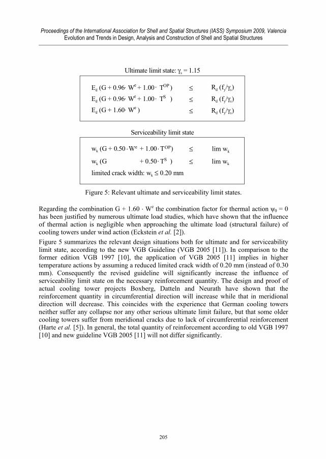
With regard to ultimate and serviceability requirements the actions dead load G, external wind We, operational temperature TOP and summer outage TS are significant to determine the reinforcement quantity. The consideration of these actions in equations (1) to (3) will achieve the relevant design situations of the ultimate limit state as shown in Figure 5. In case thermal actions are considered in a linear analysis, the stiffness reduction due to concrete cracking reduces the respective partial safety factor for actions T from γQ = 1.50 to γQ = 1.00 (Figure 5).
204
Proceedings of the International Association for Shell and Spatial Structures (IASS) Symposium 2009, Valencia Evolution and Trends in Design, Analysis and Construction of Shell and Spatial Structures
Ultimate limit state: γs = 1.15
≤ Rd (fy/γs)
Rd (fy/γs)
Rd (fy/γs)≤
≤
Ed (G + 0.96 W + 1.00 T )
Ed (G + 0.96 W + 1.00 T )
Ed (G + 1.60 W )
⋅
⋅
⋅
⋅
⋅
e
e
e
OP
S
S
Serviceability limit state
wk (G + 0.50 W + 1.00 T )
wk (G + 0.50 TS )
limited crack width: wk ≤ 0.20 mm
⋅
⋅
⋅
≤
≤e OP lim wk
lim wk
Figure 5: Relevant ultimate and serviceability limit states.
Regarding the combination G + 1.60 ⋅ We the combination factor for thermal action ψ0 = 0 has been justified by numerous ultimate load studies, which have shown that the influence of thermal action is negligible when approaching the ultimate load (structural failure) of cooling towers under wind action (Eckstein et al. [2]). Figure 5 summarizes the relevant design situations both for ultimate and for serviceability limit state, according to the new VGB Guideline (VGB 2005 [11]). In comparison to the former edition VGB 1997 [10], the application of VGB 2005 [11] implies in higher temperature actions by assuming a reduced limited crack width of 0.20 mm (instead of 0.30 mm). Consequently the revised guideline will significantly increase the influence of serviceability limit state on the necessary reinforcement quantity. The design and proof of actual cooling tower projects Boxberg, Datteln and Neurath have shown that the reinforcement quantity in circumferential direction will increase while that in meridional direction will decrease. This coincides with the experience that German cooling towers neither suffer any collapse nor any other serious ultimate limit failure, but that some older cooling towers suffer from meridional cracks due to lack of circumferential reinforcement (Harte et al. [5]). In general, the total quantity of reinforcement according to old VGB 1997 [10] and new guideline VGB 2005 [11] will not differ significantly.
205

Proceedings of the International Association for Shell and Spatial Structures (IASS) Symposium 2009, Valencia Evolution and Trends in Design, Analysis and Construction of Shell and Spatial Structures
ultimate limit state( ULS )
Ed (Fd) ≤ Rd
Rd = R (fcd, fyd) Rd = R (fcu, fyu) 1γR
material safety factorsγc = 1.50 ; γs = 1.15
fatigue strength: α = 0.85γR = 1.30 (1.10)
mean valuesfcm = α (fck + 8)fym ≈ fyk
⋅ ⋅design-valuesfcd = α fck / γc
fyd = fyk / γs
modified valuesfcR = γR / γc α fck
fyR = γR / γs fykftR = 1.08 fyR (ductile)
⋅⋅
⋅⋅
ultimate load design λu (fcR, fyR) ≥ γR
cross-section designE (fcm, fym) ≤ R (fcd, fyd)NL
Figure 6: Non-linear design procedure for ultimate limit state.
The structural analysis can be performed linearly or non-linearly using the method of finite elements. In case of linear design analyses in general a cross-section design shall be applied comparing the acting and resisting internal forces. Then the reinforcement quantity will be obtained directly. Using analyses including non-linear reinforced concrete models two different concepts are possible as shown in Figure 6 (Wittek and Meiswinkel [12]): A cross-section design according to EC 2 or an ultimate load design according to DIN 1045-1. The last will be explained in chapter 4. The contents of the new guideline VGB 2005 [11] refers to the current state-of-the-art in cooling tower design and construction, which is guaranteed by the experience of all members of the VGB panel of experts for “Structural Design of Cooling Towers”, particularly from the power plant operators, the construction industry and the engineering and research institutions (Lenz and Meiswinkel [7]).
4. Non-linear analysis methods The cross-section design with non-linearly calculated stress resultants ENL provides two different material laws – one with mean values fcm, fym for the calculation of internal forces and another one with design values fcd, fyd for the material capacities. Furthermore this concept underestimates the non-linear structural behaviour, as only the level of design load λ= 1.0 ≤ ultimate load factor λu is considered.
206

Proceedings of the International Association for Shell and Spatial Structures (IASS) Symposium 2009, Valencia Evolution and Trends in Design, Analysis and Construction of Shell and Spatial Structures
The alternative ultimate load design based on DIN 1045-1 (2001) provides a global safety factor γR = 1.30 for permanent and variable design situations respectively γR = 1.10 for accidental or seismic actions (see Table 2). The global safety factor γR, which represents the system resistance, is obtained for the cross-sectional safety considering the different material safety factors (Wittek and Meiswinkel [12]). To evaluate the ultimate state safety and to simulate the life-cycle behaviour of cooling towers, simulation of the crack-evolution in the shell is to be carried out early in the design phase (Harte et al. [3]). The following calculations were achieved by means of a doubly-curved, layered finite shell element, adopting a non-linear model for the material reinforced concrete, considering • non-linear bi-axial stress-strain relations for concrete in compression, • tension cracking after exceeding the concrete tensile strength, • elasto-plastic stress-strain behaviour of the reinforcement, • non-linear bond between reinforcement and concrete including tension-stiffening. The relevant load combinations under the main actions dead weight G, thermal loads T and wind W then are to be investigated by an incremental-iterative procedure by means of an amplification factor λ. The results of a cooling tower analysis applying the ultimate load design depend on the sequence of the different actions. According to VGB 2005 [11] the following load combinations need to be investigated λ (1.0/1.35 G + 1.50 T + 0.96 W) λ ≥ γR = 1.3, (5) λ (1.0/1.35 G + 1.60 W) λ ≥ γR = 1.3. (6)
The question arises, whether the dead weight is acting favourably or unfavourably. For most locations of the shell it will have a favourable effect, but this might deviate, for example in the vicinity of the duct inlet openings or in the lower ring-beam between the radial columns. As an example for a non-linear ultimate limit analysis, a case study of the 200m NDCT in Niederaußem has been performed in order to evaluate the relevance of the main actions contributing to the structural degradation (Wörmann [13]). Figure 7 shows the results for three different amplification variants, not including the partial safety factors for actions.
207

Proceedings of the International Association for Shell and Spatial Structures (IASS) Symposium 2009, Valencia Evolution and Trends in Design, Analysis and Construction of Shell and Spatial Structures
λ (G + T + W)
0.0
Load
fact
or λ
[-]
Normal displacement v3 [m]
0.4
0.8
1.2
1.6
2.0
2.4
2.8
0.00 -0.15 -0.30 -0.45 -0.60 -0.75 -0.90 -1.05 -1.20
G + λ (T + W)
A
λ = 2.50
λ = 2.06
λ = 2.14
G + T + λW
Figure 7: Non-linear load-deflection-diagram at point A of NDCT Niederaußem for different amplification variants.
It can be recognized that the joint amplification of all actions λ (G + T + W) will result in an overestimation of the structural capacity. This is because the permanent action G is acting favourably. No difference with respect to ultimate limit design will occur, when either both T and W or only W are amplified by λ. The resulting ultimate load factors are close to the required value λ ≥ 1.3 ⋅ 1.6 = 2.08, thus demonstrating the economic design of the Niederaußem tower. Differences occur on the level of serviceability loads, where the consideration of amplified thermal actions, which as well represent additional hygric effects, results in larger displacements and greater crack widths. Thus the amplification of both T and W seems to be the most realistic variant, subsequently first the thermal, then the wind action: G + λ1 T + λ2 W (Wörmann [13]).
5. Construction of cooling towers Except the Datteln cooling tower all other NDCTs shown in Figure 1 are founded on continuous concrete ring beams, interrupted by a massive underground building for the water inlet and outlet. In general, the foundation is modelled by shell elements, which are continuously bedded by the corresponding elastic soil-stiffness provided by the soil-expert. In case of difficult or inhomogeneous soil situation the consideration of soil-structure-interaction by means of a finite-infinite-element model could be advantageous (Harte and Mahran [6]). The Datteln cooling tower is founded on a pile foundation below the ring beam, consisting of prefabricated concrete piles driven into the soil. The support system, today mostly designed as radial supports and not as A-, V- or X-columns (Figure 8), is prefabricated in case of NDCTs in Niederaußem, Neurath and Hamm, but concreted in-situ in case of NDCTs in Boxberg and Datteln.
208

Proceedings of the International Association for Shell and Spatial Structures (IASS) Symposium 2009, Valencia Evolution and Trends in Design, Analysis and Construction of Shell and Spatial Structures
Figure 8: Support system: A-, V-, X-columns or radial supports (System: Heitkamp).
The shell itself is erected in the classical way, by means of a climbing formwork with 1 to 1.5 m climbing steps. High quality in shape is guaranteed by continuous laser-based measuring means during the climbing process. Further improvement of the long-term durability can be achieved, if the upper ring beam is pre-stressed and thus concrete cracking due to severe wind action is prevented (Montag et al. [8]).
Acknowledgement The support of the presented projects by the power suppliers E.ON, RWE, Vattenfall, by the cooling technology contractors GEA, HAMON, SPX, by the construction companies Alpine, Heitkamp, Hochtief and Wayss & Freytag, and by VGB PowerTech is gratefully acknowledged.
References [1] Busch D., Design and construction of cooling tower at the Niederaussem power plant,
unit K, VGB PowerTech 3/2001, 91-95. [2] Eckstein U., Krätzig W.B., Meiswinkel R. and Wittek U., Anwendung nichtlinearer
Tragwerksanalysen für die Umrüstung bestehender Kühltürme, Bauingenieur 72, 1997, 263-269.
209

Proceedings of the International Association for Shell and Spatial Structures (IASS) Symposium 2009, Valencia Evolution and Trends in Design, Analysis and Construction of Shell and Spatial Structures
[3] Harte R., Krätzig W.B., Noh S.-Y. and Petryna Y.S., On progressive damage phenomena of structures, Computational Mechanics 25, 2000, 404-412.
[4] Harte R. and Krätzig W.B., Large-scale cooling towers as part of an efficient and cleaner energy generating technology, Thin-Walled Structures 40, 2002, 651-664
[5] Harte, R., Krätzig, W.B., Montag, U. and Petryna, Y.S., Damage, rehabilitation and residual life duration of natural draft cooling towers, VGB PowerTech 6/2005, 61-66.
[6] Harte R. and Mahran E., Numerical simulation of soil-structure-interaction of towers and tanks via finite and infinite elements, Papadrakakis M & Topping BHV (eds.) Proc. 6th International Conference on Engineering Computational Technology, Athens, Greece, September 2-5, 2008.
[7] Lenz J. and Meiswinkel R., The revised German VGB Guideline “structural design of cooling towers” – adjustment to the new generation of European standards, Mungan I & Wittek U (eds.), 5th International Symposium on Natural Draught Cooling Towers, Istanbul, Turkey, May 20-22, 2004, 249 - 255.
[8] Montag U., Busch D., Harte R. and Krätzig W.B., The 200m Nierderaussem tower – design and static approach, Mungan I & Wittek U (eds.), 5th International Symposium on Natural Draught Cooling Towers, Istanbul, Turkey, May 20-22, 2004, 189-199.
[9] Niemann H.-J., Hölscher N. & Höffer R., Consideration of directional wind effects in the design of cooling towers, Zingoni A (ed.) Proc. 3rd International Conference on Structural Engineering, Mechanics and Computation SEMC2007, Cape Town, South Africa, September 10-12, 2007.
[10] VGB 1997, BTR-Guideline: Structural Design of Cooling Tower, VGB-Technical Association of Large Power Plant Operators, VGB-R 610Ue, Essen, Translation of German edition 1997.
[11] VGB 2005, BTR-Guideline. Structural Design of Cooling Towers, VGB PowerTech e.V. Technical Association of Large Power Plant Operators, VGB-R 610Ue, Essen, Translation of German edition 2005.
[12] Wittek U. and Meiswinkel R., Structural safety requirements for the ultimate load design of RC plates and shells, Proc. 4th International Symposium on Computation of Shells and Spatial Structures IASS-IACM, Chania-Crete, Greece, June 4-7, 2000.
[13] Wörmann R., Zur Erfassung hygrothermischer Einflüsse auf das nichtlineare Trag- und Schädigungsverhalten von Stahlbetonflächentragwerken, Institut für Konstruktiven Ingenieurbau, Heft 2, Bergische Universität Wuppertal, 2004.
210