reeves, james willard, 1931- nonlinear analysis of...
TRANSCRIPT

NONLINEAR ANALYSIS OFAXISYMMETRIC CIRCULAR PLATES
Item Type text; Dissertation-Reproduction (electronic)
Authors Reeves, James Willard, 1931-
Publisher The University of Arizona.
Rights Copyright © is held by the author. Digital access to this materialis made possible by the University Libraries, University of Arizona.Further transmission, reproduction or presentation (such aspublic display or performance) of protected items is prohibitedexcept with permission of the author.
Download date 10/06/2018 02:29:13
Link to Item http://hdl.handle.net/10150/287442

This dissertation has been microfilmed exactly as received 70-8026
REEVES, James Willard, 1931-NONLINEAR ANALYSIS OF AXISYMMETRIC CIRCULAR PLATES.
University of Arizona, Ph.D., 1970 Engineering, civil
University Microfilms, Inc., Ann Arbor, Michigan

NONLINEAR ANALYSIS OP AXISYMMETRIC CIRCULAR PLATES
by
James Wlllard Reeves
A Dissertation Submitted to the Faculty of the
DEPARTMENT OF CIVIL ENGINEERING
In Partial Fulfillment of the Requirements For the Degree of
DOCTOR OF PHILOSOPHY
In the Graduate College
THE UNIVERSITY OF ARIZONA
1 9 7 0

THE UNIVERSITY OF ARIZONA.
GRADUATE COLLEGE
I hereby recommend that this dissertation prepared under my
direction by Jamas Wi I lard Reeves
entitled Nonlinear Analysis of Axisymmetric
Circular Plates
be accepted as fulfilling the dissertation requirement of the
degree of Doctor of Philosophy
ho an Director Date /J f ' tation
After inspection of the final copy of the dissertation, the
following members of the Final Examination Committee concur in
its approval and recommend its acceptance:"
/r, tff
T" ts, !%<f
Aug. I5} acq
ft This approval and acceptance is contingent on the candidate's adequate performance and defense of this dissertation at the final oral examination. The inclusion of this sheet bound into the library copy of the dissertation is evidence of satisfactory performance at the final examination.

STATEMENT BY AUTHOR
This dissertation has "been submitted in partial fulfillment of requirements for an advanced degree at The University of Arizona and is deposited in the University Library to be made available to borrowers under rules of the Library.
Brief quotations from this dissertation are allowable without special permission, provided that accurate acknowledgment of source is made. Requests for permission for extended quotation from or reproduction of this manuscript in whole or in part may be granted by the head of the major department or the Dean of the Graduate College when in his judgment the proposed use of the material is in the interests of scholarship. In all other instances, however, permission must be obtained from the author.
SIGNED

AC KNOWLEDGMENTS
The author is indebted to Dr. Ralph M. Richard,
director of this dissertation, whose guidance, and initial
conception of the merits of the problem., led to the
completion of this investigation.
Appreciation is extended to all of the Civil
Engineering faculty members and to the author's colleagues,
whose instruction, association, and assistance ultimately
have made this dissertation possible. In particular,
sincere thanks are expressed to Wilbur D. Birchler and
Melvin L. Callabresi for many rewarding discussions pertain
ing to this study.
I am indebted to the National Science Foundation
and to the University of Southwestern Louisiana for
financial support during my graduate program.
The encouragement, support, and unfailing confidence
of my parents, Leon and Julia Reeves, are acknowledged and
deeply'appreciated.
As a token of my deepest gratitude for their love,
patience, and understanding, I proudly dedicate this dis
sertation to my wife, Clara, and rny children Tracy and
Christine.
iii

TABLE OP CONTENTS
Page
LIST OP ILLUSTRATIONS vl
LIST OP SYMBOLS ix
ABSTRACT xii
1. INTRODUCTION I
Problem Statement 1 Review of Literature . . • 4
2. FORMULATION OP EQUATIONS 12
Nonlinear Plate Equations 12 Equilibrium 12 S t r e s s - S t r a i n . . . . . . . . . . . . . . 1 6 Moment-Deflection 18
3. METHOD OP SOLUTION 22
Introduction 22 Matrix Formulation 22 Element Stiffness Matrix 24
Linear Analysis 24 Nonlinear Analysis 29
Applied Loads 31 Constitutive Relationship 32 Cap Element 37 Mechanics of Solution 40
4. APPLICATIONS AND EXAMPLES 46
Introduction 46 Linearly Elastic Material ' 46
Edge Loaded—Simply Supported Annular Plate 47
Uniformly Loaded—Simply Supported Plate. 50 Nonlinear Material . 52
Uniformly Loaded—Clamped Plate 52 Concentrated Load—Simply Supported
Plate No. 1 ....... 55 Concentrated Load—Simply Supported Plate
No. 2 66
iv

V
TABLE OF CONTENTS—Continued
Page
5. SUMMARY AND CONCLUSIONS 80
REFERENCES . 82

LIST OF ILLUSTRATIONS
Figure Page
1-1. Description of Discrete Model 8
2-1. Infinitesimal Element of a Circular Plate . 13
2-2. Projection of an Infinitesimal Element on the r-z Plane . 14
3-1. Plate Element showing Generalized Displacements and Forces 27
3-2. Nondimensional Stress-Strain Relationships . 33
3-3* Nonlinear Parameter n 34
3-4. Nondimensional Secant Modulus 36
3-5. Circular Cap Element 38
4-1. Results for Inner Edge of an Annular Plate . 48
4-2. Annular Plate Results—Single Load 49
4-3- Results for a Uniformly Loaded, Simply Supported Plate 51
4-4. Load-Deflection Curve for a Uniformly Loaded, Clamped Plate .... 53
4-5. Radial Stresses 56
4-6. Plate Model showing Nodal Circles 57
4-7. Radial Slopes 57
4-8. Lateral Displacement Profiles 58
4-9. In-Plane Displacement Profiles 58
4-10. Membrane Forces 59
4-11. Bending Moments ........ 59
vi

vii
LIST OP ILLUSTRATIONS--Continued
Figure Page
4-12. Top Surface Radial Stresses 60
4-13- Top Surface Circumferential Stresses ... 60
4-l4. Bottom Surface Radial Stresses 61
4-15. Bottom Surface Circumferential Stresses . . 61
4-16. Radial Stress Distribution through the Plate Thickness 62
4-17- Circumferential Stress Distribution through the Plate Thickness 63
4-18. Load-Deflection Curve for a Simply Supported Plate with a Concentrated Load—No .1 64
4-19. Lateral Displacement Profiles— Concentrated Load 67
4-20. Radial Slopes—Concentrated Load 67
4-21. Top Surface Radial Strain over the Support . 68
4-22. Top Surface Circumferential Strain over the Support 68
4-23. Top Surface Circumferential Strain at Station •§• Inch away from Support ... 69
4-24. Top Surface Radial Strain at Station Inch away from Support ... 69
4-25. Top Surface Radial Stress— Concentrated Load 70
4-26. Bottom Surface Radial Stress— Concentrated Load 71
4-27. Top Surface Circumferential Stress— Concentrated Load 72
4-28. Bottom Surface Circumferential Stress— Concentrated Load 73

LIST OP ILLUSTRATIONS—Continued
viii
Figure * Page
4-29- Stress Distribution through the Plate Thickness—Concentrated Load 74
4-30. Load-Deflection Curves for a Simply-Supported Plate with a Concentrated Load—No. 2 ~. . . 76
4-31. Results for a Concentrated Load of 20 lbs 77
4-32. Results for a Concentrated Load of 500- lbs. 78

LIST OP SYMBOLS
Symbol Definition
A equilibrium matrix
a outer radius of the plate
B compatibility matrix
b inner radius of the plate
f1 v2 I . 5- dz - flexural rigidity of the J - 75- 1-u- plate
•cn-,3 D1 ———5— — flexural rigidity of the plate
12 (1-u )
d matrix of nodal displacements
d differentiation with respect to the radial cEr coordinate, r
E . modulus of elasticity of plate material
Es seoant modulus of elasticity
e_ radial normal strain r
e^. circumferential normal strain
f vector of applied forces
h
H P Es
H- _a» _ (i-u2)
ix

plate thickness
initial "boundary of* finite element
final boundary of finite element
B^kB = system oriented stiffness matrix
element stiffness matrix
radial bending moment per unit length
circumferential "bending moment per unit length
radial membrane force per unit length
circumferential membrane force per unit length
nonlinear stress-strain parameter
applied concentrated load
vector of internal forces
shearing force per unit length
intensity of uniform load
/ h A i d z ' " 2"
Poisson's ratio I
membrane radial displacement
normal displacement
coordinate directions
^ = rotation
radius of curvature in the radial direction

xi
radius of curvature in the circumferential direction
effective von Mises stress
uniaxial yield stress of the material
radial normal stress *
radial bending normal stress
radial membrane normal stress
circumferential normal stress
circumferential bending normal stress
circumferential membrane normal stress

ABSTRACT
An annular plate element is presented for analyzing
structural, axisymmetrical, initially flat, circular plates
subject to finite deflections and having nonlinear material
properties. The displacement method of matrix structural
analysis is used.
The element stiffness matrix is formed by utilizing
the differential equations for the annular element. The
equations are integrated across the element. To account
for finite deflections, the equations are uncoupled by
separating membrane and bending effects.
A cap element is used to circumvent the singularity
which exists at the center of the plate. This allows a
solid plate to be simulated and permits the application of
a concentrated load at the center of the plate.
The total load is first applied to the plate in one
step. Using the linearly elastic, small deflection solution
as an initial estimate, an iterative technique is employed
to arrive at the final solution.
The Richard equation is used to account for work
hardening of the material. The effective stress is cal
culated using the von Mises yield criterion, and then is
used in the Richard equation to obtain the secant modulus
xii

xiii
of elasticity. This modulus is determined at discrete
points through the thickness of the plate at the centroid
of each element.
Several numerical examples are given to illustrate
the accuracy of the method.

CHAPTER 1
INTRODUCTION
Problem Statement m
The classical theory of plates which assumes small
deflections is noticeably deficient in describing the
behavior of thin plates. When lateral deflections exceed
one-half of the plate thickness,, the prediction of stresses
and displacements by the classical theory is erroneous
(Timoshenko and Woinowsky-Krieger, 1959)* Since many plates
remain useful for deflections far in excess of this,.a more
general theory is needed.
Von Karman in 1910 presented the fundamental theory
for the analysis of elastic plates with large deflections
(Timoshenko and Woinowsky-Krieger, 1959)• These equations
are nonlinear and include the effects of membrane forces and
the second order effects of lateral displacements in the
associated strain-displacement equations. The solution of
these equations in the general case is unknown.
Large deflections, as used in this paper, mean
deflections which are of the same order as the plate thick
ness, yet which are small compared to the other plate
dimensions. In studying the case of large deflections,
combined action of membrane stretching and bending must be
X

2
considered. The equations of equilibrium would relate to
an element of the plate in the deflected position and not
to an element of the initially flat plate. Since this
distorted shape is not known beforehand, but is part of the
required solution, nonlinear!ty is introduced. Even for
Hookean material the problem yields a solution which is not
linear in that deflections and stresses are not proportional
to applied loads.
The problem is further complicated if yielding of
the material is included. Attempts to include large deflec
tions and yielding of the material have generally been
restricted to specialized stress-strain relations such as
rigid-plastic material (Onat and Haythornwaite, 1956$ Cooper
and Shifrin, 195*0 and elastic-perfectly plastic material
(Crose, 1967)•
In certain design problems, such as aerospace
structures, plastic deformation may be tolerated in order
to utilize the materials more efficiently. In fact, plastic
deformation may have the beneficial effect of alleviating
the stress concentrations.
The treatment of problems of large deflections with
full generality represents a task which is at this time
outside the realm of mathematical tools. The availability
of the digital computer, the techniques of finite element,
and a tractable constitutive relationship now make the

3
numerical solution for nonlinear geometry and nonlinear
material possible for special problems.
In this paper the circular plate is divided into a
number of annular rings, called plate elements. The edges
of the rings where the elements are connected are called
nodal circles. Because each element may be considered as a
separate unit, different material properties, thicknesses,
and loadings can be ascribed to the individual elements.
The direct stiffness method is used to establish a
force-displacement relationship between the nodal circle
forces and moments and the corresponding displacements and
rotations. *
Birchler, Callabresi, and Murray (1968) derived the
element stiffness matrix for a linearly elastic annular
element subject to small deflection by integrating the
governing differential equations. A searching.procedure
was used to convert the boundary value problem to an initial
value problem. This same procedure is used here after the
nonlinear plate equations are stepwise linearized.
An Iterative technique is used to handle the
geometric nonlinear!ty. Holding certain terms constant
from the previous iteration and uncoupling the membrane and
bending effects results in a linearization of the nonlinear
governing differential equations. Utilizing the linear,
small deflection solution as an initial estimate of the

4
deflected shape, iteration is continued until the solution
converges within a given desired tolerance.
A constitutive relationship developed by Richard
(1961) is used to solve the material nonlinearity (Goldberg
and Richard, 1963)• This relationship gives the stress as
an explicit function of strain and ensures a smooth transi
tion from elastic action to plastic action. The degree of
nonlinearity may be adjusted by varying the three parameters
in the Richard equation. Yielding of the material is
governed by the von Mises yield criterion. '
The material respons.e of the element is assumed to
be governed by the variation of effective stress through the
plate thickness at the center of the element. The plate
thickness is divided into a number of layers. The secant
modulus is evaluated at the interface of each layer and at
the upper and lower faces of the plate. These secant moduli
are held constant during each iteration.
Review of Literature
Solutions for moderately large deflections of thin
plates are based on the equations formulated by von Karman.
Numerous authors have presented methods of treating these
nonlinear equations for axially symmetric circular plates.
Way (1934) presents a series solution for uniformly
loaded, elastic circular plates. This results in an "exact"
solution of the differential equations. The differential

5
equations are first written in dimensionless form. Since
the radial membrane stress is a symmetrical function of the
radius, r, this stress can be expanded in a series of even
powers of r, and since the slope Is an antisymmetrical
function of r, it can be expanded in a series of odd powers
of r. These series in dimensionless form are as follows:
= BQ + BgX2 + B^x^ + ...
=VfT(C1x + + C^x^ + )
where x = r/h. Substituting these two relationships into
the governing differential equations results in recurrence
formulas for and Ck. The general solution is now known.
The particular solution results from application of the
boundary conditions. $
The author considers two cases: (1) plates with no
load, with a moment at the edge, and zero tensile force at
the edge; and (2) plates with a uniform load, clamped edge,
and zero radial edge displacement. Central lateral deflec
tions and stresses are presented for deflections up to
approximately 1.2 times the plate thickness. In attempting
to extend this method to larger deflections, it was found
that convergence was very difficult to obtain. This same
problem confronted McPherson, Ramberg, and Levy (19^2) when
they attempted to extend Way's method.

6
Wempner and Schmidt (1958) present a series
solution of the von Karman equations for elastic, annular
plates, a case for which Way's solution is not applicable.
The method is very similar to Way's method. Series
solutions are assumed for the radial membrane force and
the radial slope. Two recurrence formulas for "the series
coefficients result from substituting the series into the
differential equations. All coefficients are determined in
terms of four arbitrary constants. For the case of un
restrained radial movement and rotation at the edges
discussed in this paper, two of the arbitrary constants are
eliminated. A numerical solution is accomplished by
estimating and successively correcting the other two'
arbitrary constants until the boundary conditions are satis
fied to a desired degree of accuracy. Although the only
case discussed is an annular plate with unrestrained radial
movement and rotation at the edges, the authors state that
the method is equally applicable to other edge conditions
and other load conditions. A method for demonstrating
convergence and appraising the error is included. Conver
gence of the series is dependent on the magnitude of the
ratios of trie inner radius to the outer radius, the plate
thickness to the outer radius, and on the load. In partic
ular, small values of plate thickness to outer radius can
result in extremely slow convergence. In fact, there is no
assurance that the series will converge for all values of

7
these parameters. Results are presented for deflections up
to approximately 1.4 times the plate thickness. Although
no statement is made in this regard, possibly the method
also has the same convergence problem that occurs in Way's
method when the deflection to thickness ratio exceeds the
range presented.
Several investigators have analyzed plates with
large deflections which do not remain elastic. In all
cases bilinear stress-strain relationships were assumed.
Crose (1967) presents a method for analyzing
nonlinear circular plates which is based on a physical
discretization of the continuum. The models shown in
Figure 1-1, is a lumped parameter model interconnected by
axial and shear springs. It is essentially a physical
analog of the finite difference equations for the continu
ous plate. The total mass of the solid continuum is
concentrated at the mass points. The procedure is further
simplified by adopting a sandwich configuration. The plate
consists of three layers. The top and bottom layers,
containing all of the mass, are identical and are assumed
to be characterized by a uniform plane stress distribution
across the thickness. Separating these two sheets is a
shear core of constant thickness which is infinitely stiff
with respect to transverse shearing forces, and which
provides no reslstence to flexural and extensional forces.
The idealization of the solid plate to a sandwich plate

(a) Plan View
•W A/WV O
•' "O" •VSAAr Unde formed Position Deformed Position
(b) Elevation View
Figure 1-1. Description of Discrete Model

9
simplifies the problem by eliminating the effect of
yielding through the thickness.
The material in the top and bottom sheets is
assumed to be elastic-perfectly plastic. Yielding is
governed by the von Mises criterion and plastic flow
follows the Prandtl-Reuss flow rule. The author states
that the approach is equally applicable for other inelastic
materials.
The stress-strain equations must be in incremental
form because of the use of the incremental theory of
plasticityj therefore the remainder of the field equations
are converted to incremental form. Load is applied in
increments3 and an iterative technique is utilized. The
linear elastic solution results from the first iteration.
Within each iteration, the linear equations are solved by a
modified Gauss elimination scheme. Load is applied in
small increments until a desired level of loading is
achieved. The efficiency of solution depends on the mag
nitude of the load increments.
The main restriction on the load increment is made
during plastic flow. If the increment is too large, the
yield criterion will be seriously violated. When this
happens, the load increment is decreased by interpolation
and a smaller increment of load applied. The magnitude of
the load increment is also limited during plastic flow by
certain stability requirements of the nonlinear equations

10
and by certain assumptions made regarding transformation
of displacements.
The primary advantage realized in using the discrete
element formulation is that the resulting equations can be
derived through the use of elementary mechanics and simple
geometry. Also, the equations are physically meaningful
when related to the model.
Three specific problems are presented and discussed.
Two of these are clamped plates with uniformly distributed
lateral loads, and one is a simply supported plate with a
concentrated load at the center.
Naghdi (1952) used the theory of plastic deformation
from the theory of plasticity to develop a method of'
handling strain-hardening materials. The equilibrium
equations are written to include the effects of large
deflections. The amount of strain hardening is related to
the octahedral shear strain and the plate rigidities and
material moduli are adjusted accordingly. Using a tensile
stress-strain curve, an octahedral shear stress-shear
strain curve is constructed according to a procedure which
Naghdi states has been verified experimentally. Various
parameters are then plotted versus octahedral shear strain,
and the variation of the octahedral shear strain is
determined through the thickness of the plate.
An iterative procedure is used. To simulate a
closed plate, a small rigid plug.is assumed to be inserted

11
at the center of the plate. Once fair results are obtained,
the plug is removed and computations are carried out for
several more cycles. Numerical solutions for two load
cases are presented for a simply supported circular plate
with a central concentrated load. Tests were conducted to
verify the analytical results and good agreement was found
for deflections.
Onat and Haythornwaite (1956) combine the solution
for flat plates due to Hopkins and Prager (1953) and the
Tresca yield criterion to develop an analysis for large
deflections of circular plates composed of rigid plastic,
nonstrain-hardening material. Their analysis is compared
to the results from two plate tests and is found to give
poor agreement with the tests.

CHAPTER 2
FORMULATION OF EQUATIONS
Nonlinear Plate Equations m
Equilibrium
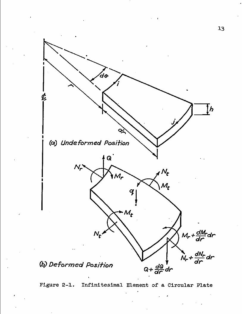
Figure 2-1 shows an infinitesimal element of a
circular plate in its undeformed state and in its deformed
state including loads and forces. Since the displacements
may be large, the equations of equilibrium must be satis
fied in its deformed position (Novozhilov, 1953)-
Figure 2-2 shows*the projection of the deformed
shape on the r-z plane. The load, q, and the forces,
M.J., Nr, N^. and Q, are the forces acting on the element.
The displacement functions v and w determine the deformed
shape of the plate and as such determine the radius of
curvature pr.
Summation of forces in the radial direction, r, for
the element in its deformed state yields
dN Nr(rd0) cos -gp + Ntdrd0 - (Nr + dr)(r + dr)
d© cos dr) = 0 (2-1) ar dr
12
13
9<S
(oQ Uncle formed Position
• Q
Mr+^-rdr r dr
(b) Deformed Position
V
Figure 2-1. Infinitesimal Element of a Circular Plate

14
W
dw/dr\
dr
Figure 2-2. Projection of an Infinitesimal Element on the r-z Plane

15
Expanding the last term in Equation (2-1) gives
dN Nr(rd0) cos + Ntdrd6 - (Nr + dr)(r + dr)
d0(cos cos dr - sin 5^ sin ^ dr) = 0 (2-2) dr dr
By taking the cosines of small angles equal to one and the
sines of small angles equal to the angles this equation
becomes
dN Nrrd9 + Wtdrd9 - (Nr + dr) (r + dr)
de(l - dr) =0 (2-3) dr
Summation of forces in the z direction yields
QrdS + nrrde - (Q + §§ dr) (r + dr)d©
- (Nr + dr)(r + dr)de(|2 + dr)
- qrdrd© = 0 (2-4)
Summation of moments in the r-z plane yields
dM, M^d© - (Mr + dr)(r + dr) d0 + M^drd0
+ Qrdrd0 = 0 (2-5)

16
Dividing "by drd© and neglecting higher order terms,
Equations (2-3), (2-4), and (2-5) become, respectively,
These are the final equilibrium equations for the plate.
The last term in Equation (2-6) results from expanding the
cosine term in Equation (2-1). This term is retained
because it is not a higher order term, and because it may
become large where a plate has a large membrane force and
large curvature.
Stress-Strain
For an elastic, isotropic material with plane stress
conditions, the stress-strain relationship is described by
Hooke's Law. These equations in polar coordinates are
dW ^ - Kt + wr (2-6)
Q + r^ + rNrg» + I^^£ + Nr^ + qr = 0 (a-7)
dM. M r + r ^ - M t - Q r = 0 (2-8)
(2-9)

17
In large deflection analysis* the middle plane stretching
is included, therefore the membrane strains must be included, *
These strains are (Timoshenko and Woinowsky-Kriegerj 1959)
e - dv + .Lydw\g r» r}y 2 V HW 'r dr- 2Vdrj
(2-10)
e. = t r
5y definition
Nr=/| £
h 2" o;dz
(2-11) h
"S-wt=/; h °^dz
Substituting Equations (2-9) and (2-10) into Equation (2-11)
results in
N r = [ £ + i ( ! £ ) 2+ ^ ] H
(2-12)
r ~3r~ T 2 cir'' 1 " n, = t i + ) H
where h
K = f ^ Es dz
7- h

18 In Equations (2-12) the modulus of elasticity* E3 has been
replaced by the secant modulust E . because nonlinear
material is considered in this study. The method of
evaluating E_ will be explained in Chapter 3>
Moment-Defleetion
The definitions of radial and circumferential
moments are
The Kirchhoff-Love hypothesis* which states that for thin
plates a normal to the middle surface remains normal during
deflection, allows the bending strains to be expressed as
er = z:/ Pr and e^ = z/ Equations (2-9) can therefore
be expressed as
h
(2-13)
h
(2-14)

19
The curvatures are defined as (Timoshenko and Woinkowsky-
Krieger, 1959)
_1_ = -d2w
Pr dr2
(2-15)
1 _ 1 dw pt 'r w
Substituting Equations (2-14) and (2-15) into Equation
(2-13) gives
^ [ gw + « g ]
(2-16) vi - i-i r 1 dw . „ d w i
where
h 2 r t v D =/ d -2-rr dz / h l-u^
Again E has replaced E.
The plate rotation, dw/dr, is also expressed as .
Equations (2-6), (2-7), (2-8), (2-12), and (2-16) are com
bined to form six first order, ordinary, nonlinear differen
tial equations as follows:

20
Hr = P C0"1?)
N o 5 v = _Z HZ fo ifti dr H atdr; ~ (2-lts)
d/3 _ Mr u/6 lqv "Sr D r~ (2-19)
- a - . a + v ^ . M ( 1 . u ) dr r D r ^ '
Ax v N„ N A* UN A -f* (1-u) [ X(1+U) - -jf ] + r l/0 + —e£
2 „3 (2-20) c iitvt /1~>
dNr _ H(l-u) r V/-, , v Nr , WrMr/^ uWr/3 (2-21)
« L V. k J-"™-; H J ri ~
- q
dr r L rv ' H J D
= -D(l-u) t A (1+u) + ] + Q (a_22)
These six equations will be used to solve for •
the' , forces, Q3 NrJ and MrJ and the displacements,
Wj Vj and /3. After these forces and displacements
have been found, the circumferential force and moment may
be found by using Equations (2-12) and (2-16). By utilizing
Equations (2-17)» (2-18),, and (2-19), and noting that
d^w _ d/?
dr2 dr

21
Equations (2-12) and (2-16) may be expressed as
+ UN3
Mj. = - .(1-u2) + uMj.
(2-23)

CHAPTER 3
METHOD OP SOLUTION
Introduction m
Structural systems which "behave elastically can be
analyzed by either the displacement method or the force
method. The same methods can be used for nonlinear systems
as presented by Richard and Goldberg (1965) and Goldberg
and Richard (1963). Because of the ease of generating the
required equations on the digital computer, the displacement
method is used here. • -
Matrix Formulation
The matrix formulation of the displacement method
is based on the equilibrium, stress-strain, and compati
bility relationships of a deformable body. From
equilibrium considerations, the vector of applied forces,
f, is related to the vector of internal forces, p, "as
f = Ap (3-1)
where A is known as the equilibrium matrix. Using the
stress-strain relationship, the internal forces, p, are
determined in terms of the internal deformation, v, as
p = kv- (3-2)
22

23
inhere k is called the stress-strain matrix, or the element
stiffness matrix. Maintaining continuity results in the
expression relating external deformationss d, to the internal
deformationsj Vj
v = Bd (3-3)
where B is known as the compatibility matrix. It can be
shown from the theorem of virtual work that the compati
bility matrix is the transpose of the equilibrium matrix.
Combining the above equations results in
or
or
where
also
The displaced configuration for any applied loading can be
found from the set of simultaneous algebraic equations
represented by Equation (3-4).
f = AkBd (3-4a)
f = BtkBd . (3-4b)
f = Kd (3-^c)
K '= BtkB
p = kBd (3-5)

24
Element Stiffness Matrix
Linear Analysis
Birchler, Callabresi, and Murray (1968) demonstrated
the feasibility of deriving the element stiffness for an
elastic annular element for small deflections by using the
governing differential equations. Because a similar
procedure is used for the nonlinear analysis, a review of
the procedure is presented here for convenience.
Using the infinitesimal element of a circular plate
in its undeformed state, as shown in Figure 2-1, and
assuming small deflections, the equilibrium equations
analogous to Equations (2-6), (2-7)9 and (2-8) are (Timo-
shenko and Woinowsky-Krieger, 1959)
Hr + r ££ " Nt - 0
Q + r^| + qr = ° (3-6)
dM» + r - Mt - Qr - 0
The stress-strain relationship analogous to Equations (2-11) t
is
Nr = H' [ + u 2 ]
Nt = H' I? + u3? 1
(3-7)
where H1 - 3 l-u

25
The moment-deflection relationship analogous to Equations
(2-15) is
^ = "D' + 1 dr
2 w • _ n i r l d w J . « d w i = " D t r ¥ + u ^ ]
(3-8)
•cn-,3 where D' = ——
12(l-u2)
The rotation, /3 s of the plate is expressed as a function
of the displacement w "by the equation
A - dw P ~ ~Sr
The above equations are combined to form six first
orderA ordinary, linear differential equations as follows:
N dv r uv "3? H1 r
_ Vi/3 dr r T51"
= _ £ _ q dr r H
dNr _ H'(1-u2)v wr(1_u)
" > ~
dMr _ D' (1-u2) & M1-*) -ar ^5-^ r +
(3-9)
<Z

26
After solving these equations at discrete points along the
plate, the values of and Mt can "be found at each point
from the equations
= h,(1;"2)V + un t r r
(3-10) « _ _ P' + t r _ r
By definition each column of the element stiffness
matrix is a generalized force vector which deforms the
element in accordance with the differential equations., omit
ting applied loads, so that all the generalized displace
ments are zero except for the unit displacement associated
with that column. Based on this definition, a procedure
to determine the element stiffness matrix is developed.
The undeformed plate element, Figure 3-1* has six
generalized displacements and six associated generalized
forces, three of each at each "boundary in the radial direc
tion. If all six of the initial conditions at node i are
known, the six first order governing differential equations,
Equations (3-9)* can "be solved by a fourth order Runge-
Kutta numerical integrating procedure. Prom the unit
displacement method where all displacements are zero except
one which is unity, three initial and three final general
ized displacements are known. This means that three initial
conditions, the generalized forces Nr^, and Mr^, are
unknown; and they must be the particular values to insure

27
Wi Wt
Vi
•e 'ft
•~-r
(a) Generalized Displacements
Q, Mri
•
' / J
Q;
Mrj
•*~r
(b) Generalized Forces
Figure 3-1* Plate Element showing Generalized Displacements' and Forces

28
the known values of the final displacements in accordance
with the governing differential equations.
A searching procedure is used to find these initial
forces. Using a set of assumed initial forces (Q^°^ ^ri^
and "the differential equations are solved by numerical
integration to give a set of final end displacements
v(°>, and By incrementing the initial forces and
re-solving for the final displacements, the change in final
displacements due to unit force changes can be determined.
These results may be written as
<P/3j
3% ' S>e± * <9
<5>W1 5vJ o>"ri d "ri '
9/5s
SMri ' o>Mri ' olMri
(3-11)
where the ratios represent partial derivatives. By applying
the chain rule of differential calculus, the following matrix
relationship is obtained.
Awj1 aWj
f * A^ Awj1
d 9 Nri a
f * A^
Avj • =
3 v 1
d<i± •
3 Nri
3 vj o>Mri
< Auri ,
A/Sj
* 3 \ 3Mri
*fi3 3Mri J A^
(3-12)

29
The quantities Aw^, and A/0j are the changes
required in "Wj0^ VJ°^ and sive known final
end displacements. Solving, Equations (3-12) for the quan
tities AQ^ AN and AMr^ and then adding them to
Nri^ an(* Mri^ respectively will yield a set of initial
forces that corresponds to the known final end displace
ments. The differential equations are re-solved using the
proper set of initial conditions to obtain the final forces
These final forces Qj, rj3 and ^r.j* al°nS with the initial
forces ^ri3 and Mri* ^orm a column of the element
stiffness matrix. The above procedure is repeated for the
six sets of the generalized displacements, thus generating
the complete 6x6 stiffness matrix for one element.
Nonlinear Analysis
The above procedure for forming the element stiff
ness matrix is applicable when the governing equations are
linear. For the case of large deflections, the equations
are nonlinear and must be linearized before the element
stiffness matrix can be formed. To accomplish this*, the
equations associated with bending, Equations (2-17)/ (2-19)
(2-20), and (2-22), are separated from the equations associ
ated with stretching of the membrane, Equations (2-18) and
(2-21). All bending terms in membrane equations and all
membrane terms in the bending equations are held constant
for each iteration. The secant modulus, Eg, and therefore

30
H and Da is also held constant for each iteration.
The bending equations become
(3-13)
a/3 = _ ^ (3-14) UF- 15 u ;
* * „* n /3 /?TT * N
H = - § + -F- (i-«) - 4s (1-u) [ T-(1+u)- -r ]
* , /i*.2 *, -,*v2 -+ V^j!+ j^.q (3-15)
^ = . D£l=]il [ .£ (1+u) + ] + Q (3-16)
where the starred terms are held constant. Using Equations
(3-13) through (3-16) instead of Equations (3-9)> four
columns of the element stiffness matrix are determined by
the method described above.
The membrane equations become
N O dv _ r if uv
" 2 (/J J - T (3-lTa)
£ . Jllal I J,l„, ^ ,
where the starred terras are held constant. In trying to
form two additional columns of the element stiffness matrix,

31
Equation (3-17a) presented difficulty because of the (^*)^
terra. This term remains constant regardless of the
boundary conditions, and therefore gives extraneous values
when the unit displacement method is used. To circumvent ^ O
this problem, the (/£> ) term is omitted during the forma
tion of the stiffness matrix. Equation (3-17&) then becomes
N dv _ r uv /q "5r ~ ~H r* (3-17b)
Using Equations (3-17b) and (3-18) instead of Equations
(3-9)9 two additional columns of the element stiffness
matrix are formed, resulting in the complete 6x6 matrix for
one element for a particular iteration.
The effect of the omitted term is brought into the
problem by considering it as a load term. When the effects
of the applied loads are calculated, as described in the
next section, Equation (3-17a) is used instead of Equation
(3-17b).^
Applied Loads
• The displacement method requires that loads be
applied only at the generalized displacement points. Dis
tributed loads on an element are handled by calculating
the fixed end forces in a manner similar to that used in
the preceding section to determine a column of the stiff
ness matrix. The only differences are that in solving for
the fixed end forces all six of the generalized

32
displacements are set to zero, and the differential equa
tions are solved with the applied load term included.
Forces equal to the fixed end forces but opposite
in direction are applied at the appropriate nodes. After
the element forces and displacements are found., these
applied forces are removed.
Constitutive Relationship
A three parameter, nonlinear constitutive relation
ship developed "by Richard (1961) is used to give the stress
as an explicit function of the strain (Goldberg and Richard,
19633 Richard and Callabresi, 1967s Richard and Blacklock,
1968). This relationship is
r E? I" Vn - (3-19> [ 1+N] where (J*is the stress, E is Young's modulus, e is the
strain, e„ is the strain which is equal to CV/E where CP ' o ^ ,0 o
is the.maximum uniaxial stress, and n is a parameter defin
ing the shape of the nonlinear stress-strain relationship. 1
Figure 3-2 is a nondimensional plot of this formula for
various values of n, and Figure 3-3 shows how the three
material parameters, E, CF", and n, may be obtained from a
uniaxial stress-strain curve. It may be noted that this
single-valued expression represents essentially the inverse
of the Ramberg-Osgood equation; however, in Equation (3-19)

0.8
0.6
0.4
0.2 %
0.4 0.8 t.a 2.0 2.4 2.8
e/e,
Figure 3-2. Nondimensional Stress-Strain Relationships

Figure 3-3. Nonlinear Parameter n

35
the stress approaches the plastic stress asymptotically
with increasing strain.
In the studies made, in this dissertation^ yielding
of the material will be governed by the von Mises yield
criterion^ which for plane stress is
= (o 2 + o 2 - + 3r|y)4 (3-20)
For an axisymmetric circular plate^ the effective stress
becomes
OJ = (OJ2 + of - (3-21)
In order to determine the stress distribution in
the element once the strains and displacements are known,
the secant modulus of elasticity is used. From Equation
(3-19)i the secant modulus Is
E E = s
[ 1 + TT—175 (3-22) ]
This equation represents an exact solution for uniaxial
stress elements because for this case
0^ - Ee (3-23)
Figure 3-^ shows a nondimensional plot of these functions.
Equation (3-22) ensures a smooth^ univalent stress-
strain relationship. A given stress-strain curve can be
approximated by choosing appropriate values for the

so 20
0.4
0.2
0.4 2.4 0.8 A2 LQ 2.0 i
Figure 3-4. Nondiraensional Secant Modulus 00 o\

37
parameters Ea 0^, and n. It should be pointed out that
stresses resulting from this development are only approxi-
mate values, just as are the stresses found by all other
investigators allowing plastic action of the material;
however, they should give a close approximation of the true
stresses.
Cap Element
For a closed axisyimnetrlc circular plate the
governing differential equations become singular at the
axis of symmetry. One of the advantages of the finite
element method is that this singularity can be removed by
using a cap element with four degrees of freedom.
The displacement functions for the circular caps
shown in Figures 3-5a and 3~5b are presented by Tiraoshenko
and Woinowsky-Krieger (1959)• Superimposing these two
plates results in the plate shown in Figure 3-5c, which
shows the generalized forces and displacements associated
with bending. The membrane generalized force and displace
ment is shown in Figure 3-5d. The membrane force-
displacement relationship is given by Den Hartog (1952)'.
The cap radius will be limited in size so that
small deflection theory will apply. The material is assumed
to be nonlinear. For these conditions the bending and
membrane effects are uncoupled. By allowing the four
generalized displacements to take on unit values one at a

Mm, fij (C) G
I 1/ 0
Mrj)/3j
W
a
ft) rQ/, Wj.
T— a.-Wj
Mrj3/3j
(c)
Qj,wJ Qij- v/f
\
1 Qj,Wjf
(oO .
I
4 Nrj, Vj
Figure 3-5- Circular Cap Element

39
time, the element stiffness matrix is formed by columns.
This matrix is -p. * - -
f "
167td
" a2 0 0
167td
a2 0
87td a wi
•h 0 0 0 0 0 0 i* vi
Mri = 0 0 0 0 0 0
• 8d
" a3 0 0 8d
a3 0
" a2
< >
Wd
NJ 0 0 0 0 T a 0 VJ
Mrj 4D
l" ? 0 0 4D
a2 0 (3+u)d
a
6 E_z2 where
I h 1-u •J~ o dz and T = /
e ^ s
h 2
jr=uj dz
Because of the singularity existing at the center,
Mri and Wi rema^n undefined and are given the value of
zero for convenience.
The fixed end forces are found by solving for the
forces due to the applied loads while making all generalized
displacements equal to zero. For a uniformly distributed
lateral load, q, the fixed end forces are

40 "• - • «•
rrr^a.
Mi • 0
«ri — .0
• <
.3ga |
Hd 0
p
"rd m * • «
and remain undefined and are given the value of
zero for convenience. The membrane force, Nj, is zero
because the bending and membrane effects are uncoupled for
small deflection theory; therefore, no membrane force
results from a lateral l<3ad.
Mechanics of Solution
To initiate the solution the plate is divided into
annular elements. These elements are made small where high
stress and strain gradients occur which is where radial \
membrane forces or radial slopes are changing rapidly. The
material properties, dimensions, and loads for each- element
are established. If the plate is closed at the center, a
cap element is used.
The elastic, small deflection solution is used as
an initial estimate of the deflected shape. The element
stiffness matrix is generated for this case by using
Equations (3-9) and the procedure presented above. A fourth

41
order Runga Kutta numerical Integration scheme (Hildebrand,
1956) is used to integrate the equations across the element.
The fixed end forces are calculated by the same procedure.
Using Equation (3-4b), the element stiffness matrices are
transformed to the global coordinate system, and by super
imposing these matrices, the global stiffness matrix, K, is
formed. The global displacements, d, are now found by
solving Equation (3-4c) by the Gauss elimination method.
The element forces and displacements are obtained from
Equations (3-3) ar*d (3-5)-
In the radial direction, the membrane forces, the
slopes, the membrane displacements, and the moments are
retained for use in the next iteration. Each quantity is
averaged at the two nodes of each element with the averages
being represented by the starred terms in Equations (3-I3)
through (3-18). These values then remain constant through
out the next iteration.
A new element stiffness matrix is formed for each
iteration from Equation (3-13) through (3-16) and Equations
(3-17b) and (3-18). This matrix changes for each iteration
due to the effect of the starred terms in these equations.
The procedure is repeated until the solution converges to
within a given tolerance.
During iteration the solution oscillates and con
verges 'slowly even for slightly nonlinear problems. In
order to accelerate convergence a "damping factor" is
• 42
applied to the membrane fixed end forces of each element
except the cap element. These are the most rapidly changing
of the fixed end forces, and therefore they exert the most
influence on the modification of the element stiffness
matrix. Values of the damping factor between 0.0 and 1,0
were tested, and best results were obtained for a damping
factor of 0.6. If the value gets too large, oscillations
of the solution occur; and if it gets too small, the
equations become overdamped and require many iterations to
achieve a solution.
When the oscillations become small, indicating that
a solution is near, the damping factor should be removed
so that the plate may seek its true deflected shape un
hampered. But when this happens, oscillations will again
occur even though they are now small. A procedure was used
during these final iterations which does not artificially
dampen the equations and yet does control the oscillations.
After several iterations, when the solution has stabilized
somewhat, the damping factor is discarded and the fixed end
forces are calculated for each iteration by averaging the
most recent three values, one newly calculated value and
two values from the previous two iterations. It was found
that this procedure could effectively begin after five
iterations. There is no mathematically rigorous Justifica
tion for using the damping factor or the averaging
procedure, but convergence is eaqpedited when they are used.

43
When lateral deflections exceed approximately two
plate thicknesses, the solution may diverge very quickly
even though damping factors are used. This happens "because
the initial small deflection solution results in deflections
which are much too large, and when the element stiffness
matrices are adjusted to the rapidly changing deflected
shapes which occur during the first few Iterations, the
solution may diverge. In order to furnish sufficient time
for the adjustment of the element stiffness matrices, a
limit is placed on the allowable change in the membrane
fixed end forces. Good results were obtained by using a
maximum change of 100$ of the membrane fixed end forces.
Another technique for managing highly nonlinear
problems is to use a combination of the incremental load
and iteration procedures. In this method of solution, the
load is applied in increments and iteration is continued at
each increment until convergence occurs. The load in
crements are applied until the maximum value of load is
reached. This method is particularly useful where
solutions are desired for intermediate load cases. The
straight iteration procedure, where the total load is
applied in one step, is usually faster than the combination
method.
For the first seven iterations the material is kept
linearly elastic. During this period the nonlinearity is
due to geometry only. By introducing the secant modulus of

44
elasticity as given in Equation (3-22), the material is
then allowed to become nonlinear. It is assumed that the
material response throughout each element is governed by
the variation of effective stress through the thickness at
the centroid of the element. The secant modulus will
therefore be a function of the z spatial coordinate only.
These moduli are calculated at discrete points through the
plate thickness, and are held constant throughout each
iteration. Because of the singularity existing at the
center of the plate, these calculations cannot be carried
out for the cap element; therefore, it is assigned the same
moduli as the adjacent element.
Experience has shown that convergence is slowed if
the material is permitted to be nonlinear too early in the
solution. If -the nonlinear geometry is treated first and
then material nonlinearity is introduced, convergence is
rapid.
In addition to all generalized forces and displace
ments the solution consists of stresses and strains
calculated through the plate thickness at the centroid of
each element. The strains result directly from integrating
the differential equations across the plate element. Com
bining the membrane strains and the bending strains, the
total strains are

45
" S + *<&>* " dr
= X . 2/dwx r r Mir'
The stresses are calculated from the following equations
= .^(er + uet> *
E <JT = — (e. + ue ) * 1—VI * r
where these are a modified form of Hooke's equations in
polar coordinates^ Equations (2-9)•

CHAPTER 4
APPLICATIONS AND EXAMPLES
Introduction
It is of interest to verify the accuracy of this
analysis "by comparing the results with other analyses and
with experimental data. For the case of large deflections
and linear material some "exact" solutions are available
for certain particular problems. No "exact" mathematical
development exists for the case of large deflections and
nonlinear material. Although the primary concern of this
study is with nonlinear material behavior, the linear
material analysis is verified to insure correct initial
phases of the more general problem.
Linearly Elastic Material
Two problems in this section were chosen to provide
a comparison of the method with two different plate* struc
tures % one a solid plate which would utilize the cap
element, and the other an annular plate. In both problems
results for forces or stresses in addition to deflections
are presented. This furnishes an additional check on the
method.
46

47
Edge Loaded—Simply Supported Annular Plate
Figures 4-1 and 4-2 contain graphs reproduced from
a report by Wempner and Schmidt (1958). The dimensionless
quantities shown on these graphs are defined as follows:
- _ (1-u2)P q 2*7TEha
(3.-u2)Ht Nt M r
12(l-u2)M.b Mt = 5—— z EhJ
where P is equal to the total applied load. Theoretical
results are presented for deflections to approximately 1.5
plate thicknesses. The linear exact solution* in which
small deflections are assumed, is shown in Figure 4-1. A
comparison with the large deflection analysis clearly shows
the importance of the membrane effect on the plate
deflection.
The results from the analysis contained herein are
also shown in Figures 4-1 and 4-2. The plate used had
inner and outer radii of 10 and 20 inches respectively,- a
Poisson's ratio of 0.3, a thickness of 1 inch, and a Young's
modulus of 10,000,000 psi. Ten elements, each 1 inch wide,
were chosen. It is noted that excellent correlation is
shown between the two analyses.

48
— Redrawn from Wempner and Schmidf (05&)
o Calculcrfeof Resu/fs
0.8
vy/h 16
± ± J.
Figure 4-1,
/ Z 3 4 5
T7t x 10s and MtxlO
Results for Inner Edge of an Annular Plate

I
49
—. Redrawn from Wempner and Schmidt (1358)
o Calculated Results
-6
M,
0.2
OA
W
/a /7 /£ £0 /s it IB IS to r - Inches
Figure 4-2. Annular Plate Results—Single Load

50
Uniformly Loaded—Simply Supported Plate
Theoretical results obtained by Federhofer and *
Egger (Timoshenko and Woinowsky, 1959) for a simply sup
ported circular plate with immovable edges are shown in
Figure 4-3- This'figure contains graphs of the central
deflection, the maximum normal stress at the center, and
the maximum normal stress in the radial and circumferential
directions at the edge of the plate. Results are presented
for deflections up to approximately five plate thicknesses.
The points denoted by circles were obtained from the
analysis presented herein.- The agreement between the two
methods is excellent.
To check this problem, a 10 inch diameter plate was
assumed with a thickness of 1 inch, a Poisson's ratio of
0.25* a Young's modulus of 10,000,000 psi, and nodal circles
of radii 0.1, 0.5* 1.0, 2.0, 3-0, and 4.0 inches. The
combination incremental load and iteration technique was
used successfully on this problem. Linear material action
was assumed in this problem, and this resulted in a- maximum
stress at the center of 97a400 psi at a qa^/Eh^" value of
300. For most plate materials, the normal stress could not
attain a value nearly this high; therefore, the plate
material would become nonlinear and the results would be
considerably different from that shown in Figure 4-3.

51
— Redrawn from Tt'moshenko o Ca feu/a fed Results
24
Uj 20
too so 300 25
a* Eh
Figure 4-3. Results for a Uniformly Loaded, Simply Supported Plate

52
Nonlinear Material
From the tests of circular plates with large de
flections available in the literature, three have been
selected here to provide a comparative study with the
method contained herein. In all cases the tests apparently
were carefully performed, the plates underwent large elasto
plastic deformations, and additional data were presented
other than just the deflections. Exact agreement with
experimental work cannot be expected, but sufficient agree
ment is shown to Justify the assumptions and procedures of
the nonlinear material analysis.
Also presented is an analysis which includes the
effects of large deflections and nonlinear material.
Uniformly Loaded—Clamped Plate
McPherson, Ramberg, and Levy (1942) tested several
•aluminum-alloy and stainless-steel plates which were
uniformly loaded and clamped at the outer edge. Material
stress-strain curves are presented. Corrections were
applied to test results for errors due to initial tension
(or compression) in the plate during clamping, rotation of
the clamping rings, contraction of the clamping rings due
to membrane tension in the plate, and deviations from flat
ness at no load.
. Figure 4-4 shows results from tests of a 5-0 inch
diameter, .0300 inch thick, 17S-RT aluminum-alloy plate.

53
240 280 200 40. 120 80 O aa* Wf
Linear Theory Nadai Equation Test Results (SAcPherson, Ram bergi Levy, I94l) Calu fated Results
Figure 4-4. Load-Deflection Curve for a Uniformly Loaded,•Clamped Plate

54
The tests were conducted to deflections of 4.7 plate thick
nesses. The test curve duplicates Way's "exact".solution
up to a deflection of 1.2 plate thicknesses, which was the
maximum value presented by Way (1934). The solid squares
represent points where a permanent set at the center
exceeded 0.01 inches. Also drawn on Figure 4-4 is the
theoretical curve representing Nadai1s method. This method
differs from Way's "exact" solution in that Nadai solved
the nonlinear differential equation by assuming a convenient
but not quite uniform pressure distribution, whereas Way
used a uniform pressure. The points denoted by circles
were obtained from the method presented in this dissertation
These points fall between the results obtained from tests
and from Nadai's method. The elementary theory, assuming
small deflections, is also shown on Figure 4-4, thereby
illustrating the importance of membrane effect on plate
deflections.
Tensile properties were determined on coupons cut
both longitudinally and transversely from the sheet from *
which the plates had been cut. Although the material proved
to be slightly anisotropic., isotropy was assumed in this
study. The modulus of elasticity was 10,300,000 psi, the
yield stress was taken to be 44,000 psi, and Poisson's ratio
and the parameter n were set at 0.3 and 4 respectively. To
define the finite elements, nodal circles were choden as
shown in Figure 4-6.

55
Figure 4-5 shows elastic radial stresses calculated
from Nadai's theory and radial stresses for nonlinear
material calculated from the method presented herein. The
stresses from Nadai's theory and Way's "exact" theory are
in very close agreement up to w/h = 1.2, which is the
maximum value presented by Way. The effect of nonlinear
material on the stresses is clearly discernible.
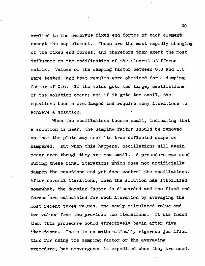
Results from three load cases calculated by the
method contained herein are presented in Figures 4-7 through
4-17. Figures 4-7, 4-8 and 4-9 contain the displacements;
Figures 4-10 and 4-11 show, the forces and moments; Figures
4-12 through•4-15 exhibit the surface stresses across the
plate; and Figures 4-16 and 4-17 represent the normal
stress distribution through the plate thickness.
Concentrated Load—Simply Supported Plate No. 1
Cooper and Shifrin (1954) tested several simply
supported mild-steel plates loaded well into the plastic
range. The load was applied to the plate specimens through
a 0.6 inch diameter rod. Stress-strain curves for the plate
material are presented. Although the material was slightly
anisotropic, isotropy was assumed.
The solid line in Figure 4-18 was redrawn from a
report by Cooper and Shifrin (1954). It represents the
test results of a circular plate .104 inches thick and
17.3125 inches in diameter, supported on a 17-Inch diameter
ring..

56
too
Elastic Stresses from Nadai Ca leu fated Stresses
Top oz of Support
Bottom op zs at Center—
lop op at Center
Bottom op at Support
Figure 4-5 • Badlal Stresses

57
Diameter =• S Inches
Figure 4-6. Plate Model showing Nodal Circles
Tfc~ = 280
t.O L5
r - Inches • *
Figure 4-7. Radial Slopes

58
JOO
280
/.& 2.0 o.s 2.S O t.o
r - Inches Figure 4-8. Lateral Displacement Profiles
t.S
AO
JOO
§ O K
> -O.S
-I.O t.o 2.S 0.5 O
r — inches
Figure 4-9. In-Plane Displacement Profiles
v

7
6 mo
5
A too 3
2
/
O t.5 2.S 0.5 1.0 O r - hches
Figure 4-10. Membrane Forces
280
too -2
2.5 1.5 t.O 2.0 O r-Inches
Figure 4-11. Beading Moments
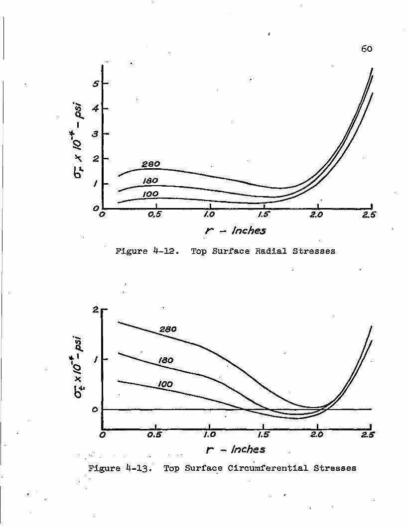
Figure 4-12.
r — inches
Top Surface Radial Stresses
z
28Q
/ tao
too
o
t.5
r - Inches J.o o o.s
Figure 4-13. Top Surface Circumferential Stresses

I
61
3
2
/
1 ° J
5 -2 *
bv -3
-4
-S
-G
/SO
too
I 0.5
± _L » 2.0 /.0 /.ff
r - Inches Figure 4-14. Bottom Surface Radial Stresses
2.5
8. I
*
'o
X
b*
3
2
I
O
-/
-2
^230
-
-
• 1 1 • ' O.S 20 /.O /.S
r - inches Figure 4-15. Bottom Surface Circumferential Stresses
2.5

I
62
_ > 1 1 ti o o
j\\ ,00- M ISO M
2S0—^ "^\\ 280—^ t -¥• C^XiO - pS!
(a) at r « ojs in.
4 2 O 2 4 crp x ID'*— psi
(b) a£ at r~i.Z5in.
x
IOO—N J U loo—^
180—s /77 180—v
280
/
f j / 2 8 0 - J
j. x
07 x iO'* - psi
(c) of at r = 2.35 in.
i I i i L I 4 2 O Z 4 6
x to"* - psi
(d) 07 at r~ 2.50 in.
Figure 4-16. Radial Stress Distribution through the Plate Thickness

63
/OO——^ 1 180 ^ A[\ 280—/ 1ft
L I L 3 2.
i O / -+
J I 2 3
Of * 10 -pst
(a) of at r-o. tsin.
too ^ 1 180 ^
280
I 1 1 1 1 1 1 3 2 2 3
Of x 10-+- psi
(b) 07 at r- t.zsin.
2 3
Of X tO - pst
(c) of at r=2.35 in. (d) of at r = 2.50 in.
Figure 4-17. Circumferential Stress Distribution through the Plate Thickness
1.6
S /.2 *??•
I
^ OA
0.4
Redrawn from Cooper and Shifrin (1954)
—o~ Calculated Results
' 0 O.J 0.2. 0.3
Central Deflection - Inches i
Figure 4-18. Load-Deflection Curve for a Simply Supported Plate with a Concentrated Load—No. 1.
ON 4=-

65
A problem simulating the above test was considered
in the analysis. The results of this analysis are also
shown in Figure 4-18. The boundary was assumed to be simply
supported with unrestrained in-plane movement at the edge.
The loading was assumed to be a concentrated load applied
at the center. Poisson's Ratio was taken as 0.3, Young's
modulus as 30,000,000 psi, the yield stress as 40,000 psi,
and n as 8. These material constants match those of the
test specimen.
The plate as tested was not perfectly flat and
required some initial load.before coming completely down
on the supporting ring. An analysis was made to determine
the effect of an initial load on the test results. Within
the early elastic range of behavior it is assumed that the
test should compare favorably with an elastic analysis.
The elastic analysis indicates that a load of 52 pounds
corresponds to a central deflection of 0.066 inches. A
test point at this same deflection shows a corresponding
load of 170 pounds. The initial load was therefore 118
pounds. Crose (1967) calculated the initial load as 124
pounds. All calculated results have been adjusted to take
into account the initial load.
Figure 4-18 shows a comparison of the load-deflection
results from calculations and the test. The calculated
values are higher than the test values over the load range.
Calculated lateral displacements are presented in Figure

66
4-19- An indication of the yielding occurring in the
material near the center is evident. Figures 4-20 through
4-24 show a comparison between tests and calculations for
radial slopes and strains. The test results are shown as
a range of values to indicate the spread of test data
points. The slight difference between the curves is in a
direction consistent with the difference in the load-
deflection curves in Figure 4-18.*
Calculated stresses at the top and bottom surfaces
are presented in Figures 4-25 through 4-28. Stresses for
two load cases have been redrawn from Crose (1967). The
stresses resulting from the two methods have the same
general shapes however,, no close correlation can be
expected because Crose assumed a sandwich plate with elastic-
perfectly plastic material. Stress distribution through
the plate thickness is presented in Figure 4-29.
Concentrated Load—Simply Supported Plate No. 2
Using the theory of plastic deformation from the •
theory of plasticity, Waghdi (1952) analyzed a simply *
supported, 24S-T aluminum plate for two load cases. Several
plate specimens, made of the same material, were tested and
a comparison was made between the theoretically determined
and the experimentally obtained values of deflection.
A 10 inch diameter plate with a thickness of 0.065
inches was chosen. Young's modulus was 10,000,000 psi and

67
3 4 5 6 7
r - inches Figure 4-19. Lateral
Displacement Profiles—Concentrated Load
2<>r
<o
/<s -
1z -I
a
TesJ- Results -from Cooper and Shifrin (1354)
Calculated Results *
Slope A 10 * — Inches/inch Figure 4-20. Radial Slopes—Concentrated Load

I
68
15
I to
Q. 5
saws
4#1'
WMMTesf Results from Cooper and Sh/fr/n (IS54)
Calculated Results
x 10 — Inches/Inch (Tens/on)
Figure 4-21. Top Surface Radial Strain over the Support
esf Results from Cooper and Shifrin (1954)
Calculated Results
20
et a IO* — Inches/inch (>Compression)
Figure 4-22. Top Surface Circumferential Strain over the Support

69
<o
I
A5
to
* c o.- IffifE Results from Cooper
and Shifrin (1354) Calculated Results
a 12. /<3 .20
ef x 10* - inches/inch (Compression)
Figure 4-23. Top Surface Circumferential Strain at Station % Inch away from Support
/PP 7es"/" Results -from Cooper M0
and Shifrin (1354) Calculated Results J0? >
&r x 10s- Inches/Inch (Tension) »
Figure 4-24. Top Surface Radial Strain at Station •§• Inch away from Support

so
40
30
20
\
-JO
From Crose (/9G7) Calculated Results
-so O.G AO o.z r/a
Figure 4-25. Top Surface Radial Stress—Concentrated Load

ri
SO I-
40
- From Crose (1SG7) Calculated Results
30
20 4 /
X V
10
-feoj
\ \
V
<9
0.2 0.4 O.G
r/a 0.8 AO
Figure 4-26. Bottom Surface Radial Stress—Concentrated Load
%
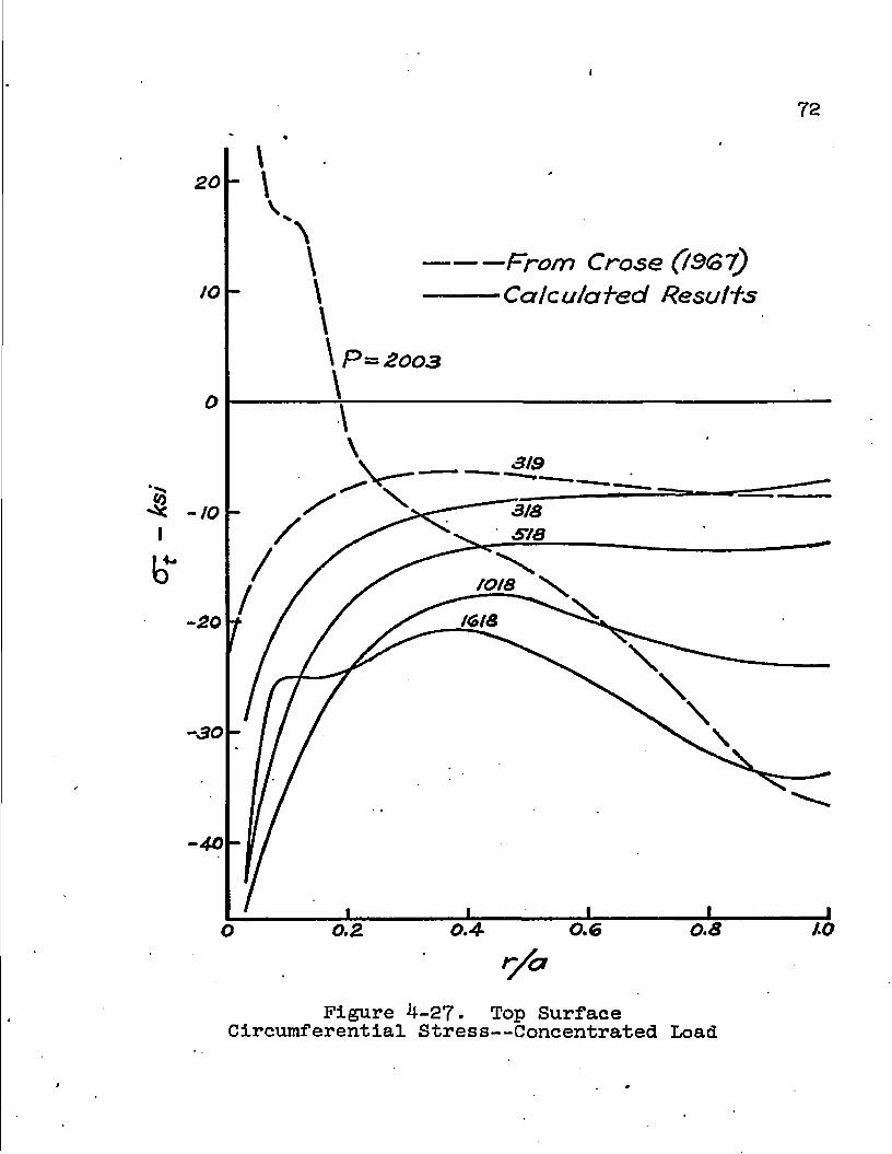
72
20
—From Crose (OGl) —Calculated Results
3/9
-to
tots \
30
to 0.8 0.2 O
Figure 4-27- Top Surface Circumferential Stress—Concentrated Load

I
73
40
30
20
-to
From Crose. (t3G 7) Calculated Results
0.8 /.o o
Figure 4-28. Bottom Surface Circumferential Stress—Concentrated Load

lb
V \ \ v \ . \ > \ J \V x* J \\j5\ \ Vs /] \ //
y /
1 1 1 1 1 1 L I 30 20 10 O iO 20 30 40 SO
cj: - ksi crp. at r- 0.5 in.
40 30 20 20 30 40 SO CTf - ksi
(c) 07 a-f" r-o.sh tn.
L I _L J. J 30 20 IO O /O 20 30 40 SO
oy. - ksi (b) crp. at r~2.4in.
• V \ \ \ \w\s\® \te\(P \
1 1 1 1 1 1 1 1 J 30 20 10
(d) Of
O to 20 30 40 so Ot - ksi at r= 2.4 in.
Figure 4-29- Stress Distribution through the Plate Thickness—Concentrated Load

75
Poisson's ratio was taken as 0.3. The concentrated load
was applied to the center of the plate by means of a one
inch diameter steel rod. The two load cases were:
(1) Load P = 20 pounds for the plate to undergo
large elastic deformation only.
(2) Load P = 500 pounds for the plate to exhibit
large elastoplastic deformations.
The plate was analyzed with the method contained
herein using a yield stress of 69*000 pSi and an n of 2.
Figure 4-30 contains load-deflection curves from this
analysis, from the test, and from Naghdi's analysis. Both
theoretical methods show good agreement with the measured
deflections.
Figures 4-31 and 4-32 contain graphs of forces and
moments for the two load cases as calculated by the two
theoretical analyses. Poor agreement between the methods
is evident. Using the method described herein, it was
found that for load case (1), where P = 20 pounds, the
plate material remained almost perfectly elastic. The
maximum change in the modulus of elasticity was only 1.2#
near'the center. Because the method derived in this dis
sertation has been shown to give excellent agreement with *
"exact" analyses for the case of linear material, and
because it also gives excellent agreement with the test
data for load case (1) in Figure 4-30, it is concluded that
the results of this method in Figure 4-31 are very close to

I
76
QJ -Q 0
1 *
Experimental Points from Naghcti 0352)
— Theoretical Results -from Naghdi (1352)
Calculated Results
\\p= soo
r — Inches
.Figure 4-30. Load-Deflection Curves for a Simply Supported Plate with a Concentrated Load—No. 2
\ f

77
to
8
"S
I
GO
40
20
8 :Q
I *
-20
-40
-GO
Theoretical Results from Naghdi (195Z)
Calculated Results
x JL 2 3
r - Inches
Figure 4-31. Results for a Concentrated Load of 20 lbs.
\

78
—Theoretical Results from Nacfhdi (!B5Z)
—Calculated Results so
40
M
30
20
/O 1000
, SOO
r — Inches
Figure *}— 32. Results for a Concentrated Load of 500 lbs.

79
the true values. The bending moments from Naghdi1s method
then are too large and the membrane forces are generally
too small throughout the plate.

CHAPTER 5
SUMMARY AND CONCLUSIONS
A numerical technique has been presented to analyze
thin structural circular plates possessing nonlinear
material properties without the usual restrictive assump
tion of small deflections. The material is assumed to be
isotropic and homogeneous. The plate and its loading are
taken to be axisymmetric, thereby limiting the problem to
one space variable; however, the plate thickness, the
material properties, and the loading can vary in the radial
direction.
The method is based on finite element procedures.
The governing differential equations are derived directly
from the- plate element for large deflection geometry. The
element stiffness matrix is formed by utilizing the step
wise linearized, differential equations, a fourth order
Runge-Kutta integration scheme, and a searching procedure
which establishes the appropriate boundary conditions in
accordance with the unit displacement method.
The nonlinear material properties are established
through the use of a three parameter stress-strain relation
ship and a yield criterion. An iterative technique is used
to handle the geometric and material nonlinearity. Within
80

81
each Iteration the differential equations are stepwise
linearized and the material properties are held constant.
The load may be applied in one step or in increments if
intermediate solutions are desired.
Because circular plates are widely used, and because
they can support much larger loads when large deflections
and nonlinear material are permitted, the method of
analysis which was developed herein is applicable to many
important engineering structures.
Prom comparison with theoretically "exact" solu
tions, the elastic results were shown to be valid. The
nonlinear material solutions, having no "exact" mathematical
development, were shown to compare favorably to experimental
results from several investigators. On the basis of the
studies made in this dissertation, a feasible method for
obtaining solutions to circular plates subject to large
deflections and nonlinear material has been developed and
presented.

REFERENCES
Birchler, W. D., M. L. Callabresi, and J. E. Murray, "Finite Elements Models for Shells of Revolutions, EES, Series Report No. 21, Engineering Experiment Station College of Engineering, The University of Arizona, 1968.
Cooper, R. M., and G. A. Shifrin, "An Experiment on Circular Plates in the Plastic Range," Proceedings of the Second U.S. National Congress of Applied Mechanics, Ann Arbor, ±95^, pp. 527-534.
Crose, J. G., "A Large Deflection Analysis Method for Transversely Loaded Elastic-Perfectly Plastic Circular Plates," Doctoral Dissertation, University of Illinois, 1967..
Den Hartog, J. P., Advanced Strength of Materials, McGraw-Hill Book Company, Inc., New York, ±952.
Goldberg, J. E., and R. M. Richard, "Analysis of Nonlinear Structures," Journal of the Structural Division, ASCE, Vol. 893 No. ST4, Proc. Paper 3fc>o4, August, 1963, pp. 333-351.
Hildebrand, F. B. Introduction to Numerical Analysis, McGraw-Hill Book Company, inc., .New York, 1956.
Hopkins, H. G., and W. Prager, "On the Load-Carrying Capacities of Circular Plates," Journal of the Mechanics ajid Physics of Solids, Vol. 2, No. 1, October, 1953* PP« 1-13.
McPherson, A. E., W. Ramberg, and S. Levy, "Normal-Pressure Tests of Circular Plates with Clamped Edges," NACA, Technical Report 7^-8, 19^2.
Naghdi, P. M., "Bending of Elastoplastlc Circular Plates with Large Deflections," Journal of Applied Mechanics, ASME, Vol. 19, No. 3, September, 1952, pp. 293-300.
Novozhilov, V. V., Foundations of the Nonlinear Theory of Elasticity, Grayiocit Press, Rochester, N.Y., J.953*
82 *

83
Onat, E. T. and R. M. Haythornwaite, "The Load-Carrying Capacity of Circular Plates at Large Deflection,11 Journal of Applied Mechanics., ASME, Vol. 23, March, 1956, pp. 49-55.
Richard, R. M., "A Study of Structural Systems Having Conservative Nonlinear Elements, Doctoral Dissertation, Purdue University, 196I.
Richard, R. M., and J. E. Goldberg, "Analysis of Nonlinear Structures: Force Method, Journal of the Structural Division, ASCE, Vol. 91* No. ST6, Proc. .Paper 4^53, December, 1965* PP- 33-48.
Richard, R. M., and M. L. Callabresi, "Nonlinear Finite Element Analysis," Engineering Experiment Station Report No. 13, The University of Arizona, Tucson, Arizona, 1967 •
Richard, R. M. and J. R. Blacklock, "Finite Element Analysis of Inelastic Structures," AIAA Journal, Vol. 7* March, 1969* PP« 432-438.
Timoshenko, S., and S. Woinowsky-Krieger, Theory of Plates and Shells, McGraw-Hill Book Company, inc., New York, 1959•
Way,.S., "Bending of Circular Plates with Large Deflection," Transactions3 ASME, Vol. 56, 1934, pp. 627-636.
Wempner, G. A., and R. Schmidt, "Large Symmetric Deflections of Annular Plates," Journal of Applied Mechanics, ASME, December, 1958* pp. 449-452.