reference architecture data storage infrastructure
TRANSCRIPT
DATA STORAGE INFRASTRUCTURE
REFERENCE ARCHITECTURE
FOR MILESTONE VIDEO SURVEILLANCE SYSTEM

REFERENCE ARCHITECTURE
2
INTRODUCTION
HOW XPROTECT AND EXOS X 5U84 WORK TOGETHER
PERFORMANCE AND CAPACITY PLANNING
SOLUTION COMPONENTS
CONCLUSION
3
4
10 12 16
CONTENTS

REFERENCE ARCHITECTURE
3
VIDEO MANAGEMENT SYSTEM (VMS) OVER SAN With data analytics now being collected from video data content, VMS tasks have gone far beyond simple security monitoring. New features—including IoT end device monitoring, video data analytics, and policy-driven data mining of video and images—are becoming widely adopted in VMS platforms, continue to drive data volume growth, and lead to data storage capacity expansion.
When designing a data storage infrastructure to meet VMS video/audio retention requirements, on-prem iSCSI SAN (Storage Area Network) and cloud-based implementations are two alternatives to traditional, all-in-one VMS solutions such as Network Video Recorder (NVR) or dedicated Digital Video Recorder (DVR). When implementing a solution over an on-prem iSCSI SAN, you’ll have:
• Scalability. Scale to petabyte capacities, when needed, at lower cost.
• Speed. High throughput in saving video recordings with higher frame rates without losing a single frame.
• Data Availability and Reliability. RAID-like protection for longer retention of video assets without data loss.
• High Security. Block storage and drive encryption minimize the likelihood of unwanted data intrusion.
• Ease of Management. Centralized management for VMS data access, monitoring, and distribution.
This joint VMS solution reference architecture introduces an on-prem iSCSI SAN implementation of Milestone System VMS XProtect® Corporate with the Seagate® Exos™ X 5U84 storage platform and demonstrates a VMS data storage solution that:
• scales to 1.3PB in a single disk enclosure
• delivers throughput up to 5.5GB/s and 7.0GB/s for sequential write and read
• offers an exceptionally low total cost of ownership (TCO)
JOINT SOLUTION RESULTS This solution was validated by Milestone and proves compelling values that are flexible enough to meet—and exceed—customers’ dynamic video asset retention requirements and budget.
Introduction

REFERENCE ARCHITECTURE
4
1. MILESTONE XPROTECT ARCHITECTURE OVERVIEW The Milestone XProtect software package offers installation flexibility with multiple components that can be deployed on either a single server or multiple physical servers based on desired use cases. To build a validation test configuration, we distributed these components on multiple physical servers by following Milestone validation test requirements. The components are listed here for quick reference:
• Management server. Oversees the system configuration, distributes the system configuration to other system components such as the recording servers, and facilitates user authentication. This is the central VMS component.
• Recording server. Responsible for all communication, recording, and event handling related to devices such as cameras, video and audio encoders, I/O modules, and metadata sources.
• Media database. Stores the retrieved video, audio, and metadata and supports various unique features including multistage archiving, video grooming, encryption, and adding a digital signature to the recordings.
• Event server. Handles the tasks related to events, alarms, maps, and third-party integrations via the Milestone Integration Platform.
• Log server. Documents three types of logs: a system log, an audit log, and a rule-triggered log. The log server is typically installed on the management server and generally uses the same SQL server as the management server but has its own SQL database. If higher performance from the SQL database (SQL DB) is desired, we suggest that you install this component on a separate SQL server.
• SQL server. Stores the SQL databases used by the management server, the event server, and the log server. For best performance, this component is installed on a separate physical server that has no other running applications.
• Mobile server. Distributes video streams from recording servers to XProtect Mobile Client or XProtect Web Client.
How XProtect and Exos X 5U84 Work Together

REFERENCE ARCHITECTURE
5
XPROTECT WORKFLOW The following diagram depicts a high-level workflow of Milestone XProtect software in the validation test over Seagate storage through iSCSI SAN.
In the test one unit, the load server that generates synthetic bit streams is used in place of physical IP cams. The server generates synthetic video bit streams that feed recording servers A and B. One unit of the management server and the SQL DB server are deployed to orchestrate all VMA activities and SQL DB operations to support logs and events. One unit of the web client is used to perform video play-back.
REDUNDENCY AND HIGH AVAILABILITY It’s worth mentioning that additional recording and SQL servers could be added to either increase the performance or to add failover capability, as needed. Milestone VMS is fully capable of providing such high availability and disaster recovery features, and users are highly recommended to consult the Seagate sales team when such needs are required.
2. SEAGATE STORAGE ARCHITECTURE OVERVIEW
READ/WRITE CACHING OPTIMIZATION FOR STREAMING At the core of this video surveillance storage infrastructure design is the Seagate Exos X 5U84 storage platform. The software running on the system is equipped with a feature called Stream Conductor (SC). SC profiles IOs as they come into the storage. The read and write caching engines are optimized for profiled IOs that fit into streaming patterns to ensure that optimal
Recorder A
IP SAN(Exos X 4U84)
(DIAGRAM 1)
1G mgmt. network
10G for SQL Ops
SQL Server
Web Clientreply agent
Mgmt. Server
Recorder B
Load Server
IPcam BitStream
IPcam BitStream
IPcam BitStream
4 Mbps stream on
1G network
10G data IO to IP SAN
IPcam BitStream
IPcam BitStream

REFERENCE ARCHITECTURE
6
bandwidth is available for the video streaming. Most VMS applications require high bandwidth for their data storage. Seagate read caching uses an algorithm called least recently used (LRU) to evict data in the cache based on the frequency the data is used. For read performance enhancement, the Seagate read cache engine also adopted a read-ahead algorithm where roughly 64 streams per volume can increase the concurrency. In this read-ahead algorithm, an adaptive read is used to review the host IO requests and then to pre-fetch the data accordingly and appropriately. When write caching is called for, the Seagate write cache engine examines data and determines if it is clean or dirty. When data is determined to be already de-staged or clean, the cache engine performs the latest eviction policy on the write IO. For dirty data, the de-stage algorithm has a lot of write optimizations, one of which is to support an elevator-based approach where the software sweeps across all LBA spaces to try to make data more sequential to the disks and flush the dirty IOs as often as possible. In addition, those sweep processes have stripe awareness with a goal to de-stage full stripe writes as much as possible.
Host IO Streams
Host IO Manager
IO Profiler
Disk Disk Disk Disk Disk Disk
Stream Conductor
Cache
RAID
Backend

REFERENCE ARCHITECTURE
7
ADAPT PERFORMANCE AND RELIABILITY Seagate ADAPT stands for Autonomic Distributed Allocation Protection Technology. This technology offers superior data protection and better data rebuild performance than those of traditional RAID. With ADAPT, the raw disk storage media is logically divided into chunks and zones. The user data and parity information are optimally distributed among all those participating chunks in the zones. When disk drive failure occurs, the parity data from two or more drives come to the rescue, resulting in a much fast data rebuild and shorter system recovery time. This type of RAID-like data protection approach:
• allows mixed drive sizes and types (SSD and HDD) and enables seamless capacity expansion up to 128 drives in a single disk group which is an abstraction of grouping disk drives
• provides variable stripe width with user-selectable data protection of 8+2 or 16+2 for better handling of fault tolerance and performance enhancement
• allocates dynamic spares so that sufficient space is intelligently determined by the controller software
• rebuilds data much faster when drive failure occurs without significant impact on data IO performance. It also provides nearly 10 times the reliability than traditional RAID 6
Fast rebuild time is critical to maintain storage system stability, especially when the storage media is ever-increasing in capacity and density. The following data provides a quick comparison of the time savings between traditional RAID and Seagate ADAPT.
Matrix RAID 6 (8+2)
24 Drive ADAPT
84 Drive ADAPT
120 Drive ADAPT
Rebuild Time (hours) - 1st drive down
55.5 24 7 5.3
Rebuild Time (hours) - 2nd drive down
55.5 9 1 0.41
Performance 1st drive down -41% -23% -8% -6%
Performance 2nd drives down
-62% -37% -14% -10%

REFERENCE ARCHITECTURE
8
3. ISCSI SAN ADVANTAGES IN VIDEO SURVEILLANCE STORAGE SAN protocols have been in the market for a long time, with the two most common types being Fiber Channel and iSCSI. Choosing between Fiber Channel SAN (FC SAN) and iSCSI SAN is not a matter of better or worse—the choice depends on the option that best fits the use case. Listed below are the reasons why we recommend using an iSCSI SAN solution when deploying VMS storage infrastructure over iSCSI SAN.
• Shared Resources. iSCSI SAN is a storage area network that connects application servers and storage devices by TCP/IP. It allows multiple hosts to read and write data to the same disk system simultaneously. This function takes advantage of the entire disk-based primary tier of storage rather than dedicating storage resources to an individual server.
• High Performance. In SAN storage infrastructure, iSCSI and FC are two primary SAN protocols. Although iSCSI SAN inherently carries higher latency from TCP/IP than that of FC SAN, it is a dedicated LAN infrastructure for connectivity between VMS servers and storage systems. iSCSI will not perform less than FC, hence FC or iSCSI may matter depending on the use case.
• Close-Loop VMS Solutions. iSCSI SAN offers cost-effective storage infrastructure that balances data availability, resiliency, and scalability with relatively low TCO when compared to FC SAN.
• Ease to Scale. iSCSI SAN acts as a centralized single storage network with shared storage resources. Since servers are connected to a shared storage pool, the pool size can be expanded or shrunk by adding or removing storage systems.
Drive Size (TB)
ADAPT vs RAID: Probability of data loss over 5 years
010-7
10-6
10-5
10-4
10-3
4 8 122 6 10 14 16
14drv RAID 12+2 w/2 spares16drv ADAPT 8+2
The following chart displays the reliability of Seagate ADAPT over traditional RAID.

REFERENCE ARCHITECTURE
9
• Security. When connected, the VMS edge/recording servers to which the IP cams feed bit streams treat the iSCSI SAN storage as if it were a local drive. When the file system and OS are bundled together, it increases the entry barrier for those unwanted intrusions. With Seagate self-encryption disk drives, the security is heightened for non-open infrastructure video surveillance solutions at places such as airports and city subways.
Limitation of iSCSI SAN We recommend using FC SAN in the following situations:
• when the connection between recording servers and storage are not in the local LAN
• when super high data throughput occurs in batch processing
• for VMS application servers where the CPU is already near its maximum utilization
• for disaster recovery of the SQL DB of VMS

REFERENCE ARCHITECTURE
10
Total storage capacity and aggregated performance are two major factors that need to be included in VMS infrastructure design consideration. Some design fundamentals are discussed below to provide a proper sizing guide and best practice reference.
1. VIDEO DATA ATTRIBUTES Video Image Resolution. Standard and high definition are common terms that define the number of distinct pixels in each dimension. In this example, the resolution is 1920 x 1080:
• 1080 is the vertical resolution
• 1920 is the horizontal resolution
Frame Size. V * H * CD, where:
V - Vertical resolution
H - Horizontal resolution
CD - Color Depth (24-bit, 48-bit, 64-bit; the higher the CD, the bigger the data size becomes)
Video File Size. Frame size * fps * time duration, where:
FPS – the number of frames displayed per second; the range is from 12fps to 60fps
Time – time duration of video data acquisition
2. PERFORMANCE PLANNING Most VMS applications separate video/audio streaming data from the chatty metadata that is associated with the video/audio data. In our lab observation there were three types of throughputs out of the VMS processing. These were:
• Recording. Bit streaming from IP cams to the recording servers. After aggregation, a certain percentage of the bit streaming data from IP cams is funneled to iSCSI archiving storage in sequential write fashion.
• Re-direction. Happens when bit streaming from IP cams gets redirected to the monitor/client without going through the recording server. This part of the streaming is not sent to iSCSI SAN storage for archiving; rather, it is archived on the recording server’s local storage.
• Replay. When a single or multiple XProtect client or monitor agent calls for review of archived video from the recording server (archiver), it constitutes the sequential read IO from the iSCSI SAN storage.
The total bandwidth requirement for iSCSI SAN storage should be calculated as follows:
Aggregated recording server throughput + total number of replay throughput
It is worth noting that, in the event-trigger video capture mode of Milestone XProtect, when video with motion detection is occurring at the rate of 20-30% of time, not all IP cam streaming data is written to the iSCSI SAN storage. In this case, the ratio of data written to the iSCSI SAN storage is an estimate.
1:0.24 or 24% (of the IP cam streaming bits)
Performance and Capacity Planning

REFERENCE ARCHITECTURE
11
3. CAPACITY SIZING Calculation of video bit rate is quite complex and is not covered in this paper. However, total storage capacity calculation is relatively straightforward. We calculated the total storage capacity as follows:
IP cam bit rate x total number of IP cams x total hours of day of recording x compression ratio x retention days
If any of the variables in the above formula has a positive delta, such a delta value should be included to accommodate for future capacity expansion.
4. NETWORK BANDWIDTH CONSIDERATION Most VMS applications allow separation of management network traffic from streaming video data traffic. In the database operation, the management data flows are characterized as small, random read and write. They do not constitute a significant amount of data streaming to the iSCSI SAN storage; therefore, they should be included when designing the VMS management network infrastructure.
High speed and bandwidth data networks are critical in connecting the VMS application servers in the XProtect cluster to iSCSI SAN. Following the best practice, at least two network interfaces are recommended to be installed on each physical VMS application server, one being 10GigE that serves the data traffic, and the other being 1GigE which keeps the management traffic flowing.
We recommend the load server is set to use a 10G network for its feed in Proof of Concept (POC) testing to ensure a big enough pipeline is ready for data ingestion.
5. PERFORMANCE RESULTS The performance numbers are documented below for reference. Given the limitation of the VMS application server used in this Milestone XProtect validation, it is apparent the storage performance capability was not maximized.
Number of Recorder
Video Resolution
Total Cameras
Motion-Detection
Number of Playbacks CPU% Total MB/s Disk IO Network
Dell EMC PowerEdge RS640
1920 X 1080 Stripes-8M bit
400 None No 47-72 420.6 1753 4.4Gb/s
Dell EMC PowerEdge RS640
1920 X 1080 Stripes-8M bit
400 None No 47-72 447.3 1761 4.4Gb/s

REFERENCE ARCHITECTURE
12
1. THE KEY SOLUTION COMPONENTS The following hardware and software were used and deployed in the Milestone XProtect validation test.
VMS Application Host Servers
• one unit of VMS management server including SQL DB
• two units of recording server
• one unit of feed (load) server
• one unit of XProtect Client for video play-back
Each of the servers has identical hardware configuration and base OS. SQL DB is configured to leverage local server SSD drives for performance.
Solution Components
Data Network Switch
• one unit of 10GigE data network switch that carries audio/video recording data
• one unit of 1GigE management network to transport management data
• each server is equipped with two NICs, one for 1GigE management and one for the 10GigE data network. There is no routing on the data network, therefore the network hop count is zero between iSCSI storage and the archiver server
VMS Application Server (Dell EMC Power Edge R640)
OS Windows 2019 Standard Server
Network 1 x 10GigE; 1 x 1GigE
CPU Intel® Xeon Silver [email protected], 2095Mhz, 16 Cores, 32 Logical Processors
Memory 192gb
Local SSD Dell PERC H740P Mini SCSI 480GB
Dell EMC Switch
Model S4148F
Port Speed 10GigE (data) ; 1 x 1GigE (management)
OS OS10
Cable Fiber optical
SFPs Dell 10GigE

REFERENCE ARCHITECTURE
13
Seagate Exos Storage Platform
• each controller has four NIC interfaces, and each interface is capable of handling 10GigE with a total of 40GigE throughput for each controller
• two disk pools are created on the storage and each pool contains 40 disk drives
• two 35TB volumes are created using ADAPT with identical performance configuration enabled. Write-back mode and progressive read are enabled on each volume connecting the recording servers
Controller
Enclosure Exos X 5U84
SAS IO Controller 4865 CNC
Firmware Version GTS265R14-01
Cable Fiber optical
SFPs Seagate 10GigE
Milestone XProtect and the Version
2. ISCSI INITIATOR CONFIGURATION The Windows 2019 server needs to run as an iSCSI initiator to render iSCSI services. To do this, you must add and enable the iSCSI initiator role and service before you install the XProtect application on the server. The following steps are necessary to create an iSCSI drive on Windows 2019 standard servers.
• add a role in Server Manager
• confirm the role you selected
• reboot the server and enable the iSCSI initiator
• discover all iSCSI ports by supplying the data serving interface IPs on the storage
• discover the raw storage device exported from the storage
• find the iSCSI device in Computer Management and complete the following steps to get the drive ready for use:
• bring the drive online
• initialize the drive
• create a partition based on the desired capacity
Security Center Components Version
XProtect Corporate Mgmt. 2020 R2
Feeder ImDisk Virtual Disk Driver
XProtect Recording Server 20.2A
REFERENCE ARCHITECTURE
14
• assign the drive letter to the iSCSI device
• format the drive in 64K as suggested by Milestone best practice
• The iSCSI queue depth (QD) can be changed by updating the Windows registry to further tweak it for optimal performance by doing the following: Computer\HKEY_LOCAL_MACHINE\SYSTEM\CurrentControlSet\Services\iScsiPrt\Parameters NumberOfRequests = 16-255 (REG_DWORD) Note: We did not enable iSCSI CHAP security for testing simplicity.
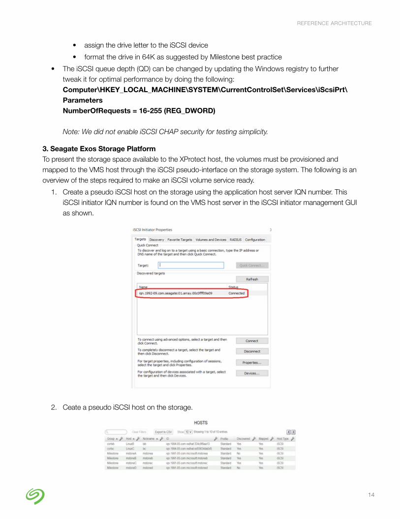
3. Seagate Exos Storage Platform To present the storage space available to the XProtect host, the volumes must be provisioned and mapped to the VMS host through the iSCSI pseudo-interface on the storage system. The following is an overview of the steps required to make an iSCSI volume service ready.
1. Create a pseudo iSCSI host on the storage using the application host server IQN number. This iSCSI initiator IQN number is found on the VMS host server in the iSCSI initiator management GUI as shown.
2. Ceate a pseudo iSCSI host on the storage.
REFERENCE ARCHITECTURE
15
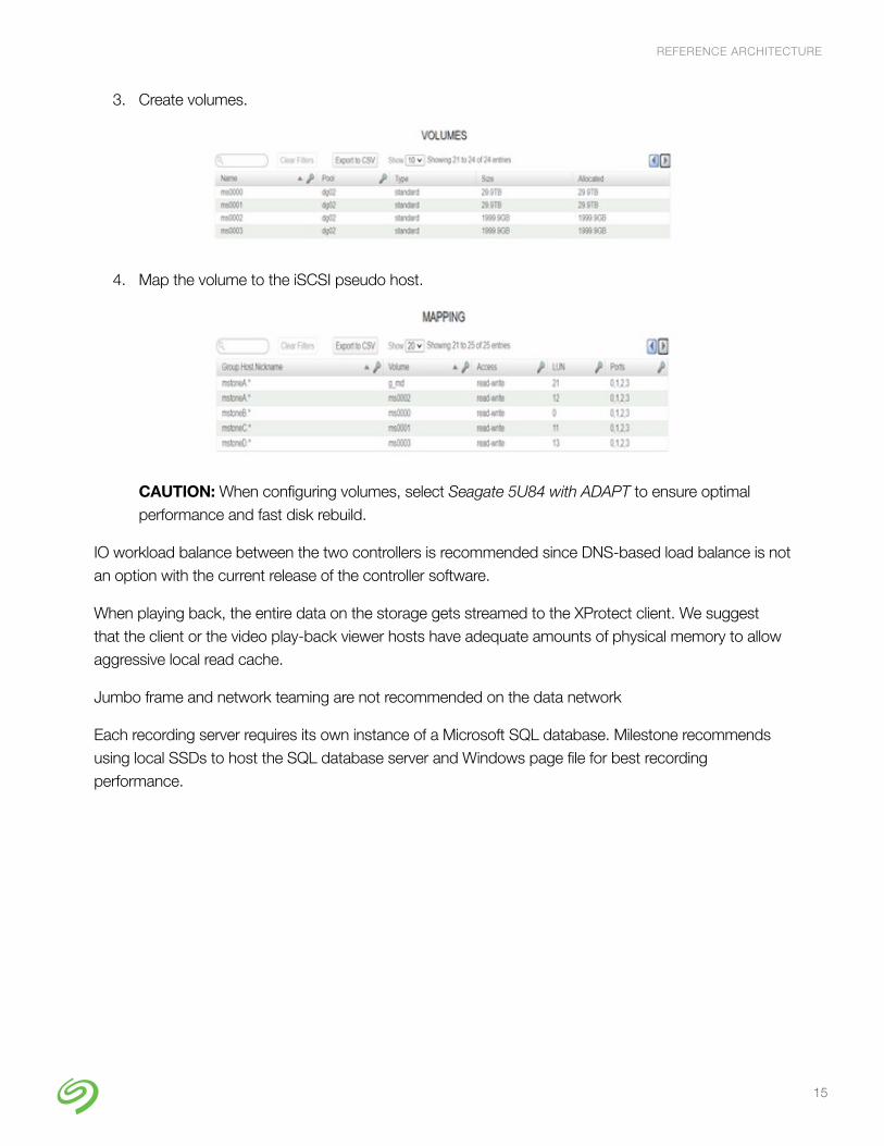
3. Create volumes.
4. Map the volume to the iSCSI pseudo host.
CAUTION: When configuring volumes, select Seagate 5U84 with ADAPT to ensure optimal performance and fast disk rebuild.
IO workload balance between the two controllers is recommended since DNS-based load balance is not an option with the current release of the controller software.
When playing back, the entire data on the storage gets streamed to the XProtect client. We suggest that the client or the video play-back viewer hosts have adequate amounts of physical memory to allow aggressive local read cache.
Jumbo frame and network teaming are not recommended on the data network
Each recording server requires its own instance of a Microsoft SQL database. Milestone recommends using local SSDs to host the SQL database server and Windows page file for best recording performance.

REFERENCE ARCHITECTURE
16
ConclusionThis joint solution delivers the performance, security, availability, and scalability demanded by VMS application infrastructure designs. By allowing surveillance management to store, archive, and manage the recorded videos/audio centrally over a distributed storage infrastructure, the solution provides a cost-effective way to increase the total number of IP cameras or IoT devices supported and managed by Milestone XProtect without fear of running out of storage capacity.
Video Surveillance Solutions www.seagate.com/solutions/video-surveillance/
© 2021 Seagate Technology LLC. All rights reserved. Seagate, Seagate Technology, and the Spiral logo are registered trademarks of Seagate Technology LLC in the United States and/or other countries. Exos and Seagate Secure are either trademarks or registered trademarks of Seagate Technology LLC or one of its affiliated companies in the United States and/or other countries. All other trademarks or registered trademarks are the property of their respective owners. Seagate reserves the right to change, without notice, product offerings or specifications. SB513.1-2101US January 2021
Ready to Learn More? Visit us at seagate.com