registered 1 camac - a - 2004 - acson international tm2004/camac-a... · modular air cooled chiller...
TRANSCRIPT

Modular Air Cooled Chiller
CAMAC - A - 2004_1
AMAC170A/ARAMAC210A/ARAMAC340A/ARAMAC420A/ARAMAC510A/ARAMAC630A/ARAMAC720A/ARAMAC840A/ARAMAC1050A/ARAMAC1260A/AR
Models:
ISO 9002
REGISTEREDS&E

Contents
1. Features ....................................................................................................................... 1 2. Nomenclature ..............................................................................................................2 3. Specifications..........................................................................................................3 - 4 4. Performance Characteristics ..................................................................................5 - 6 5. Technical Data............................................................................................................. 7 6. Outlines and Dimensions .....................................................................................8 - 10 7. Control System ...................................................................................................11 - 13 8. Location and Installation ....................................................................................14 - 15 9. Hydraulic System ...............................................................................................16 - 17 10. Trouble Shooting ..................................................................................................... 18 11. Main Parts List ......................................................................................................... 19

AMAC units are high thermodynamic engineering products, studied with high accuracy in balancing compressors, condensers and evaporators in order to offer high performances and wide safety margins. The choose of the materials and the equipment adopted for the products has been made without any compromises, taking care of quality and long life purposes. The products meet ISO 9001 requirements, an assurance beyond any doubts of the high producing standards followed by ACSON. Working Reliability In summer mode (the mode is simply selected by means of a switch) the unit produces chilled water through a plate exchanger while the condenser coils dissipate the heat rejection. In winter mode plate heat exchanger works as a water condenser to produce hot water while condenser coils dissipate cooling capacity to the ambient air. The periodic defreezing, necessary during low temperature functioning of the unit is run by the system by means of automatic switching of the 4-ways inversion cycle valve. Modular Design AMAC170A(R) and AMAC210A(R) are designed as the 2 original modules, different numbers of modules can be combined to satisfy different load. The largest combination is 8 modules, it convenient to transportation and installation. Highly Flexible Design The AMAC units are available in sizes covering a range from 50 to 420 kW nominal cooling capacity and with availability of many accessories, and the applications of high tech control and safety devices, give to these products high flexibility for their installation in commercial, residential and industrial environments. It couples with different type of fan coil or AHU, and satisfies different area by modular combination. Low Installation Costs The complete assembly of the units and function testing at the factory reduces the cost of installation on site. A rigid steel base distributes the weight of the unit to the support points and allows simple installation by an easy access to the lifting points. Factory Testing Each unit is pressure tested, vacuum tested, evacuated and charged with refrigerant requested. It is then tested at the factory’s test bench under the design conditions specified by the customer. Upon request, a second series of tests can be carried out witnessed by the customer. Before shipment, each unit is re-checked for pressure and refrigerant charge control.
1. Features
1

A MAC 170 A (R) ---F** Description Heat Pump Generation Norminal Cooling Capacity
Air-Cooled Chiller Brand: ACSON
General Specification Compressor ACSON Modular Air Cooled Chillers are equipped with highly efficient, reliable and silence reciprocated compressor with internal overload protection. The compressor adopts hermetic type to further eliminate operating noise and vibration. Air-cooled Condenser The two air cooled condenser coils with V-shaped is consist of staggered rows of 3/8" OD seamless copper tube, mechanically expanded onto die formed aluminum fins to ensure optimum heat exchange capability. Condenser Fan Motor To achieve the high air charge requirement, the unit is equipped with the high airflow propeller fan which is made of acryl styrene resin. The fan is direct driven by weatherproof single-phase motor to ensure reliable continuous operation. Evaporator The heat exchanger is made of stainless steel plates closely arranged and brazed together to ensure high heat exchange efficiency. The complete heat exchanger is insulated with thermal closed cell nitric rubber foam to give optimum thermal insulation. Refrigerant Circuit The refrigerant circuit is factory brazed and evacuated before accurately charged with R22 to ensure optimum operating requirement. To ensure flawless continuous operation, each refrigerant circuit is equipped with a carefully sized thermostatic expansion valve. Additional Safety Protection The modular air-cooled chillers are equipped with intelligently designed safety control to ensure continuous safe operation. High and low pressure switch is provided in cooling models to prevent the compressor damage resulting from both abnormally high discharge head pressure and low pressure due to insufficient gas. The heat pump models are provided with a high-pressure switch. Flow switch is provided in the unit to protect against damage to the water pump. The standard mechanical controller provides accurate water temperature control in the circuit by closely monitoring and reacting to the input from the water entering temperature, water leaving temperature and ambient air temperature.
2. Nomenclature
2
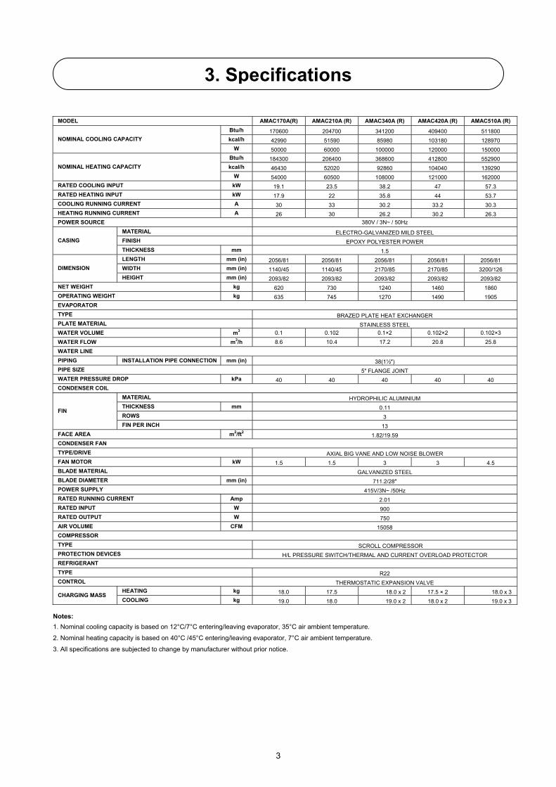
3. Specifications
MODEL AMAC170A(R) AMAC210A (R) AMAC340A (R) AMAC420A (R) AMAC510A (R) Btu/h 170600 204700 341200 409400 511800 kcal/h 42990 51590 85980 103180 128970 NOMINAL COOLING CAPACITY
W 50000 60000 100000 120000 150000 Btu/h 184300 206400 368600 412800 552900 kcal/h 46430 52020 92860 104040 139290 NOMINAL HEATING CAPACITY
W 54000 60500 108000 121000 162000 RATED COOLING INPUT kW 19.1 23.5 38.2 47 57.3 RATED HEATING INPUT kW 17.9 22 35.8 44 53.7 COOLING RUNNING CURRENT A 30 33 30.2 33.2 30.3 HEATING RUNNING CURRENT A 26 30 26.2 30.2 26.3 POWER SOURCE 380V / 3N~ / 50Hz
MATERIAL ELECTRO-GALVANIZED MILD STEEL FINISH EPOXY POLYESTER POWER CASING THICKNESS mm 1.5 LENGTH mm (in) 2056/81 2056/81 2056/81 2056/81 2056/81 WIDTH mm (in) 1140/45 1140/45 2170/85 2170/85 3200/126 DIMENSION HEIGHT mm (in) 2093/82 2093/82 2093/82 2093/82 2093/82
NET WEIGHT kg 620 730 1240 1460 1860 OPERATING WEIGHT kg 635 745 1270 1490 1905 EVAPORATOR TYPE BRAZED PLATE HEAT EXCHANGER PLATE MATERIAL STAINLESS STEEL WATER VOLUME m3 0.1 0.102 0.1×2 0.102×2 0.102×3 WATER FLOW m3/h 8.6 10.4 17.2 20.8 25.8 WATER LINE PIPING INSTALLATION PIPE CONNECTION mm (in) 38(1½″) PIPE SIZE 5" FLANGE JOINT WATER PRESSURE DROP kPa 40 40 40 40 40 CONDENSER COIL
MATERIAL HYDROPHILIC ALUMINIUM THICKNESS mm 0.11 ROWS 3
FIN
FIN PER INCH 13 FACE AREA m2/ft2 1.82/19.59 CONDENSER FAN TYPE/DRIVE AXIAL BIG VANE AND LOW NOISE BLOWER FAN MOTOR kW 1.5 1.5 3 3 4.5 BLADE MATERIAL GALVANIZED STEEL BLADE DIAMETER mm (in) 711.2/28″ POWER SUPPLY 415V/3N~ /50Hz RATED RUNNING CURRENT Amp 2.01 RATED INPUT W 900 RATED OUTPUT W 750 AIR VOLUME CFM 15058 COMPRESSOR TYPE SCROLL COMPRESSOR PROTECTION DEVICES H/L PRESSURE SWITCH/THERMAL AND CURRENT OVERLOAD PROTECTOR REFRIGERANT TYPE R22 CONTROL THERMOSTATIC EXPANSION VALVE
HEATING kg 18.0 17.5 18.0 x 2 17.5 × 2 18.0 x 3 CHARGING MASS COOLING kg 19.0 18.0 19.0 x 2 18.0 x 2 19.0 x 3
Notes: 1. Nominal cooling capacity is based on 12°C/7°C entering/leaving evaporator, 35°C air ambient temperature.
2. Nominal heating capacity is based on 40°C /45°C entering/leaving evaporator, 7°C air ambient temperature.
3. All specifications are subjected to change by manufacturer without prior notice.
3

MODEL AMAC630A (R) AMAC720A(R) AMAC840A(R) AMAC1050A(R) AMAC1260A(R)
Btu/h 614100 716500 818800 1023500 1228200
kcal/h 154760 180560 206350 257940 309530 NOMINAL COOLING CAPACITY
W 180000 210000 240000 300000 360000
Btu/h 619200 759300 825600 1032000 12384400
kcal/h 156050 191310 208070 260090 312110 NOMINAL HEATING CAPACITY
W 181500 222500 242000 302500 363000
RATED COOLING INPUT kW 70.5 80.8 94 117.5 141
RATED HEATING INPUT kW 66 75.7 88 110 132
COOLING RUNNING CURRENT A 33.3 123 33.4 33.5 33.6
HEATING RUNNING CURRENT A 30.3 108 30.4 30.5 30.6
POWER SOURCE 380V / 3N~ / 50Hz
MATERIAL ELECTRO-GALVANIZED MILD STEEL
FINISH EPOXY POLYESTER POWER CASING
THICKNESS mm 1.5
LENGTH mm (in) 2056/81 2056/81 2056/81 2056/81 2056/81
WIDTH mm (in) 3200/126 4230/167 4230/167 5260/207 6290/248 DIMENSION
HEIGHT mm (in) 2093/82 2093/82 2093/82 2093/82 2093/82
NET WEIGHT kg 2190 2590 2920 3650 4380
OPERATING WEIGHT kg 2235 2650 2980 3725 4470
EVAPORATOR
TYPE BRAZED PLATE HEAT EXCHANGER
PLATE MATERIAL STAINLESS STEEL
WATER VOLUME m3 0.102×3 0.102×4 0.102×4 0.102×5 0.102×6
WATER FLOW m3/h 31.2 36.2 41.6 52 62.4
WATER LINE
PIPING INSTALLATION PIPE CONNECTION mm (in) 38(1½″)
PIPE SIZE 5" FLANGE JOINT
WATER PRESSURE DROP kPa 40 40 40 42 43
CONDENSER COIL
MATERIAL HYDROPHILIC ALUMINIUM
THICKNESS mm 0.11
ROWS 3 FIN
FIN PER INCH 13
FACE AREA m2/ft2 1.82/19.59
CONDENSER FAN
TYPE/DRIVE AXIAL BIG VANE AND LOW NOISE BLOWER
FAN MOTOR kW 4.5 6 6 7.5 9
BLADE MATERIAL GALVANIZED STEEL
BLADE DIAMETER mm (in) 711.2/28″
POWER SUPPLY 415V/3N~ /50Hz
RATED RUNNING CURRENT Amp 2.01
RATED INPUT W 900
RATED OUTPUT W 750
AIR VOLUME CFM 15058
COMPRESSOR
TYPE SCROLL COMPRESSOR
PROTECTION DEVICES H/L PRESSURE SWITCH/THERMAL AND CURRENT OVERLOAD PROTECTOR
REFRIGERANT
TYPE R22
CONTROL THERMOSTATIC EXPANSION VALVE
HEATING kg 17.5 × 3 71.5 17.5 x 4 17.5 × 5 17.5 × 6 CHARGING MASS
COOLING kg 18.0 × 3 75.0 18.0 × 4 18.0 × 5 18.0 × 6
4
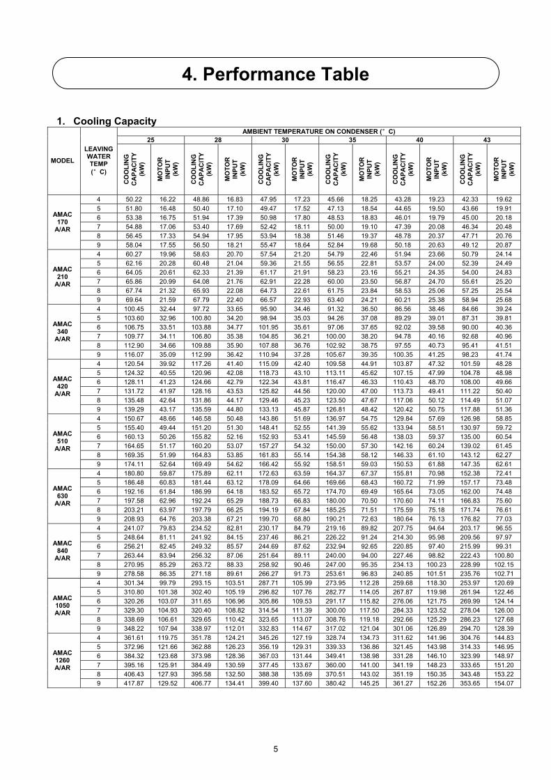
4. Performance Table
1. Cooling Capacity AMBIENT TEMPERATURE ON CONDENSER (°C)
25 28 30 35 40 43
MODEL
LEAVING WATER TEMP (°C)
CO
OLI
NG
C
APA
CIT
Y (k
W)
MO
TOR
IN
PUT
(kW
)
CO
OLI
NG
C
APA
CIT
Y (k
W)
MO
TOR
IN
PUT
(kW
)
CO
OLI
NG
C
APA
CIT
Y (k
W)
MO
TOR
IN
PUT
(kW
)
CO
OLI
NG
C
APA
CIT
Y (k
W)
MO
TOR
IN
PUT
(kW
)
CO
OLI
NG
C
APA
CIT
Y (k
W)
MO
TOR
IN
PUT
(kW
)
CO
OLI
NG
C
APA
CIT
Y (k
W)
MO
TOR
IN
PUT
(kW
)
4 50.22 16.22 48.86 16.83 47.95 17.23 45.66 18.25 43.28 19.23 42.33 19.62 5 51.80 16.48 50.40 17.10 49.47 17.52 47.13 18.54 44.65 19.50 43.66 19.91 6 53.38 16.75 51.94 17.39 50.98 17.80 48.53 18.83 46.01 19.79 45.00 20.18 7 54.88 17.06 53.40 17.69 52.42 18.11 50.00 19.10 47.39 20.08 46.34 20.48 8 56.45 17.33 54.94 17.95 53.94 18.38 51.46 19.37 48.78 20.37 47.71 20.76
AMAC 170
A/AR
9 58.04 17.55 56.50 18.21 55.47 18.64 52.84 19.68 50.18 20.63 49.12 20.87 4 60.27 19.96 58.63 20.70 57.54 21.20 54.79 22.46 51.94 23.66 50.79 24.14 5 62.16 20.28 60.48 21.04 59.36 21.55 56.55 22.81 53.57 24.00 52.39 24.49 6 64.05 20.61 62.33 21.39 61.17 21.91 58.23 23.16 55.21 24.35 54.00 24.83 7 65.86 20.99 64.08 21.76 62.91 22.28 60.00 23.50 56.87 24.70 55.61 25.20 8 67.74 21.32 65.93 22.08 64.73 22.61 61.75 23.84 58.53 25.06 57.25 25.54
AMAC 210
A/AR
9 69.64 21.59 67.79 22.40 66.57 22.93 63.40 24.21 60.21 25.38 58.94 25.68 4 100.45 32.44 97.72 33.65 95.90 34.46 91.32 36.50 86.56 38.46 84.66 39.24 5 103.60 32.96 100.80 34.20 98.94 35.03 94.26 37.08 89.29 39.01 87.31 39.81 6 106.75 33.51 103.88 34.77 101.95 35.61 97.06 37.65 92.02 39.58 90.00 40.36 7 109.77 34.11 106.80 35.38 104.85 36.21 100.00 38.20 94.78 40.16 92.68 40.96 8 112.90 34.66 109.88 35.90 107.88 36.76 102.92 38.75 97.55 40.73 95.41 41.51
AMAC 340
A/AR
9 116.07 35.09 112.99 36.42 110.94 37.28 105.67 39.35 100.35 41.25 98.23 41.74 4 120.54 39.92 117.26 41.40 115.09 42.40 109.58 44.91 103.87 47.32 101.59 48.28 5 124.32 40.55 120.96 42.08 118.73 43.10 113.11 45.62 107.15 47.99 104.78 48.98 6 128.11 41.23 124.66 42.79 122.34 43.81 116.47 46.33 110.43 48.70 108.00 49.66 7 131.72 41.97 128.16 43.53 125.82 44.56 120.00 47.00 113.73 49.41 111.22 50.40 8 135.48 42.64 131.86 44.17 129.46 45.23 123.50 47.67 117.06 50.12 114.49 51.07
AMAC 420
A/AR
9 139.29 43.17 135.59 44.80 133.13 45.87 126.81 48.42 120.42 50.75 117.88 51.36 4 150.67 48.66 146.58 50.48 143.86 51.69 136.97 54.75 129.84 57.69 126.98 58.85 5 155.40 49.44 151.20 51.30 148.41 52.55 141.39 55.62 133.94 58.51 130.97 59.72 6 160.13 50.26 155.82 52.16 152.93 53.41 145.59 56.48 138.03 59.37 135.00 60.54 7 164.65 51.17 160.20 53.07 157.27 54.32 150.00 57.30 142.16 60.24 139.02 61.45 8 169.35 51.99 164.83 53.85 161.83 55.14 154.38 58.12 146.33 61.10 143.12 62.27
AMAC 510
A/AR
9 174.11 52.64 169.49 54.62 166.42 55.92 158.51 59.03 150.53 61.88 147.35 62.61 4 180.80 59.87 175.89 62.11 172.63 63.59 164.37 67.37 155.81 70.98 152.38 72.41 5 186.48 60.83 181.44 63.12 178.09 64.66 169.66 68.43 160.72 71.99 157.17 73.48 6 192.16 61.84 186.99 64.18 183.52 65.72 174.70 69.49 165.64 73.05 162.00 74.48 7 197.58 62.96 192.24 65.29 188.73 66.83 180.00 70.50 170.60 74.11 166.83 75.60 8 203.21 63.97 197.79 66.25 194.19 67.84 185.25 71.51 175.59 75.18 171.74 76.61
AMAC 630
A/AR
9 208.93 64.76 203.38 67.21 199.70 68.80 190.21 72.63 180.64 76.13 176.82 77.03 4 241.07 79.83 234.52 82.81 230.17 84.79 219.16 89.82 207.75 94.64 203.17 96.55 5 248.64 81.11 241.92 84.15 237.46 86.21 226.22 91.24 214.30 95.98 209.56 97.97 6 256.21 82.45 249.32 85.57 244.69 87.62 232.94 92.65 220.85 97.40 215.99 99.31 7 263.44 83.94 256.32 87.06 251.64 89.11 240.00 94.00 227.46 98.82 222.43 100.80 8 270.95 85.29 263.72 88.33 258.92 90.46 247.00 95.35 234.13 100.23 228.99 102.15
AMAC 840
A/AR
9 278.58 86.35 271.18 89.61 266.27 91.73 253.61 96.83 240.85 101.51 235.76 102.71 4 301.34 99.79 293.15 103.51 287.71 105.99 273.95 112.28 259.68 118.30 253.97 120.69 5 310.80 101.38 302.40 105.19 296.82 107.76 282.77 114.05 267.87 119.98 261.94 122.46 6 320.26 103.07 311.65 106.96 305.86 109.53 291.17 115.82 276.06 121.75 269.99 124.14 7 329.30 104.93 320.40 108.82 314.54 111.39 300.00 117.50 284.33 123.52 278.04 126.00 8 338.69 106.61 329.65 110.42 323.65 113.07 308.76 119.18 292.66 125.29 286.23 127.68
AMAC 1050 A/AR
9 348.22 107.94 338.97 112.01 332.83 114.67 317.02 121.04 301.06 126.89 294.70 128.39 4 361.61 119.75 351.78 124.21 345.26 127.19 328.74 134.73 311.62 141.96 304.76 144.83 5 372.96 121.66 362.88 126.23 356.19 129.31 339.33 136.86 321.45 143.98 314.33 146.95 6 384.32 123.68 373.98 128.36 367.03 131.44 349.41 138.98 331.28 146.10 323.99 148.97 7 395.16 125.91 384.49 130.59 377.45 133.67 360.00 141.00 341.19 148.23 333.65 151.20 8 406.43 127.93 395.58 132.50 388.38 135.69 370.51 143.02 351.19 150.35 343.48 153.22
AMAC 1260 A/AR
9 417.87 129.52 406.77 134.41 399.40 137.60 380.42 145.25 361.27 152.26 353.65 154.07
5

2. HEATING CAPACITY
AMBIENT TEMPERATURE ON CONDENSER (°C) -5 0 5 7 10
MODEL
LEAVING WATER TEMP (°C)
HEA
TIN
G
CA
P.
(kW
)
MO
TOR
IN
PUT
(kW
)
HEA
TIN
G
CA
P.
(kW
)
MO
TOR
IN
PUT
(kW
)
HEA
TIN
G
CA
P.
(kW
)
MO
TOR
IN
PUT
(kW
)
HEA
TIN
G
CA
P.
(kW
)
MO
TOR
IN
PUT
(kW
)
HEA
TIN
G
CA
P.
(kW
)
MO
TOR
IN
PUT
(kW
)
35 40.99 13.91 47.52 15.00 54.32 16.09 57.08 16.54 61.35 17.12
40 39.58 14.22 46.07 15.54 52.87 16.74 55.57 17.22 59.83 17.90
45 37.97 14.59 44.44 16.00 51.24 17.36 54.00 17.90 58.22 18.68
AMAC 170 AR
50 36.18 14.95 42.89 16.54 49.52 18.00 52.21 18.58 56.43 18.72
35 45.92 17.09 53.25 18.44 60.86 19.78 63.95 20.33 68.73 21.05
40 44.34 17.48 51.61 19.10 59.23 20.58 62.25 21.16 67.03 22.00
45 42.54 17.93 49.79 19.66 57.41 21.34 60.50 22.00 65.22 22.95
AMAC 210 AR
50 40.53 18.38 48.05 20.33 55.48 22.12 58.49 22.84 63.22 23.01
35 81.98 27.82 85.05 30.00 108.65 32.19 114.16 33.08 122.69 34.25
40 79.16 28.45 92.13 31.08 105.73 33.49 111.13 34.44 119.66 35.80
45 75.93 29.18 88.88 32.00 102.48 34.72 108.00 35.80 116.43 37.35
AMAC 340 AR
50 72.35 29.91 85.78 33.08 99.04 35.99 104.42 37.16 112.85 37.45
35 91.85 34.19 106.79 36.87 121.72 39.56 127.91 40.65 137.46 42.09
40 88.69 34.97 103.22 38.20 118.46 41.16 124.51 42.33 134.06 44.00
45 85.07 35.86 99.58 39.33 114.82 42.68 121.00 44.00 130.45 45.91
AMAC 420 AR
50 81.06 36.76 96.10 40.65 110.96 44.23 116.98 45.67 126.43 46.02
35 122.97 41.72 142.57 45.00 162.97 48.28 171.25 49.61 184.04 51.37
40 118.74 42.67 138.20 46.62 158.60 50.23 166.70 51.66 179.49 53.70
45 113.90 43.77 133.33 48.00 153.72 52.08 162.00 53.70 174.65 56.03
AMAC 510 AR
50 108.53 44.86 128.67 49.61 148.56 53.99 156.62 55.74 169.28 56.17
35 137.77 51.28 159.74 55.31 182.58 59.34 191.86 60.98 206.20 63.14
40 133.03 52.45 154.84 57.30 177.69 61.74 186.76 63.49 201.10 66.00
45 127.61 53.79 149.38 58.99 172.22 64.01 181.50 66.00 195.67 68.86
AMAC 630 AR
50 121.59 55.14 144.16 60.98 166.44 66.35 175.48 68.51 189.65 69.04
35 183.70 68.38 212.98 73.75 243.45 79.12 255.81 81.30 274.93 84.18
40 177.38 69.93 206.45 76.40 236.91 82.32 249.01 84.65 268.13 88.00
45 170.15 71.72 199.17 78.65 229.63 85.35 242.00 88.00 260.90 91.82
AMAC 840 AR
50 162.12 73.52 192.21 81.30 221.92 88.47 233.97 91.35 252.87 92.05
35 229.62 85.47 266.23 92.19 304.31 98.90 319.77 101.63 343.66 105.23
40 221.72 87.42 258.06 95.50 296.14 102.89 311.27 105.81 335.16 110.00
45 212.69 89.65 248.96 98.32 287.04 106.69 302.50 110.00 326.12 114.77
AMAC 1050 AR
50 202.65 91.89 240.26 101.63 277.40 110.58 292.46 114.19 316.09 115.06
35 275.54 102.56 319.47 110.62 365.17 118.68 383.72 121.95 412.39 126.28
40 266.07 104.90 309.67 114.59 355.37 123.47 373.52 126.98 402.19 132.00
45 255.22 107.59 298.75 117.98 344.45 128.03 363.00 132.00 391.35 137.72
AMAC 1260 AR
50 243.18 110.27 288.31 121.95 332.88 132.70 350.95 137.02 379.30 138.07
6

Correction Factors With Glycol Use GLYCOL% COOLING CAPACITY WATER FLOW PRESSURE DROP
10 0.990 1.015 1.06
20 0.980 1.040 1.12
30 0.970 1.080 1.18
40 0.965 1.135 1.24
Water Pressure Drop – AMAC 170A(R)/210A(R)/340A(R)/420A(R)/510A(R)/ 630 A(R)/840 A(R)/1050 A(R)/1260 A(R)
WATER FLOW PRESSURE DROP MODEL
l/s m3/h kPa Bar
AMAC170A(R) 2.4 8.6 40 0.40
AMAC210A(R) 2.9 10.4 40 0.40
AMAC340A(R) 4.8 17.2 40 0.40
AMAC420A(R) 5.8 20.8 40 0.40
AMAC510A(R) 7.2 25.8 40 0.40
AMAC630A(R) 8.7 31.2 40 0.40
AMAC840A(R) 11.6 41.6 40 0.40
AMAC1050A(R) 14.5 52.0 42 0.42
AMAC1260A(R) 17.3 62.4 43 0.43
5. Technical Data
7

Model: AMAC170/210A(R) Model: AMAC340/420A(R) Model: AMAC510/630A(R)
6. Outlines and Dimensions
CHI LLED WATER OUT
CHI LLED WATER I N
CHI LLED WATER I N
CHI LLED WATER OUT
CHI LLED WATER OUT
CHI LLED WATER I N
8

Model: AMAC840A/A(R)
Model :AMAC1050A/A(R)
Model: AMAC1260A/A(R)
CHI LLED WATER OUT
CHI LLED WATER I N
CHI LLED WATER I N
CHI LLED WATER OUT
CHI LLED WATER I N
CHI LLED WATER OUT
9

Unit Length and Combination Length MODEL Q.T.Y Unit Length(A) Combination Length(L)
AMAC170/210A(R) 1 1030/40.58 1030/40.58
AMAC340/420A(R) 2 1030/40.58 2060/81.16
AMAC510/630A(R) 3 1030/40.58 3090/121.75
AMAC840A(R) 4 1030/40.58 4120/162.33
AMAC1050A(R) 5 1030/40.58 5150/202.91
AMAC1260A(R) 6 1030/40.58 6180/243.49
10

Ensure that the rated voltage of the unit corresponds to that of the nameplate before general precautions. Provide a power outlet to be used exclusively for each unit. A power supply disconnects and a circuit breaker for over-current protection should be provided in the exclusive line. The modular air-cooled chillers must be well grounded. It absolutely cannot be connected with gas-pipe, water pipe and telephone line. Wiring diagram: AMAC170/210A (Main)
Wiring diagram: AMAC170/210A (Part)
11
7. Control System
OPEN CLOSE OPEN OPEN OPEN CLOSE CLOSE CLOSE
TO SUBSI DI ARY UNI T
AC/ DC
OPENOPEN OPENCLOSE OPENOPEN CLOSE OPEN

Wiring diagram: AMAC170/210AR (Main) Wiring diagram: AMAC170/210AR (Part)
ENTE
RING
WAT
E R T
HERM
OSTA
T
LEAV
I NG
WATE
R TH
ERMO
STAT
ENVI
RONM
ENT
THER
MOST
AT
DEFR
OSTI
NG T
HER M
OSTA
TCLOSECLOSE CLOSEOPENOPEN CLOSE CLOSECLOSE
POWER
AC/ DC
TO SUBSI DI ARY UNI T
DEFR
OSTI
NG T
HERM
OSTA
T
ENVI
RONM
ENT
THER
MOST
AT
LEAV
ING
WATE
R T H
ERMO
STAT
ENTE
RING
WAT
ER T
HERM
OSTA
T
CLOSEOPEN OPENCLOSE CLOSE
TO LAST SUBSI DI ARY UNI T
OPENCLOSE OPEN
TO NEXT SUBSI DI ARY UNI T
12

Diagram of Wiring Electric parameter (electronic control circuit)
MODEL AMAC170A/AR AMAC210A/AR
POWER 380V/3N~/50Hz 380V/3N~/50Hz
COOLING 19.1 23.5 POWER INPUT (kW)
HEATING 17.9 22
COOLING 30 33 OPERATION CURRENT (A)
HEATING 26 30
POWER SUPPLY WIRE
SECTION AREA (mm²)
10 WIRE (R/S/T)
NUMBER 3
SECTION AREA (mm²)
4 NEUTRAL
WIRE NUMBER 1
SECTION AREA (mm²)
4
POWER SUPPLY
WIRE
EARTH WIRE
NUMBER 1
CONTROL WIRE - RVVP2×1mm2
S
MAIN
R
BREAKER
NL3L2L1
PART 1
NT R S T
PART 5
S TRN N
BREAKER BREAKER
Notes: 1. The above data are based until electronic parameter. 2. The wires should be well connected. 3. Every wire cannot pipes, compressor, fan motor or other movable parts.
13

1. Inspection • All modular air-cooled chillers are transported with pallet. Each unit has been filled with refrigerant. It is not
necessary to fill it again. • As soon as the unit is received, it should be inspected for any damage that may have occurred in transit. And all the
separated parts are received. 2. Storage of the Unit • If the chillers are not installed for the moment, it is strictly prohibit stacking them. 3. Location of the Unit • Don’t install the unit in airshaft, courtyard, or other places which is limited for the unit. Or it will maximize the vibration
and noise because of the echo and resonance of the wall or other obstacles. • Space for access to front and sides of the equipment must be provided to accommodate such maintenance and
service and to permit unobstructed flow of air to and from the unit. • Install the modular air-cooled chillers in a way such that hot air distributed by the condensing unit cannot be drawn in
again (as in the case of short circuit of hot discharge air). Allow sufficient space for maintenance around the unit. • Ensure that there is no obstruction of airflow into or out of the unit. Remove obstacles that block air intake or
discharge. • 3.5 The location must be well ventilated, so that the unit can draw in and distribute plenty of air thus lowering the
condensing temperature.
Figure 1
• A place protected from direct sunlight, otherwise use
5m high from the unit and well ventilated.
1.1.1. Figure 3 1m
Figure 3
Space between units: mm1.5m~3.0Space between
units 1.5m – 3.0mm
Space between units and tshould be at least 1.8m
Space between unit and the wall should be at least 1m
he wall m
Spacesh
beouSus1
3000mm high space for ventilate 5m high space for ventilate
OBSTACLE BLOCKI NG AI R OUTLET
AKET
Min 5m
AIR DISCHARGE
Min 5m
1m
Air Discharge
8. Location and Installation
The hight of the unit The height of the unit
Figure 2
an awning for protection from storm and rain, which
Figure 4
Figure 4
tween units and the wall ld be at least 1.8mm pace between nit and the wall hould at least m
O
BLOCKI NG AI R I NLET
BSTACALObstacle
OBSTACLE Obstacle blocking air inlet
PALLET
THE
BAC
FOR
CRA
CAB
14
OBSTACAL BLOCK AI R I NObstacle block air intake
should be
MODULAR AI R COOLED CHI LLERSModular air cooled chillers
CHI LLER
KI NG ANGLE
K LI FTER
MP BAR
LE CRANE

• The location must not be susceptible to dust or oil mist to avoid condenser coil being choke by the contaminant. As the general safety precaution, it is advised that no flammable danger gas should be located near to the chiller.
4. Handling • Each modular air-cooled chiller is skidded at the factory. Care should be taken during handing to avoid damage to
the unit and internal components. Fork lifter or cable crane should be used for easy to schlep. 5. Lifting Method • When the modular air-cooled chillers are to be lifted and moved attached ropes to the suspension plates provided on
the top of the unit. • When it is lifted, hook should be as directly aligned over the center of gravity as possible. • Care should be taken to avoid contact with the main unit while carrying. • It is necessary to protect the chiller with the blanket or pallet so that the ropes should not injure the unit.
6. Installation Base • The unit must be installed on a flat and level concrete foundation. It can be conveniently installed on rooftop, terrace
and other proper places. • Drain pipe • Strong enough
Notes:
×
×(
2. 20mm THI CKNESS RUBBER SHOCK PAD I S NEEDED BETWEEN THE 1. FOUNDATI ON I S CONCRETE CONSTRUCTI ON OR CHANNEL STRUCTU
3. 6 M20 BOLT FI X ONE UNI T.4. n I S THE TOTAL MODULAR UNI T.
NOTES:
THE FOOT
6
1. The foundation should be mates or channel structure which can support at least
2. 20mm thickness rubber shock pad is needed between the unit and the foundatio
3. “n” is the total number of the module.
15
FOUNDATI ON BOLT M20x300FOUNDATION BOLT
M20X300
TI ON
FOUNDATI ON AND THE FRAME.R, FOUNDATI ON MUST SMOOTH.
LOCATI ON OF THE BORE
-120×120
MAC170A( R) / 210A( R) MODULAR AI R COOLED CHI LLLERS' I NSTALLAAMAC170A(R)/ 210A(R) MODULAR AIR COOLED CHILLERS INSTALLATION
400kg/m2.
n.

Inner schematic diagram of the inner hydraulic system:
ITEM DESCRIPTION NOTES 1 PLATE HEAT
EXCHANGER Used as an evaporator when cooling.
2 COMPRESSOR High efficiency and hermetic reciprocation compressor. 3 4-WAY VALVE Switch between cooling and heating.
4 RECEIVER It can receive the liquid from the refrigerant and promote the condenser depression/super heat.
5 SIGHT GLASS Observe window of the refrigerant in tube. 6 DRIER FILTER 7 SOLENOID VALVE Start up the sub-compressor. 8 EXPANSION VALVE Control the flow of the refrigerant 9 STAINER Adjust the pressure of the system.
10 HEAT EXCHANGER Used as an condenser when cooling 11 CHECK VALVE Control the direction of the refrigerant. 12 FAN MOTOR Promote the efficiency of the heat exchange.
To ensure satisfactory operation and performance, the following points should be noted for the field piping arrangements of the complete refrigerant cycle. The bottom compartment supplied standard with the unit to facilitate and reduce the design and installation times. The compartment has been carefully designed and sized to optimize operating efficiency. The major component in the bottom compartment includes:
- Plate brazed Heat exchanger - Auto Air Vent - Water Relief Valve - Expansion Tank
9. Hydraulic System
Water outlet
Water inlet
4
1 2
3
8
6
7
5
11
912
10
16

Connect the water pipe on the water inlet and outlet on the side of the chiller.
The following points should be noted for the waterworks:
1. Backwater should be demineralized water.
2. Water circulating pump should be provided.
3. Water flow should not be lower that the nominal value of the unit.
4. Suggesting insulating storage water tank is installed.
5. Water-supply safety valve is needed.
The following drawing is the reference of WATER SYSTEM INSTALLATION.
Two types of installation:
OVERFLOW OUTLETTERMI NAL DEVI CE
23
8
12
13
1110
14
89
7
15 WATER I NLETAUXI LI ARY ELECTRI CAL HEATER WATER OUTLET
6
41
12
TERMI NAL DEVI CE
43
5
1314
315
1211
1110
WATER I NLET
7
8
98
WATER OUTLETOVERFLOW OUTLET
6
SYSTEM 1 SYSTEM 2
1 Pressure Gauge (0-1MPa) 7 Auto air vent valve 13 Check Valve 2 Flexible Joint 9 Expansion Tank 14 Bypass Valve
3,5,8 Gate Valve 10 Y-strainer 15 Thermometer(0-100�) 4 Drain Valve 11 Reducer 6 Expansion Tank 12 Pump
Note:
Both system 1 and system 2 are used on less than 6unit connection (Inc. 6 units). System 2 is most used on more than 6 unit connection. This is helpful for balance of the hydraulic system.
Prior to starting up the unit, flushing of the water system is required:
1. Shut off the inlet and outlet valves and turn on the bypass valve. 2. Run the pump to circulate the water in the system for a while. 3. Open up the strainer to inspect the filter. 4. Clean the filter if necessary to ensure no debris trap in the piping system. 5. Shut off the bypass valve and turn on the inlet and outlet valves 6. System is ready for operation.
Be sure to use clean water when filling in the water circuit to avoid heavy corrosion and choking of the system.
If the chiller is operated under very oily, salty or acidic atmosphere or water, these substances may lead to capacity drop or failure of the unit.
Caution
17

When any air conditioner malfunction is noted, immediately switch off the power supply to the unit and contact the local dealer, if necessary. Some simply trouble-shooting tips are given below:
SYMPTOMS POSSIBLE CAUSES REMEDIAL ACTION
Compressor stops without reason. (alarm lamp is on)
1. Control system faulty. 2. Compressor faulty.
1. Contact local dealer.
Noisy and vibrancy
1. Dirt or dust in fan motor. 2. Compressor noisy. 3. Vibrancy noise caused by floor or
wall.
1. Clean away dirt or dust. 2. Contact local dealer. 3. Check the installation.
Fan motor cease running. 1. Circuit faulty. 2. Overheat relay starting.
1. Check the circuit and repair when necessary.
2. Contact local dealer.
Insufficient cooling/heating.
1. Compressor faulty. 2. Contamination in hydraulic system. 3. Clogged condenser coil. 4. Low refrigerant charge.
1. Contact local dealer. 2. Clean hydraulic system. 3. Clean the coil. 4. Add refrigerant.
Cycling water pump does not start.
1. No power supplies. 2. Water pump motor faulty. 3. water pump
1. Check power system. 2. Check water pumps or change if
necessary. 3. Try to run the water vane or
change water pumps it necessary.
Water cycling faulty. 1. Gas in cycling system. 2. Deposit or dirt in the heat exchanger.
1. Discharge the gas. 2. Backwash heat exchanger.
Unit does not start. 1. Water flow switch faulty. 2. Pressure switch faulty.
1. Check water flow. 2. Check system pressure.
10. Trouble Shooting
18

1 …………………. COMPRESSOR
2 …………………. PLATE HEAT EXCHANGER
3 …………………. FAN MOTOR
4 …………………. MOTOR
5 …………………. 4-WAY VALVE
6 …………………. EXPANSION VALVE
7 …………………. RECEIVER
8 …………………. CHECK VALVE
9 …………………. SOLENOID VALVE
10 …………………. CONTACTOR
11 …………………. THERMOSTAT
12 …………………. STAINER
13 …………………. COPPER TUBE
14 …………………. METAL
11. Main Parts List for AMAC170/210A(R)
19

DOP:
While upmost care is taken in ensuring that all details in the publication are correct at time of going to press, we are constantly striving forimprovement and therefore reserve the rights to alter model specifications and equipment without prior notice. Details of specifications andequipment are also subject to change to suit local conditions and equirements and not all models are available in every market.