regulato information distribution @stem (rids) …
TRANSCRIPT

REGULATO INFORMATION DISTRIBUTION @STEM (RIDS)
ACCESSION NBR:9705140288 DOC.DATE: 97/05/08 NOTARIZED: NO DOCKET # FACIL:50-269 Oconee Nuclear Station, Unit .1, Duke Power Co. 05000269
50-270 Oconee Nuclear Station, Unit 2, Duke Power Co. 05000270 50-287 Oconee Nuclear Station, Unit 3, Duke Power Co. 05000287
AUTH.NAME AUTHOR AFFILIATION HAMPTON,J.W. Duke Power Co. RECIP.NAME RECIPIENT AFFILIATION
Document Control Branch (Document Control Desk)
SUBJECT: Forwards response to RAI on High Pressure Injection Sys. C Calculations provided to support conclusion that it is safe A for Unit 2 to resume operation.
DISTRIBUTION CODE: IE22D COPIES RECEIVED:LTR ENCL SIZE: T TITLE: 50.73/50.9 Licensee Event Report (LER), Incident Rpt, etc. E NOTES: G
RECIPIENT COPIES RECIPIENT COPIES ID CODE/NAME LTTR ENCL ID CODE/NAME LTTR ENCL O
PD2-2 PD 1 1 LABARGE,D 1 1 R
INTERNAL: ACRS 1 1 AEOD/SPD/RAB 2 2 AEOD/SPD/RRAB 1 1 1 1 NRR/'DE/'ECGB 1 1 NRR/DE/EMEB 1 1 NRR/DRCH/HHFB 1 1 1 NRR/DRCH/HICB 1 1 NRR/DRCH/HOLB 1 1 NRR/DRCH/HQMB 1 1 NRR/DRPM/PECB 1 1 NRR/DSSA/SPLB 1 1 NRR/DSSA/SRXB 1 1 RES/DET/EIB 1 1 RGN2 FILE 01 1 1 D
EXTERNAL: L ST LOBBY WARD 1 1 LITCO BRYCE,J H 1 1 NOAC POORE,W. 1 1 NOAC QUEENER,DS 1 1 0 NRC PDR 1 1 NUDOCS FULL TXT 1 1 C
U
M
E
N
T
NOTE TO ALL "RIDS" RECIPIENTS: PLEASE HELP US TO REDUCE WASTE. TO HAVE YOUR NAME OR ORGANIZATION REMOVED FROM DISTRIBUTION LISTS OR REDUCE THE NUMBER OF COPIES RECEIVED BY YOU OR YOUR ORGANIZATION, CONTACT THE DOCUMENT CONTROL DESK (DCD ON EXTENSION 415-2083
TOTAL NUMBER OF COPIES REQUIRED: LTTR 25 ENCL 25
Duke Power Companyo Ocoinec Nuec Site PO Box 139 Secacc. SC 19679
DUKEPOWER
May 8, 1997
U. S. Nuclear Regulatory Commission Attention: Document Control Desk Washington, DC 20555
Subject: Oconee Nuclear Station Docket Nos. 50-269, -270, -287 Response to Request for Additional Information on the High Pressure Injection (HPI) System NRC TAC No. M98454
As a result of a leak in the Reactor Coolant System (RCS), Oconee Unit 2 was shut down on April 22, 1997. The leak was caused by a crack in the weld for the pipe to safe-end connection at the RCS nozzle for the High Pressure Injection (HPI) System Al injection line. Duke Power immediately began investigating the cause of the leak.. A Justification for Continued Operation (JCO) was submitted for Oconee Units 1 and 3 on April 28, 1997. Following a decision to shut down Oconee Unit 3, a revised JCO for Unit 1 was submitted to the staff on May 2, 1997.
In a letter dated May 5, 1997, the staff requested additional information to support its evaluation of the recent HPI System weld crack on Unit 2. Many of the questions resulted from the staff's review of the Oconee Unit 1 JCO submitted on May 2, 1997. This JCO has been supplemented by Duke letters dated May 3, 1997 and May 7, 1997. The May 3, 1997, and May 7, 1997 Duke supplements to the Unit 1 JCO address many of the questions in the May 5, 1997 staff request for additional information. Responses to the remaining questions in the May 5, 1997 staff request for additional information are provided in Attachment 1.
A Confirmation of Action Letter (CAL) was issued by the staff on May 5, 1997 regarding actions we will take as a result of the Unit 2 RCS leak. Oconee is committed to meeting all aspects of the CAL. A brief summary of our basis for concluding that it is safe for Unit 2 to resume operation is provided in this letter.
9705140288 970508 PDR ADOCK 05000269 IlIIII 1jIIj i ll S PDR 3 6
The damaged thermal sleeve and piping on the Unit 2 Al HPI
line have been replaced. Post-modification exams indicated
that the welds and piping for this modification are acceptable. The remaining three injection lines were carefully examined during the outage with no indications of thermal fatigue. Ultrasonic testing (UT) of the injection lines from the isolation valve to the safe-end nozzle weld have been completed. Radiographic testing (RT) of the welds between the nozzle and isolation valve were performed. No flaws on any of the Unit-2 injection lines were identified as a result of this extensive testing. Visual inspections of the thermal sleeves for the A2, Bl, and B2 HPI nozzles verified they are in good condition.
The 2A1 nozzle that is being evaluated for the effects of operating with a loose/broken thermal sleeve. Due to the difficulty in quantifying each thermal-hydraulic condition the nozzle experienc'ed and the number of cycles for each scenario, a crack growth evaluation is being performed instead of calculating the fatigue usage consumed. Extensive UT examinations were performed on the 2A1 nozzle and a dye-penetrant examination was performed on the interior bore of the nozzle after removal of the thermal sleeve. Neither of these examinations revealed any detectable cracks. The crack size assumed in the evaluation was based on the size that could be reliably detected. The crack growth evaluation being performed is considering all applicable design basis transients as defined in the UFSAR.
With the replacement of the 2A1 and 3A1 thermal sleeves, the thermal sleeves on the Units 2 and 3 normal makeup lines will all be of an improved design. The recent nondestructive examinations have demonstrated that all thermal sleeves on Unit 2 are tight. Therefore, there is a high level of confidence that these sleeves are rugged and will maintain tight contact with the safe-end.
In addition to the extensive examinations and the repairs of the 2A1 injection line, Oconee will be instrumenting the Unit 2 injection lines prior to restart. Thermocouples will be placed on each of the four injection lines to monitor the temperature gradients on the piping. The data collected by the thermocouples will be used to assess the thermal phenomena in these lines. The temperature gradients associated with the one inch warming lines that connect into the injection lines will also be monitored. The data will also aid Duke in assessing the occurrence of cross flow in the injection lines caused by leaking check valves.
2

Based on the investigations performed at Oconee, it is our belief that a sound inspection program will preclude future fatigue-induced cracks as seen on Oconee Unit 2. A revision to the current inspection program for the HPI System injection lines is being developed to monitor thermal sleeve tightness and to inspect the nozzles, safe-ends, safe-end wfelds, and a portion of the piping for cracks. The frequency of the inspections will be determined to ensure that if thermal sleeve loosening occurs-or any cracking initiates, it will be detected before it challenges the integrity of the HPI System. In addition, the inspection program will support the crack growth acceptance criteria. The scope of this program will be discussed at the restart meeting associated with the CAL.
A full flow test of the HPI System will be completed prior to restart. This test will confirm that the HPI System is operable and capable of delivering the required flow rates.
In summary, Oconee believes that.the actions taken to address the crack on the Unit 2 injection line support restart of the Unit. Oconee also is implementing compensatory measures to address the LDST level indication failure mode experienced on Unit 3. Modifications are being implemented on Units 2 and 3 during the current forced outages to replace the common reference leg with two reference legs. The immediate action taken on Unit 1 was to verify that the reference leg is full. This action was completed on May 4, 1997 and did verify that the Unit 1 LDST level indications are accurate. Operations is checking the reference leg for any signs of leakage once each shift. These actions assure that the HPI System remains operable until Unit 1 is shut down and modifications to the LDST level indication are implemented.
Please address any questions to J. E. Burchfield, Jr. at (864) 885-3292.
Very Truly Yours,
J. W. Hampton Site Vice President
3

xc: L. A. Reyes, Rgion Ii
Regional Administrator
M. A. Scott, Region II Senior Resident Inspector
D. A. LaBarge, ONRR Project Manager
4
50-269 -DPC OCONEE
RESPONSE O ON THE HIGH PRESSURE INJECTrION (HPI) SYs':zM
REC'D W/LTR DTD 05/08/97....9705140288
-NOTICE
THE ATTACHED FILES ARE OFFICIAL
RECORDS OFTEINOMTN& RECORDS MANAGEMENT BRANCH. RECORDS MBENCHARGED TO YOU
THEY HAVE BEEN CAGDT O
FORYAH IMITED TIME PERIOD AND
MUST B3E RETUNE TOTH ORS & ARCHIVES SERVICES
RECORD 3. PLEASE DO NOT SECTION, T5 CENTS CHARGED OUT SEND DOCUMEN MAL.EMOVAL OF
THROUGH THE MAIL. RMVLO A AGE(S) FROM DOCUMENT ANY PAGES)FUCTON MUST BE
FOR REPRODUCTIO MUT EL REFERRED TO FILE PERSONNEL.
NOTICE
Attachment 1
Responses to Request for Additional Information
Question la:
Provide the complete results and conclusions from the laboratory metallurgical examination of the cracked segment of piping.
Response:
MET EXAM RESULTS ON OCONEE - 2 Al HPI COMPONENTS
SUMMARY OF WORK COMPLETED:
1. Samples were received at the Lynchburg Research Center on April 28th (make-up line with cracked safe-end to
pipe weld and attached warming line)and May 2nd (safeend and thermal sleeve); initial unpacking and radiation surveys were completed shortly thereafter. Results of these inspections are as follows:
* Contact radiation levels were slightly over 1R/hr,
with a high,' softj3 component.
* Smearable contamination levels were extremely high (e.g., >3 M dpm/10Ocm2
2. All components were subjected to thorough visual inspection, augmented by stereovisual and liquid penetrant inspections as deemed appropriate by the lab team. In general, these inspections were performed on both exterior surfaces and interior surfaces after sectioning. In addition, dimensional inspections of the safe-end and thermal sleeve were performed to characterize the wear damage and material loss from the sleeve as well as assess the fit between the safe-end and sleeve in the contact region. All visual, stereovisual, liquid penetrant and dimensional inspections have been completed. Results of'these inspections are as follows:
NOTE: Dimensional data should be considered preliminary,
since a careful review has not yet been performed due-to the intense work schedule in the lab.
* Make-up line to safe-end weld crack- a circumferential crack was verified at the root of the pipe to safe-end
1
weld; the crack was located along the weld centerline and
had a circumferential extent of 3600; the weld root exhibited some minor concavity; the crack broke the OD
surface of the weld near the top, with a circumferential
extent of =770 (-160 to +610 relative to top-dead
center).
* ID cracking of components - a high concentration of
multi-directional cracks were observed on the inside
surfaces of the make-up line, safe-end and thermal
sleeve, extending from about mid-length on the rolled.
region of the thermal sleeve back to about 2 inches
beyond the warming line penetration; cracking patterns in
the make-up line correlated with flow from the warming line penetration. Axial cracks were also identified at
the outlet end of the thermal sleeve, some of which were
throughwall, and a few discrete, short, axial cracks were
observed on the ID surface near the collar location.
* Material loss on thermal sleeve - there was obvious.
material loss along the RCS downstream side of the
thermal sleeve, consisting of an irregular-shaped pattern approximately 4-1/4 inches long through a maximum 1500 arc; long, axial cracks were associated with the material
loss area, extending from the outlet end of thermal sleeve through the collar region and ending approximately
mid-length on the sleeve (i.e., about 7-1/2 inches from the inlet end); the longest crack appeared to have propagated in the axial direction from the outlet end
toward the inlet end and exhibited signs of blunting at the tip.
Wear damage on the thermal sleeve & safe-end
Significant wear was noted along the RCS downstream side
of the sleeve extending from its deepest (= 0.048 inch)
and widest (= 1500) point about one inch downstream of the collar, tapering out to the nominal OD surface about 5 inches in back of the collar; a deep.circumferential wear groove was observed adjacent to the collar on the
downstream side (i:e., correlating to the location of
downstream weld pads), at its deepest point, this groove extended nearly through the wall of the sleeve;
circumferentially oriented cracks were also observed in
these thinned regions adjacent to the collar, significant wear was observed at the rolled end of the thermal sleeve
to approximately 2-1/4 inches from the inlet end; the
deepest portion was approxmately 0.040 .inches on the RCS
downstream side.
2
NOTE: No other degradation was noted on the exterior surfaces of the make-up line or other make-up line welds, as determined by an ASNT Level II inspector from Framatome Technologies Incorporated (FTI); no other degradation was noted on the exterior surfaces of the safe-end; no cracking was identified on the interior surfaces of the warming line and socket region.
3. Several cracked regions, including the make-up line to safe-end weld, make-up line near the warming line penetration, safe-end upstream of the thermal sleeve, and thermal sleeve near the inlet and outlet ends have been flattened and/or bent open to expose the fracture surfaces for visual, stereovisual and SEM fractographic examination. Nearly all of the planned examinations have been completed except for one axial crack sample from the outlet end of the thermal sleeve. The results of these examinations are summarized below:
* Throughwall circumferential crack at the make-up line to
safe-end weld- the majority of the crack face exhibited a dark brown oxide film; SEM examination showed that the crack had propogated in a transcrystalline mode with evidence of cyclic loading (i.e., striations from the ID to the OD surfaces); the fatigue striations were
frequently observed to bow toward the OD surface; although precise measurements of striation spacings were not possible, generally the shortest spacings were on the order of one micron or less.
* Other ID initiated cracking - the fracture surfaces of all cracks examined to date have been generally consistent with the throughwall circumferential crack in the make-up line to safe-end weld, although the safe-end, and thermal sleeve cracks have tended to be somewhat more oxidized and have required cleaning in the lab; although not well-formed, there is some evidence of faint fatigue striations on most of these surfaces.
4. Several cracked regions, including the make-up line to safe-end weld, make-up line near the warming line penetration, safe-end upstream of the thermal sleeve, thermal sleeve near the inlet and outlet ends have been mounted and prepared for metallographic examination. Most of the planned examinations have been completed, although photographic documentation is still in progress. The results of these examinations are summarized below:
3
* Circumferential crack at the make-up line to safe-end
weld- the crack was cohtained within the weld fusion zone
and had propagated in transcrystalline fashion exhibiting little branching.
*. Make-up line, safe-end & thermal sleeve cracking - all
cracking was found to be transgranular and most of the cracking exhibited lit le branching; crack depths in the make-up line were generally less than 30% throughwall.
PRELIMINARY CONCLUSIONS:
1. ID surface cracking observed in the make-up line, safeend and thermal sleeve was predominantly the result of the thermal fatigue. These cracks, in general, appeared to be slow growing and the result of relatively high-cycle/low-amplitude loading.
2. The throughwall circumferential crack in the make-up line to safe-end weld initiated at the weld root. Initiation was accomplished by link-up of short, circumferentially-oriented, thermal fatigue cracks. Initiation at this location may have been encouraged by the change in ID surface contour and a slight concavity at the weld root. Continued crack propagation was drivefi by cyclic stresses of a high-cycle/lowamplitude nature. These cyclic stresses may have been generated by thermal transients; eventually, mechanical loading (i.e., vibration) may have assisted crack propagation after the crack had substantially reduced the net section area. The crack was slow growing and had probably been present for an extended period of time.
3. The wear damage, material loss and long axial cracking observed near the outlet end of the thermal sleeve is more likely the result of flow induced vibration (FIV) from RCS cross-flow excitation,.although initiation of the long axial cracks may have been due to localized thermal fatigue in this region. Wear in the rolled region is also consistent with FIV.
Question 1c:
Provide a quantitative assessment of the interaction of turbulent penetration and HPI flow on the fatigue life of the pipe/safe-end weld.
4
Response:
The possible effect of turbulent penetration on the fatigue life of the pipe/safe-end weld has not been investigated in previous analyses. A computational fluid dynamics analysis is currently in progress to quantify the turbulent penetration and subsequent thermal stratification into the makeup/HPI thermal sleeve and nozzle as a function of makeup flow rate.
The computational fluid dynamics code has been successfully benchmarked to stratification data obtained from the B&WOG thermal stratification and Framatome surge line test facilities. Depending on the results of this investigation, additional stress analysis may be required to assess the effects. A status of this effort will be provided by September 1, 1997.
Question 1d:
Provide an assessment of the effect of residual weld stresses and flow induced vibration of the sleeve on the root cause of the crack growth.
Response:
Effect of residual stress
The laboratory-measured through wall axial residual stresses on pipe wall (pipe wall thickness greater than 1 inch) is shown in Figure 3 from NUREG-0313. The solid line is the axial residual stress distribution used for the stress intensity factor calculation for pipe sizes of 12" or greater in NUREG-0313. I
The Oconee HPI/makeup line piping under consideration is much smaller in diameter and the wall thickness is only 0.375 inch. Therefore, the magnitude of the residual stress is expected to be significantly smaller than that shown in Figure 3 where the inside surface stress, which is the maximum, is approximately 30 ksi.
At the initial crack formation stage, presence of residual stress certainly adds to "the level of mean stress, but not on cyclic stress that is :the driving force for fatigue crack growth. This distribution indicates that at about 20% penetration the residual stress becomes near zero then becomes compressive. The residual stress will be
automatically relieved by crack growth since the crack face becomes free surface. With the onset of crack growth, the
5
effect of residual stress will diminish with increased crack depth and becomes completely inconsequential when it reaches 20% of wall thickness.
The residual stress is affecting fatigue crack growth at the start of crack growth but becomes negligible when cracks grow deeper where residual stress is redistributed and smaller in magnitude.
Assessment of Force due to Rattling of Loose Thermal Sleeve
One theory is that stresses imparted by the loose thermal sleeve impacting the nozzle propagate to the weld and cause it to crack. To estimate what this stress can be, we used the result of the following calculation document:
FTI Document No. 32-1172826-01, "HPI and MU Sleeve FIV" Jan 1989.
Assuming a .flow velocity of 46 ft/s (very high and conservative) and a water density of 62.4 lb/cu.ft. (high and again conservative), 'a drag coefficient of 1.0 (high and conservative), the drag force acting on the 3 inches of thermal sleeve sticking into the flow was found to be 74 lb.
The physical mass per unit length of the thermal sleeve can be obtained from:
density of steel = 747.6 slig/cu.in. metal cross section area 0.6381 sq in
giving m = 4.77E-4 slig/in
The non-structural mass (mass of water contained in sleeve + virtual mass) was found in that document to be
NSM=1.839E-3 slig/in
Therefore, total mass for the 16 inch thermal sleeve is
M=3.7E-2 slig
The acceleration of the thermal sleeve, assuming the entire drag force acts on the sleeve and ignoring the angular moment of inertia of the sleeve (very conservative) is,
a = F/M = 74/3.7E-2 = 2000 in/s^2
Assuming the wear pads are all gone so that there is an entire 0.5 inch gap for the thermal sleeve to accelerate
6

(very, very conservative), its velocity, when it hits the other side of the nozzle, will be given by
2aS = V^2 with S=0.5 in
V=3.7 ft/s
This is the velocity at impact. This is equivalent to dropping this thermal sleeve in air from a height of h inches. The value of h to give an acceleration of 2000 in/s^2 is calculated as:
2gh = V^2 = 3.7^2
h 0.215 ft = 2.6 in.
Thus, even under all these absolutely worst conditions considered concurrently, the stress imparted to the weld joint is no worse than dropping the thermal sleeve on the nozzle from a height of 2.6 inches. Therefore, it is unlikely that even under these combined extreme conditions, rattling of the loose thermal sleeve can cause the weld to crack or significantly contribute to propagation of an existing crack.
Question le:
Provide the basis for the recent modifications to this line (replacement of the stop'check valves). Provide an' assessment of the effect of these modifications, the prior configuration, the gap in the thermal sleeve, and the operating characteristics of the line on the root cause.
Response:
References:
1. Calculation OSC-6857-01, Piping Vibration Evaluations, HPI System
2. FIP Investigation, Section IA, IB, IC; Failure Possibility - Vibration
3. BWOG Safe End Task Force report, #77-1140611-00, 1982 4. BWOG HPI/MU Nozzle Thermal Sleeve Design Assessment
report , .#47-1179998-00, 1990 5. NSM 2,32975 Scope document, dated 3/17/95 6. PIP 0-094-0054
7
Nuclear Station Modifications (22975 & 32975) were initiated in 1995 to replace the stop check valves on each unit because of the continued poor performance trend that these valves were exhibiting during system HPI full flow testing. Modification activities began with valve replacement during 2EOC 15 (April 1996). The Unit 3 valves were replaced during the recent 3 EOC 16 RFO (September 1996). The modification design replaced the single stop check valve with an angle lift.check valve and a -separate isolation valve. This design change (from one to two valves) was initiated because the performance of the stop check valve design was not considered the most optimum for this application.
The effect of the modifications on the 2A1 injection line weld failure was investigated. An as found survey of the piping and valve replacement was conducted. Using the as found conditions, a structural analysis indicated that the modifications would not have contributed to the weld failure. This conclusion was further substantiated by additional vibration modal testing that was initiated on all of the HPI / MU lines in Unit 2 following the weld failure. The results of these tests confirmed the results of similar post modification testing completed after the installation of the modification.
The ONS Failure Investigation Process (FIP) team has concluded that the new modification installed in Unit 2 and 3 (to be installed in Unit 1 during the next scheduled refueling outage) did not initiate or contribute to the weld failure or the initiation / propagation of the gap in the thermal sleeve. Overall, the FIP team has concluded that the modifications to the referenced valves have enhanced the operation of the HPI system and reduced the possibility of back flow, thus minimizing the possibility of thermal cycles.
Question 2a:
Provide a history of all examinations (volumetric, surface and visual) of the pipe/safe-end weld and adjacent piping and of the radiographic examination of the thermal sleeves in each unit of Oconee.
Response:
The requested information for Unit 1 was submitted to the staff in a letter dated May 7, 1997. The requested information for Units 2 and 3 is provided in Table 2.
8
Question 2b:
Identify the materials used in the fabrication of the nozzle, safe-end, piping, and pipe/safe-end weld. Identify whether the nozzle, safe-end, and piping are wrought or cast.
Response:
The following information applies to lA1, 1A2, lBl, 1B2, 2B1, 2B2 (safe-end only), 3A1, 3B2, and 3B2:
One 2.5-inch Schedule 160 branch connection, used for high pressure injections, is provided in each of the four upper cold leg pipes. The branch connections are a two-piece design with a thermal sleeve. The original design consisted of a forged carbon steel clad branch connection (ASTM A 105. Grade II) with a forged stainless steel safe-end and thermal sleeve (ASTM A 336 Class F8M). Thermal sleeves were secured in place by a contact roll expansion on the ID of the safeend, and by weld deposited on the ID of the branch connection at both ends to maintain axial orientation of the thermal sleeve. The ONS-l thermal sleeves consist of a twopiece, concentric cylinder design; all other units utilize a more simplified single piece design.
The following information applies to 2A1, 2A2, 2B2 (thermal sleeve only), and 3A2: Since the early 1980's, several units of the B&W-design branch connections have been altered. For the above, referenced nozzles, new safe-end/thermal sleeve designs, manufactured from wrought stainless steel bar .(ASME SA-479 Type 316) have been instilled.
The redesigned hard rolled thermal sleeve was developed with the following notable improvements:
* Bell-shaped upstream end on the thermal sleeve - this prevents movement of the sleeve toward the RC cold leg piping.
* Increased length and width of the upstream end of the thermal sleeve - this feature provides more roll surface contact area and more metal to be cold-worked during the rolling process.
* Hard roll of the thermal sleeve shoulder - the original thermal sleeve was only contact rolled. The increased compression and subsequent deformation of the thermal
9.
sleeve material should provide a more secure bond with
the safe-end. Also, the additional wall thinning would
mitigate sleeve to safe-end separation during HPI events.
* Contact roll at the thermal sleeve collar - the effects
of possible flow-induced vibration will be reduced with
the sleeve surface in contact with the nozzle ID.
* Axially notched upstream end of the thermal sleeve - the
four notches allow the placement of weld beads to provide
additional anti-rotation protection.
All nozzle buttering and safe-end to nozzle welds were made using NiCrFe material (i.e., Alloys 82/182).
The following information applies to the piping connections
to the above nozzles:
References: FTI Drawing 146614E Rev. 5 and BAW-2243A (GLRP RCS report).
Reference: Duke Power Weld No. 2-51A-39-44. Pipe: 2 1/27 SCH 160 A376 TP316 SS
Weld: Consumable Insert - 308 Arcos Bare Wire - 308 McKay
Question 2d:
Compare the materials in the calibration block to the materials in the HPI line.
Response:
Table 1 provides the comparison of the materials in the calibration block to the materials in the HPI line for each Oconee unit.
Question 3a:
Provide detailed dimensions of all components shown in Figure 1 of B&W LR:82:5463-08:01, page 21, including the
insulation thickness.
Response:
Figure 1 of subject report shows the nozzle, sleeve, safe
*end, piping spool piece and warming line. The dimensions of
the nozzle, sleeve and safe-end are available as Figures 2A,
2B and 2C of the subject report, but are not attached here.
10
The dimension from the nozzle weld ( 2 1/2" piping to safe
end) to the centerline of the warming line branch is 3
inches. The outside diameter of the insulation on the
nozzle is 16 inches. Due to an interference with a valve
hand wheel, a small portion of the insulation covering the
safe-end of the nozzle was not reinstalled after the
installation of the new isolation and check valves. Since
the exposed area is relatively small and the thermal
gradient existing at the.,safe end of the nozzle is
significantly less, we believe this does not have a
significant effect on the existing analyses.
Question 3b:
Provide thermal conductivity and diffusivity data of the
metal and insulation components.
Response:
The values of thermal conductivity and thermal diffusivity
for the metal components used in the analysis of the HPI
nozzles were taken from the ASME Code, Section III, Appendix
I, TableI-4.0. The thermal conductivity values used in the
analyses are given in Table 3. The thermal diffusivity was
calculated by the analysis program using the input values of
thermal conductivity, density, and specific heat. Thermal
properties of the insulation were not considered since the
Reactor Coolant pipe, nozzle, and safe-end were assumed perfectly insulated in the analyses.
Question 3C:
Provide all internal and external heat transfer coefficients and their basis.
Response:
A brief description of the film coefficients and transients
used in the analyses of the HPI and makeup nozzles follows. The actual film coefficients are functions of fluid temperature, flow rates, fluid-to-metal temperature differences, diameters, etc. Due to the large number of
values used inan analysis, only general descriptions are
provided below.
FILM COEFFICIENTS:
11
The following discussion provides the "typical" heat
transfer boundary conditions used in the -axisymmetric
structural model of the-HPI/makeup nozzles.
GENERAL: The heat transfer boundary conditions consist of
convective heat transfer,. both forced and natural
convection, on the inside surfaces of the RC pipe, HPI/makeup pipe, thermal sleeve, and safe-end.
The annulus between the thermal sleeve and nozzle is modeled
with water properties. The model uses the heat transfer on
the sleeve ID and the conductivity (and thickness) of the
sleeve and water annulus- to determine the effective heat
transfer to the nozzle ID.
The outside surfaces of the RCS pipe, nozzle, safe-end, and
HPI/MU pipe are all assumed perfectly insulated (i.e. no
heat loss).
FORCED CONVECTION: Forced convection is used for all
regions where there is forced flow. This includes the RCS pipe during heatup and normal operation, the makeup line during normal operation and HPI initiation, and the HPI line during HPI initiation. The film coefficients used for forced convection take into consideration the design fluid
temperature and flow rate time histories.
NATURAL CONVECTION.: Natural convection is used for all regions where there is no forced flow. This includes the
RCS pipe during cooldown conditions (low flow and natural convection controls) and the HPI line for all conditions except HPI initiation. The film coefficients used for natural convection are a function of the fluid-to-metal delta T. A comparison of fluid-to-metal delta T's-versus time from the thermal runs are compared to-those used in the calculation of the imposed film coefficient to insure the values are correct.
TRANSIENTS CONSIDERED:
The following discussion provides the "typical" transients used in the analysis of the HPI/makeup nozzles.
MAKEUP NOZZLE TRANSIENTS: Due to the assumed continuous
flow of low temperature makeup water, the only significant
transients for the makeup nozzle are the heatup, cooldown, and HPI initiation transients. The HPI transient, although
not severe for the makeup nozzle, is analyzed due to the
small change in makeup line fluid temperature.
12
HPI NOZZLE TRANSIENTS: Although heatup and cooldown
transients are also analyzed, the only significant
transients for the HPI nozzle are those involving HPI initiation. A HPI initiation transient consists of cold HPI
flow injected into a hot nozzle and pipe. The temperature
reversal when cold HPI flow is stopped and the hot RCS fluid
is allowed to penetrate back into the nozzle/safe-end/pipe region is also considered.
Question 3d:
Provide the calculated temperature history distribution of
the configuration shown in Figure 1.
Response:
Temperature contour plots at different times were not
plotted for these nozzles during the analyses. Therefore, this data is not readily available.
Question 5:
Identify if other similar configurations, e.g., rolled-in
thermal sleeves in areas of large coolant temperature differences, of piping exist in the plant. Show that they
are not susceptible to cracking from the same mechanism
identified in the root cause investigation.
Response:
This question was researched by Duke Power and FTI. A total
of six thermal sleeves were installed in each unit at
Oconee, the four HPI System injection nozzles,- the pressurizer surge line at the pressurizer, and the pressurizer spray line at the pressurizer.
Like the injection nozzle thermal sleeves, the thermal
sleeves at the pressurizer are roll expanded into their
nozzle bore. These two sleeves are not subject to the cross:
flow hydraulic forces which occur at the injection nozzles.
Additionally the temperature differential present at the
pressurizer nozzles is not as great as the temperature
differential at the HPI System injection nozzles.
Question 9:
If the answer to Question 8B is yes, provide the design
histograms used in the analysis.
13
Response:
References:
1. Duke Power Calculation OSC-1522 Rev. D13, "Reactor
Coolant Loop Piping Stress Report."
2. B&W document # 32-1128224-02, "Revised HPI Nozzle Usage
Factor." 1982.
3. Structural Integrity Associates Document # DUKE-11Q-303
5, Rev. 1, " Class 1 Fatigue Reconciliation for HPI Nozzle"
Attached are the listed references which contain the appropriate design transient histograms. References 1 & 2
apply to Units 1, 2, & 3. Reference 3 applies only to Units
2 & 3. Reference 3 is an interim analysis and was completed to reconcile increased loads on the nozzle from the HPI
piping due to replacement of the stop check valves with a two valve (check valve & globe valve) arrangement. This valve replacement has been installed for Units 2 & 3, but
has not been installed f~r Unit 1.
14
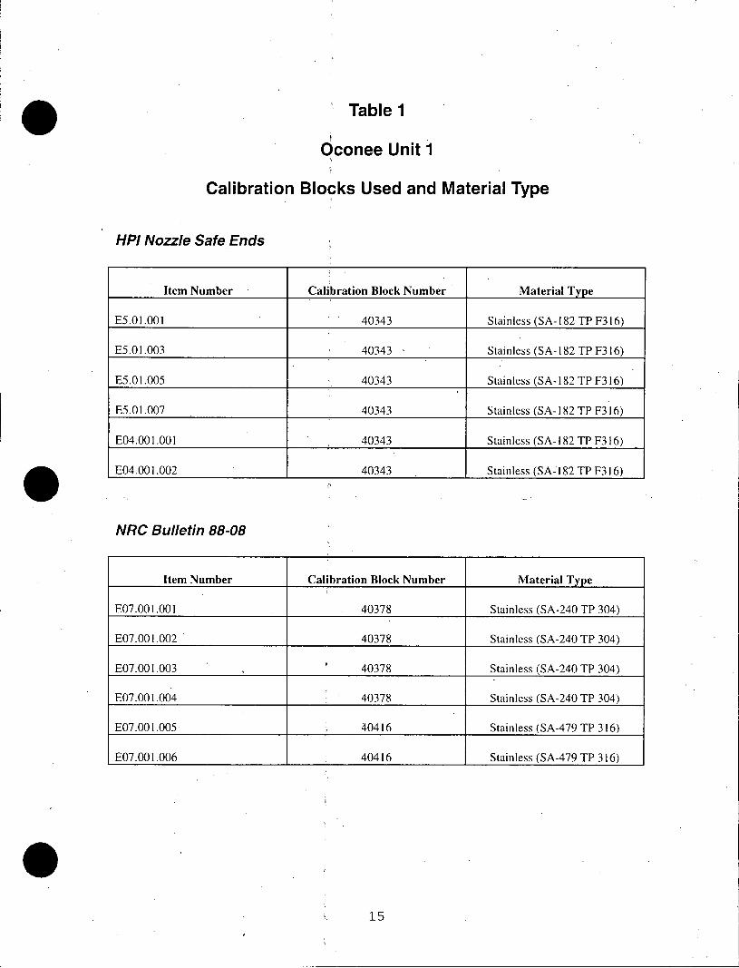
Table 1
Oconee Unit 1
Calibration Blocks Used and Material Type
HPI Nozzle Safe Ends
Item Number Calibration Block Number Material Type
E5.01.001 40343 Stainless (SA- 182 TP F316)
E5.01.003 40343 - Stainless (SA- 182 TP F316)
E5.01.005 40343 Stainless (SA- 182 TP F316)
E5.01.007 40343 Stainless (SA- 182 TP F316)
E04.001.001 40343 Stainless (SA- 182 TP F316)
E04.001.002 40343 Stainless (SA-l 82 TP F316)
NRC Bulletin 88-08
Item Number Calibration Block Number Material Type
E07.00 1.001 40378 Stainless (SA-240 TP 304)
E07.001.002 40378 Stainless (SA-240 TP 304)
E07.001.003 40378 Stainless (SA-240 TP 304)
E07.001.004 40378 Stainless (SA-240 TP 304)
E07.001.005 40416 Stainless (SA-479 TP 316)
E07.001.006 40416 Stainless (SA-479 TP 316)
15
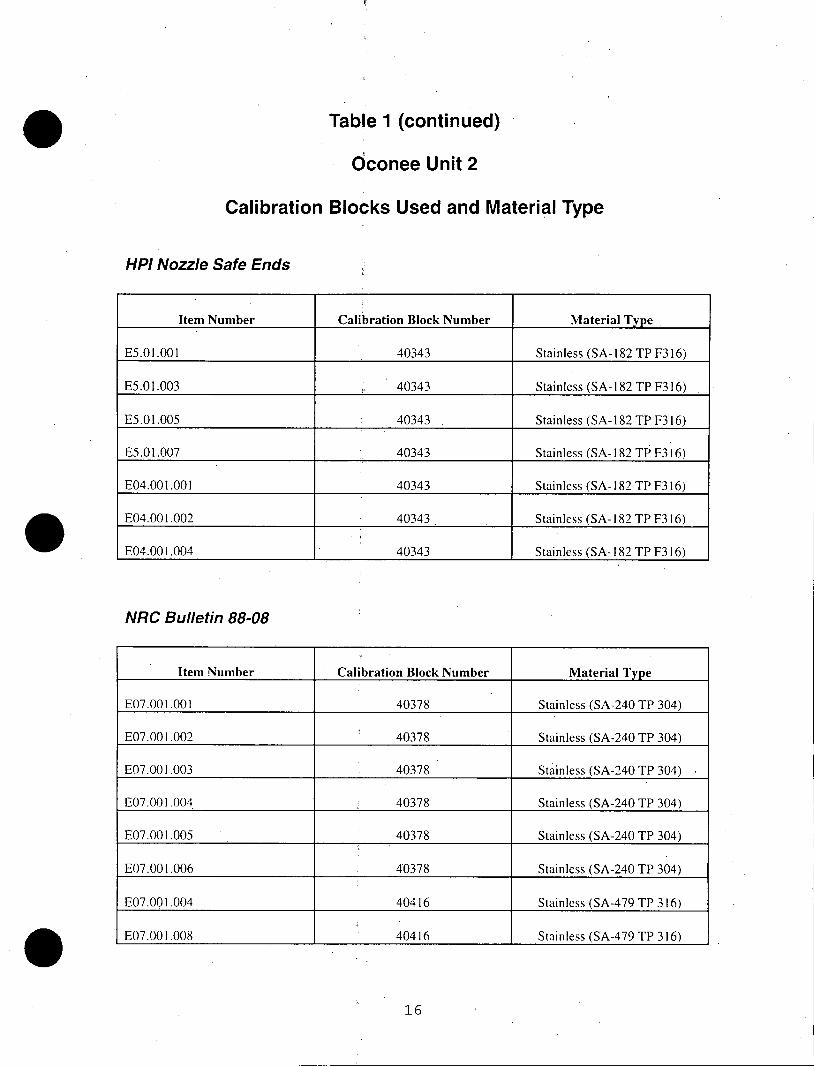
Table 1 (continued)
Oconee Unit 2
Calibration Blocks Used and Material Type
HPI Nozzle Safe Ends
Item Number Calibration Block Number Material Type
E5.01.001 40343 Stainless (SA-182 TP F316)
E5.01.003 40343 Stainless (SA-182 TP F316)
E5.01.005 40343 . Stainless (SA-182 TP F316)
E5.01.007 40343 Stainless (SA- 182 TP F316)
E04.001.001 40343 Stainless (SA-182 TP F316)
E04.001.002 40343 Stainless (SA-182 TP F316)
E04.001.004 40343 Stainless (SA-182 TP F316)
NRC Bulletin 88-08
Item Number Calibration Block Number Material Type
E07.001.001 40378 Stainless (SA-240 TP 304)
E07.001.002 40378 Stainless (SA-240 TP 304)
E07.001.003 40378 Stainless (SA-240 TP 304)
E07.001.004 40378 Stainless (SA-240 TP 304)
E07.001.005 40378 Stainless (SA-240 TP 304)
E07.001.006 40378 Stainless (SA-240 TP 304)
E07.001.004 40416 Stainless (SA-479 TP 316)
E07.001 .008 40416 Stainless (SA-479 TP 316)
16

Table 1 (continued)
Oconee Unit 3
Calibration Blocks Used and Material Type
HPI Nozzle Safe Ends
Item Number Calibration Block Number Material Type
E5.01.0013 40343 Stainless (SA-182 TP F316)
E5.01.015 40343 Stainless (SA-182 TP F316)
E5.01.017 40343 Stainless (SA- 182 TP F316)
E5.01.019 40343 Stainless (SA- 182 TP F316)
E04.001.001 40343 Stainless (SA- 182 TP F316)
E04.001.002 40343 Stainless (SA- 182 TP F316)
NRC Bulletin 88-08
Item Number Calibration Block Number Material Type
E07.001.001 40378 Stainless (SA-240 TP 304)
E07.001.002 40378 Stainless (SA-240 TP 304)
E07.001.003 40378 Stainless (SAL240 TP 304)
E07.001.004 40378 Stainless (SA-240 TP 304)
E07.001.005 40378 Stainless (SA-240 TP 304)
E07.001.006 40416 Stainless (SA-479 TP 316)
E07.001.007 40416 Stainless (SA-479 TP 316)
17
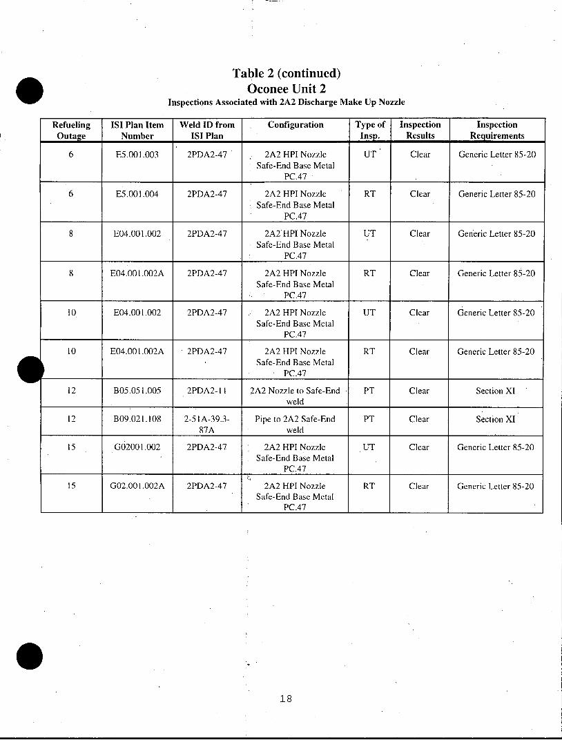
Table 2 (continued) Oconee Unit 2
Inspections Associated with 2A2 Discharge Make Up Nozzle
Refueling ISI Plan Item Weld ID from Configuration Type of Inspection Inspection Outage Number ISI Plan Insp. Results Requirements
6 E5.001.003 2PDA2-47 2A2 HPI Nozzle UT Clear Generic Letter 85-20 Safe-End Base Metal
PC.47
6 E5.001.004 2PDA2-47 2A2 HPI Nozzle RT Clear Generic Letter 85-20 Safe-End Base Metal
PC.47
8 E04.001.002 2PDA2-47 2A2 HPI Nozzle UT Clear Generic Letter 85-20 Safe-End Base Metal
PC.47
8 E04.001.002A 2PDA2-47 2A2 HPI Nozzle RT Clear Generic Letter 85-20 Safe-End Base Metal
PC.47
10 E04.001.002 2PDA2-47 2A2 HPI Nozzle UT Clear Generic Letter 85-20 Safe-End Base Metal
PC.47
10 E04.001.002A 2PDA2-47 2A2 HPI Nozzle RT Clear Generic Letter 85-20 Safe-End Base Metal
PC.47 I
12 B05.051.005 2PDA2-11 2A2 Nozzle to Safe-End PT Clear Section XI weld
12 B09.021.108 2-51A-39.3- Pipe to 2A2 Safe-End PT Clear Section XI 87A weld
15 G02001.002 2PDA2-47 2A2 HPI Nozzle UT Clear Generic Letter 85-20 Safe-End Base Metal
PC.47
15 G02.001.002A 2PDA2-47 2A2 HPI Nozzle RT Clear Generic Letter 85-20 Safe-End Base Metal
PC.47
18

Table 2 (continued) Oconee Unit 2
Inspections Associated with 2B1 Discharge HPI Nozzle
Refueling ISI Plan Item Weld ID from Configuration Type Inspection Inspection Outage Number ISI Plan of Results Requirements
6 E5.001.005 2PDB1-47 2B I HPI Nozzle Safe End UT Clear Generic Letter 85-20 Base Metal PC.47
6 E5.001.006 2PDB 1-47 2B 1 HPI Nozzle Safe End RT Clear Generic Letter 85-20 Base Metal PC.47 _
7 E04.001.003 2PDB1-47 2B1 HPI Nozzle Safe End RT Clear Generic Letter 85-20 Base Metal PC.47
8 E04.001.003 2PDB 1-47 2B I HPI Nozzle Safe End RT Clear Generic Letter 85-20 Base Metal PC.47
9 B05.051.008 2PDBI-l I 2BI Nozzle to Safe-End PT Clear Section XI weld
9 E04.001.003 2PDB1-47 2B1 HPI Nozzle Safe End RT Clear Generic Letter 85-20 Base Metal PC.47
10 B09.032.007 2PDBI-10 2B I HPI Nozzle to 2B I MT Clear Section XI RCP Discharge Piping
_ _ _(Branch Weld)
10 E04.001.003 2PDB 1-47 2B I HPI Nozzle Safe End RT Clear Generic Letter 85-20 Base Metal PC.47
10 E07.001.001 2-51A-39-90C Pipe to 2B1 Safe End UT Clear NRC Bulletin 88-08 weld & 1 inch base metal
10 E07.001.002 2-51A-39-90B Pipe to Pipe weld & 1 UT Clear NRC Bulletin 88-08 inch base metal
10 E07.001.003 2-51A-39-91 Pipe to Valve 2HP-153 UT Clear NRC Bulletin 88-08 weld & 1 inch base metal
10 E07.001.007 2PDB 1-1 2B I Nozzle to Safe-End UT Clear NRC Bulletin 88-08 weld & 1 inch base metal
II B09.021.114 2-51A-39.3-90C Pipe to 2B1 Safe-End PT Clear Section XI weld
12 E07.001.001 2-51A-39-90C Pipe to 2B1 Safe End UT Clear NRC Bulletin 88-08 weld & 1 inch base metal
12 E07.001.002 2-51A-39-90B Pipe to Pipe weld & 1 UT Clear NRC Bulletin 88-08 inch base metal
12 E07.001.003 2-51A-39-91 Pipe to Valve 2HP-153 UT Clear NRC Bulletin 88-08 weld & 1 inch base metal
19
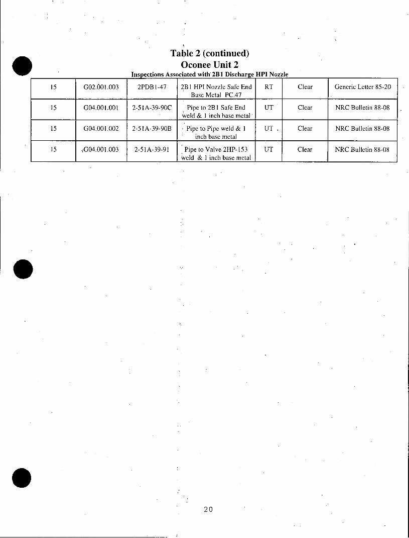
Table 2 (continued) Oconee Unit 2
Inspections Associated with 2B1 Discharge HPI Nozzle
15 G02.001.003 2PDB l-47 2B I HPI Nozzle Safe End RT Clear Generic Letter 85-20 Base Metal PC.47
15 G04.001.001 2-51A-39-90C Pipe to 2B1 Safe End UT Clear NRC Bulletin 88-08 weld & 1 inch base metal
15 G04.001.002 2-51A-39-90B Pipe to Pipe weld & 1 UT Clear NRC Bulletin 88-08 inch base metal
15 IG04.001.003 2-51A-39-91 Pipe to Valve 2HP-153 UT Clear NRC Bulletin 88-08 weld & 1 inch base metal
20

Table 2 (continued) Oconee Unit 2
Inspections Associated with 2B2 Discharge HPI Nozzle
Refueling ISI Plan Item Weld ID from Configuration Type Inspection Inspection Outage Number ISI Plan of Results Requirements
____________ _____________ _____ ________ ________ Insp. _______ _ _ _ _ _ _ _ _ _ _
6 E5.001.007 2PDB2-47 2B2 HPI Nozzle Safe End UT Clear Generic Letter 85-20 Base Metal PC.47
6 E5.001.008 2PDB2-47 2B2 HPI Nozzle Safe End RT Clear Generic Letter 85-20 Base Metal PC.47
8 E04.001.004 2PDB2-47 2B2 HPI Nozzle Safe End UT Clear Generic Letter 85-20 Base Metal PC.47
8 E04.001.004A 2PDB2-47 2B2 HPI Nozzle Safe End RT Clear Generic Letter 85-20 Base Metal PC.47
10 B09.032.008 2PDB2-10 2B2 HPI Nozzle to 2B2 MT Clear Section XI RCP Discharge Piping
(Branch Weld)
10 E04.001.004 2PDB2-47 2B2 HPI Nozzle Safe End UT Clear Generic Letter 85-20 Base Metal PC.47
10 E04.001.004A 2PDB2-47 2B2 HPI Nozzle Safe End RT Clear Generic Letter 85-20 Base Metal PC.47
10 E07.001.004 2-51A-39-92A Pipe to 2B2 Safe End UT Clear NRC Bulletin 88-08 weld & 1 inch base metal
10 E07.001.005 2-51A-39-92B Pipe to Pipe weld & i UT Clear NRC Bulletin 88-08 inch base metal
10 E07.001.006 2-51A-39-93 Pipe to Valve 2HP-152 UT Clear NRC Bulletin 88-08 weld & 1 inch base metal
10 E07.001.008 2PDB2-11 2B2 Nozzle to Safe-End UT Clear NRC Bulletin 88-08 weld & 1 inch base metal
11 B05.05 1.011 2PDB2-11 2B2 Nozzle to Safe-End PT Clear Section XI weld
12 B09.021.122 2-51A-39.3-92A Pipe to 2B2 Safe-End PT Clear Section XI .__weld
12 E07.001.004 2-51A-39-92A Pipe to 2B2 Safe End UT Clear NRC Bulletin 88-08 weld & 1 inch base metal
12 E07.001.005 2-51A-39-92B Pipe to Pipe weld & I UT Clear NRC Bulletin 88-08 inch base metal
12 E07.001.006 2-51A-39-93 Pipe to Valve 2HP-152 UT Clear NRC Bulletin 88-08 weld & 1 inch base metal .
21
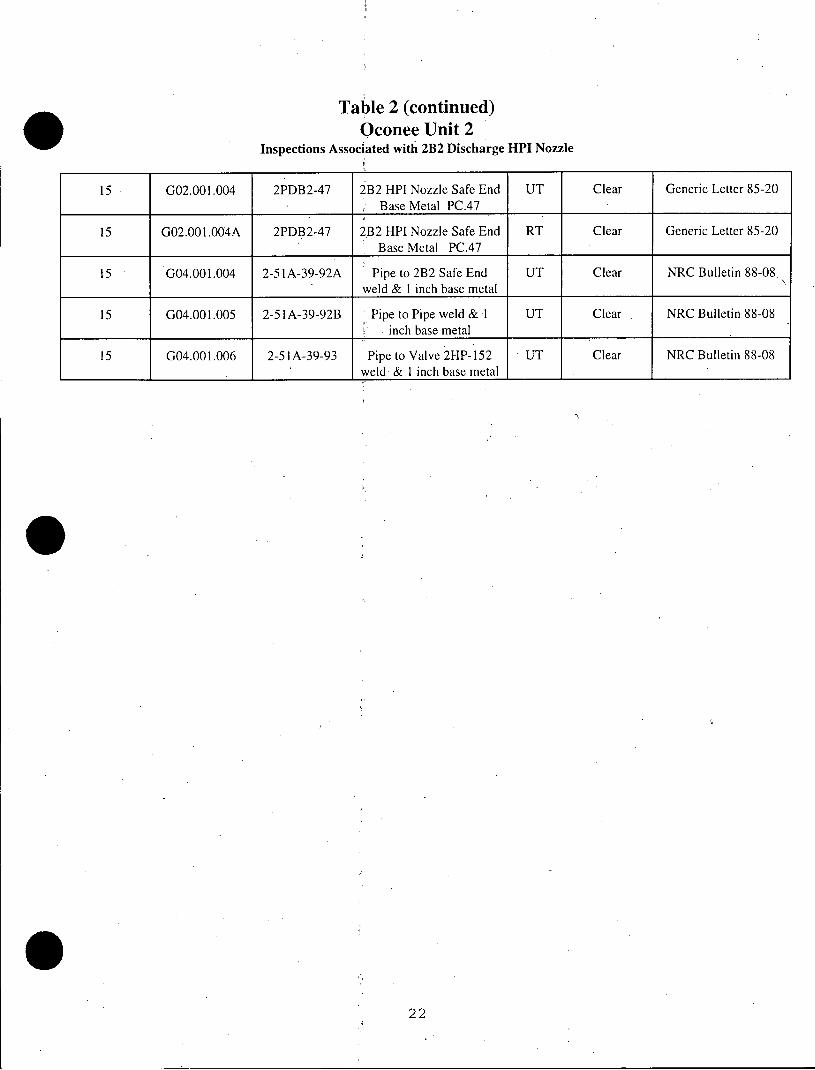
Table 2 (continued) Oconee Unit 2
Inspections Associated with 2B2 Discharge HPI Nozzle
15 G02.001.004 2PDB2-47 2B2 HPI Nozzle Safe End UT Clear Generic Letter 85-20 Base Metal PC.47
15 G02.001.004A 2PDB2-47 2B2 HPI Nozzle Safe End RT Clear Generic Letter 85-20 Base Metal PC.47
15 G04.001.004 2-51A-39-92A Pipe to 2B2 Safe End UT Clear NRC Bulletin 88-08. weld & I inch base metal
15 G04.001.005 2-51A-39-92B Pipe to Pipe weld & 1 UT Clear NRC Bulletin 88-08 inch base metal
15 G04.001.006 2-51A-39-93 Pipe to Valve 2HP-152 UT Clear NRC Bulletin 88-08 ___weld & I inch base metal
22
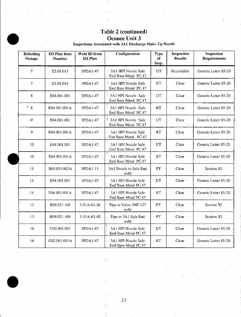
Table 2 (continued) Oconee Unit 3
Inspections Associated with 3A1 Discharge Make Up Nozzle
Refueling ISI Plan Item Weld ID from Configuration Type Inspection Inspection Outage Number ISI Plan of Results Requirements
Insp.
7 E5.01.013 3PDAl-47 3Al HPI Nozzle Safe UT Recordable Generic Letter 85-20 End Base Metal PC.47
7 E5.01.014 3PDAl-47 3Al HPI Nozzle Safe RT Clear Generic Letter 85-20 End Base Metal PC.47
8 E04.001.001 3PDAl-47 3Al HPI Nozzle Safe UT Clear Generic Letter 85-20 End Base Metal PC.47
8 E04.001.001A 3PDAl-47 3Al HPI Nozzle Safe RT Clear Generic Letter 85-20 End Base Metal PC.47
9 E04.001.001 3PDAl-47 3Al HPI Nozzle Safe UT Clear Generic Letter 85-20 End Base Metal PC.47 _
9 E04.001.001A 3PDAI-47 3Al HPI Nozzle Safe RT Clear Generic Letter 85-20 End Base Metal , PC.47
10 E04.001.001 3PDAI-47 3Al HPI Nozzle Safe UT Clear Generic Letter 85-20 End Base Metal PC.47
10 E04.001.001A 3PDAl-47 3Al HPI Nozzle Safe . RT Clear Generic Letter 85-20 End Base Metal PC.47 _
11 B05.051.002A 3PDAl-1 1 3Al Nozzle to Safe End PT Clear Section XI weld
11 E04.001.001 3PDAI-47 3Al HPI Nozzle Safe UT Clear Generic Letter 85-20 End Base Metal PC.47
11 E04.001.001A 3PDAI-47 3Al HPI Nozzle Safe RT Clear Generic Letter 85-20 End Base Metal PC.47
13 B09.021.108 3-51A-63-36 Pipe to Valve 3HP-127 PT Clear Section XI weld
13 B09.021.109 3-51A-63-40 Pipe to 3Al Safe End PT Clear Section XI weld
16 G02.001.001 3PDAI-47 3Al HPI Nozzle Safe UT Clear Generic Letter 85-20 End Base Metal PC.47
16 G02.001.001A 3PDAl-47 3Al HPI Nozzle Safe RT Clear Generic Letter 85-20 End Base Metal PC.47
23
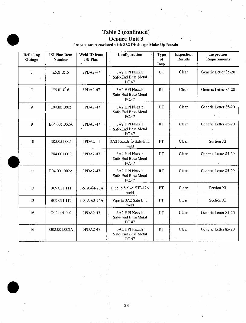
Table 2 (continued) Oconee Unit 3
Inspections Associated with 3A2 Discharge Make Up Nozzle
Refueling ISI Plan Item Weld ID from Configuration Type Inspection Inspection Outage Number ISI Plan of Results Requirements
Insp.
7 E5.01.015 3PDA2-47 3A2 HPI Nozzle UT Clear Generic Letter 85-20 Safe-End Base Metal
PC.47
7 E5.01.016 3PDA2-47 3A2 HPI Nozzle RT Clear Generic Letter 85-20 Safe-End Base Metal
PC.47
9 E04.001.002 3PDA2-47 3A2 HPI Nozzle UT Clear Generic Letter 85-20 Safe-End Base Metal
PC.47
9 E04.001.002A 3PDA2-47 3A2 HPI Nozzle RT Clear Generic Letter 85-20 Safe-End Base Metal
PC.47
10 B05.051.005 3PDA2-11 3A2 Nozzle to Safe-End PT Clear Section XI weld
I E04.001.002 3PDA2-47 3A2 HPI Nozzle UT Clear Generic Letter 85-20 Safe-End Base Metal
PC.47
11 E04.001.002A 3PDA2-47 3A2 HPI Nozzle RT Clear Generic Letter 85-20 Safe-End Base Metal
PC.47
13 B09.021.111 3-51A-64-23A Pipe to Valve 3HP-126 PT Clear Section XI weld
13 B09.021.112 3-51A-63-24A Pipe to 3A2 Safe End PT Clear Section XI weld
16 G02.001.002 3PDA2-47 3A2 HPI Nozzle UT Clear Generic Letter 85-20 Safe-End Base Metal
PC.47
16 G02.001.002A 3PDA2-47 3A2 HPI Nozzle RT Clear Generic Letter 85-20 Safe-End Base Metal
PC.47
24
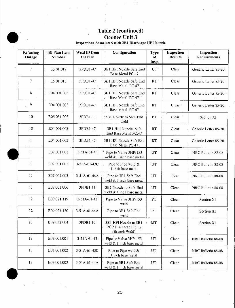
Table 2 (continued) Oconee Unit 3
Inspections Associated with 3B1 Discharge HPI Nozzle
Refueling ISI Plan Item Weld ID from Configuration Type Inspection Inspection Outage Number ISI Plan of Results Requirements
7 E5.01.017 3PDBl-47 3B1 HPI Nozzle Safe End UT Clear Generic Letter 85-20 Base Metal PC.47
7 E5.01.018 3PDB1-47 3B1 HPI Nozzle Safe End RT Clear Generic Letter 85-20 Base Metal PC.47
8 E04.001.003 3PDB1-47 3B I HPI Nozzle Safe End RT Clear Generic Letter 85-20 Base Metal PC.47
9 E04.001.003 3PDB 1-47 3B 1 HPI Nozzle Safe End RT Clear Generic Letter 85-20 Base Metal PC.47
10 B05.051.008 3PDBI-1 I 3B I Nozzle to Safe-End PT Clear Section XI weld
10 E04.001.003 3PDB 1-47 3B I HPI Nozzle Safe RT Clear Generic Letter 85-20 . End Base Metal PC.47
11 E04.001.003 3PDBl-47 3B I HPI Nozzle Safe End RT Clear Generic Letter 85-20 Base Metal PC.47
11 E07.001.001 3-51A-61-43 Pipe to Valve 3HP-153 UT Clear NRC Bulletin 88-08 weld & 1 inch base metal
11 E07.001.002 3-51A-61-43C Pipe to Pipe weld & UT Clear NRC Bulletin 88-08 1 inch base metal
11 E07.001.003 3-51A-61-44A Pipe to 3BI Safe End UT Clear NRC Bulletin 88-08 weld & 1 inch base metal
11 E07.001.006 3PDB 1-11 3B I Nozzle to Safe-End UT Clear NRC Bulletin 88-08 weld & _ inch base metal
12 B09.021.119 3-51A-61-43 Pipe to Valve 3HP-153 PT Clear Section XI weld
12 B09.021.120 3-51A-61-44A Pipe to 3B I Safe End PT Clear Section XI weld
13 B09.032.004 3PDBI-10 3B1 HPI Nozzle to 3B I MT Clear Section XI RCP Discharge Piping
(Branch Weld)
13 E07.001.001 3-51A-61-43 Pipe to Valve 3HP-153 UT Clear NRC Bulletin 88-08 weld & 1 inch base metal
13 E07.001.002 3-51A-61-43C Pipe to Pipe weld & UT Clear NRC Bulletin 88-08 1 inch base metal
13 E07.001.003 3-51A-61-44A Pipe to 3B1 Safe End UT Clear NRC Bulletin 88-08 weld & _ inch base metal
25
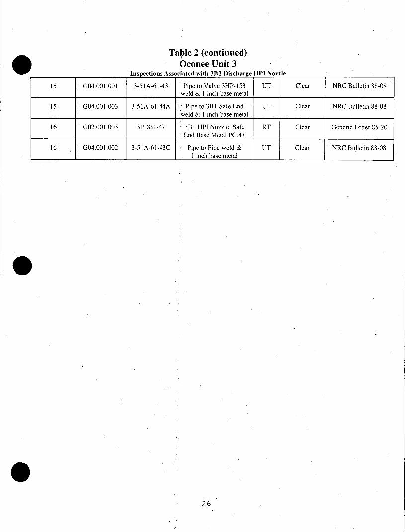
Table 2 (continued) Oconee Unit 3
Inspections Associated with 3B1 Discharge HPI Nozzle
15 G04.001.001 3-51A-61-43 Pipe to Valve 3HP-153 UT Clear NRC Bulletin 88-08 weld & 1 inch base metal
15 G04.001.003 3-51A-61-44A Pipe to 3B I Safe End UT Clear NRC Bulletin 88-08 weld & 1 inch base metal
16 G02.001.003 3PDB l-47 3B I HPI Nozzle Safe RT Clear Generic Letter 85-20 End Base Metal PC.47
16 G04.001.002 3-51A-61-43C Pipe to Pipe weld & UT Clear NRC Bulletin 88-08 1 inch base metal
26
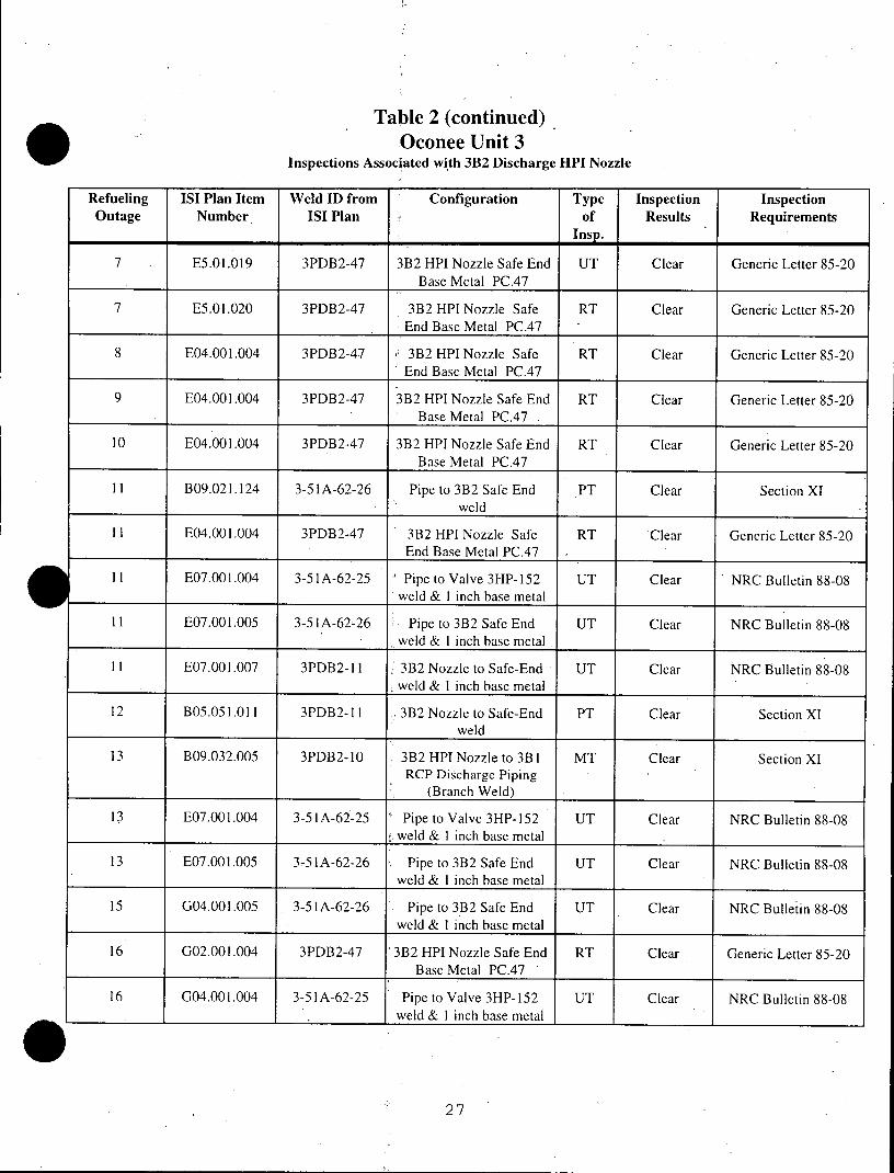
Table 2 (continued) Oconee Unit 3
Inspections Associated with 3B2 Discharge HPI Nozzle
Refueling ISI Plan Item Weld ID from Configuration Type Inspection Inspection Outage Number ISI Plan of Results Requirements
Insp.
7 E5.01.019 3PDB2-47 3B2 HPI Nozzle Safe End UT Clear Generic Letter 85-20 Base Metal PC.47
7 E5.01.020 3PDB2-47 3B2 HPI Nozzle Safe RT Clear Generic Letter 85-20 End Base Metal PC.47 _
8 E04.001.004 3PDB2-47 3B2 HPI Nozzle Safe RT Clear Generic Letter 85-20 End Base Metal PC.47
9 E04.001.004 3PDB2-47 3B2 HPI Nozzle Safe End RT Clear Generic Letter 85-20 Base Metal PC.47 .
10 E04.001.004 3PDB2-47 3B2 HPI Nozzle Safe End RT Clear Generic Letter 85-20 Base Metal PC.47
11 B09.021.124 3-51A-62-26 Pipe to 3B2 Safe End PT Clear Section XI weld
II E04.001.004 3PDB2-47 3B2 HPI Nozzle Safe RT Clear Generic Letter 85-20 End Base Metal PC.47
II E07.001.004 3-51A-62-25 Pipe to Valve 3HP-152 UT Clear NRC Bulletin 88-08 weld & 1 inch base metal
11 E07.001.005 3-51A-62-26 Pipe to 3B2 Safe End UT Clear NRC Bulletin 88-08 weld & 1 inch base metal
11 E07.001.007 3PDB2-11 3B2 Nozzle to Safe-End UT Clear NRC Bulletin 88-08 weld & 1 inch base metal
12 B05.051.011 3PDB2-11 3B2 Nozzle to Safe-End PT Clear Section XI weld
13 B09.032.005 3PDB2-10 3B2 HPI Nozzle to 3B1 MT Clear Section XI RCP Discharge Piping
(Branch Weld)
13 E07.001.004 3-51A-62-25 Pipe to Valve 3HP-152 UT Clear NRC Bulletin 88-08 weld & 1 inch base metal
13 E07.001.005 3-51A-62-26 Pipe to 3B2 Safe End UT Clear NRC Bulletin 88-08 weld & 1 inch base metal
15 G04.001.005 3-51A-62-26 Pipe to 3B2 Safe End UT Clear NRC Bulletin 88-08 weld & 1 inch base metal
16 G02.001.004 3PDB2-47 3B2 HPI Nozzle Safe End RT Clear Generic Letter 85-20 Base Metal PC.47
16 G04.001.004 3-51A-62-25 Pipe to Valve 3HP-152 UT Clear NRC Bulletin 88-08 __ _ _weld & 1 inch base metal
27
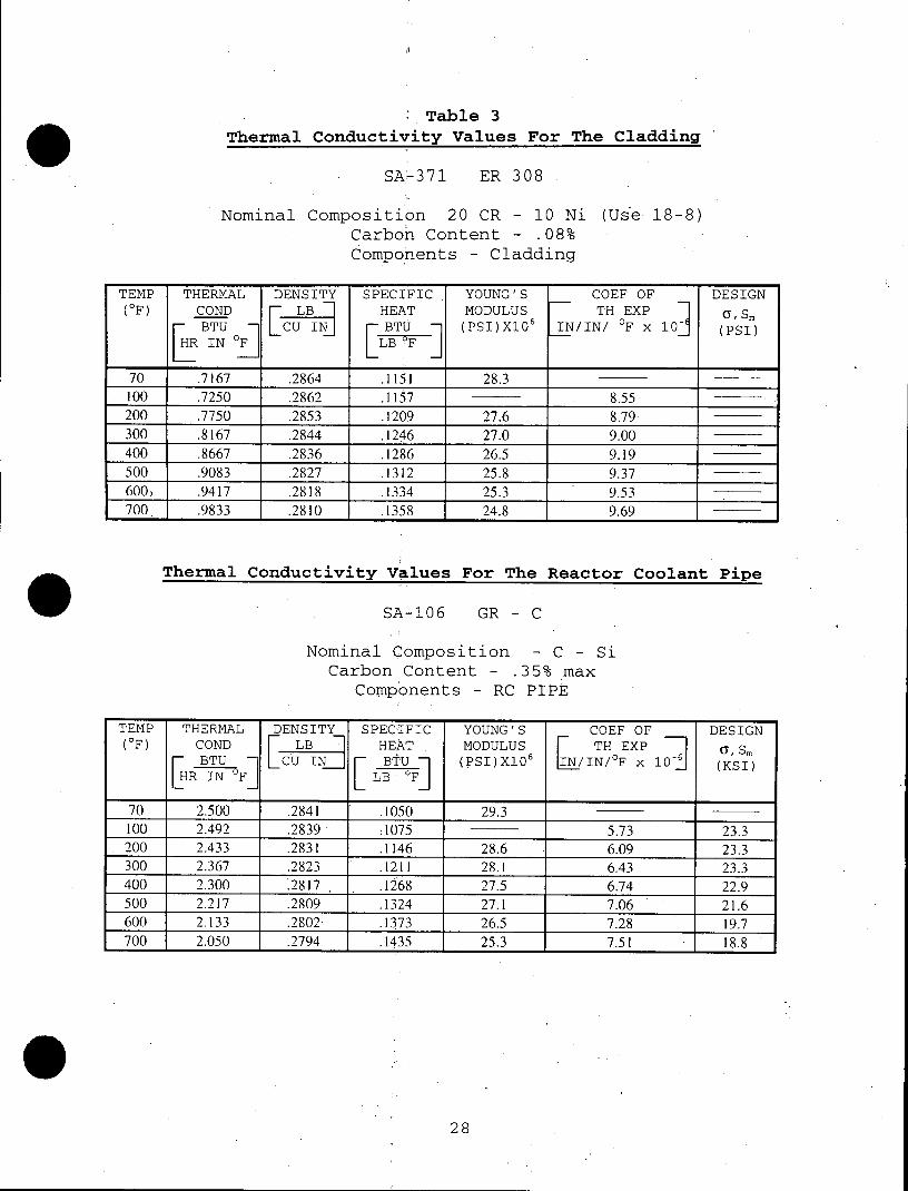
Table 3 Thermal Conductivity Values For The Cladding
SA-371 ER 308
Nominal Composition 20 CR - 10 Ni (Use 18-8) Carbon Content - .08%
Components - Cladding
TEMP THERMAL DENSITY SPECIFIC YOUNG'S COEF OF DESIGN (OF) COND LB HEAT MODULUS TH EXP GSm
BTU CU IN BTU (PSI)X106 IN/IN! OF x 10 (PSI) HR TU LB F]
70 .7167 .2864 .1151 28.3 -
100 .7250 .2862 .1157 8.55 200 .7750 .2853 .1209 27.6 8.79 300 .8167 .2844 .1246 27.0 9.00 400 .8667 .2836 .1286 26.5 9.19 _
500 .9083 .2827 .1312 25.8 9.37 600, .9417 .2818 .1334 25.3 9.53 700. .9833 .2810 .1358 24.8 9.69
Thermal Conductivity values For The Reactor Coolant Pipe
SA-106 GR - C
Nominal Composition - C - Si
Carbon Content - .35% max
Components - RC PIPE
TEMP THERMAL DENSITY SPECIFIC YOUNG'S COEF OF DESIGN (OF) COND r LB HEAT MODULUS TH EXP a, Sm
[ BTU LCU IN BTU (PSI)X10 IN/IN/oF X 10J (KSI) HR FLLB F OF]
70 2.500 .2841 .1050 29.3 100 2.492 .2839 .1075 5.73 23.3 200 2.433 .2831 .1146 28.6 6.09 23.3 300 2.367 .2823 .1211 28.1 6.43 23.3 400 2.300 .2817 . .1268 27.5 6.74 22.9 500 2.217 .2809 .1324 27.1 7.06 21.6 600 2.133 .2802 .1373 26.5 7.28 19.7 700 2.050 .2794 .1435 25.3 7.51 18.8
0 28
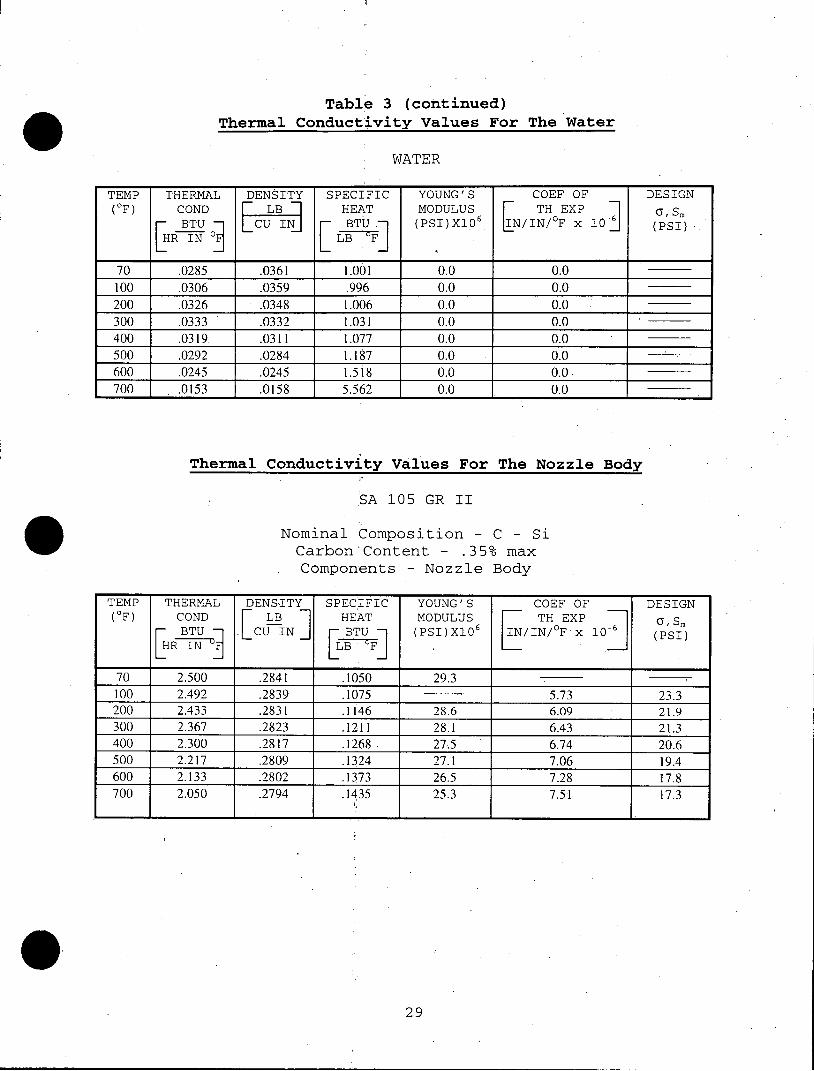
Table 3 (continued) Thermal Conductivity Values For The Water
WATER
TEMP THERMAL DENSITY SPECIFIC YOUNG'S COEF OF DESIGN (OF) COND LB HEAT MODULUS TH EXP0 S
BTU IN BTU (PSI)X106 LN/IN/oF X 10 (PSI)
70 .0285 .0361 1.001 0.0 0.0 100 .0306 .0359 .996 0.0 0.0 200 .0326 .0348 1.006 0.0 0.0 300 .0333 .0332 1.031 0.0 0.0 400 .0319. .0311 1.077 0.0 0.0
500 .0292 .0284 1.187 0.0 0.0
600 .0245 .0245 1.518 0.0 0.0 -
700 . .0153 .0158 5.562 0.0 0.0
Thermal Conductivity Values For The Nozzle Body
SA 105 GR II
Nominal Composition - C - Si
Carbon Content - .35% max
Components - Nozzle Body
TEMP THERMAL DENS-ITY SPECIFIC YOUNG'S COEF OF DESIGN (OF) COND LB HEAT MODULUS TH EXP as
LBTU I CU IN BTU (PSI)X10 IN/IN/oF x 10 (PSI)
70 2.500 .2841 .1050 29.3
100 2.492 .2839 .1075 ---- 5.73 23.3 200 2.433 .2831 .1146 28.6 6.09 21.9 300 2.367 .2823 .1211 28.1 6.43 21.3 400 2.300 .2817 .1268 27.5 6.74 20.6 500 2.217 .2809 .1324 27.1 7.06 19.4 600 2.133 .2802 .1373 26.5 7.28 17.8 700 2.050 .2794 .1435 25.3 7.51 17.3
29
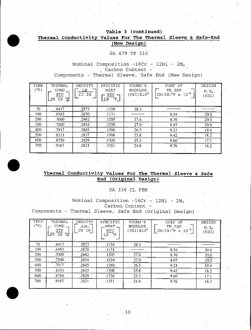
Table 3 (continued) Thermal Conductivity Values For The Thermal Sleeve & Safe-End
(New Design)
SA 479 TP 316
Nominal Composition -16Cr - 12Ni - 2Mo
Carbon Content Components - Thermal Sleeve, Safe End (New Design)
TEMP THERMAL DENSITY SPECIFIC YOUNG'S COEF OF DESIGN (OF) COND LB HEAT MODULUS 6 TH EXP a, Sm
BTU CU IN BTU (PSI)X106 I IN/0F x 10-' (KSI) [HR IN [ LB F
70. .6417 .2873 .1158 28.3
100 .6583 .2870 .1171 8.54 20.0 200 .7000 .2862 .1205 27.6 8.76 20.0 300 .7500 .2854 .1259 27.0 8.97 20.0 400 .7917 .2845 .1280 26.5 9.21 19.4 500 .8333 .2837 .1308 25.8 9.42 18.2 600 .8750 .2829 .1326 25.3 9.60 17.1 700 .9167 .2821 .1351 24.8 9.76 16.2
Thermal Conductivity Values For The Thermal Sleeve & Safe End (Original Design)
SA 336 CL F8M
NominalComposition -16Cr - 12Ni - 2Mo Carbon Content
Components - Thermal Sleeve, Safe End (Original Design)
TEMP THERMAL DENSITY SPECIFIC YOUNG'S COEF OF DESIGN (OF) COND LB-_ HEAT MODULUS TH EXP GSm
BTU LCU IN BTU (PSI)X10 IN/IN/ F x 10 (KSI) LR IN .d LB 0F
70 .6417 .2873 .1158 28.3
100 .6583 .2870 .1171 8.54 20.0 200 .7000 .2862 .1205 27.6 8.76 20.0 300 .7500 .2854 .1259 27.0 8.97 20.0 400 .7917 .2845 .1280 26.5 9.21 19.4 500 .8333 .2837 .1308 25.8 9.42 18.2 600 .8750 .2829 .1326 25.3 9.60 . 17.1 700 .9167 .2821 .1351 24.8 9.76 16.2
30