regulatoryonformation distribution s*1em (rids) … · accession nbr:8103020443 ducdate: 81/02/24...
TRANSCRIPT

REGULATORYONFORMATION DISTRIBUTION S*1EM (RIDS)
ACCESSION NBR:8103020443 DUCDATE: 81/02/24 NOTARIZED: NO DOCKET # FACIL:50-261 H, B. Robinson Planti, Unit 2, Carolina Power and Ligh 05000261 AUTH.NAME AUTHOR AFFILIATION
. UTLEY,E,E, Carolina Power & Light Co. RECIP.NAME) RECIPIENT AFFILIATION VARGASA. Operating.Reactors Branch 1
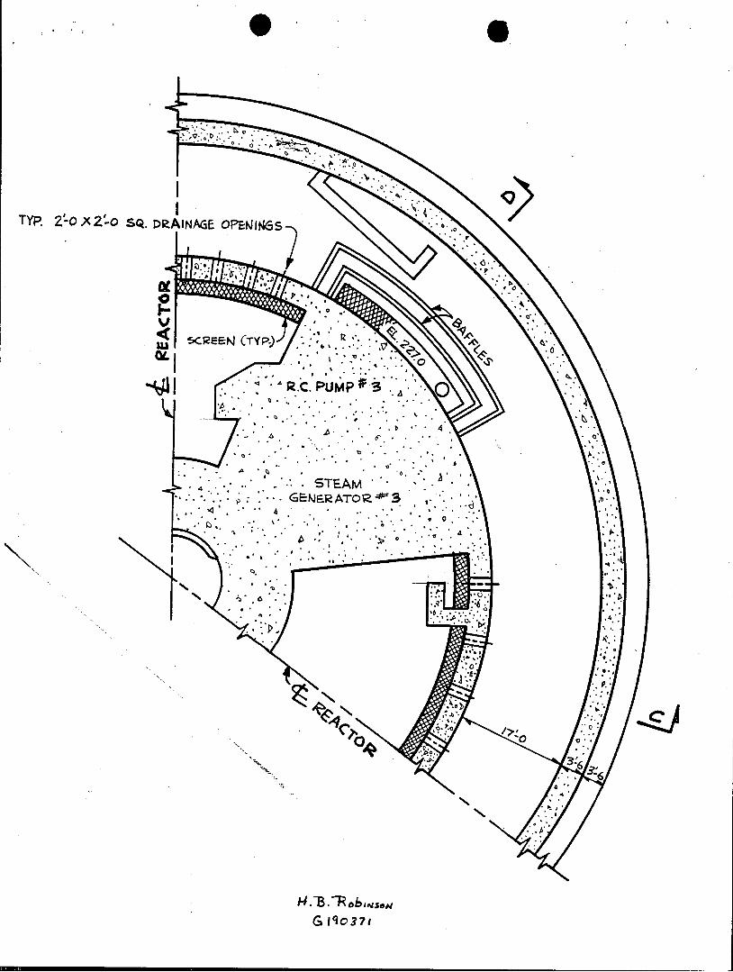
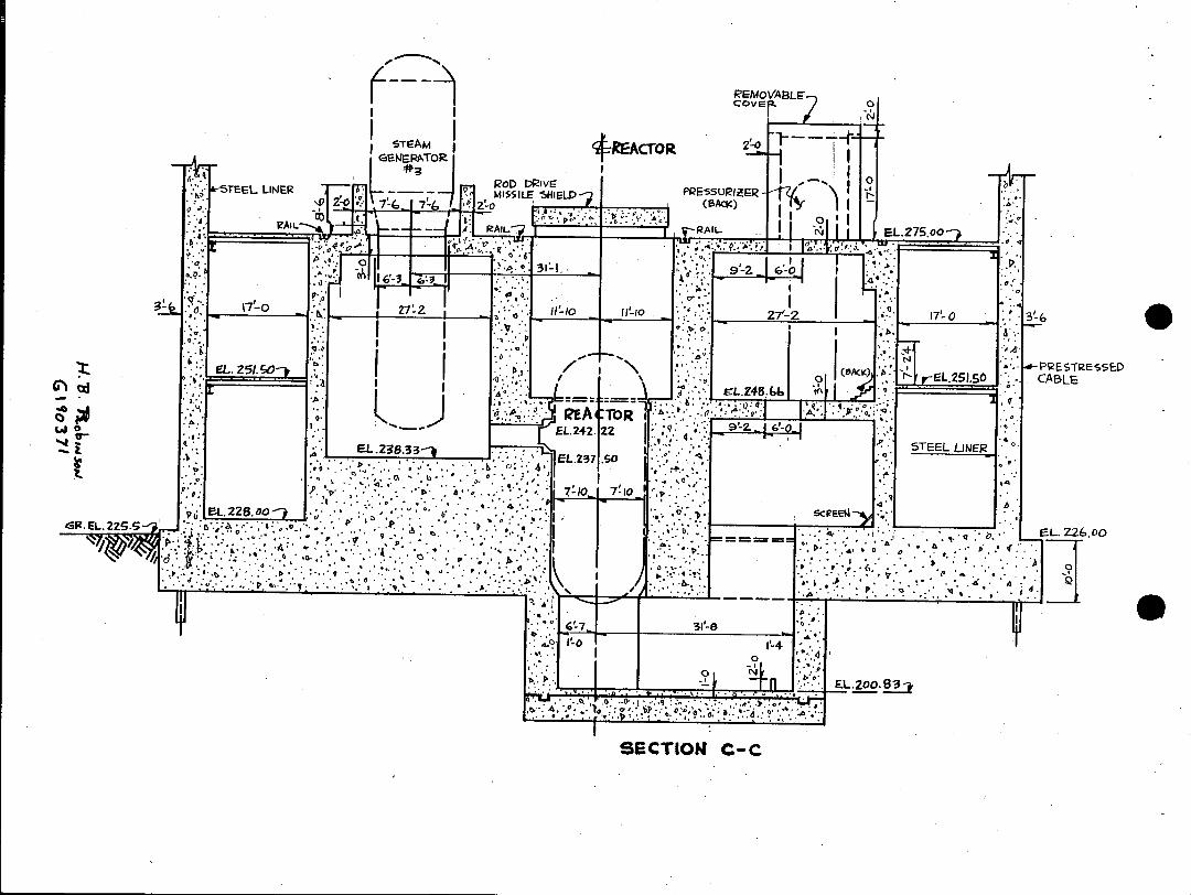
.SUBJECT: Responds to NRC 801031 request for info re containment sumps & insulation.Applicable portions of design drawings G-190267 & 190371 detailing RHR recirculation sump arrangement & associated piping encl.
DISTRIBUTION CODE: A001S COPIES RECEIVED:LTR j ENCL SIZE: TITLE: General Distribution for after!Issuance of Operating License
NOTES:
RECIPIENT COPIES RECIPIENT COPTES ID CODE/NAME LTTR ENCL ID CODE/NAME * LTTR ENCL
ACTION: VARGAS. 04 13 13
INTERNAL; D/DIRHUM FAC0 1 1 DIRDIV OF LIC 1 1 I&E1 06 2 2 NRC PDR 02 1 1 O11 1 0 OR ASSESS BR 10 1 0
G FILE 01 .1
EXTERNAL: ACRS 09 16 16 LPDR 03 1 1. NSIC 05. 1 1
TOTAL NUMBER OF COPIES REQUIRED: LTTR 39 ENCL 37

CP& Carolina Power)& Light Company
February 24, 1981
NG-3514(R) SERIAL NO.: NO-81-329
Office of Nuclear Reactor Regulation 4 ATTENTION: Mr. Steven A. Varga, Chief
Operating .Reactors Branch No. 1 United States Nuclear Regulatory Commission Washington, D. C. 20555
H. B. ROBINSON STEAM ELECTRIC PLANT UNIT NO. 2 DOCKET NO. 50-261 LICENSE NO. DPR-23
REQUEST FOR INFORMATION - CONTAINMENT SUMPS AND INSULATION FOR OPERATING REACTORS, TAP-43
Dear Mr. Varga:
This letter is in response to your request for information concerning containment sumps and insulation for operating reactors dated October 31, 1980. The reasons for our-delayed schedule in submitting this information were discussed with your.staff on February 6, 1981.
Enclosed for your use are the applicable portions of design drawing Nos. G-190267 and G-190371 detailing the residual heat removal (RHR) recirculation sump arrangement and associated piping. The basic insulation material used in containment during the construction phase was Unibestos block and pipe covering, manufactured by. Pittsburgh Corning Corporation at the Port Alleghaney, Pennsylvania plant. The density range of this material is .15-18 pounds per cubic foot. You will also find enclosed for your use the construction specification governing insulation material and its installation. A review of the piping and insulation list for parts of systems inside containment has determined Unibestos insulation was installed on piping in the following systems:
Chemical and Volume Control Reactor Coolant Safety Injection Component Cooling Water Service Water Feedwater Steam Generator Blowdown Main Steam Residual Heat Removal Sampling System
411 Fayetteville Street P. 0. Box 1551 * Raleigh, N. C. 27602
8103 020#411=
Unibestos insulated major components inside containment are as follows:
Steam Generators (3) Pressurizer Regenerative Heat Exchanger Reactor Coolant Pumps (3) Excess Letdown .Heat Exchanger
CP&L has estimated that approximately 6400 cubic feet of Unibestos was used in the initial insulation of piping and components within containment. Approximately 75 percent is in.the area within the missile barrier in the reactor coolant pump bays. These are gross estimates due to the fact that detailed construction records concerning the installation of insulation are not available. The present standard for new and replacement insulation for Q-List piping/components is Thermon-12.as manufactured by Johns-Manville Company.or equivalent, having a density of 13 pounds per cubic foot. Approximately 15 .percent of the originally installed insulation has been replaced with Thermon-12.
If you require additional information, please contact my staff.
Yours very truly,
E. E. Utley Executive Vice President
Power Supply and -Engineering & Construction
SWF/CSB/jc (2792) Enclosures
cc: Mr. J. D. Neighbors
4S
TYP 2-O X 2'-o SQ. DRAINAGE OPENINGS
~~ ARC. PU pW3
G 1 q0 3 7 1
REMOVABLE cove T
I I O~
STEAM RACTOR 2LO G2ERPATOR
ROD DRivE STEEL LINER MISSILE 5HIELD PRESSURIZER O D2'0 7'- (- 7-f. Z' o (BACK)
- . RAIL v-RAIL
7-0 4.0O -to
EL. 217 GO . (Wc 0 P T E
~LZ48,b r EL.2I.SOPPESTPESSED oL. -L.2c51.50 CABLE
EA -TOR EL ... EL.242. 22 .41:.
STEEL LINER
4 40
EL.EL. 2S.0
N. E::4~ :.. * ~ ::,Ki K ~* .4* ~ : L.2286oSCEo
.. .~ . o*
L6
S EL2O.83
SECTION C-C

R.=45!o To < . OF REACTOR.
k4 1-6 3'O 0 ~
I9.. 240.00 CONC. BLOCk
o. WALL
I CALE
EL.... ' . . 4 02~o
4..0
. su
ELZz.co . .
. . GR.EL.2
SECTION D-D H.13. RobswsoN
G I9 0 37I

*urchaser's Identification: hBASCO SPECIFICATION
1 RSCO PECFICAIONSpec No. CPL-R2-MI-1 HEAT INSULATION AND FREEZE PROTECTION
Issue Date: July 20, 1968
TABLE OF CONTENTS
PART I - HEAT INSULATION
Paragraph Description Page No..
1. Description............. ..... . . . . 1
2. General................. .... . . . 1
3. Standards................ .... . . . 1
4. Extent of Work & List of Drawings........ . . . . 1
5. Material.................. ... . . 4
6. Types and Thicknesses . . . . . . . . . . . . . . . . . 5
7. Scope of Piping . . . . ... .......... 6
8. Scope of Equipment............... . . . . 6
9. Scope of Non-Sweat Insulation. ......... . . . . 7
10. Workmanship & Application - Piping Insulation . . . . . 7A
11. Workmanship & Application - Pipe Covering..... . . . 8
12. Workmanship & Application - Piping Weatherproofing. . . 9
13. Workmanship & Application - Valves, Bends, Fittings Insulation & Covering.......... . . . . .. 9
14. Workmanship & Application - Equipment Insulation Covering & Weatherproofing ......... . . . 10
15. Anti-Freeze Protection. . .......... . . ..11
16. Samples .............. .......... . . 11
17. Guarantees........... ..... . . . . ..11
18. Nameplates.................... . . . 12
19. Thermal Movement........ ..... . . . .. . 13
20. Tests................. ... . . ..13
21. General Understanding & Agreement....... ... . . 13
22. Deviation from Standard............. . . . 13
23. Superintendence & Miscellaneous Requirements . . . . . 13
24. Inspection........... ...... . . ..14
i
C. Wurchaser's Identification: EBASCO SPECIFICATION
1EAT INSUlATION AND FREEZE PROTECTION Spec No. CPL-R2-MI-1 Issue Date: July 20, 1968
TABLE OF CONTENTS
PART II - FREEZE PROTECTION
Paragraph Description Page No.
25. General . . . . . . . . . . . . . . . *. . . ... . . . . 15
26. ;Extent of Work . . . . . . . . . . . . . . . . . . . . 15
27. System Classification . . . . . . . . . . . . . . . . . 15
28. Control System . . . . . . . . . . . . . . . . . . . . 16
29. Application of Cable & Insulation . . . . . . . . . .. . 16
30. Miscellaneous Piping to be Protected . . . . . . . . . 21
31. Preliminary Guide Freeze Protection by Electric Heating . . . . . . . . . . . . . . . . . . . . . . . 21

EBASO SECIFCATON chaser's Identification: EBASCO SPECIFICATION
HEAT INSULATION - PART I Spec No. CPL-R2-MI-1 Issue Date: July 20, 1968 R1: September 10, 1968
1. Purchaser -3basco Services Incorporated
Station - H B Robinson Plant - Unit No. 2
Location - Hartsville, South Carolina
Elevation - 225 feet above sea level
2.. The purpose of this specification is to designate the GENERAL
service requirements and essential particulars of all station heat
insulation, non-sweat and freeze protection with the exception of
the turbine generator and those items specifically excluded.
3. All heat insulation material-shall comply with applicable STANDARDS
codes (latest revision) of American Standards Association, American
Society for Testing Materials and American Society of Mechanical
Engineers., Also, construction shall comply with the state laws of
South Carolina and with local ordinance.
4. Seller shall furnish, deliver and apply in first class EXTENT OF
condition throughout, all heat insulating material, non-sweat pipe WORK
insulation, anti-freeze pipe insulation and its protective covering
for power plant piping nuclear steam supply system and equipment, in
cluding all valves and fittings as shown on Ebasco and/or Manufacturer's
equipment drawings listed in Paragraphs 4.5 and 8 and as outlined in the
following parts of this specification.
.1 Seller shall furnish all labor, transportation, apparatus
and tools required for the proper execution of the work described in
this specification.
.2 Seller shall unload and truck to job site and place all
materials in storage and shall assume full responsibility for damage
due to improper handling and by the weather elements.
Storage facilities adequately weatherproof ed shall be provided
by the seller.

chaser's Identification: EBASCO SPECIFICATION 2
HEAT INSULATION - PART I Spec No. CPL-R-MIIssue Date: July 20, 1968
4.3 Metal rods, clips or insulation supports attached to the EXTENT OF WORK
surfaces to be insulated where required shall be furnished and in- (Cont'd)
stalled by Purchaser.
.4 In general, all piping and equipment operating at temp
eratures above 1200 F shall be completely insulated and weather
protected except where the Purchaser specifically indicates that
insulation shall be omitted or is to be furnished by others.
.5 The following drawings marked up by the Seller indicate
the extent of heat insulation, non-sweat and freeze protection and
shall form a part of the order.
EBASCO DRAWINGS
Drawing Number Rev No. Title
B-190174 Piping and Insulation Standard B-190175 Valve and Specialty List G-190181 Gen Arrangement - Turbine Bldg
Ground Floor Plan G-190182 Gen Arrangement - Turbine Bldg
Mezzanine - Floor Plan
G-190183 Gen Arrangement - Turbine Bldg Operating Floor Plan
C-190184 Gen Arrangement - Turbine Bldg - Sections AA & BB
C-190186 Gen Arrangement - Reactor Bldg Plans - Sh 1
G-190187 Gen Arrangement - Reactor Bldg Plans - Sh 2
G-190188 Gen Arrangement - Reactor Bldg Sections C-190190 Gen Arrangement - Reactor Aux Bldg Plans 0-190191 Gen Arrangement - Reactor Aux Bldg Sections G-190192 Gen Arrangement - Fuel Handling Bldg &
Machine Shop - Plans
0-190193 Gen Arrangement - Fuel Handling Bldg & Machine Shop - Sections
0-190196 Flow Diagram - Main, Extraction and Aux Steam Systems
G-190197 Flow Diagram - Feedwater Condensate & Air Evacuation Systems
G-190198 Flow Diagram - Heater Drain & Vent Systems
G-190199 Flow Diagram - Service & Cooling Water Systems
G-190200 Flow Diagram - Plant.& Instr Air Systems
C-190202 Flow Diagram Fire & Make-up Water Systems
(;-190203 Flow Diagram Miscellaneous Systems - Sh 1 C-190204 Flow Diagram Miscellaneous Systems - Sh 2
-2-

SSPECIFn chaser's Identification: w EBASCO SPECIFICATION HEAT INSULATION - PART I ec No. CPL-R2-MI-1
Issue Date: July 20, 1968 R1: September 10, 1068
4.5 I,'basco Drawings (Cont'd) LXTNT OF WORK
Drawing Number Rev No. Title (Cont'd)
G-190206 Main Steam & Feedwater Piping Plan - Sheet 1
G-190207 Main Steam & Feedwater Piping Plan - Sheet 2
G-190208 Main Steam & Feedwater Piping - Sections
G-190210 Turbine and Extraction Steam Piping.Plan G-190211 Turbine and Extraction Steam Piping Plan
Sections G-190213 Condensate Piping Plan G-190214 Condensate Piping Sections C-190217 Heating Steam & Condensate Return Piping C-190220 Heater Drain and Vent Piping Plan C-190221 Heater Drain and Vent Piping Sections G-190223 Air Evacuation Piping C-190225 Reactor & Reactor Aux Bldgs Service & Cooling
Water Piping - Plan
C-190226 Reactor & Reactor Aux Bldgs Service & Cooling Water Piping Sections
C-190227 Turbine Bldg - Service & Cooling Water Piping Plan
G-190228 Turbine Bldg - Service & Cooling Water Piping Sections
G-190229 Fire Water Piping G-190233 Service & Instrument Air Piping - Plans
G-190236 Fuel Oil & Diesel Oil Piping Plans & Sections
G-190237 Lube Oil, Vapor Extractor & Misc Piping G-190238 Fuel Handling Bldg - Floor & Equip Drainage
and Embedded Piping 0-190232 Service & Instrument Air Piping 684-J-721- 0-190244 Flow Diagram Waste Disposal System
684-J-917- (-190245 Flow Diagram Waste Disposal System
541-F-056- 0-190247 Flow Diagram Sampling System
685-J-433 -f-190248 Flow Diagram Reactor Coolant System (Primary) 541-F-058 -0-190246 Flow Diagram Reactor Aux Coolant Sys - Resid. Heat Removal
684-1-731 -0-190249 Flow Diagram Reactor Aux Coolant System -Component Cool.
5111-F-059 -0-190250 Flow Diagram Reactor Aux Coolant System - Spent Fuel Pit Coo 684-J-753 -G-190251 Flow Diagram Chemical & Vol Cont Sys Sh 1
684-J-925 -0-190252 Flow Diagram Chemical & Vol Cont Sys Sh 2
541-F-55 -0-190253 Flow Diagram Chemical & Vol Cont Sys Sh 3
684-J-878 -0-190254 Flow Diagram - Safety Injection System G-190255 Waste Disposal Piping - Sh 1 C-190256 Waste Disposal Piping - Sh 2
C-190257 Waste Disposal Piping - Sh 3
C-190258 Waste Disposal Piping - Sh 4
-3-

t Purchaser's Identification: EBASCO SPECIFICATION
HEAT INSULATION - PART 1 Spec No. CPL-R2-MI-l Issue Date: July 20, 1968 R1: September 10, 1968 R2: February 27, 1969
4.5 Ebasco Drawings (Cont'd) EXTENT OF WORK
Drawing Number Rev No. Title (Cont'd)
C-190260 Primary & Demineralizer Water Piping G-190261 Penetration Pressurization System Piping 0-190262 Isolation Valve Seal Water System Piping C-190264 Nuclear Sampling System Piping C-190267 Residual Heat Removal System Piping G-190269 Primary Coolant Loop System Piping C-190270 Reactor Coolant System Piping G-190271 Reactor Component Coolant Sys Piping G-190272 Reactor Component Coolant Sys Piping - Plan C-190273 Reactor Component Coolant Sys Piping - Sections C-190274 Spent Fuel Pit Coolant System Piping G-190276 Chemical & Volume Control Sys Piping - Plan
Sheet 1 G-190277 Chemical & Volume Control Sys Piping - Plan
Sheet 2 G-190278 Chemical & Volume Control Sys Piping - Sections C-190279 Demineralizer Piping - Plan G-190280 Demineralizer Piping - Sections G-190281 Safety Injection System - Plan - Sh 1 G-190282 Safety Injection System - Plan - Sh 2 0-190283 Safety Injection System - Sections
5. Insulation class and thickness shall be as specified in MATERIAL
Ebasco Piping and Insulation Standard, Drawing No. B-190174 - R3
dated October 1, 1968.
All piping and equipment shall be insulated with a layer
of Unibestos, or equal.
The stainless steel piping and equipment insulation shall
meet the following requirements:
5.01 Only low leachable chloride insulation, silicate in
hibited against chloride stress corrosion of austenitic stainless
steel shall be used.
5.02 Seller shall submit for Ebasco approval the type of in
sulation material and shall include the following:
a - Trade name of product
1b - Name of Supplier -4-

Purchaser's Identification: EBASCO SPECIFICATION
HEAT INSULATION - PART 1 Spec No. CPL-R2-MI-1 Issue Date: July 20, 1968 R1: September 10, 1968 R2: February 27, 1969
5.02 (Cont'd) MATERIAL (Cont'd)
c - The form of the insulating material - pipe, block, board, blanket, cloth, felt, tape, adhesive or cement.
d - Applicable specifications to which materials conform.
e - Corrosion test data which confirms that the insulation product will not cause stress corrosion cracking when wetted.
5.03 All insulation materials shall meet the requirements of
the following stress corrosion test:
Knolls Atomic Power Test (H F Karnes, "The Corrosive
Potential of Wetted Thermal Insulation" presented at the AICHE 57th
National Meeting, September 25-29, 1965; Conf 650905-2; NSA 19:49949)
5.04 A Manufacturer's test report certifying that each lot or
batch of insulating materials will meet the stress corrosion test re
quirements in Paragraph 3, shall be submitted to Ebasco prior to in
stallation of material.
Piping and equipment shall also be weatherproofed with a
corrugated aluminum jacket of minimum thickness 0.016 in. with an in
tegral moisture barrier, except in reactor containment building where
white duck shall be used. VIMASCO WC-1 Mastic can be used on irregular
surfaces where aluminum jacketing is not practical.
.1 The insulating material and its protective covering
supplied and installed under this specification shall be of high
quality and shall conform to the following:
a -. Insulation Blocks
Unibestos insulation blocks of same material as piping insulation as manufactured by Pittsburgh Corning Corporation.
-4A -
chaser's Identification: EBASCO SPECIFICATION
HEAT INSULATION - PART 1 'ec No. CPL-R2-MI-1 Issue Date: July 20, 1968
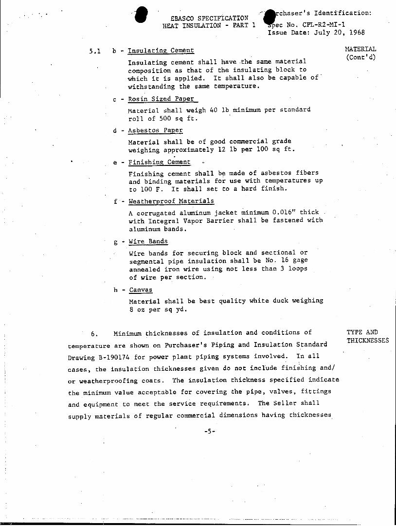
5.1 b - Insulating Cement MATERIAL (Cont'd)
Insulating cement shall have the same material composition as that of the insulating block to which it is applied. It shall also be capable of
withstanding the same temperature.
c - Rosin Sized Paper
Material shall weigh 40 lb minimum per standard roll of 500 sq ft.
d - Asbestos Paper
Material shall be of good commercial grade
weighing approximately 12 lb per 100 sq ft.
e - Finishing Cement
Finishing cement shall be made of asbestos fibers and binding materials for use with temperatures up to 100 F. It shall set to a hard finish.
f - Weatherproof Materials
A corrugated aluminum jacket minimum 0.016" thick with Integral Vapor Barrier shall be fastened with aluminum bands.
g - Wire Bands
Wire bands for securing block and sectional or segmental pipe insulation shall be No. 16 gage annealed iron wire using not less than 3 loops of wire per section.
h - Canvas
Material shall be best quality white duck weighing 8 oz per sq yd.
6. Minimum thicknesses of insulation and conditions of TYPE AND THICKNESSES
temperature are shown on Purchaser's Piping and Insulation Standard
Drawing B-190174 for power plant piping systems involved. In all
cases, the insulation thicknesses given do not include finishing and/
or weatherproofing coats. The insulation thickness specified indicate
the minimum value acceptable for covering the pipe, valves, fittings
and equipment to meet the service requirements. The .Seller shall
supply materials of regular commercial dimensions having thicknesses
-5-

4U chaser's Identification: EBASCO SPECIFICATION Spec No. CPL-R2-MI-1
HEAT INSULATION -PART 1 Issue Date: July 20, 1968
6. (Cont'd) TYPE AND
in closest accord; but not less than the specified minimum. The Seller THICKNESSES (Cont'd)
shall provide sufficient total thickness of heat insulation so that
the paper, canvas, or other surfacing or finishing material employed
will not be subjected to temperatures high enough to cause injury
to these materials or to discolor the lead and oil paint which may be
used thereon.
7. The power plant piping systems which include a complete SCOPE OF
outdoor installation subject to inclement weather and prevailing PIPING
winds, shall be adequately protected with suitable waterproof and
weather protected covering over insulation. A 1/2-inch thickness of
added insulation beyond the minimum specified in Purchaser's Piping
and Insulation Standard Dwg. No. B-190174, for retention of heat
is required for all outdoor piping systems and equipment.
.1. Insulation for personnel protection shall not be
included in the proposal but shall be furnished as directed later
by Purchaser's Construction Superintendent.
.2: All lines 2 inches and smaller shall be priced on a
unit cost.basis and furnished as directed later by Purchaser's
Construction Superintendent.
.3 All instrumentation, vent and drain lines shall be
insulated in the same manner as the connecting pipe, and up to
and including the first root valve.
8. Equipment indicated on Manufacturer's drawings tabulated SCOPE OF
below shall be insulated with block type insulation, or freeze pro- EQUIPMENT
tected listed in table below:
* An additional 1/2 inch heat insulation shall be added to the
minimum thickness listed below if equipment is located outdoors.
-6-

Purchaser's Identification:
EBASCO SPECIFICATION HEAT INSULATION - .PART I Spec No. CPL-R2-MI-1
Issue Date: July 20, 1968 Ri: September 10, 1968
Ebasco Mfg Dwg Operating Thickness
File No. Rev No. Title Qtv Temp. F In..
HEAT INSULATION
5379-36 R3 4432D98 HPi Heater 6A & 6B 2 442 2
5379-37 R2 4441D31 LP Heater SA & 5B 2 370 1-1/2
5379-44 R3 4445D23 LP Heater 4A & 4B 2 310 1-1/2
5379-45 R3 4445D15 LP Heater 3A & 3B 2 258 1-1/2
5379-46 R4 4441D59 LP Heater 2A & 2B 2 205 (1) 1-1/2
5379-53 R4 4441D58 LP Heater IA & 1B 2 171 (1) 1-1/2
5379-34 R4 4432D17 Moisture Separator Reheater 4 510 2
5379-787 R.2 FC-44096 Steam Driven Aux Feedwater Pump 1 510 2
5379-881 RI w-25-8A Heater Drain Pump 2 370 1-1/2 PICD86>2
5379-588 R3 FC-43570 Feedwater Pump 2 442 2
5379-1 R4 679J440/Shl Steam Generator -3 600 4-1/2
5379-244 R2 J618J742 Reactor Coolant Pumps 3 550 4
5379-1060 RO A04195-AOl Regenerative Heat Exch 1 550 4-1/2
5379-1057 RO V-8X20W86X1 Residual Heat Removal Pumps 2 350 2
5379-2 R3 4417D30 Pressurizer 1 650 5
Sketch Boron Injection Tank 1 170 1
5379-65 RO MC-1603, Boric Acid Blender 1 170 1
5379-785 RO DY-16352 Boric Acid Filter 1 170 1
5379-414 RI 685JO83 Boric Acid Tanks 1 170 1
5379-137 R2 684J838 Batching Tank 1 170 1
5379-224 RO A61673 Boric -Acid Transfer Pumps 2 170 (2) 1
5379-411 RO D-1503 Non-Regenerative Heat Exch 1 350 (3) 2
5379-412 R1 D-1519 Excess Letdown Heat Exch 1 550 (3) 2
5379-223 RO A-61670 Concentrates Holding Tank Pumps 2 170 (2) 1
5379-816 RO 51035 Concentrates Filter 1 170 1
5379-413 Ri D-1520 Residual Heat Exchangers 1 350 (3) 2
5379-136 R3 684J836 Concentrates Holding Tank 1 170 1
(1) Only portion exposed outside condenser neck (2) Heated enclosures (3) Bonnet only
-7-

Purchaser's Identification:
EBASCO SPECIFICATION HEAT INSULATION - PART I Spec No. CPL-R2-MI-1
Issue Date: July 20, 1968
Ri: September 10, 1968
Ebasco Mfg Dwg Operating Thickness
File No. Rev No. Title Qty Temp. 0 F In..
ANTI-FREEZE
5379-58 RI D140907 Condenser Vacuum Pump 2 110 (4) 1
9. Seller shall furnish, deliver and apply in first class SCOPE OF NON-SWEAT
condition throughout, non-sweat material, Foster's 60-24 cork INSULATING
filled mastic (or equal), a minimum coat 1/4 inch thick to be
applied by brush or trowel to pipe, valve, fitting or equipment.
10. Before insulating material is applied, all surfaces shall WORKMANSHII AND APPLI
be thoroughly cleaned of all foreign material such as scale, dirt CATION
and rust by use of steel wire brushes, steel scrapers or hanners PIPING IN
where necessary. No pipe shall be painted by the Seller before SULATION
application of insulating material, except as hereinafter noted
under Freeze Protection, paragraphs 29.1 and 29.6.
.1 All pipes up to and including 12 inches nominal diameter
shall be covered with molded form sectional pipe insulation made up
in 36-inch' sections having not more than two longitudinal joints. All
sectional insulation shall be carefully fitted to the pipes with side
and end joints butted tightly and securely wired in place with No. 16
gage annealed iron wire using not less than 3 loops of wire per section.
Where canvas jackets are specified for covering, all irregularities
in the insulation shall first be smoothed out with an application of
hard finish cement, sufficient only to provide a uniform, even surface
but not intended as a hard cement flnish coat. In applying double
layer insul.ation, the inner layer shall be securely wired in place with
16 gage annealed iron wire. The ends of all wire loops shall be firmly
twisted together with pliers, bent over and carefully pressed into the
surface of the insulation.
(4) 'feat Exchanger tank (up to water level) and circulating pump only.
-7A-

Purchaser's Identification: EBASCO SPECIFICATION
HEAT INSULATION - PART 1 Spec No. CPL-R2-MI-l Issue Date: July 20, 1968 Ri: September 10, 1968
10.2 Insulating material for piping over 12-inch nominal size, WORMANSHIP AND-APPLI
and all bends, shall be made of sectional (2 piece) blocks moulded CATION
to fit the circumference of the pipe. All segmental blocks shall PIPING INSULATION
be tightly butted together and wired in place with No. 16 gage (Cont'd) annealed 'iron wire in the manner described above for double layer
insulation. After being wired in place, the joints between the
segments shall be carefully tapped and rubbed close with a smooth
tool. Where two or more layers of insulating material are applied,
successive layers shall be laid to stagger both butt and longitud
inal joints with next adjoining layer. All sectional or segmental
block insulation having a total thickness, exclusive of specified
finish, greater than 2 inches shall be applied in two or more layers.
11. Heat insulation applied to main steam piping system WORKMIANSHIP AND. APPLIshall be covered with asbestos paper followed by a weatherproof CATION
corrugated aluminum jacket minimum 0.016 inches thick with vapor PIPE
barrier except for piping runs located within reactor containment COVERING
building.,
.1 All insulation applied to piping located outside of the
reactor containment building other than main steam piping shall be
protected with rosin-sized sheathing paper and corrugated aluminum
jacket minimum 0.016 inches with integral vapor barrier.
.2 Muslin furnished on sectional insulation shall be securely
and neatly pasted in place in all cases before rosin-sized sheathing
paper is applied.
-8-

*haser's Identification:
EBASCO SPECIFICATION HEAT INSULATION - PART I Se o P-2M
Issue Date: July 20, 1968
12. Heat insulation material applied to all piping except for WORKMANSHIP AND APPLI
bends and fittings, located outdoors shall be weather protected by a CATION. PIPING corrugated aluminum jacket, minimum 0.016 inches thick, with integral WEATHERPROOFIN(
vapor barrier.
.1 The aluminum jacket shall have lapped longitudinal joints
and shall be fastened with aluminum bands. Lapped joints for aluminum
jackets for pipe sizes up to 2 inches shall have an overlap of 1-1/2
inches, 2 inches overlap for pipe sizes up to 6 inches, 3-inch over
lap for pipe sizes up to 10 inches and 4-inch overlap for pipe sizes
over 10 inches. End joints of jackets shall also be lapped type,
sealed with a cold setting cement such as VIMASCO WC-1, product of
the Vimasco Corporation, or equal, one end of section of jacket pro
jecting over or under adjoining section of jacket, 2 inches for pipe
sizes up to 2 inches, 3 inches for pipe sizes up to 6 inches,
4 inches for pipe sizes over 6 inches. Longitudinal joints on hori
zontal runs of pipe shall be arranged so upper sheet overlap lower
sheet. End joints in vertical runs of pipes shall be arranged so
upper section of jacket overlaps lower section. Use of screws to
fasten aluminum jacket is prohibited and shall not be used unless
authorized by Purchaser.
.2 The weatherproof jacket used to cover the pipe insu
lation as outlined above shall not develop cracks or check marks
in service when subject to alternate periods of rain and sun, nor
tend to disintegrate or lose mechanical strength under the climatic
conditions generally prevailing in the locality of its installation.
13. All valves, bends and fittings shall be covered with WORKMANSHIP APPLICATION
molded block and plastic insulation of the thickness and type of VALVES, BENDS
material as used on adjacent pipes. On valves, bends and fittings & FITTINGS INSULATION &
3 inches and smaller, an all cement insulation may be used. Blocks COVERIN COVERING
shall be securely wired in place with No. 16 gage annealed iron wire and
all joints filled with plastic insulating cement of the same material
as the blocks. Insulation sections formed of plastic material shall be
thoroughly reinforced with galvanized wire mesh. Vimasco WC-1,
-9-
AIchaser's Identification: . EBASCO SPECIFICATION
HEAT INSULATION - PART I Spec No. CPL-R2-MI-1 Issue Date: July 20, 1968
13. (Cont'd) WORKMANSHIP APPLICATION
or equal, shall be applied on all valves and fittings (with exception VALVES, BENDS & FITTINGS
of bends and ells) in two or more layers and each layer of Vimasco INSULATION &
WC-1, or equal, shall be permitted to dry before the next is applied. COVERING (Cont'd)
A glass fabric embedded in the second coat of Vimasco WC-1 shall be
followed by a third coat of Vimasco WC-1, or equal. The outer surface
shall be troweled smooth. All valve bonnets shall be insulated up to
the stuffing boxes. The ells shall be fitted with aluminum sheet
metal jackets. The bends shall be also fitted with aluminum sheet
metal jacket(mitered sections where type for ells are not available).
The points at which the ell and bend jackets meet, the aluminum pipe
jackets and the seams in the jackets shall be finished in a manner
similar to that as described in Paragraph 12.1, Part I.
.1 Flange fitting insulation shall be solid built-up block
type securely wired in place with No. 16 gage annealed iron wire and
covered with plastic cement of the same material as the blocks.
Flange insulating material shall be applied after protecting
covering has been applied to adjacent pipe. Flange, including
valve bonnet flange, insulating blocks shall be constructed so that
they may be removed readily and replaced without damage to the
blocks, adjacent insulating material or its protective covering.
At flanged joints, the pipe insulation shall be tapered off at an
angle of approximately 45 degrees on both sides of the joint for
a length sufficient to permit removing flange bolts without damage
to the covering.
14. Block type insulating material shall be wired securely WORKMANSHIP AND APPLICATI
in place with No. 16 gage annealed iron wire or iron band and all EQUIPMENT
cracks or joints shall be filled solidly with plastic cement of same INSULATION COVERING A7D
material as insulation. One and one-half (1-1/2) inch mesh galvanized WEATHERPROOF
wire netting shall be stretched over insulating material and two coats
of hard asbestos cement applied, each coat being 1/4 inch thick.
-10-
irchaser's Identification: EBASCO SPECIFICATION Spec No. CPL-R2-MI-1
HEAT INSULATION - PART I se No e JulyR20,I 96 Issue Date: July 20, 1968
14. (Cont'd) WORKMANSHIP AND APPLICATI(
First coat shall be applied with a rough surface and allowed to dry EQUIPMENT
before second coat is applied. Second coat shall consist of two parts COVERIN
by weight :of hard finish, asbestos cement and one part of Portland WEATHERPROOFI (Cont'd)
Cement and shall be troweled to smooth, uniform surface and be o
finished neatly around all openings, heads, covers, plates, etc.
Rosin-sized paper can be substituted as an alternate for the two
coats of hard asbestos cement finish over the block type insulation.
Equipment (outdoor) insulation shall be provided with corrugated alum
inum jackets minimum 0.016 inches thick, with integral vapor barrier.
.1 Aluminum jacket joints shall be lapped and fastened
together with aluminum sheet metal bands. Inner surfaces of lapped
joints shall be coated with Vimasco WC-1, or equal, to provide a
sealed joint before fastening with bands.
.2 Insulation applied to bolted or screwed cover plates
or head of equipment and to manhole necks and flanged ends shall
be tapered-off toward the bolted flanges and stopped short so that
bolts, screws, heads, covers or plates may be removed without
damage to the insulation or covering.
3 Rain shields over pipe penetrating concrete decks
shall be furnished later as directed by Purchaser's Construction
Superintendent and shall be priced on a unit cost basis.
15. Seller shall furnish anti-freeze protection in ac- ANTI-FREEZE PROTECTION
cordance with Purchaser's Specification CPL-R2-MI-1, Part II.
16. Seller shall furnish full size samples of material SAMPLES
upon Purchaser's request.
17. In addition to guarantees given by Seller, as required GUARANTEES
by Purchaser's General Conditions attached hereto, the Seller shall
guarantee the following:
.1 Heat losses and efficiencies shall be within 10 percent
of those specified by "85% Magnesia Insulation Manual" latest edition.

Orchaser's Identification: EBASCOSpec No. CPL-R2-MI-1
HEAT INSULATION - PART ISe o P-2MIssue Date: July 20, 1968
17.2 In the event that Seller's material does not meet the GUARANTEES (Cont'd)
heat transfer loss guarantee, liability under such a guarantee shall
include, among other items, application by Seller free of all cost to
the Purchaser of sufficient insulating material over original insulation
to reduce heat loss to guaranteed amount. In this latter case, Seller
shall remove the insulating material already applied and reinsulate the
piping or equipment with insulation that will meet the guarantee.
.3 Seller shall also guarantee the entire job as to the
quality of material and workmanship for a period of two years from
date of application.
18. Equipment nameplates shall be removed and reinstalled NAMEPLATES
by Seller on outside of covered insulated surface in a secure
manner satisfactory to the Purchaser.
19. Suitable and adequate means,acceptable to the Purchaser, THERMAL
shall be provided as required in all insulation for effects of changes MOVENT
in temperature of the insulated surface and of any metal used in
supporting the insulation. Insulation, on surfaces where appreciable
thermal movement may be expected, shall be applied in a manner which
will avoid the occurrence of breaking or telescoping of insulating
material due to alternate periods of expansion and contraction.
Expansion:joints in the insulation of high 'temperature pipe systems
shall not be spaced less than 15 feet apart. The proposed methods
for accommodating thermal expansion on vertical risers as well as
horizontal runs shall be submitted to the Purchaser for approval.
20. Tests to determine heat conductivity shall be made by TESTS
the "Electrical Method" as described in detail in ASME Transactions
Vol. No. 37 or by such other methods as mutually agreed upon between
Purchaser and Seller. Before performance of such tests, Purchaser
and Seller shall agree upon: -12-
Erchaser's Identification: EBASCO SPECIFICATIONW
HEAT INSULATION - PART I Spec No. CPL-R2-MI-l Issue Date: July 20, 1968
20. (Cont'd) TESTS (Cont'd)
a - General procedure for carrying ,out tests.
b - Number of tests to be performed.
c - Method of averaging such tests.
d - Necessity of check tests and their bearing on normal tests.
21. This specification, together with Purchaser's and GENERAL UNDERSTANDING
equipment Manufacturer's drawings herein enumerated are to be taken UNDEANDING AND AGREEN'T
together, and any work specified or indicated and any such work as
can reasonably be inferred therefrom as necessary to complete the
application of insulating material and protective covering to each
and any of the various piping systems and equipment specified is
included unless specifically stated to the contrary, and shall be
performed by Seller in satisfactory fulfillment of this specification.
22. In general, the Seller shall follow methods and technical DEVIATION
data, as outlined in this specification. However, the Seller.may, SDM STANDA.RDS*
upon approval of the Purchaser, deviate from type of material,
thicknesses or procedure set herein if Seller can show such action
will better either the efficiency of insulation, workmanship or
economy of insulation without the improvement of one being seriously
detrimental to the other.
23. Seller shall furnish a competent superintendent exper- SUPERINTENDENC AND MISCELLAN
ienced in this class of work who shall oversee the work and keep a EOUS REQUIRE
running inventory of materials available and required to complete the MENTS
work in order that, at all times, sufficient material will be available.
All unused material and loose scaffolding will be removed and the
premises left in a condition satisfactory to Purchaser's Superin
tendent before leaving the site each day; when not done, Purchaser'.s
Superintendent will provide clean-up service against Contractor's
account. After the work covered by this specification has been
completed,all rubbish and debris resulting from such work shall be
removed and the premises left in a condition satisfactory to the
Purchaser. -13-

EBASC SPEIFI~ION haser's Identification: EBASCO SPECIFICATION NoCP-2M1
HEAT INSUTLATION -PART I No. CPL-R2-Iil Issue Date: July 20, 1968
24. The Purchaser's Inspector shall have the right to INSPECTION
examine all work and material at the factory or the site, and
any material found to be defective, or which does not meet the
requirements of this specification, shall be replaced by the Seller
at his own expense. Such inspection, however, shall not relieve the
Seller from full responsibility for the quality and correctness of
his materials and work.
-14-

EBASCO SPECIFICATION *1prchaser's Identification:
FREEZE PROTECTION - PART IISpec Mo. CPL-R2-MI-1 Issue Date: July 20, 1968
25. The purpose of this specification is to provide for a GENERAL
satisfactory installation for protection of certain piping, equipment,
controls and accessories against possible freezing when exposed to
outdoor winter weather conditions. It is contemplated that the
feedwater and condensate piping and including lines through which
flow can be maintained at all times or which can be drained, will
not be protected beyond the regular heat insulation except at
specific locations.
26. Seller shall furnish, deliver and apply in first class EXTENT OF
condition throughout, anti-freeze pipe insulation and its protective WORK
covering on -all exposed cooling and service water piping. All ex
posed and accessible piping at circulating water pump intake structure,
sample and equipment bearing cooling water supply and return shall be
protected with anti-freeze materials in accordance with Piping &
Insulation. Standard Drawing No. B-190174, and Paragraph 31 - Freeze
Protection by Electric Heating.
27. The anti-freeze material for the station is divided into SYSTEM CLASSIFICATIO
two piping systems:
a - Cold pipe system.
b - Hot and/or Cold Insulated Pipe System.
.1 The cold pipe system such as: (a) Cold Water Piping,
(b) Compressed Air Piping and all operating pipe lines which never
exceed 120 F; all pipe systems designated as "cold pipes" are to be
freeze protected as hereinafter specified.
.2 The hot and/or cold insulated pipe designation applies to
all lines requiring protection which may be either hot or cold for
normal operation and under this classification, all of the piping is
to receive the regular heat insulation materials as specified in the
Piping and Insulation Standard Drawing B-190174 and, in addition,
heating cable for freeze protection.
-15-
haser's Identification: EBASCO SPECIFICATION No P-2Ml
FREEZE PROTECTION - PART II Issue Date: July 20, 1968
28. The freeze protection circuits for those piping systems CONTROL
and tanks subject to freezing temperature during normal operation SYSTEM
will be protected automatically by energizing Purchaser's thermostats
arranged in parallel electrical circuits. The piping systems and tanks
subject to freezing during plant shut-down only will be protected by
a manual switch located at a winterizing control panel.
Location of thermostats will be as follows:
Thermostat No. Location of Thermostat
A On Col (later) at approx El (later) ft
B On Col (later) at approx El (later) ft
29. Heating cable application for both "Cold Pipe" and APPLICATION OF CABLE AND
"Hot and/or Cold Insulated Pipe" lines shall be in accordance with INSULATION
the following schedule:
a - Type MI Heating Cable Furnished & Applied by Purchaser
b - Type MI Feeder Cable Furnished & Applied by Purchaser
c - Flexible Mineral Felt, Furnished & Applied or equal by Seller
d - Sheet Aluminum minimum Furnished & Applied 0.016" thickness with by Seller integral Vapor Barrier
e - Paper Masking Tape - Furnished & Applied 1" width by Purchaser
f - Vimasco WC-1, or equal Furnished & Applied by Seller
g - Aluminum Foil 0.004" Furnished & Applied thick by Seller
h - Zinc rich paint on pipe Furnished & Applied surfaces by Purchaser
The above materials to be applied as follls:
-16-

EBASCO SPECIFICATION I chaser's Identification: FREEZE PROTECTION - PART II . CPL-R2-MI-l
Issue Date: July 20, 1968
29.1 Cold Pipe System APPLICATION OF CABLE AND
One (1) coat of Debanode or Galvanox zinc-rich paint, or INSULATION
equal, shall be applied by Purchaser to all bare cold water lines in (Cont'd)
accordance with Ebasco Coating Guide CP-21, Rev 1, prior to the
application of heating cable and/or insulation.
.2 Heating cables shall be selected by Purchaser. When
tubing is also run in bundle with one or more pipes, the over-all
diameter of the bundle shall determine the quantity of heating cable
and insulating materials to be applied using nearest outside diameter
for pipe size.
.3 Fiberglas with vapor barrier, 1 inch thick insulation
with notch provided for heating cable*, shall be applied and
fastened in place with monel wire for pipe sizes up to 6 inches.
For 8 inch pipe size and over, 1-1/2 inch thick fiberglas with
vapor barrier insulation having notch provided for heating cable*,
shall be furnished,
.4 Corrugated aluminum covering with integral vapor
barrier shall be wrapped over the fiberglas insulation with the
longitudinal seam or joint made by overlapping 4 inches or less as
described in Part I, Par. 12.
.5 The aluminum jacket shall be installed as outlined in
Part I, Par. 12.
For all hot and/or cold insulated pipes which are
continuously and intermittently hot and/or cold during normal
plant operation.
This section deals with application of heating cable to
6 inches and smaller piping operating at less than 500 F.
* Notch shall be provided in all anti-freeze insulation for heating cable where applicable. Oversize insulation is acceptable only on instrumentation piping and tubing. The cost of notching the insulation or the use of oversize insulation shall be included in the quoted price.
-17-
* rchaser's IdentificatioI: EBASCO SPECIFICATION Spec No. CPL-R2-MI-l
FREEZE PROTECTION - PART II Issue Date: July 20, 1968
29.13 To prevent progressive deterioration of the heating APPLICATION OF CABLE AND
cable copper sheath, one layer of thermal insulation must be applied INSULAN INSULATION
to the piping before the heating cable is applied. Since the area .(Cont'd)
protected is that area which is at the radius on which the heating
cable is focated, the outside diameter of the insulation beneath the
heating cable determines the area of the protected surface for the
purpose of determining heating requirements.
.14 The heating cable shall be attached with one inch paper
masking tape to hold it firmly in place until remainder of insulation
and jacketing is complete.
.15 For all pipes and/or tanks with thermal insulation under
the heating cable, one wrap of 0.004 in. embossed aluminum foil is
required over the heating cable. The aluminum foil shall be applied
in 3 ft sections held in place with a tinsmith's "lock" which can be
made by hand without tools. This foil is available in rolls three feet
wide containing approximately 360 linear feet.. Joints between
sections should be wired or taped unless remainder of thermal in
sulation is to be applied the same day.
.16 Thermal insulation for piping over 500 F shall be applied
as specified in Part I except that the outer layer of thermal in
sulation used on the inner.layer of thermal insulation as required by
Part II, paragraph 29.13, shall be Fiberglas with vapor barrier in
sulation with the thickness being based on the outer diameter of the
high temperature thermal insulation.
.17 General Instruction On Accessories
Fiberglas with vapor barrier insulation 1 inch thick
shall be used for bare pipe sizes up to and including 6 in. pipe size
and 1-1/2 inch thick fiberglas with vapor barrier insulation for
8-inch pipe size and larger. Where Fiberglas with vapor barrier in
sulation is used for the outer layer of normally insulated pipe as
specified in Paragraph 29.13, the thickness of fiberglas insulation
shall be selected to agree with Part I.
-19-
*chaser's Identification: EBASCO SPECIFICATION
FREEZE PROTECTION - PART II No. CPL-R2-MI-1 Issue Date: July 20, 1968
29.6 Exterior surfaces of bare black iron pipe which will be APPLICATION OF CABLE AND
intermittently hot during normal operation shall be painted with one INSULATION
coat of zinc-rich paint as in Paragraph 29.1 above. In addition, (Cont'd)
since galvanic action with the copper sheath will occur in the presence
of moisture, it will be necessary to minimize this action. Glass
impregnated cloth tape (Scotch Electrical Tape Number 27, or equivalent)
shall be applied to the heating cable used for all pipe, hot or cold.
One inch wide tape applied to cable half lapped at factory will
protect the cable satisfactorily.
.7 The heating cable shall be attached to the outer pipe or
tank surface with 1-inch paper masking tape to hold it firmly in place
until thermal insulation and jacketing is complete.
.8 Heating cable shall be applied and run straight along
the pipe line. No weather resistant paint shall be applied to the
bare pipe (except for cold pipes).
.9 Fiberglas insulation shall be applied in accordance with
Part II, Paragraph 29.3.
.10 Aluminum covering with integral vaporseal barrier shall
be applied over the insulation material.
This section deals with application of heating cable
to 8 inch and larger piping operated at less than 500 F.
For piping 8 inch nominal size and larger, multiple
straight runs of heating cable are required equally
spaced over circumference of protected area.
.11 Application of heating cable shall be.the same as
described in Part II, Paragraph 29.6 and 29.7, above.
.12 Thermal insulation shall be applied as described in
Part II, Paragraphs 29.3 and 29.4.
This section deals with application of heating cable
to.piping which regularly exceeds 500 F.
-18-

'A rchaser's Identification: EBASCO SPECIFICATION
FREEZE PROTECTION - PART II spe No. l20, 1968 Issue Date: July 20, 1968
29'.18 Monel wire shall be used to hold the insulation firmly APPLICATION OF CABLE AND
in place. Two wires per section up to 6 inch pipe size and three INSULATION
wires per section above 6 inch pipe size. (Cont'd)
.19 The longitudinal flap of the Fiberglas with vapor
barrier insulation shall be attached to the pipe insulation by
applying a thin brush coat of Vimasco WC-1, or equal. At the butt
joints, a two-inch wide brush coat of Vimasco WC-1, or equal, will
be applied around the circumference of the pipe insulation overlapping
the joint 1 inch on adjoining sections embedding the fiberglas with
vapor barrier insulation over the butt joint.
.20 Valves, fittings and other accessories installed in
the pipe line shall be insulated as follows for freeze protection:
.21 Valves, fittings and other accessories installed in
Cold and Hot and/or Cold Insulated Piping.
Heating cable shall be applied to bare valves, fittings
and other accessories in a quantity equal to the equivalent run of
pipe as specified by Ebasco Specification S 52-1 - Freeze Protection
by Electric Heating. The cable shall be held on or attached by
1 inch paper masking tape.
.22 Over the cable, Fiberglas with vapor barrier insu
lation shall be wired on to a thickness equal to that furnished
for adjacent pipe. Weather protection shall be by aluminum sheet
metal jackets; or Vimasco VC-1, or equal, with gray pigment mixed
into the mastic, where aluminum jackets are not acceptable or prac
tical, and as specified in Paragraph 13.
.23 Insulation shall be applied as specified in Part I
for the valves and fittings without weather resistant paint.
Heating cable shall be applied around the pipe or fittings in a
quantity equal to the equivalent run of pipe and the cable held in
place as specified in 29.21.
-20-
kY.haser's Identification: EBASCO SPECIFICATION
FREEZE PROTECTION - PART II se o. 20,I9l Issue Date: July 20, 1968
30.1 Water supply to circulating water pumps and motor MISCELLANEOUS .PIPING TO BE
bearings at intake structure will require heating cable protection. PROTECTE PROTECTED
Exposed water supply piping shall be coated with Foster's 60-24
cork filled mastic, or equal, 1/4 inch thick for non-sweat protection,
except where freeze protected per tabulation in freeze protection
summary.
.2 Instrument piping and tubing to be field run
Instrument-control lines containing steam, water or moist air
shall be freeze protected in accordance with Paragraph 29.6 and 29.13.
31. Freeze protection by Electric Heating shall be in PRELIMINARY
accordance with Ebasco Guide S52-1 dated March 1958, entitled, GUIDE FREEZE PROTECTION
"Freeze Protection by Electric Heating" using Type MI heating and BY ELECTRIC
feeder cables. HEATING
-21-

0"
COTAINMENT SUMP
! . RC7o - O UPUM
tsSTEAM
SEN
c Pu PECTO
STEAAM &E UNP
..... ..... o~ U t M.
B .
L27Oo F SUMP
EL.U: 78 P O
Y2 ItX2O0OD EL22OTOP (SHIP, LOOSE) e
16 PIPE SLEEVE
-rop ODF
14 "PIPE -
'14 s-4
468- 13/ TO ( EACTOR
E EL.-2f 1''o
5ECTIOM 15-B -.RobiNs.,q U -t )V.. 2.
6 190 2167