reliable subsurface models for mineral exploration · issue 96 dec 2009 reliable subsurface models...
TRANSCRIPT
issue 96 Dec 2009
Reliable subsurface models for mineral exploration 1
Reliable subsurface models for mineral exploration Inversion of geophysical data produces predictive 3D modelsNicholas Williams (Geoscience Australia), Douglas Oldenburg and Peter Leliévre (University of British Columbia–Geophysical Inversion Facility)
www.ga.gov.au/ausgeonews |
The ability to visualise subsurface geological features and materials over a large area is a critical time- and money-saving tool for mineral explorers. Geoscience Australia and University of British Columbia – Geophysical Inversion Facility (UBC-GIF) researchers have developed
a new method for rapidly building 3D geological models using only limited exploration observations. These models are key inputs for generating predictive 3D images of the subsurface from geophysical observations.
Without such geological models, the task of developing reliable 3D Earth images from observed geophysical data alone is akin to solving a sudoku puzzle without any clues – there are too many possibilities. The geological models are the equivalent of the clues in the sudoku puzzle; they make it much more likely to find a useful solution.
Modelling the subsurfaceGeophysical data provide a cost effective means of visualising aspects of the Earth’s subsurface over a large area. Geophysical datasets are often presented as a 2D image of the observations made at the surface or from the air, but with some additional steps a 3D representation of the subsurface can be produced. These extra steps involve inversion of the geophysical data.
Geophysical inversion is a mathematical process that seeks to extract a model, or suite
09-4168-1
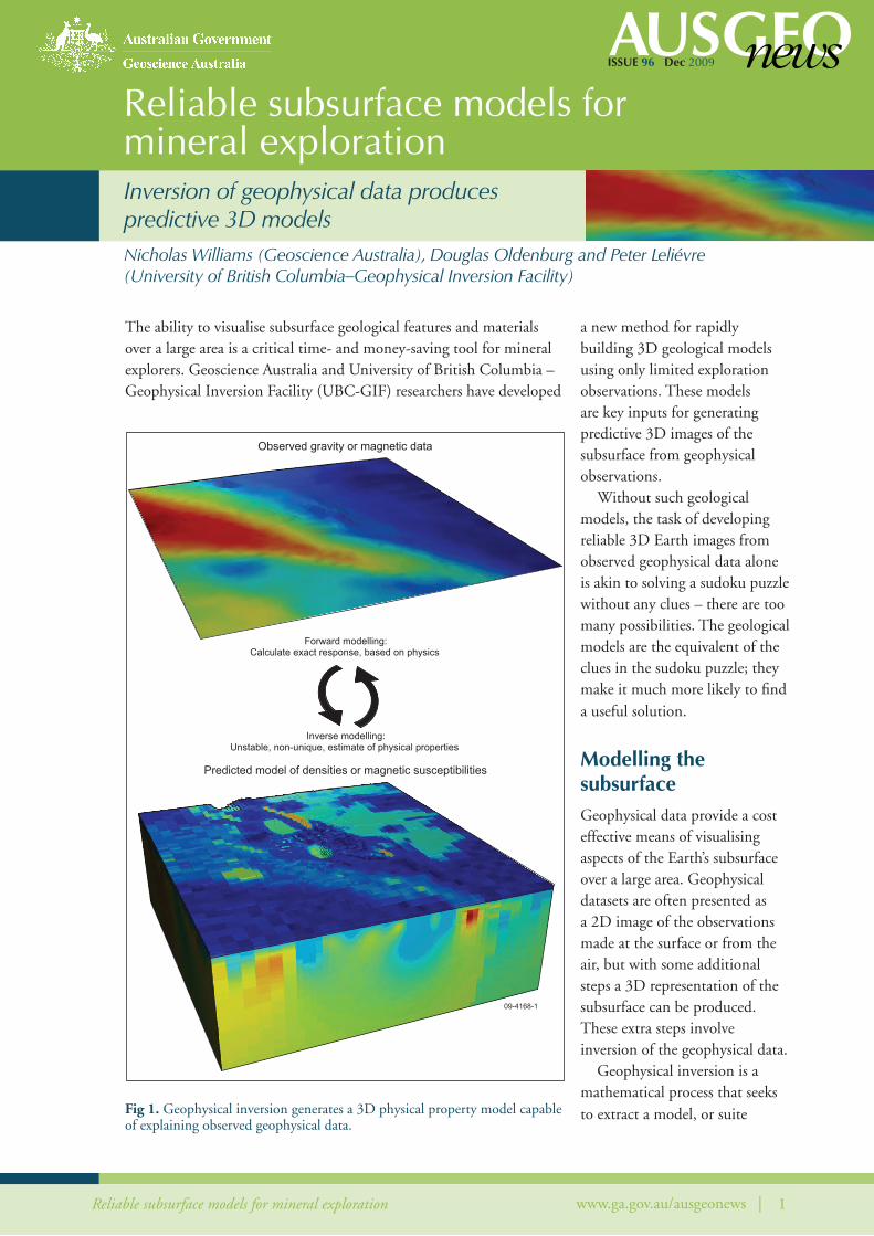
Observed gravity or magnetic data
Forward modelling:Calculate exact response, based on physics
Unstable, non-unique, estimate of physical propertiesInverse modelling:
Predicted model of densities or magnetic susceptibilities
Fig 1. Geophysical inversion generates a 3D physical property model capable of explaining observed geophysical data.
issue 96 Dec 2009
Reliable subsurface models for mineral exploration 2www.ga.gov.au/ausgeonews |
• A reference property which provides the best estimate of the mean physical property (density or magnetic susceptibility) in the cell.
• A smallness weight which provides an estimate of the reliability of the assigned reference property.
• Lower and upper physical property bounds indicating the limits on the property range that can be assigned to the cell. These effectively represent a confidence interval on the supplied reference property.
• Smoothness weights controlling the variation in properties between each adjacent cell in each direction.
The inversion will generate a physical property model with a property for each cell that lies between the defined bounds and is as close as possible to the supplied reference property, while still reproducing the observed geophysical data. If possible, the reference model physical properties will be matched more closely in those cells that have the highest reliability or smallness weights.
Assigning observations to the modelThere are two main classes of observations that can be utilised in building a physical property model from geological data: 1) measurements of physical properties and 2) observations or interpretations of rock types or alteration styles. Physical property measurements are
of models, that represent the subsurface distribution of physical
properties that can explain an observed geophysical dataset (figure 1).
A limitation of inversions is that they provide non-unique results;
many models could be generated that produce the same geophysical
response or image.
The most desirable model is one that explains the observed
geophysical data and also reproduces known geological features.
This can only be achieved by including any available geological
information into the inversions as constraints which restrict the range
of possible results based on geological knowledge. The inversion will
then seek a 3D model that explains the geophysical observations while
also reproducing the expected geology.
One approach to achieving this integration is to specify a full 3D
model of geological observations and interpretations to the inversion
and test the hypothesis that those interpretations are consistent with the
geophysical data (McGaughey 2007; McInerney et al 2007; Oldenburg
and Pratt 2007). However, in greenfields mineral exploration where
geological knowledge is limited, it may be impossible to define a reliable
3D model everywhere in the region of interest.
The ‘sparse data’ approach
An alternate approach is to supply only the available sparse geological
observations to the inversion to generate a prediction about the
subsurface distribution of geological features required to satisfy
both the known geological constraints and the observed geophysical
data. This approach has the added benefit that most geological
interpretation can be postponed until after the inversions have been
performed. This reduces the lead time to recover an inversion result
and enables the results of inversions to be used in decisions to acquire
further geological and geophysical data or to assist with geological
interpretation.
The authors have developed a new model-building method for
preparing the geological constraints required for this ‘sparse data’
approach. It is specifically targeted for use with the UBC-GIF
GRAV3D and MAG3D gravity and magnetic inversion programs
(Li and Oldenburg 1996; Li and Oldenburg 1998). The UBC–GIF
inversion approach allows geological constraints to be assigned to each
cell within a 3D model using four sets of parameters:
“The most desirable model is one that explains the observed geophysical data and also reproduces known geological features.”
issue 96 Dec 2009
Reliable subsurface models for mineral exploration 3www.ga.gov.au/ausgeonews |
most directly related to building a physical property model; however they may not be collected systematically. Observations of geology are far more common and are available in published surface maps for all of Australia. Since most geological units and rock types have characteristic (but not necessarily unique) physical properties, observations of rock types and alteration may be used as a proxy for actual property measurements. A key component of building a physical property model based on rock type observations is therefore to link the geological observations to appropriate physical property information. This is done early in the model building process via the semi-automated creation of a physical property database for the model.
Once the physical property database is created, the model building routine loads the various data files containing those geological observations and extracts the 3D coordinates at which the observations occur. The data that can be used include text files of surface sample property measurements, drill hole and drill core property measurements and geology logs, ArcView shapefile polygon surface and basement geology maps, cross section or reflection seismic interpretations, and full 3D models if available. The physical property database is used to convert geological observations into appropriate physical property estimates.
The reference model depicting the expected geology is populated by calculating the mean of the most reliable property measurements or estimates in each cell. A confidence interval at a specified percentage level of confidence (typically 95 per cent) gives property bounds that limit the likely range of properties. The spatial distribution of observations within a cell is used to assign smallness weights to each cell indicating the reliability of the reference property for that cell, so that poorly-sampled cells have a lower reliability than well-sampled cells.
expanding the model beyond observationsThe constraining physical property model created thus far is based only on the geological data and is only enforced where observations are available. In well-studied areas, a significant number of the cells may be constrained by observations. However, in data-poor environments, such as early exploration stages, few cells will have constraints. Given that there is usually some continuity of geological units along their strike and dip, an option is provided to extrapolate the observed data a short distance into surrounding cells. The method calculates an ellipsoidal buffer zone to represent the zone of influence around each data cell. The shape and orientation of the buffer zone depends upon the observed or inferred structural orientation. The longest buffer axis extends along the strike in the dip plane.
The shortest buffer axis lies perpendicular to the dip plane.
All cells within a buffer zone are assigned the same best property estimate used for the reference model cell at the centre of the buffer. The reliability of constraints in the buffer is reduced with increasing distance from the original geological observations by reducing the smallness weight and expanding the assigned property bounds with distance from the observation. Where several buffers overlap, weighted average property estimates, smallness weights and bounds are calculated that reflect the distance from each observation, as well as the reliability of the original observations.
smoothness weightsSmoothness weights define how smoothly the physical properties in the recovered inversion should vary between adjacent cells. There are three main geological scenarios to which smoothness weights can be usefully applied:
• Allowing sharp changes in properties across geological contacts where they are known.
• Promoting smooth extrapolation of properties away from observation locations into cells that lack observations, as an alternative to using buffers.
• Retaining the natural variability or roughness in physical properties observed in the reference model.
issue 96 Dec 2009
Reliable subsurface models for mineral exploration 4www.ga.gov.au/ausgeonews |
These situations may arise individually, or in combination, and each is handled automatically within the model building program.
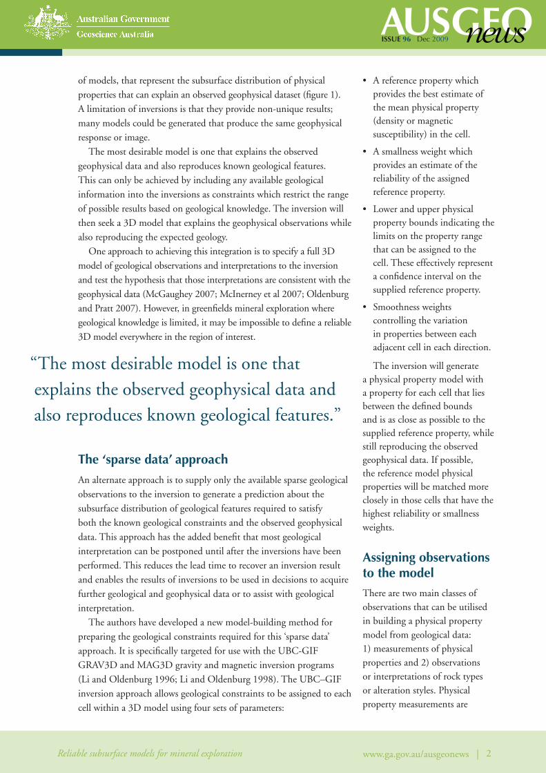
synthetic exampleThe benefit of including a constraining model based on just the available geological observations in an inversion can be demonstrated using a simple synthetic gravity inversion. Figure 2a shows a profile through the gravity response calculated from the 3D synthetic model of known densities which are shown in cross-section view in figure 2b. When the full gravity data set is inverted using default settings in the
UBC-GIF GRAV3D program,
a smooth 3D density model
is recovered that explains the
observed gravity data, as shown
in figure 2c.
Basic surface mapping,
two drill holes, and some
density measurements can be
combined by using the methods
outlined earlier. This generates
a model of expected densities
(figure 2d) as well as bounds
constraints, smallness weights
and smoothness weights. When
this information is included
in the gravity inversion, the
predicted densities give a much
more accurate depiction of the
true subsurface (figure 2e). This
final inversion result can be
more reliably used for further
exploration or targeting. The
non-uniqueness of inversions
is demonstrated by the fact
that all three models shown in
figure 2 (b, c, and e) reproduce
the observed gravity response
equally well.
Application
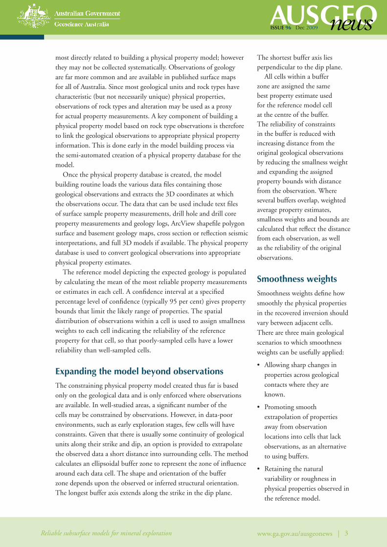
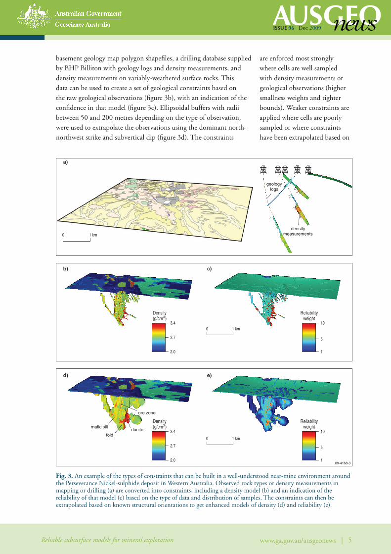
An example of the constraints that can be built using sparse geological data from the Perseverance komatiite-hosted nickel sulphide deposit in Western Australia is shown in figure 3. This example uses all available geological information surrounding the deposit to create density constraints for gravity inversions. The available data (figure 3a) includes Geoscience Australia and Geological Survey of Western Australia surface and
09-4168-2
0
0.5
1.0
8
0
-6
0
0.5
1.0
0
0.5
1.0
0
0.5
1.0
Dep
th (k
m)
Dep
th (k
m)
Dep
th (k
m)
Dep
th (k
m)
a)
b)
c)
d)
e)
3.51.9 2.1 2.3 2.5 2.7 2.9 3.1 3.3
new target
new target
(surface mapping)
(2 drill holes)(no information)
ore bodiesregolith
2 km0
Gra
vity
(mG
al)
Density (g/cm )3
Fig. 2. A simple synthetic example demonstrating the effect of including constraints based on surface mapping and two hypothetical drill holes (d) in a gravity inversion. Although both the geologically-unconstrained (c) and constrained (e) results explain the observed gravity data (a) equally well, the constrained result is a much more reliable predictor of the true geology (b).
issue 96 Dec 2009
Reliable subsurface models for mineral exploration 5www.ga.gov.au/ausgeonews |
basement geology map polygon shapefiles, a drilling database supplied by BHP Billiton with geology logs and density measurements, and density measurements on variably-weathered surface rocks. This data can be used to create a set of geological constraints based on the raw geological observations (figure 3b), with an indication of the confidence in that model (figure 3c). Ellipsoidal buffers with radii between 50 and 200 metres depending on the type of observation, were used to extrapolate the observations using the dominant north-northwest strike and subvertical dip (figure 3d). The constraints
are enforced most strongly where cells are well sampled with density measurements or geological observations (higher smallness weights and tighter bounds). Weaker constraints are applied where cells are poorly sampled or where constraints have been extrapolated based on
3.4
2.0
10
1
2.7 5
b) c)
d)
mafic sill
folddunite
ore zone
3.4
2.0
10
1
2.7 5
0 1 km
0 1 km
densitymeasurements
geologylogs
0 1 km
09-4168-3
a)
Density(g/cm )3
Density(g/cm )3
e)
Reliabilityweight
Reliabilityweight
Fig. 3. An example of the types of constraints that can be built in a well-understood near-mine environment around the Perseverance Nickel-sulphide deposit in Western Australia. Observed rock types or density measurements in mapping or drilling (a) are converted into constraints, including a density model (b) and an indication of the reliability of that model (c) based on the type of data and distribution of samples. The constraints can then be extrapolated based on known structural orientations to get enhanced models of density (d) and reliability (e).
issue 96 Dec 2009
Reliable subsurface models for mineral exploration 6www.ga.gov.au/ausgeonews |
nearby observations (figure 3e).
Strong data-based constraints
are specified in 2.8 per cent
of the model cells and weaker
extrapolated constraints are
defined in an additional 17.2 per
cent of the model.
Even prior to running the
inversions, the constraint
models provide a unique view of
some of the geological features
at Perseverance. The density
reference model in figure 3d
shows several known geological
features including a dense dunite
core, and maps, in 3D, a fold
intersected by only limited
drilling at a depth of 1500
metres. It also shows patches
of the dense massive sulphides
and thin subvertical mafic and
ultramafic units west of the
Perseverance open pit.
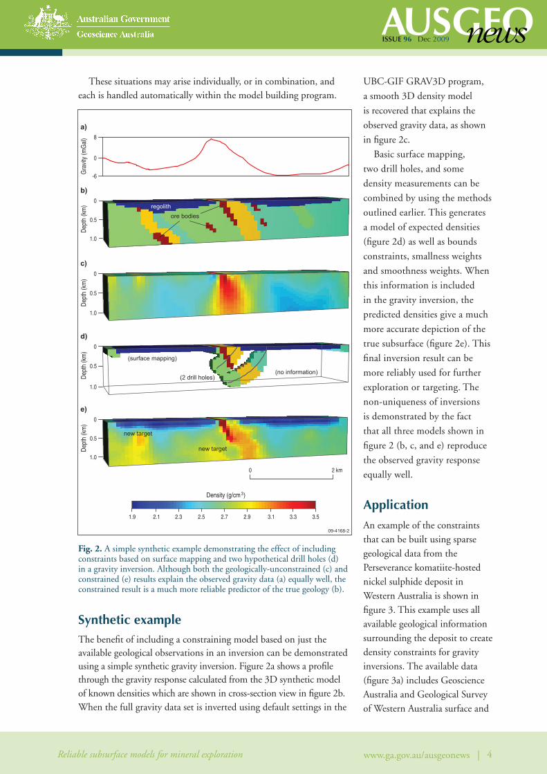
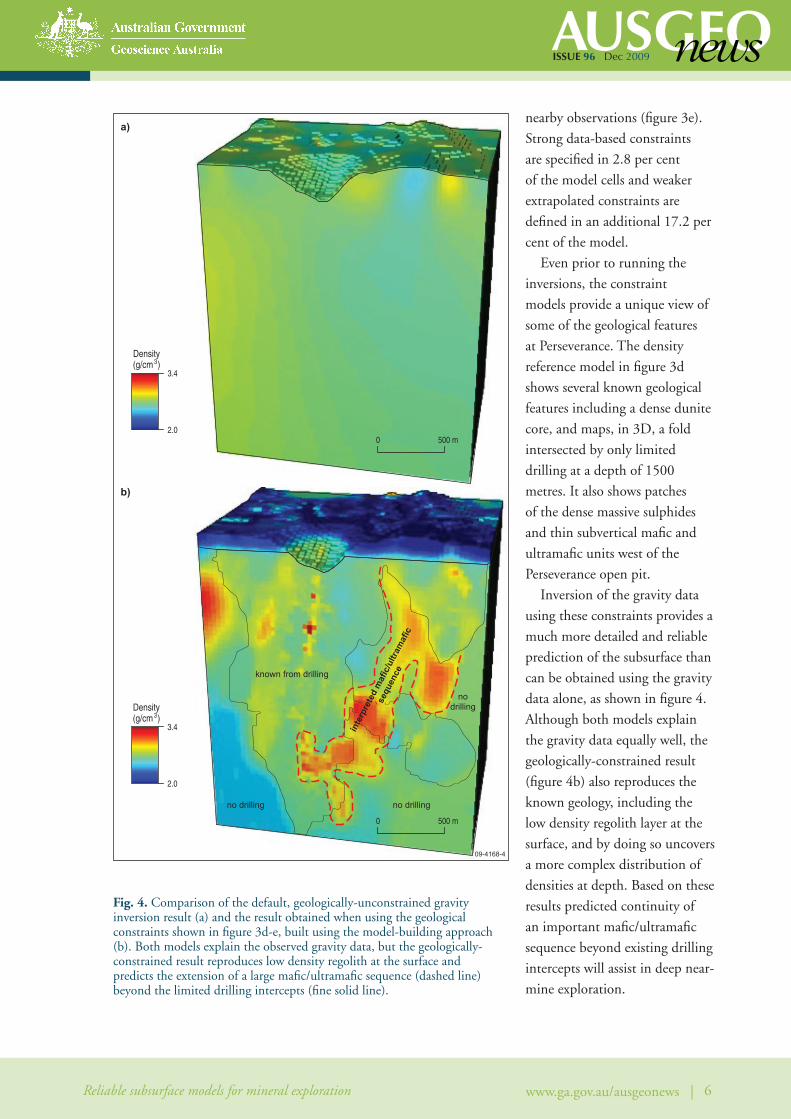
Inversion of the gravity data
using these constraints provides a
much more detailed and reliable
prediction of the subsurface than
can be obtained using the gravity
data alone, as shown in figure 4.
Although both models explain
the gravity data equally well, the
geologically-constrained result
(figure 4b) also reproduces the
known geology, including the
low density regolith layer at the
surface, and by doing so uncovers
a more complex distribution of
densities at depth. Based on these
results predicted continuity of
an important mafic/ultramafic
sequence beyond existing drilling
intercepts will assist in deep near-
mine exploration.
09-4168-4
no drilling no drilling
nodrilling
known from drilling
a)
b)
3.4
2.0
Density(g/cm )3
3.4
2.0
Density(g/cm )3
inte
rpre
ted
maf
ic/u
ltram
afic
sequ
ence
0 500 m
0 500 m
Fig. 4. Comparison of the default, geologically-unconstrained gravity inversion result (a) and the result obtained when using the geological constraints shown in figure 3d-e, built using the model-building approach (b). Both models explain the observed gravity data, but the geologically-constrained result reproduces low density regolith at the surface and predicts the extension of a large mafic/ultramafic sequence (dashed line) beyond the limited drilling intercepts (fine solid line).
issue 96 Dec 2009
Reliable subsurface models for mineral exploration 7www.ga.gov.au/ausgeonews |
summaryThe sparse constraint model builder provides a quick and efficient means of automatically producing data-based constraining models for geophysical inversions. Although specifically developed for use with the UBC–GIF inversion programs, the treatment of the different types of geological information could be applied for use in any inversion or modelling algorithm. The procedure itself is primarily a data management routine to provide a systematic and repeatable way of combining geological observations and physical property measurements into a single, self-consistent model. When used in inversions, the constraints provide a means to effectively combine geological observations with geophysical data, to produce holistic predictive models of the subsurface. Geoscience Australia’s Onshore Energy and Minerals Division has been using these techniques in its North Queensland and Gawler-Curnamona regional programs to recover more reliable 3D subsurface models as part of its ongoing Onshore Energy Security Program.
Physical property data are integral to holistic interpretations since they provide the critical link between geology and the observed geophysical responses. An understanding of the expected physical properties is therefore a crucial component in any geophysical interpretation. The method outlined here demonstrates an efficient way to use physical property measurements to develop constraints for inversions. It is hoped that this provides justification for acquiring more property measurements in the field. Geoscience Australia is currently planning the development of a national rock property database to improve the availability of reliable physical property measurements.
AcknowledgementsThis study was conducted as part of a PhD research program undertaken at the University of British Columbia – Geophysical Research Facility in Vancouver, Canada. It was sponsored by Geoscience Australia, the pmd*CRC, Anglo American, Anglo Gold Ashanti, Barrick Gold, BHP Billiton, Geoinformatics Exploration Canada, Teck, Vale Inco, Xstrata, and the Natural Sciences and Engineering Research Council of Canada. BHP Billiton is thanked for permission to publish the Perseverance deposit example.
For more informationphone Nick Williams on +61 2 6249 5807 email [email protected]
ReferencesLi Y and Oldenburg DW. 1996. 3-D inversion of magnetic data. Geophysics. 61(2): 394–408.
Li Y and Oldenburg DW. 1998. 3-D inversion of gravity data. Geophysics. 63(1): 109–119.
McGaughey J. 2007. Geological models, rock properties, and the 3D inversion of geophysical data. In: B. Milkereit (ed), Proceedings of Exploration 07: Fifth Decennial International Conference on Mineral Exploration, 473–483.
McInerney P et al. 2007. Improved 3D geology modelling using an implicit function interpolator and forward modelling of potential field data. In: B. Milkereit (ed), Proceedings of Exploration 07: Fifth Decennial International Conference on Mineral Exploration, 919–922.
Oldenburg DW & Pratt DA. 2007. Geophysical inversion for mineral exploration: A decade of progress in theory and practice. In: B. Milkereit (ed), Proceedings of Exploration 07: Fifth Decennial International Conference on Mineral Exploration, 61–95.
Related websites/articlesGeoscience Australia’s Onshore Energy Geodynamic Framework Projectwww.ga.gov.au/minerals/research/national/oegf/index.jsp
The Geophysical Inversion Facility at The University of British Columbiawww.eos.ubc.ca/ubcgif/
Geologically-constrained UBC–GIF gravity and magnetic inversions with examples from the Agnew-Wiluna greenstone belt, Western Australia, PhD Thesis by Nicholas Williamshdl.handle.net/2429/2744