relion motor protection and control rem615 ansi ... · motor protection and control rem615 ansi...
TRANSCRIPT

Relion® 615 Series
Motor Protection and ControlREM615 ANSIApplication Manual


Document ID: 1MAC259901-MBIssued:3/1/2011
Revision: BProduct version: 4.0
© Copyright 2011 ABB. All rights reserved.

Copyright
This document and parts thereof must not be reproduced or copied without written permission from ABB, and the contents thereof must not be imparted to a third party, nor used for any unauthorized purpose.
The software or hardware described in this document is furnished under a license and may be used, copied, or disclosed only in accordance with the terms of such license.
Trademarks
ABB and Relion are registered trademarks of ABB Group. All other brand or product names mentioned in this document may be trademarks or registered trademarks of their respective holders.
Warranty
Please inquire about the terms of warranty from your nearest ABB representative.
ABB Inc.Distribution Automation4300 Coral Ridge DriveCoral Springs, FL 33065, USAToll-free: 1 (800) 523-2620Phone: +1 954-752-6700Fax: +1 954 345-5329http://www.abb.com/substationautomation

Disclaimer
The data, examples and diagrams in this manual are included solely for the concept or product description and are not to be deemed as a statement of guaranteed properties. All persons responsible for applying the equipment addressed in this manual must satisfy themselves that each intended application is suitable and acceptable, including that any applicable safety or other operational requirements are complied with. In particular, any risks in applications where a system failure and/or product failure would create a risk for harm to property or persons (including but not limited to personal injuries or death) shall be the sole responsibility of the person or entity applying the equipment, and those so responsible are hereby requested to ensure that all measures are taken to exclude or mitigate such risks.
This document has been carefully checked by ABB but deviations cannot be completely ruled out. In case any errors are detected, the reader is kindly requested to notify the manufacturer. Other than under explicit contractual commitments, in no event shall ABB be responsible or liable for any loss or damage resulting from the use of this manual or the application of the equipment.

Conformity
This product complies with the directive of the Council of the European Communities on the approximation of the laws of the Member States relating to electromagnetic compatibility (EMC Directive 2004/108/EC) and concerning electrical equipment for use within specified voltage limits (Low-voltage directive 2006/95/EC). This conformity is the result of tests conducted by ABB in accordance with the product standards EN 50263 and EN 60255-26 for the EMC directive, and with the product standards EN 60255-6 and EN 60255-27 for the low voltage directive. The IED is designed in accordance with the international standards of the IEC 60255 series and ANSI C37.90. This IED complies with the UL 508 certification.

1MAC259901-MB B Section
REM615 ANSI 1Application Manual
Section 1 Introduction ...........................................................................3This manual ..............................................................................................3Intended audience ....................................................................................3Product documentation.............................................................................4
Product documentation set..................................................................4Document revision history ...................................................................5Related documentation........................................................................5
Symbols and conventions.........................................................................5Safety indication symbols ....................................................................5Manual conventions.............................................................................6Functions, codes and symbols ............................................................7
Section 2 REM615 overview.................................................................9Overview...................................................................................................9
Product version history ........................................................................9PCM600 and IED connectivity package version..................................9
Operation functionality ............................................................................10Optional features ...............................................................................10
Physical hardware ..................................................................................10Local HMI................................................................................................13
LCD ...................................................................................................13LEDs..................................................................................................14Keypad ..............................................................................................14
Web HMI.................................................................................................15Authorization...........................................................................................16Communication.......................................................................................17
Section 3 REM615 configurations.......................................................19REM615 variant list.................................................................................19Presentation of standard configurations .................................................19
Standard configurations.....................................................................20Standard Configuration for order code functional application A ............23
Applications .......................................................................................23 Functions ..........................................................................................24Default Input/Output (I/O) assignments ............................................26Typical connection diagram...............................................................28Functional diagrams ..........................................................................29Functional diagrams for protection ....................................................29Functional diagrams for control functions .........................................34Functional diagrams for condition monitoring ...................................36Functional diagrams for Measurements ............................................38Functional diagrams for other functions ...........................................39Functional diagrams for logging functions ........................................39

Section 1MAC259901-MB B
2 REM615 ANSIApplication Manual
Functional diagrams for I/O and Alarm LEDs ...................................40Standard Configuration for order code functional application B .............43
Applications .......................................................................................43 Functions ..........................................................................................44 Default Input/Output (I/O) assignments ...........................................46 Typical connection diagrams ............................................................48Functional diagrams ..........................................................................49Functional diagrams for protection ....................................................49Functional diagrams for control functions .........................................56Functional diagrams for condition monitoring ...................................57Functional diagrams for Measurements ............................................59Functional diagrams for other functions ............................................59Functional diagrams for logging functions ........................................60Functional diagrams for I/O and Alarm LEDs ...................................60
Standard configuration for order code functional application C and D....63Applications .......................................................................................63Functions ...........................................................................................64Default Input/Output (I/O) assignments .............................................66 Typical connection diagrams ............................................................69Functional diagrams ..........................................................................71Functional diagrams for protection ....................................................71Functional diagrams for control functions .........................................79Functional diagrams for condition monitoring ...................................81Functional diagrams for Measurements ............................................83Functional diagrams for other functions ............................................83Functional diagrams for logging functions ........................................84Functional diagrams for I/O and Alarm LEDs ...................................84
Standard Configuration for order code functional application E and F ...87Applications .......................................................................................87Functions ...........................................................................................88 Default Input/Output (I/O) assignments ............................................90Typical connection diagrams .............................................................93Functional diagrams ..........................................................................94Functional diagrams for protection ....................................................94Functional diagrams for control functions .......................................102Functional diagrams for condition monitoring .................................103Functional diagrams for Measurements ..........................................105Functional diagrams for other functions ..........................................106Functional diagrams for logging functions ......................................106Functional diagrams for I/O and Alarm LEDs .................................107

1MAC259901-MB B Section 1Introduction
REM615 ANSI 3Application Manual
Section 1 Introduction
1.1 This manual
The application manual contains application descriptions and setting guidelines sorted per function. The manual can be used to find out when and for what purpose a typical protection function can be used. The manual can also be used when calculating settings.
1.2 Intended audience
This manual addresses the protection and control engineer responsible for planning, pre-engineering and engineering.
The protection and control engineer must be experienced in electrical power engineering and have knowledge of related technology, such as communication and protocols.

Section 1 1MAC259901-MB B
Introduction
4 REM615 ANSIApplication Manual
1.3 Product documentation
1.3.1 Product documentation set
Figure 1: The intended use of manuals in different life cyclesThe engineering manual contains instructions on how to engineer the IEDs using the different tools in PCM600. The manual provides instructions on how to set up a PCM600 project and insert IEDs to the project structure. The manual also recommends a sequence for engineering of protection and control functions, LHMI functions as well as communication engineering for IEC 61850 and DNP3.
The installation manual contains instructions on how to install the IED. The manual provides procedures for mechanical and electrical installation. The chapters are organized in chronological order in which the IED should be installed.
The commissioning manual contains instructions on how to commission the IED. Themanual can also be used by system engineers and maintenance personnel for assistance during the testing phase. The manual provides procedures for checking of external circuitry and energizing the IED, parameter setting and configuration as well as verifying settings by secondary injection. The manual describes the process of testing an IED in a substation which is not in service. The chapters are organized in chronological order in which the IED should be commissioned.
The operation manual contains instructions on how to operate the IED once it has been commissioned. The manual provides instructions for monitoring, controlling and setting
Pla
nn
ing
& p
urc
has
e
En
gin
eeri
ng
Inst
allin
g
Co
mm
issi
on
ing
Op
erat
ion
Mai
nte
nan
ce
Dec
om
mis
sio
nin
gD
ein
stal
lin
g &
Dis
po
sal
Application manual
Operation manual
Installation manual
Engineering manual
Communication Protocol manual
Technical manual
Protocol Points List manual

1MAC259901-MB B Section 1Introduction
REM615 ANSI 5Application Manual
the IED. The manual also describes how to identify disturbances and how to view calculated and measured power grid data to determine the cause of a fault.
The application manual contains application descriptions and setting guidelines sorted per function. The manual can be used to find out when and for what purpose a typical protection function can be used. The manual can also be used when calculating settings.
The technical manual contains application and functionality descriptions and lists function blocks, logic diagrams, input and output signals, setting parameters and technical data sorted per function. The manual can be used as a technical reference during the engineering phase, installation and commissioning phase, and during normal service.
The communication protocol manual describes a communication protocol supported by the IED. The manual concentrates on vendor-specific implementations.
The point list manual describes the outlook and properties of the data points specific to the IED. The manual should be used in conjunction with the corresponding communication protocol manual.
1.3.2 Document revision history
1.3.3 Related documentation
1.4 Symbols and conventions
1.4.1 Safety indication symbols
Document revision/date Product version HistoryA/01/20/2010 2.0 First release
B/03/01/2011 4.0 Content updated to correspond to the product version
Download the latest documents from the ABB web site http://www.abb.com/substation automation.
Name of the document Document IDModbus Communication Protocol Manual 1MAC052634-MB
DNP3 Communication Protocol Manual 1MAC052460-MB
IEC 61850 Engineering Guide 1MAC106231-MB
Installation Manual 1MAC051065-MB
Operation Manual 1MAC050592-MB
Technical Manual 1MAC050144-MB
The electrical warning icon indicates the presence of a hazard which could result in electrical shock.

Section 1 1MAC259901-MB B
Introduction
6 REM615 ANSIApplication Manual
Although warning hazards are related to personal injury, it should be understood that operation of damaged equipment could, under certain operational conditions, result in degraded process performance leading to personal injury or death. Therefore, comply fully with all warning and caution notices.
1.4.2 Manual conventionsConventions used in IED manuals. A particular convention may not be used in this manual.
• Abbreviations and acronyms in this manual are spelled out in the glossary. The glossary also contains definitions of important terms.
• Push button navigation in the LHMI menu structure is presented by using the push button icons, for example:
To navigate between the options, use and .
• HMI menu paths are presented in bold, for example:
Select Main menu > Settings.
• LHMI messages are shown in Courier font, for example:
To save the changes in non-volatile memory, select Yes and press .
• Parameter names are shown in italics, for example:
The function can be enabled and disabled with the Operation setting.
• Parameter values are indicated with quotation marks, for example:
The corresponding parameter values are "Enabled" and "Disabled".
• IED input/output messages and monitored data names are shown in Courier font, for example:
When the function picks up, the PICKUP output is set to TRUE.
• Dimensions are provided both in inches and mm. If it is not specifically mentioned then the dimension is in mm.
The warning icon indicates the presence of a hazard which could result in personal injury.
The caution icon indicates important information or warning related to the concept discussed in the text. It might indicate the presence of a hazard which could result in corruption of software or damage to equipment or property.
The information icon alerts the reader to important facts and conditions.
The tip icon indicates advice on, for example, how to design your project or how to use a certain function.

1MAC259901-MB B Section 1Introduction
REM615 ANSI 7Application Manual
1.4.3 Functions, codes and symbolsAll available functions are listed in the table. All of them may not be applicable to all products.
Table 1: Functions included in standard configurations
Standard configuration functionality IEC 61850 ANSI/C37.2 IEC60617Protection
Three-phase non-directional overcurrent protection, low stage, instance 1
PHLPTOC1 51P 3I> (1)
Three-phase non-directional overcurrent protection, high stage, instance 1
PHHPTOC1 50P 3I>> (1)
Non-directional ground-fault protection, low stage, instance 1
EFLPTOC1 51G Io> (1)
Non-directional ground-fault protection, high stage, instance 1
EFHPTOC1 50G Io>> (1)
Directional ground-fault protection, low stage, instance 1
DEFLPDEF1 67/51N Io> -> (1)
Residual overvoltage protection, instance 1 ROVPTOV1 59G Uo> (1)
Residual overvoltage protection, instance 2 ROVPTOV2 59N Uo> (2)
Three-phase under-voltage protection, instance 1 PHPTUV1 27 3U< (1)
Three-phase overvoltage protection, instance 1 PHPTOV1 59 3U> (1)
Positive-sequence undervoltage protection, instance 1
PSPTUV1 27PS U1<(1)
Negative-sequence overvoltage protection, instance 1
NSPTOV1 47 U2>(1)
Frequency protection, instance 1 FRPFRQ1 81 f>/f<,df/dt(1)
Negative-sequence overcurrent protection for motors, instance 1
MNSPTOC1 46M-1 I2>M(1)
Negative-sequence overcurrent protection for motors, instance 2
MNSPTOC2 46M-2 I2>M(2)
Loss of load supervision, instance 1 LOFLPTUC1 37M-1 3I<(1)
Loss of load supervision, instance 2 LOFLPTUC2 37M-2 3I<(2)
Motor load jam protection JAMPTOC1 51LR 1st>
Motor start-up supervision STTPMSU1 66/51LRS Is2t n<
Phase reversal protection PREVPTOC1 46R I2>>
Thermal overload protection for motors MPTTR1 49M 3Ith>M
Motor differential protection MPDIF1 87M 3dl>M
Circuit breaker failure protection, instance 1 CCBRBRF1 50BF 3I>/Io>BF(1)
Master trip, instance 1 TRPPTRC1 86/94-1 Master Trip(1)
Master trip, instance 2 TRPPTRC2 86/94-2 Master Trip (2)
Arc protection, instance 1 ARCSARC1 AFD-1 ARC (1)
Arc protection, instance 2 ARCSARC2 AFD-2 ARC (2)
Arc protection, instance 3 ARCSARC3 AFD-3 ARC (3)
Control
Circuit-breaker control, instance 1 CBCBR1 52 I <-> O CB (1)

Section 1 1MAC259901-MB B
Introduction
8 REM615 ANSIApplication Manual
Emergency startup ESMGAPC1 62EST ESTART
Condition Monitoring
Circuit-breaker condition monitoring, instance 1 SSCBR1 52CM CBCM(1)
Trip circuit supervision, instance 1 TCSSCBR1 TCM-1 TCS(1)
Trip circuit supervision, instance 2 TCSSCBR2 TCM-2 TCS(2)
Current circuit supervision CCRDIF1 CCM MCS 3I
Fuse Failure supervision, instance 1 SEQRFUF1 60 FUSEF(1)
Runtime counter for machines and devices, instance 1
MDSOPT1 OPTM-1 OPTS(1)
Runtime counter for machines and devices, instance 2
MDSOPT2 OPTM-2 OPTS(2)
Measurement
Three-phase current measurement, instance 1 CMMU1 IA, IB, IC 3I
Three-phase current measurement, instance 2 CMMU2 IA, IB, IC (2) 3I(B)
Sequence current measurement, instance 1 CSMSQI1 I1, I2, I0 I1, I2, I0
Sequence current measurement, instance 2 CSMSQI2 I1, I2, I0 (2) I1, I2, I0(B)
Residual current measurement, instance 1 RESCMMU1 IG Io
Three-phase voltage measurement, instance 1 VMMU1 VA, VB, VC 3U
Residual voltage measurement RESVMMU1 VG Uo
Sequence voltage measurement, instance 1 VSMSQI1 V1, V2, V0 U1, U2, U0
Single-phase power and energy measurement, instance 1
SPEMMU1 SP, SE SP, SE
Three-phase power and energy measurement, instance 1
PEMMU1 P, E P, E
Recorder
Disturbance recorder RDRE1 DFR -
Fault recorder FLTMSTA1 FR -
Sequence event recorder SER SER -
Other Functions
Minimum pulse timer (2 pcs), instance 1 TPGAPC1 TP-1 TP (1)
Minimum pulse timer (2 pcs), instance 2 TPGAPC2 TP-2 TP (2)
Minimum pulse timer (2 pcs), instance 3 TPGAPC3 TP-3 TP (3)
Minimum pulse timer (2 pcs), instance 4 TPGAPC4 TP-4 TP (4)
Pulse timer (8 pcs), instance 1 PTGAPC1 PT-1 PT (1)
Pulse timer (8 pcs), instance 2 PTGAPC2 PT-2 PT (2)
Time delay off (8 pcs), instance 1 TOFGAPC1 TOF-1 TOF (1)
Time delay off (8 pcs), instance 2 TOFGAPC2 TOF-2 TOF (2)
Time delay on (8 pcs), instance 1 TONGAPC1 TON -1 TON (1)
Time delay on (8 pcs), instance 2 TONGAPC2 TON -2 TON (2)
Set reset (8 pcs), instance 1 SRGAPC1 SR-1 SR (1)
Set reset (8 pcs), instance 2 SRGAPC2 SR-2 SR (2)
Move (8 pcs), instance 1 MVGAPC1 MV-1 MV (1)
Move (8 pcs), instance 2 MVGAPC2 MV-2 MV (2)
Standard configuration functionality IEC 61850 ANSI/C37.2 IEC60617

1MAC259901-MB B Section 2REM615 overview
REM615 ANSI 9Application Manual
Section 2 REM615 overview
2.1 Overview
REM615 is a dedicated motor IED (Intelligent Electronic Device) designed for the protection, control, measurement and supervision of utility substations and industrial power systems. REM615 is a member of ABB’s Relion® product family and part of its 615 protection and control product series. The 615 series IEDs are characterized by their compactness and withdrawable design.
Re-engineered from the ground up, the 615 series has been designed to unleash the full potential of the IEC 61850 standard for communication and interoperability between substation automation devices.
The IED provides main protection for motors in distribution networks. The IED is also used as back-up protection in applications, where an independent and redundant protection system is required.
Depending on the chosen standard configuration, the IED is adapted for the protection of overhead line and cable feeders in isolated neutral, resistance grounded, compensated and solidly grounded networks. Once the standard configuration IED has been given the application-specific settings, it can directly be put into service.
The 615 series IEDs support a range of communication protocols including IEC 61850 with GOOSE messaging, IEC 60870-5-103, Modbus® and DNP3.
2.1.1 Product version history
2.1.2 PCM600 and IED connectivity package version• Protection and Control IED Manager PCM600 Ver. 2.3 (plus PCM600 Rollup
20110126 2.3) or later
• IED Connectivity Package REM615 ANSI Ver. 4.0 ANSI
• Parameter Setting • Application configuration• Firmware Update • Disturbance Handling
Product version Product history2.0 • Product released
4.0 • User programming through Application Configuration tool• Frequency measurement protection • Single phase power and energy measurement• Load profile recorder

Section 2 1MAC259901-MB B
REM615 overview
10 REM615 ANSIApplication Manual
• Signal Monitoring • Life Cycle Traceability • Signal Matrix • Communication Management • Configuration Wizard• Label Printing• IED User Management• IED Users
2.2 Operation functionality
2.2.1 Optional features• High speed BIO cards
• The regular binary cards (8BI+4BO) can be replaced with optional binary cards with high speed output (8BI+3HSO). These cards will be replaced at the X110 slot.
• RTD measurement inputs
• A two channel/si channel RTD measurement inputs can be connected to X130 slot.
• Additional BIOs, 6BI+3BO
• Additional binary cards can be used if needed at the X130 slot. (See table 2)
2.3 Physical hardware
The IED consists of two main parts: plug-in unit and case. The plug-in unit content depends on the ordered functionality.
Download connectivity packages from the ABB web site http://www.abb.com/substation automation

1MAC259901-MB B Section 2REM615 overview
REM615 ANSI 11Application Manual
Table 2: Plug-in unit and case
The rated input levels are selected in the IED software for phase current and ground current. The binary input thresholds 18...176 V DC are selected by adjusting the IED's parameter settings.
The connection diagrams of different hardware modules are presented in this manual.
Main unit Slot ID Module ID Content optionsPlug-in unit - DIS HMI 128/128 LCD large display with text and graphics
X100 PSM Auxiliary power/BO module
48-250 V DC/80-240V AC; or 24-60V DC2 normally-open PO contacts2 normally-closed SO contacts2 double-pole PO contacts with TCS1 dedicated internal fault output contact
X110 BIO BI/O module Optional with configuration A, Part of standard configuration B, C, D, E, F8 Binary Inputs4 Binary Outputs
Can be replaced with optional high-speed BIO card for all configurations.8 Binary Inputs3 High speed SO contacts
X120 AIM AI/BI module With Configuration A, C and D,4 Binary Inputs4 Current Inputs with Io
With Configuration B,7 Current Inputs with Io
With Configuration E and F,3 Voltage Inputs4 Current Inputs with Io
Case SIMxxx/BIOxxx/RTDxxx
AIM AI/BI/RTD module
With Configuration C, 4 Binary Outputs5 Voltage Inputs
With Configuration D,1 low current (0.1mA – 20mA) input2 RTD inputs5 Voltage inputs
With Configuration B and F,6 RTD inputs2 low current (0.1mA -20mA) input
Optional BIO(6BI + 3BO) card can be used for other configurations
000 COM Communication module
See technical manual for details about different type of communication modules.
The optional BIO module can be added in the IED to all standard configurations.
See the installation manual for more information about the case and the plug-in unit.

Section 2 1MAC259901-MB B
REM615 overview
12 REM615 ANSIApplication Manual
Table 3: Number of physical connections in standard configurations
Functional application configuration.
Analog channels Binary channels
CT VT RTD mA BI BOA 4 0 0 0 Min – 4
Ma - 18Min – 6Ma - 13
B 7 0 6 2 8 10
C/D 4 5 0/2 0/1 16/12 10
E/F 4 3 0/6 0/2 14/8 13/10

1MAC259901-MB B Section 2REM615 overview
REM615 ANSI 13Application Manual
2.4 Local HMI
Figure 2: LHMIThe LHMI of the IED contains the following elements:
• Display
• Buttons
• LED indicators
• Communication port
The LHMI is used for setting, monitoring and controlling.
2.4.1 LCDThe LHMI includes a graphical LCD that supports two character sizes. The character size depends on the selected language.

Section 2 1MAC259901-MB B
REM615 overview
14 REM615 ANSIApplication Manual
Table 4: Characters and rows on the view
The display view is divided into four basic areas.
Figure 3: Display layout1 Header
2 Icon
3 Content
4 Scroll bar (displayed when needed)
2.4.2 LEDsThe LHMI includes three protection indicators above the display: Normal, Pickup and Trip.
There are also 11 matrix programmable alarm LEDs on front of the LHMI. The LEDs can be configured with PCM600 and the operation mode can be selected with the LHMI, WHMI or PCM600.
There are two additional LEDs which are embedded into the control buttons and . They represent the status of the circuit breaker.
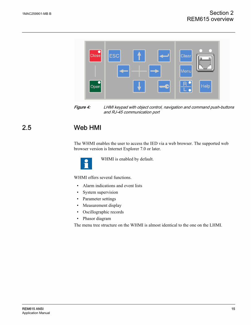
2.4.3 KeypadThe LHMI keypad contains push-buttons which are used to navigate in different views or menus. With the push-buttons you can give open or close commands to one primary object, for example, a circuit breaker, disconnector or switch. The push-buttons are also used to acknowledge alarms, reset indications, provide help and switch between local and remote control mode.
Character size Rows in view Characters on rowLarge, variable width (1314 pixels)
10 rows min 8
1 2
3 4
1MAC259901-MB B Section 2REM615 overview
REM615 ANSI 15Application Manual
Figure 4: LHMI keypad with object control, navigation and command push-buttons and RJ-45 communication port
2.5 Web HMI
The WHMI enables the user to access the IED via a web browser. The supported web browser version is Internet Explorer 7.0 or later.
WHMI offers several functions.
• Alarm indications and event lists
• System supervision
• Parameter settings
• Measurement display
• Oscillographic records
• Phasor diagram
The menu tree structure on the WHMI is almost identical to the one on the LHMI.
WHMI is enabled by default.

Section 2 1MAC259901-MB B
REM615 overview
16 REM615 ANSIApplication Manual
Figure 5: Example view of the WHMIThe WHMI can be accessed locally and remotely.
• Locally by connecting your laptop to the IED via the front communication port.
• Remotely over LAN/WAN.
2.6 Authorization
The user categories have been predefined for the LHMI and the WHMI, each with different rights and default passwords.
The default passwords can be changed with Administrator user rights.
User authorization is disabled by default but WHMI always uses authorization.
1MAC259901-MB B Section 2REM615 overview
REM615 ANSI 17Application Manual
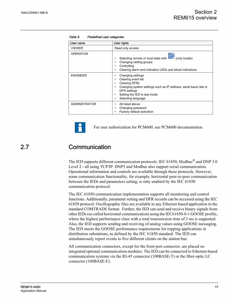
Table 5: Predefined user categories
2.7 Communication
The IED supports different communication protocols: IEC 61850, Modbus® and DNP 3.0 Level 2 - all using TCP/IP. DNP3 and Modbus also support serial communication. Operational information and controls are available through these protocols. However, some communication functionality, for example, horizontal peer-to-peer communication between the IEDs and parameters setting, is only enabled by the IEC 61850 communication protocol.
The IEC 61850 communication implementation supports all monitoring and control functions. Additionally, parameter setting and DFR records can be accessed using the IEC 61850 protocol. Oscillographic files are available to any Ethernet-based application in the standard COMTRADE format. Further, the IED can send and receive binary signals from other IEDs (so called horizontal communication) using the IEC61850-8-1 GOOSE profile, where the highest performance class with a total transmission time of 3 ms is supported. Also, the IED supports sending and receiving of analog values using GOOSE messaging. The IED meets the GOOSE performance requirements for tripping applications in distribution substations, as defined by the IEC 61850 standard. The IED can simultaneously report events to five different clients on the station bus.
All communication connectors, except for the front port connector, are placed on integrated optional communication modules. The IED can be connected to Ethernet-based communication systems via the RJ-45 connector (100BASE-T) or the fiber-optic LC connector (100BASE-F).
User name User rightsVIEWER Read only access
OPERATOR• Selecting remote or local state with (only locally) • Changing setting groups• Controlling• Clearing alarm and indication LEDs and tetual indications
ENGINEER • Changing settings• Clearing event list• Clearing DFRs• Changing system settings such as IP address, serial baud rate or
DFR settings• Setting the IED to test mode • Selecting language
ADMINISTRATOR • All listed above • Changing password• Factory default activation
For user authorization for PCM600, see PCM600 documentation.

Section 2 1MAC259901-MB B
REM615 overview
18 REM615 ANSIApplication Manual

1MAC259901-MB B Section 3REM615 configurations
REM615 ANSI 19Application Manual
Section 3 REM615 configurations
3.1 REM615 variant list
REM615 is intended for protection and control mainly in MV motor applications. The product has four standard configurations covering a wide range of primary circuit configurations in distribution networks based on different system grounding methods.
Some of the functions included in the IED's standard configurations are optional at the time of placing the order. The description of standard configurations covers the full functionality including options, presenting the functionality, flexibility and eternal connections of REM615 with a specific configuration as delivered from the factory.
3.2 Presentation of standard configurations
Functional diagrams
The functional diagrams describe the IED's functionality from the protection, measuring, condition monitoring, recording, control and interlocking perspective. Diagrams show the default functionality with simple symbol logics forming principle diagrams. The eternal connections to primary devices are also shown, stating the default connections to measuring transformers. The positive measuring direction is towards the outgoing feeder, away from the bus bar.
The functional diagrams are divided into sections with each section constituting one functional entity. The eternal connections are also divided into sections. Only the relevant connections for a particular functional entity are presented in each section.
Protection function blocks are part of the functional diagram. They are identified based on their ANSI function number/acronym, but the IEC based symbol and the IEC 61850 names are also included. Some function blocks are used several times in the configuration. To separate the blocks from each other, the IEC 61850 name and ANSI function number are appended with a running number, that is an instance number, from one upwards. The IED’s internal functionality and the eternal connections are separated with a dashed line presenting the IED’s physical casing.
Signal Matri
With Signal Matrix in PCM600 the user can modify the standard configuration according to the actual needs. The IED is delivered from the factory with default connections described in the functional diagrams for BI's, BO's, function to function connections and alarm LEDs. Signal Matrix has a number of different page views, designated as follows:

Section 3 1MAC259901-MB B
REM615 configurations
20 REM615 ANSIApplication Manual
• Binary input
• Binary output
• Analog input
• Functions
There are four IED variant-specific setting groups. Parameters can be set independently for each setting group.
The active setting group (1...6) can be changed with a parameter. The active setting group can also be changed via a binary input if the binary input is enabled for this. To enable the change of the active setting group via a binary input, connect a free binary input with PCM600 to the BI_SG_x input of the Protection block.
Table 6: Binary input states and corresponding active setting groups
The active setting group defined by a parameter is overridden when a binary input is enabled for changing the active setting group.
3.2.1 Standard configurationsThe motor protection IED REM615 is available with si different functional application configurations. Table 7 shows the different configurations available for the IED.
Table 7: Standard configurations
BI state Active setting groupOFF 1
ON 2
Description Functional application configuration
Over-current and load loss protection for small motors. AA
Differential, over-current, load loss and RTD protection for medium to large motors.
BA
Over-current, load loss, phase and ground voltage, frequency protection and power system metering for medium motors.
CA
Over-current, load loss, phase and ground voltage, frequency, RTD protection and power system metering for medium motors.
DA
Over-current, load loss, phase and neutral voltage, frequency protection and power system metering for medium motors.
EA
Over-current, load loss, phase and neutral voltage, frequency, RTD protection and power system metering for medium to large motors.
FA

1MAC259901-MB B Section 3REM615 configurations
REM615 ANSI 21Application Manual
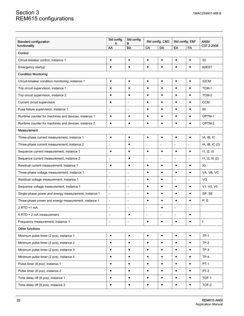
Table 8: Supported functions
Standard configuration functionality
Std config. A
Std config. B Std config. C&D Std config. E&F ANSI/
C37.2-2008AA BA CA DA EA FAProtection
Three-phase non-directional overcurrent protection, low stage, instance 1
● ● ● ● ● ● 51P
Three-phase non-directional overcurrent protection, high stage, instance 1
● ● ● ● ● ● 50P
Non-directional ground-fault protection, low stage, instance 1 ● ● ● ● ● ● 51G
Non-directional ground-fault protection, high stage, instance 1
● ● ● ● ● ● 50G
Directional ground-fault protection, low stage, instance 1 - - ● 1,2) ● 1,2) ● 1,2) ● 1,2) 67/51N
Residual overvoltage protection, instance 1 - - ● ● - - 59G
Residual overvoltage protection, instance 2 - - - - ● ● 59N
Three-phase undervoltage protection, instance 1 - - ● ● ● ● 27
Three-phase overvoltage protection, instance 1 - - ● ● ● ● 59
Positive-sequence undervoltage protection, instance 1 - - ● ● ● ● 27PS
Negative-sequence overvoltage protection, instance 1 - - ● ● ● ● 47
Frequency protection, instance 1 - - ● ● ● ● 81
Negative-sequence overcurrent protection for motors, instance 1
● ● ● ● ● ● 46M-1
Negative-sequence overcurrent protection for motors, instance 2
● ● ● ● ● ● 46M-2
Loss of load supervision, instance 1 ● ● ● ● ● ● 37M-1
Loss of load supervision, instance 2 ● ● ● ● ● ● 37M-2
Motor load jam protection ● ● ● ● ● ● 51LR
Motor start-up supervision ● ● ● ● ● ● 66/51LRS
Phase reversal protection ● ● ● ● ● ● 46R
Thermal overload protection for motors ● ● ● ● ● ● 49M
Motor differential protection - ● - - - - 87M
Circuit breaker failure protection, instance 1 ● ● ● ● ● ● 50BF
Master trip, instance 1 ● ● ● ● ● ● 86/94-1
Master trip, instance 2 ● ● ● ● ● ● 86/94-2
Arc protection, instance 1 ● ● ● ● ● ● AFD-1
Arc protection, instance 2 ● ● ● ● ● ● AFD-2
Arc protection, instance 3 ● ● ● ● ● ● AFD-3
Multi-purpose protection, instance 1 2) - ● - ● - ● MAP-1
Multi-purpose protection, instance 2 2) - ● - ● - ● MAP-2
Multi-purpose protection, instance 3 2) - ● - ● - ● MAP-3
Section 3 1MAC259901-MB B
REM615 configurations
22 REM615 ANSIApplication Manual
Control
Circuit-breaker control, instance 1 ● ● ● ● ● ● 52
Emergency startup ● ● ● ● ● ● 62EST
Condition Monitoring
Circuit-breaker condition monitoring, instance 1 ● ● ● ● ● ● 52CM
Trip circuit supervision, instance 1 ● ● ● ● ● ● TCM-1
Trip circuit supervision, instance 2 ● ● ● ● ● ● TCM-2
Current circuit supervision ● - ● ● ● ● CCM
Fuse failure supervision, instance 1 - - ● ● ● ● 60
Runtime counter for machines and devices, instance 1 ● ● ● ● ● ● OPTM-1
Runtime counter for machines and devices, instance 2 ● ● ● ● ● ● OPTM-2
Measurement
Three-phase current measurement, instance 1 ● ● ● ● ● ● IA, IB, IC
Three-phase current measurement, instance 2 - ● - - - - IA, IB, IC (2)
Sequence current measurement, instance 1 ● ● ● ● ● ● I1, I2, I0
Sequence current measurement, instance 2 - ● - - - - I1, I2, I0 (2)
Residual current measurement, instance 1 ● ● ● ● ● ● IG
Three-phase voltage measurement, instance 1 - - ● ● ● ● VA, VB, VC
Residual voltage measurement, instance 1 - - ● ● - - VG
Sequence voltage measurement, instance 1 - - ● ● ● ● V1, V2, V0
Single-phase power and energy measurement, instance 1 - - ● ● ● ● SP, SE
Three-phase power and energy measurement, instance 1 - - ● ● ● ● P, E
2 RTD +1 mA - - - ● - -
6 RTD + 2 mA measurement - ● - - - ●
Frequency measurement, instance 1 - - ● ● ● ● f
Other functions
Minimum pulse timer (2 pcs), instance 1 ● ● ● ● ● ● TP-1
Minimum pulse timer (2 pcs), instance 2 ● ● ● ● ● ● TP-2
Minimum pulse timer (2 pcs), instance 3 ● ● ● ● ● ● TP-3
Minimum pulse timer (2 pcs), instance 4 ● ● ● ● ● ● TP-4
Pulse timer (8 pcs), instance 1 ● ● ● ● ● ● PT-1
Pulse timer (8 pcs), instance 2 ● ● ● ● ● ● PT-2
Time delay off (8 pcs), instance 1 ● ● ● ● ● ● TOF-1
Time delay off (8 pcs), instance 2 ● ● ● ● ● ● TOF-2
Standard configuration functionality
Std config. A
Std config. B Std config. C&D Std config. E&F ANSI/
C37.2-2008AA BA CA DA EA FA

1MAC259901-MB B Section 3REM615 configurations
REM615 ANSI 23Application Manual
3.3 Standard Configuration for Order Code Functional Application A
3.3.1 ApplicationsThis standard configuration is mainly intended for small circuit breaker controlled induction motors. This configuration can be applied for contactor controlled motors.
The IED with this standard configuration is delivered from the factory with default settings and parameters. The end-user flexibility for incoming, outgoing and internal signal designation within the IED enable this configuration to be further adapted to different primary power system layouts and the related functionality needs by modifying the internal functionality using PCM600.
Time delay on (8 pcs), instance 1 ● ● ● ● ● ● TON -1
Time delay on (8 pcs), instance 2 ● ● ● ● ● ● TON -2
Set reset (8 pcs), instance 1 ● ● ● ● ● ● SR-1
Set reset (8 pcs), instance 2 ● ● ● ● ● ● SR-2
Move (8 pcs), instance 1 ● ● ● ● ● ● MV-1
Move (8 pcs), instance 2 ● ● ● ● ● ● MV-2
Logging functions
Disturbance recorder, multi-purpose protection, instance 1 3) ● ● ● ● ● ● DFR
Fault recorder, multi-purpose protection, instance 1 3) ● ● ● ● ● ● FR
Sequence event recorder, multi-purpose protection, instance 1 3)
● ● ● ● ● ● SER
1) Io selectable by parameter, I2 as default
2) Vo calculated and negative sequence voltage selectable by parameter, V2 as default3)
3) Multi-Purpose protection is used, for example, RTD/mA
Standard configuration functionality
Std config. A
Std config. B Std config. C&D Std config. E&F ANSI/
C37.2-2008AA BA CA DA EA FA
Section 3 1MAC259901-MB B
REM615 configurations
24 REM615 ANSIApplication Manual
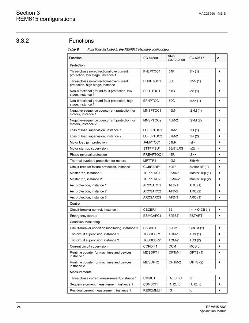
3.3.2 FunctionsTable 9: Functions included in the REM615 standard configuration
Function IEC 61850 ANSI C37.2-2008 IEC 60617 A
Protection
Three-phase non-directional overcurrent protection, low stage, instance 1
PHLPTOC1 51P 3I> (1) ●
Three-phase non-directional overcurrent protection, high stage, instance 1
PHHPTOC1 50P 3I>> (1) ●
Non-directional ground-fault protection, low stage, instance 1
EFLPTOC1 51G Io> (1) ●
Non-directional ground-fault protection, high stage, instance 1
EFHPTOC1 50G Io>> (1) ●
Negative-sequence overcurrent protection for motors, instance 1
MNSPTOC1 46M-1 I2>M (1) ●
Negative-sequence overcurrent protection for motors, instance 2
MNSPTOC2 46M-2 I2>M (2) ●
Loss of load supervision, instance 1 LOFLPTUC1 37M-1 3I< (1) ●
Loss of load supervision, instance 2 LOFLPTUC2 37M-2 3I< (2) ●
Motor load jam protection JAMPTOC1 51LR Ist> ●
Motor start-up supervision STTPMSU1 66/51LRS Is2t n< ●
Phase reversal protection PREVPTOC1 46R I2>> ●
Thermal overload protection for motors MPTTR1 49M 3Ith>M ●
Circuit breaker failure protection, instance 1 CCBRBRF1 50BF 3I>/Io>BF (1) ●
Master trip, instance 1 TRPPTRC1 86/94-1 Master Trip (1) ●
Master trip, instance 2 TRPPTRC2 86/94-2 Master Trip (2) ●
Arc protection, instance 1 ARCSARC1 AFD-1 ARC (1) ●
Arc protection, instance 2 ARCSARC2 AFD-2 ARC (2) ●
Arc protection, instance 3 ARCSARC3 AFD-3 ARC (3) ●
Control
Circuit-breaker control, instance 1 CBCBR1 52 I <-> O CB (1) ●
Emergency startup ESMGAPC1 62EST ESTART ●
Condition Monitoring
Circuit-breaker condition monitoring, instance 1 SSCBR1 52CM CBCM (1) ●
Trip circuit supervision, instance 1 TCSSCBR1 TCM-1 TCS (1) ●
Trip circuit supervision, instance 2 TCSSCBR2 TCM-2 TCS (2) ●
Current circuit supervision CCRDIF1 CCM MCS 3I ●
Runtime counter for machines and devices, instance 1
MDSOPT1 OPTM-1 OPTS (1) ●
Runtime counter for machines and devices, instance 2
MDSOPT2 OPTM-2 OPTS (2) ●
Measurements
Three-phase current measurement, instance 1 CMMU1 IA, IB, IC 3I ●
Sequence current measurement, instance 1 CSMSQI1 I1, I2, I0 I1, I2, I0 ●
Residual current measurement, instance 1 RESCMMU1 IG Io ●

1MAC259901-MB B Section 3REM615 configurations
REM615 ANSI 25Application Manual
Other functions
Minimum pulse timer (2 pcs), instance 1 TPGAPC1 TP-1 TP (1) ●
Minimum pulse timer (2 pcs), instance 2 TPGAPC2 TP-2 TP (2) ●
Minimum pulse timer (2 pcs), instance 3 TPGAPC3 TP-3 TP (3) ●
Minimum pulse timer (2 pcs), instance 4 TPGAPC4 TP-4 TP (4) ●
Pulse timer (8 pcs), instance 1 PTGAPC1 PT-1 PT (1) ●
Pulse timer (8 pcs), instance 2 PTGAPC2 PT-2 PT (2) ●
Time delay off (8 pcs), instance 1 TOFGAPC1 TOF-1 TOF (1) ●
Time delay off (8 pcs), instance 2 TOFGAPC2 TOF-2 TOF (2) ●
Time delay on (8 pcs), instance 1 TONGAPC1 TON -1 TON (1) ●
Time delay on (8 pcs), instance 2 TONGAPC2 TON -2 TON (2) ●
Set reset (8 pcs), instance 1 SRGAPC1 SR-1 SR (1) ●
Set reset (8 pcs), instance 2 SRGAPC2 SR-2 SR (2) ●
Move (8 pcs), instance 1 MVGAPC1 MV-1 MV (1) ●
Move (8 pcs), instance 2 MVGAPC2 MV-2 MV (2) ●
Logging
Disturbance recorder RDRE1 DFR - ●
Fault recorder FLTMSTA1 FR - ●
Sequence event recorder SER SER - ●
Function IEC 61850 ANSI C37.2-2008 IEC 60617 A

Section 3 1MAC259901-MB B
REM615 configurations
26 REM615 ANSIApplication Manual
3.3.3 Default Input/Output (I/O) assignments Table 10: Analog input connections for CTs
Table 11: Binary input connections
Table 12: Binary output connections
Table 13: High speed binary output connections*
Analog input Default usage Connector pinsX120 - IA Current input for phase IA X120 – 7, 8
X120 - IB Current input for phase IB X120 – 9,10
X120 - IC Current input for phase IC X120 – 11,12
X120 - IG Ground current input IG X120 – 13,14
Binary input Default usage Connector pinsX120-BI1 Emergency start enable X120-1, 2
X120-BI2 Circuit breaker closed position X120-3, 2
X120-BI3 Circuit breaker open position X120-4, 2
X120-BI4 X120-5,6
Binary output Default usage Connector pinsX100-PO1 Close circuit breaker X100 – 6,7
X100-PO2 Breaker failure backup trip to upstream breaker X100 – 8,9
X100-SO1 X100 – 11/12, 10
X100-SO2 X100 – 13, 14
X100-PO3 Open circuit breaker / Master Trip -1 X100 – 15,19
X100-PO4 Open circuit breaker / Master Trip -2 X100 – 20,24
X110-SO1* X110 – 15/16, 14
X110-SO2* X110 – 18/19, 17
X110-SO3* X110 – 21/22, 20
X110-SO4* X110 – 23,24
*Not available if IED has been ordered with High speed binary output (HSO) card
Binary input Default usage Connector pinsX110-HSO1 Open circuit breaker / Master Trip -1 X110 – 15,16
X110-HSO2 Trip from ARC-2 protection X110 – 19,20
X110-HSO3 Trip from ARC-3 protection X110 – 23,24
*Available only if IED has been ordered with High speed binary output (HSO) card
1MAC259901-MB B Section 3REM615 configurations
REM615 ANSI 27Application Manual
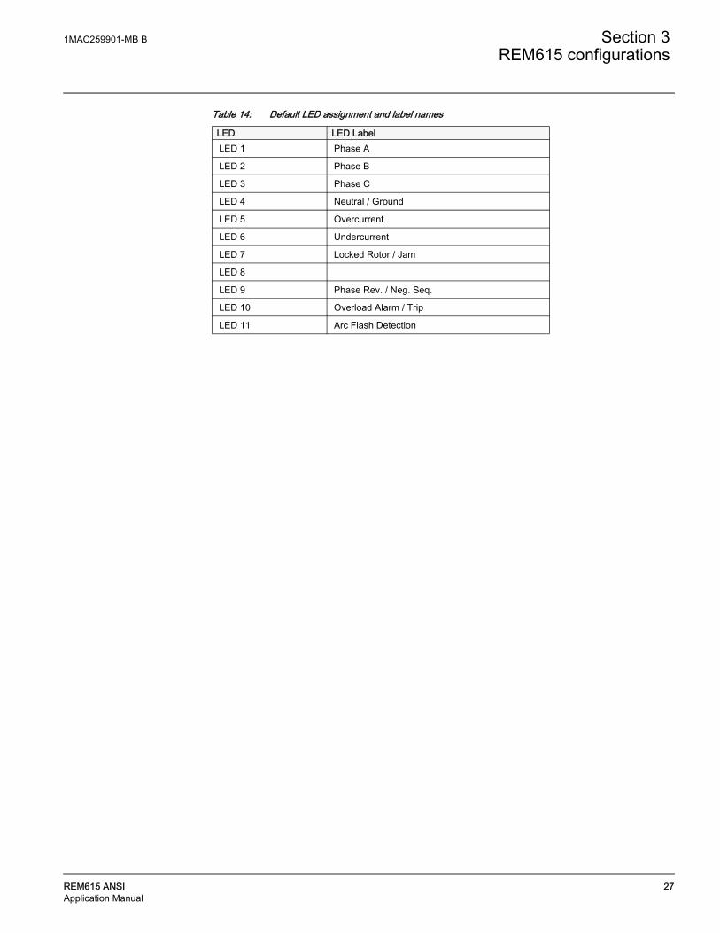
Table 14: Default LED assignment and label names
LED LED LabelLED 1 Phase A
LED 2 Phase B
LED 3 Phase C
LED 4 Neutral / Ground
LED 5 Overcurrent
LED 6 Undercurrent
LED 7 Locked Rotor / Jam
LED 8
LED 9 Phase Rev. / Neg. Seq.
LED 10 Overload Alarm / Trip
LED 11 Arc Flash Detection

Section 3 1MAC259901-MB B
REM615 configurations
28 REM615 ANSIApplication Manual
3.3.4 Typical connection diagram

1MAC259901-MB B Section 3REM615 configurations
REM615 ANSI 29Application Manual
3.3.5 Functional diagramsThe functional diagrams describe the default input, output, alarm LED and function-to-function connections. The default connections can be viewed with and changed with PCM 600 according to the application requirements, if necessary.
The analog channels, measurements from CTs, have fixed connections to the different function blocks inside the IED's standard configuration.
The signal marked with IA, IB and IC represents the three phase currents. The signal IG represents the measured ground current.
REM615 offers si different settings group which the user can set based on individual needs. Each group can then, be activated/ deactivated by using the setting group settings available in REM615.
3.3.6 Functional diagrams for protectionThe functional diagrams describe the IED's protection functionality in detail and according to the factory set default connections.
Two, three-phase overcurrent protection (51P and 50P) stages are provided for overcurrent and short-circuit protection of motor. 51P can be used for overcurrent protection and 50P for the short-circuit protection. Apart from three-phase overcurrent protection, motor jam protection (51LR) is also available for protecting the motor under locked rotor or mechanical jam situations during running conditions.
The operation of 51P and 50P is not blocked as default by any functionality and so setting should be set such as to avoid unnecessary false trip or alarm. 51LR is blocked by the motor startup protection (66/51LRS) to avoid operation of 51LR during motor starting condition. The operation of 51P and 50P is connected to alarm LED 5, and 51LR (along with motor startup protection) is connected to alarm LED 7.
Figure 6: Three phase overcurrent and motor jam protectionAlarm LEDs 1, 2 and 3 are configured so as to indicate which phase has resulted into tripping of 50P and 51P. Overcurrent faults in Phase A, B and C is mapped to Alarm LEDs 1, 2 and 3 respectively.

Section 3 1MAC259901-MB B
REM615 configurations
30 REM615 ANSIApplication Manual
Two non-directional ground-fault protection (51G and 50G) stages are provided to detect phase-to-ground faults that may be a result of, for example, insulation ageing or sudden failure of insulation.
The operation of 51G and 50G is not blocked as default by any functionality. The operation of ground-fault protection functions is connected to alarm LED 4.
Figure 7: Non-directional ground fault protectionConfiguration also includes pickup alarm, the pickup outputs from 50P, 51P, 50G and 51G are connected together to have a combined overcurrent pickup alarm which is connected to disturbance recorder as default.
Figure 8: Overcurrent pickup alarmsTwo negative-sequence overcurrent protection (46M-1 and 46M-2) stages are provided for phase unbalance protection. These functions are used to protect the motor against phase unbalance caused by, for example, a broken conductor. Excessive negative sequence current results into overheating of the motor eventually resulting into insulation damage.
This configuration also includes phase reversal protection (46R), based on the calculated negative phase-sequence current. It detects too high negative phase sequence current values during motor start up, caused by incorrectly connected phases, which in turn causes the motor to rotate in the reverse direction.
The operation of 46M-1, 46M-2 and 46R is not blocked as default by any functionality. The operation of these protection functions is connected to alarm LED 9.

1MAC259901-MB B Section 3REM615 configurations
REM615 ANSI 31Application Manual
Figure 9: Negative sequence and phase reversal protection
The thermal overload protection function (49M) detects short and long term overloads under varying load conditions. When the emergency start request is issued for the emergency start function, it activates the corresponding input of the thermal overload function. When the thermal overload function has issued a restart blocking, which inhibits the closing of the breaker during machine overload condition; the emergency start request removes this blocking and enables the user to start the motor again.
The alarm and operation of thermal overload protection function is connected to alarm LED 10.
Figure 10: Motor thermal overload protection
With the motor startup supervision function (66/51LRS) the starting of the motor is supervised by monitoring three-phase currents or the status of the energizing circuit breaker of the motor. It is also possible to connect the speed switch to determine the locked rotor situation.
The operation of 66/51LRS (along with motor jam protection) is connected to alarm LED 7.
When the emergency start request is activated by 62EST and if 66/51LRS is in lockout state, which inhibits motor starting, the lockout is deactivated and emergency starting is available.
By default 46M-2 is not configured to give trip to the circuit breaker.
Section 3 1MAC259901-MB B
REM615 configurations
32 REM615 ANSIApplication Manual
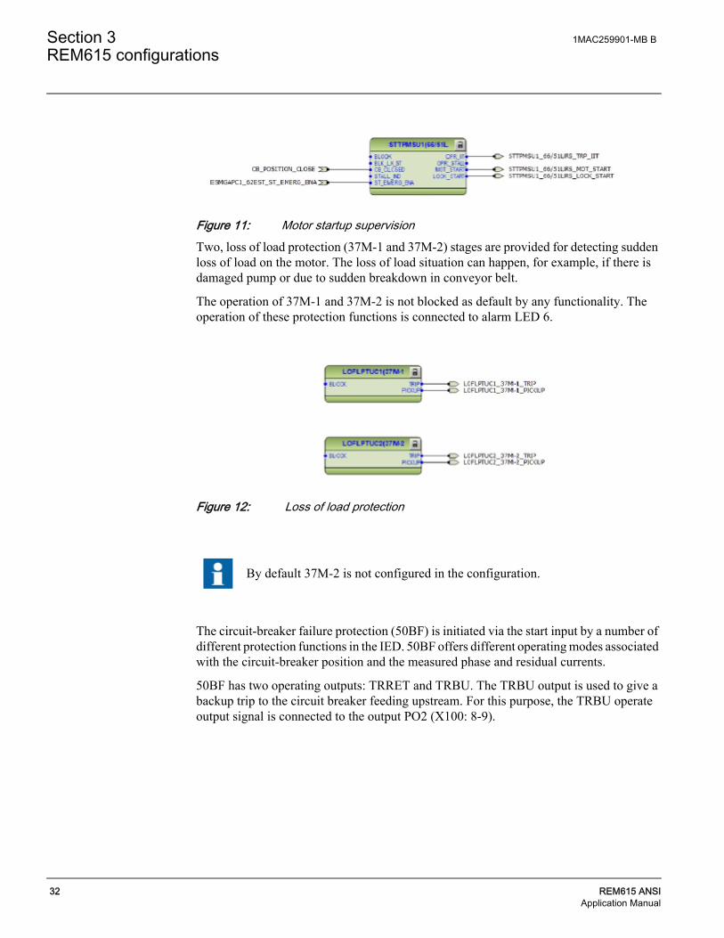
Figure 11: Motor startup supervisionTwo, loss of load protection (37M-1 and 37M-2) stages are provided for detecting sudden loss of load on the motor. The loss of load situation can happen, for example, if there is damaged pump or due to sudden breakdown in conveyor belt.
The operation of 37M-1 and 37M-2 is not blocked as default by any functionality. The operation of these protection functions is connected to alarm LED 6.
Figure 12: Loss of load protection
The circuit-breaker failure protection (50BF) is initiated via the start input by a number of different protection functions in the IED. 50BF offers different operating modes associated with the circuit-breaker position and the measured phase and residual currents.
50BF has two operating outputs: TRRET and TRBU. The TRBU output is used to give a backup trip to the circuit breaker feeding upstream. For this purpose, the TRBU operate output signal is connected to the output PO2 (X100: 8-9).
By default 37M-2 is not configured in the configuration.

1MAC259901-MB B Section 3REM615 configurations
REM615 ANSI 33Application Manual
Figure 13: Circuit breaker failure protection
Three arc protection (ARC-1, ARC-2 and ARC-3) stages are included as an optional function. The arc protection offers individual function blocks for three ARC sensors that can be connected to the IED. Each arc protection function block has two different operation modes, with or without the phase and residual current check.
Figure 14: Arc protection
Trip signal from AFD-1 is connected to Master trip 1, available at PO3 (X100: 15-19). Whereas the trip signal from AFD-2 and AFD-3 is connected to master trip 2, available at PO4 (X100: 20-24). The operation of these protection functions is connected to alarm LED 11.
If the IED has been ordered with high speed binary outputs, then trip signal from AFD-2 and AFD-3 are connected directly to high speed output HS02 (X110:19-20) and HS03(X110:23-24) respectively.
The TRRET operate output can be used for retripping its own circuit breaker through the Master Trip again. However this is not connected in present configuration.

Section 3 1MAC259901-MB B
REM615 configurations
34 REM615 ANSIApplication Manual
Two master trip logics (86/94-1 and 86/94-2) are provided as a trip command collector. 86/94-1 collects the trip signals from 51P, 50P, 51G, 50G, 46M-1, 37M-1, 46R, 51LR, 66/51LRS and ARC-1 protection functions and is connected to trip output contact PO3 (X100:16-19) and also to high speed output HS01 (X110:15-16) for IEDs ordered with high speed binary output cards.
Open control commands to the circuit breaker from the local or remote is also connected directly to the output PO3 (X100:16-19) from circuit breaker control (52) function block.
86/94-2 collects the trip signals from ARC-2 and ARC-3 protection functions and is connected to trip output contact PO4 (X100:20-24).
Figure 15: Master trip logic 1
Figure 16: Master trip logic 2
86/94-1 and 86/94-2 provides the lockout/latching function, event generation and the trip signal duration setting. If the lockout operation mode is selected, one binary input can be reassigned to the RST_LKOUT input of the Master Trip to enable eternal reset with a push button.
3.3.7 Functional diagrams for control functions The emergency start function (62EST) allows motor startups although the restart inhibit is activated. The emergency start is enabled for ten minutes after the selected binary input BI1 (X120:1:2) is energized. On the rising edge of the emergency start signal:

1MAC259901-MB B Section 3REM615 configurations
REM615 ANSI 35Application Manual
• Calculated thermal level is set slightly below the restart inhibit level to allow at least one motor startup.
• Value of the cumulative startup time counter 66/51LRS is set slightly below the set restart inhibit value to allow at least one motor startup.
A new emergency start cannot be made until the emergency start signal has been reset and the emergency start time of 10 minutes has expired
Figure 17: Emergency startThe circuit breaker closing is enabled when the ENA_CLOSE input is activated. The input can be activated by the configuration logic, which is a combination of the disconnector or breaker truck and ground switch position status and the status of the Master Trip logics and gas pressure alarm and circuit-breaker spring charging. The OK_POS output of the CBXCBR can also be connected to the interlocking logic enabling the breaker closing, thus breaker closing in intermediate state can be prevented. With the present configuration, the activation of ENA_CLOSE input is configured using only Master Trip logic 86/94-1 and 86/94-2 i.e. the circuit breaker cannot be closed in case master trip is active.
Configuration also includes motor restart inhibit logic. When the motor restart is inhibited, the BLK_CLOSE input is activated and closing of the breaker is not possible. When all conditions of the circuit breaker closing are fulfilled, the EE_CL output of the 52 is activated and PO1 output (X100:6-7) is closed if closing command is given.
The motor restart inhibit is activated when there is
• An active trip command or
• Motor startup supervision has issued lockout or
• Motor unbalance function has issued restart blocking or
• Motor thermal overload function has issued restart blocking
The ITL_BYPASS input can be used, for example, to always enable the closing of the circuit breaker when the circuit breaker truck is in the test position, despite of the interlocking conditions being active when the circuit breaker truck is closed in service position.

Section 3 1MAC259901-MB B
REM615 configurations
36 REM615 ANSIApplication Manual
Figure 18: Circuit breaker control
3.3.8 Functional diagrams for condition monitoring Two trip circuit monitoring (TCM-1 and TCM-2) stages are provided to supervise the trip circuit of the circuit breaker connected at PO3 (X100:15-19) and PO4 (X100:20-24).
Figure 19: Trip circuit monitoring
The TCM-1 and TCM-2 functions are blocked by 86/94-1, 86/94-2 and the circuit-breaker open position signal.
If the ENA_CLOSE and BLK_CLOSE signals are completely removed from the breaker control function block 52 with PCM600, the function assumes that the breaker close commands are allowed continuously.
By default TCM-1 and TCM-2 are not configured in the configuration.
By default it is expected that there is no eternal resistor in the circuit breaker tripping/closing coil circuit connected parallel with circuit breaker normally open/closed auxiliary contact.

1MAC259901-MB B Section 3REM615 configurations
REM615 ANSI 37Application Manual
A failure in current measuring circuits is detected by current circuit supervision function (CCM). When a failure is detected, function activates and can be used to block protection functions which operates using calculated sequence component currents for example 46M, thus avoiding mal-operation.
Figure 20: Current circuit supervision
Two motor run time counter (OPTM-1 and OPTM-2) stages are provided to calculate and present the total number of motor running hours; these running hours are incremented when the energizing circuit breaker is in closed position.
Figure 21: Run time counter
The circuit breaker condition monitoring function (52CM) supervises the circuit breaker status based on the binary input information connected and measured current levels. The function introduces various supervision alarms.
By default the FAIL output from CCM function is only connected to disturbance recorder
By default OPTM-1 and OPTM-2 are not configured in the configuration.

Section 3 1MAC259901-MB B
REM615 configurations
38 REM615 ANSIApplication Manual
Figure 22: Circuit breaker condition monitoring
3.3.9 Functional diagrams for MeasurementsThe phase current inputs to the IED are measured by three-phase current measurement (IA, IB, IC) function block. The current input is connected to the X120 card in the back panel. Similarly the sequence and residual current are measured by sequence current measurement (I1, I2, I0) and residual current measurement (IG) function blocks respectively.
The measurements can be seen from the LHMI and is available using the measurement option in the menu selection. Based on the settings, IA, IB, IC and IG function blocks can generate low alarm/warning, high alarm/warning signals for the measured current values.
Figure 23: Current measurements
By default 52CM is not configured in the configuration.

1MAC259901-MB B Section 3REM615 configurations
REM615 ANSI 39Application Manual
3.3.10 Functional diagrams for other functions Configuration also includes other miscellaneous basic functions which are not configured, but can be used for creating general purpose logics. These functions include:
• Four instance of Minimum Pulse Timer TP-1, TP-2, TP-3 and TP-4,
• Two instance of Pulse Timer PT-1 and PT-2,
• Two instance of Time delay off TOF-1 and TOF-2,
• Two instance of Time delay on TON-1 and TON-2,
• Two instance of Set reset logic SR-1 and SR-2 and
• Two instance of Move logic MV-1 and MV-2
3.3.11 Functional diagrams for logging functions The disturbance recorder DFR consists of 64 channels. However, as default, a few channels are connected to trigger the digital fault recorder are as shown in Figure 24. More connections can be made as per individual need. Also, when disturbance recorder is the trigger, the analog values available at the analog inputs are recorded by fault recorder FR.

Section 3 1MAC259901-MB B
REM615 configurations
40 REM615 ANSIApplication Manual
Figure 24: 64 channel Disturbance and fault recorder
3.3.12 Functional diagrams for I/O and Alarm LEDs The default binary I/O connected in the configuration and Alarm LEDs are indicated in to Alarm LEDs

1MAC259901-MB B Section 3REM615 configurations
REM615 ANSI 41Application Manual
Figure 25: Binary inputs
Figure 26: Binary outputs
High speed binary outputs (HSO) are available only if IED with High speed binary card has been ordered.

Section 3 1MAC259901-MB B
REM615 configurations
42 REM615 ANSIApplication Manual
Figure 27: Alarm LEDs

1MAC259901-MB B Section 3REM615 configurations
REM615 ANSI 43Application Manual
3.4 Standard Configuration for Order Code Functional Application B
3.4.1 ApplicationsThis standard configuration is mainly intended for medium to large circuit breaker controlled induction motors with differential protection and six RTD inputs. This standard configuration can be applied also for contactor controlled motors.
The IED with this standard configuration is delivered from the factory with default settings and parameters. The end-user flexibility for incoming, outgoing and internal signal designation within the IED enable this configuration to be further adapted to different primary power system layouts and the related functionality needs by modifying the internal functionality using PCM600.

Section 3 1MAC259901-MB B
REM615 configurations
44 REM615 ANSIApplication Manual
3.4.2 FunctionsTable 15: Functions included in the REM615 standard configuration
Function IEC 61850 ANSI C37.2-2008 IEC 60617 B
Protection
Three-phase non-directional overcurrent protection, low stage, instance 1
PHLPTOC1 51P 3I> (1) ●
Three-phase non-directional overcurrent protection, high stage, instance 1
PHHPTOC1 50P 3I>> (1) ●
Non-directional ground-fault protection, low stage, instance 1
EFLPTOC1 51G Io> (1) ●
Non-directional ground-fault protection, high stage, instance 1
EFHPTOC1 50G Io>> (1) ●
Negative-sequence overcurrent protection for motors, instance 1
MNSPTOC1 46M-1 I2>M (1) ●
Negative-sequence overcurrent protection for motors, instance 2
MNSPTOC2 46M-2 I2>M (2) ●
Loss of load supervision, instance 1 LOFLPTUC1 37M-1 3I< (1) ●
Loss of load supervision, instance 2 LOFLPTUC2 37M-2 3I< (2) ●
Motor load jam protection JAMPTOC1 51LR Ist> ●
Motor start-up supervision STTPMSU1 66/51LRS Is2t n< ●
Phase reversal protection PREVPTOC1 46R I2>> ●
Thermal overload protection for motors MPTTR1 49M 3Ith>M ●
Motor differential protection MPDIF1 87M 3dl>M ●
Circuit breaker failure protection, instance 1 CCBRBRF1 50BF 3I>/Io>BF (1) ●
Master trip, instance 1 TRPPTRC1 86/94-1 Master Trip (1) ●
Master trip, instance 2 TRPPTRC2 86/94-2 Master Trip (2) ●
Arc protection, instance 1 ARCSARC1 AFD-1 ARC (1) ●
Arc protection, instance 2 ARCSARC2 AFD-2 ARC (2) ●
Arc protection, instance 3 ARCSARC3 AFD-3 ARC (3) ●
Multi-purpose protection, instance 1 1) MAPGAPC1 MAP-1 MAP (1) ●
Multi-purpose protection, instance 2 1) MAPGAPC2 MAP-2 MAP (2) ●
Multi-purpose protection, instance 3 1) MAPGAPC3 MAP-3 MAP (3) ●
Control
Circuit-breaker control, instance 1 CBCBR1 52 I <-> O CB (1)
●
Emergency startup ESMGAPC1 62EST ESTART ●
Condition Monitoring
Circuit-breaker condition monitoring, instance 1 SSCBR1 52CM CBCM (1) ●
Trip circuit supervision, instance 1 TCSSCBR1 TCM-1 TCS (1) ●
Trip circuit supervision, instance 2 TCSSCBR2 TCM-2 TCS (2) ●
Runtime counter for machines and devices, instance 1
MDSOPT1 OPTM-1 OPTS (1) ●
Runtime counter for machines and devices, instance 2
MDSOPT2 OPTM-2 OPTS (2) ●

1MAC259901-MB B Section 3REM615 configurations
REM615 ANSI 45Application Manual
Measurements
Three-phase current measurement, instance 1 CMMU1 IA, IB, IC-1 3I ●
Three-phase current measurement, instance 2 CMMU2 IA, IB, IC-2 3I(B) ●
Sequence current measurement, instance 1 CSMSQI1 I1, I2, I0-1 I1, I2, I0 ●
Sequence current measurement, instance 2 CSMSQI2 I1, I2, I0-2 I1, I2, I0(B) ●
Residual current measurement, instance 1 RESCMMU1 IG Io ●
6 RTD + 2 mA measurement RGGIOX130 X130 (RTD) ●
Other Functions
Minimum pulse timer (2 pcs), instance 1 TPGAPC1 TP-1 TP (1) ●
Minimum pulse timer (2 pcs), instance 2 TPGAPC2 TP-2 TP (2) ●
Minimum pulse timer (2 pcs), instance 3 TPGAPC3 TP-3 TP (3) ●
Minimum pulse timer (2 pcs), instance 4 TPGAPC4 TP-4 TP (4) ●
Pulse timer (8 pcs), instance 1 PTGAPC1 PT-1 PT (1) ●
Pulse timer (8 pcs), instance 2 PTGAPC2 PT-2 PT (2) ●
Time delay off (8 pcs), instance 1 TOFGAPC1 TOF-1 TOF (1) ●
Time delay off (8 pcs), instance 2 TOFGAPC2 TOF-2 TOF (2) ●
Time delay on (8 pcs), instance 1 TONGAPC1 TON -1 TON (1) ●
Time delay on (8 pcs), instance 2 TONGAPC2 TON -2 TON (2) ●
Set reset (8 pcs), instance 1 SRGAPC1 SR-1 SR (1) ●
Set reset (8 pcs), instance 2 SRGAPC2 SR-2 SR (2) ●
Move (8 pcs), instance 1 MVGAPC1 MV-1 MV (1) ●
Move (8 pcs), instance 2 MVGAPC2 MV-2 MV (2) ●
Logging Functions
Disturbance recorder RDRE1 DFR - ●
Fault recorder FLTMSTA1 FR - ●
Sequence event recorder SER SER - ●
Notes1) Multi-purpose protection is used for, for example, RTD/mA
Function IEC 61850 ANSI C37.2-2008 IEC 60617 B

Section 3 1MAC259901-MB B
REM615 configurations
46 REM615 ANSIApplication Manual
3.4.3 Default Input/Output (I/O) assignments Table 16: Analog input connections for CTs
Table 17: Analog input connections for RTDs
Table 18: Binary input connections
Analog input Default usage Connector pinsX120 - IA(2) Current input for phase IA, neutral side X120 – 1,2
X120 - IB(2) Current input for phase IB, neutral side X120 – 3, 4
X120 - IC(2) Current input for phase IC, neutral side X120 – 5, 6
X120 - IA(1) Current input for phase IA, line side X120 – 7, 8
X120 - IB(1) Current input for phase IB, line side X120 – 9,10
X120 – IC(1) Current input for phase IC, line side X120 – 11,12
X120 - IG Ground current input IG X120 – 13,14
RTD input Default usage Connector pinsX130-RTD1 Stator temperature, Phase A X130-5,6,11
X130-RTD2 Stator temperature, Phase B X130-7,8,11
X130-RTD3 Stator temperature, Phase C X130-9,10, 11
X130-RTD4 Bearing temperature, Motor X130-13,14,12
X130-RTD5 Bearing temperature, Load X130-15,16,12
X130-RTD6 Ambient temperature X130-17,18,12
Binary input Default usage Connector pinsX110-BI1 X110-1, 2
X110-BI2 X110-3, 4
X110-BI3 X110-5, 6
X110-BI4 X110-7, 6
X110-BI5 X110-8, 9
X110-BI6 Emergency start enable X110-10,9
X110-BI7 Circuit breaker closed position X110-11, 12
X110-BI8 Circuit breaker open position X110-13, 12

1MAC259901-MB B Section 3REM615 configurations
REM615 ANSI 47Application Manual
Table 19: Binary output connections
Table 20: High speed binary output connections*
Table 21: Default LED assignment and label names
Binary output Default usage Connector pinsX100-PO1 Close circuit breaker X100 – 6,7
X100-PO2 Breaker failure backup trip to upstream breaker X100 – 8,9
X100-SO1 X100 – 11/12, 10
X100-SO2 X100 – 13, 14
X100-PO3 Open circuit breaker / Master Trip -1 X100 – 15,19
X100-PO4 Open circuit breaker / Master Trip -2 X100 – 20,24
X110-SO1* Stator Alarm RTD X110 – 15/16, 14
X110-SO2* Bearing Alarm RTD X110 – 18/19, 17
X110-SO3* X110 – 21/22, 20
X110-SO4* X110 – 23,24
*Not available if IED has been ordered with High speed binary output (HSO) card
Binary output Default usage Connector pinsX110-HSO1 Open circuit breaker / Master Trip -1 X110 – 15,16
X110-HSO2 Trip from ARC-2 protection X110 – 19,20
X110-HSO3 Trip from ARC-3 protection X110 – 23,24
*Available only if IED has been ordered with High speed binary output (HSO) card
LED LED labelLED 1 Phase A
LED 2 Phase B
LED 3 Phase C
LED 4 Neutral / Ground
LED 5 Overcurrent
LED 6 Undercurrent
LED 7 Locked Rotor/Load Jam
LED 8 Differential
LED 9 Phase Rev. / Neg. Seq.
LED 10 Overload Alarm/Trip
LED 11 Arc Flash Detection

Section 3 1MAC259901-MB B
REM615 configurations
48 REM615 ANSIApplication Manual
3.4.4 Typical connection diagrams
1MAC259901-MB B Section 3REM615 configurations
REM615 ANSI 49Application Manual
3.4.5 Functional diagramsThe functional diagrams describe the default input, output, RTD inputs, alarm LED and function-to-function connections. The default connections can be viewed with and changed with PCM 600 according to the application requirements, if necessary.
The analog channels, measurements from CTs, have fixed connections to the different function blocks inside the IED’s standard configuration.
The signal marked with IA, IB and IC represents the three phase currents on line side, whereas the signal marked with IA2, IB2 and IC2 represents the three phase current on neutral side. The signal IG represents the measured ground current on line side.
REM615 offers si different settings group which the user can set based on individual needs. Each group can then, be activated/ deactivated by using the setting group settings available in REM615.
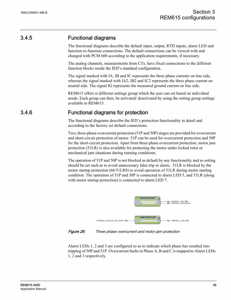
3.4.6 Functional diagrams for protectionThe functional diagrams describe the IED’s protection functionality in detail and according to the factory set default connections.
Two, three-phase overcurrent protection (51P and 50P) stages are provided for overcurrent and short-circuit protection of motor. 51P can be used for overcurrent protection and 50P for the short-circuit protection. Apart from three-phase overcurrent protection, motor jam protection (51LR) is also available for protecting the motor under locked rotor or mechanical jam situations during running conditions.
The operation of 51P and 50P is not blocked as default by any functionality and so setting should be set such as to avoid unnecessary false trip or alarm. 51LR is blocked by the motor startup protection (66/51LRS) to avoid operation of 51LR during motor starting condition. The operation of 51P and 50P is connected to alarm LED 5, and 51LR (along with motor startup protection) is connected to alarm LED 7.
Figure 28: Three phase overcurrent and motor jam protection
Alarm LEDs 1, 2 and 3 are configured so as to indicate which phase has resulted into tripping of 50P and 51P. Overcurrent faults in Phase A, B and C is mapped to Alarm LEDs 1, 2 and 3 respectively.

Section 3 1MAC259901-MB B
REM615 configurations
50 REM615 ANSIApplication Manual
Two non-directional ground-fault protection (51G and 50G) stages are provided to detect phase-to-ground faults that may be a result of, for example, insulation ageing or sudden failure of insulation.
The operation of 51G and 50G is not blocked as default by any functionality. The operation of ground-fault protection functions is connected to alarm LED 4.
Figure 29: Non-directional ground fault protection
Configuration also includes pickup alarm, the pickup outputs from 50P, 51P, 50G and 51G are connected together to have a combined overcurrent pickup alarm which is connected to disturbance recorder as default.
Figure 30: Overcurrent pickup alarms
Two negative-sequence overcurrent protection (46M-1 and 46M-2) stages are provided for phase unbalance protection. These functions are used to protect the motor against phase unbalance caused by, for example, a broken conductor. Excessive negative sequence current results into overheating of the motor eventually resulting into insulation damage.
This configuration also includes phase reversal protection (46R), based on the calculated negative phase-sequence current. It detects too high negative phase sequence current values during motor start up, caused by incorrectly connected phases, which in turn causes the motor to rotate in the reverse direction.
The operation of 46M-1, 46M-2 and 46R is not blocked as default by any functionality. The operation of these protection functions is connected to alarm LED 9.

1MAC259901-MB B Section 3REM615 configurations
REM615 ANSI 51Application Manual
Figure 31: Negative sequence and phase reversal protection
The thermal overload protection function (49M) detects short and long term overloads under varying load conditions. When the emergency start request is issued for the emergency start function, it activates the corresponding input of the thermal overload function. When the thermal overload function has issued a restart blocking, which inhibits the closing of the breaker during machine overload condition; the emergency start request removes this blocking and enables the user to start the motor again.
The alarm and operation of thermal overload protection function is connected to alarm LED 10.
Figure 32: Motor thermal overload protection
With the motor startup supervision function (66/51LRS) the starting of the motor is supervised by monitoring three-phase currents or the status of the energizing circuit breaker of the motor. It is also possible to connect the speed switch to determine the locked rotor situation.
The operation of 66/51LRS (along with motor jam protection) is connected to alarm LED 7.
When the emergency start request is activated by 62EST and if 66/51LRS is in lockout state, which inhibits motor starting, the lockout is deactivated and emergency starting is available.
By default 46M-2 is not configured in the configuration.
Section 3 1MAC259901-MB B
REM615 configurations
52 REM615 ANSIApplication Manual
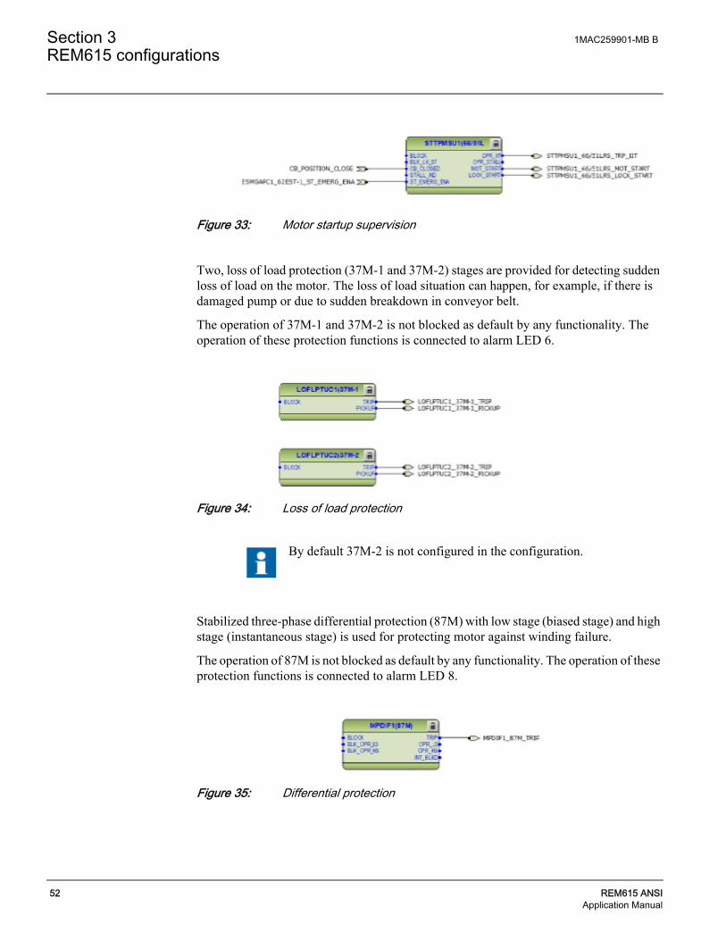
Figure 33: Motor startup supervision
Two, loss of load protection (37M-1 and 37M-2) stages are provided for detecting sudden loss of load on the motor. The loss of load situation can happen, for example, if there is damaged pump or due to sudden breakdown in conveyor belt.
The operation of 37M-1 and 37M-2 is not blocked as default by any functionality. The operation of these protection functions is connected to alarm LED 6.
Figure 34: Loss of load protection
Stabilized three-phase differential protection (87M) with low stage (biased stage) and high stage (instantaneous stage) is used for protecting motor against winding failure.
The operation of 87M is not blocked as default by any functionality. The operation of these protection functions is connected to alarm LED 8.
Figure 35: Differential protection
By default 37M-2 is not configured in the configuration.

1MAC259901-MB B Section 3REM615 configurations
REM615 ANSI 53Application Manual
The circuit-breaker failure protection (50BF) is initiated via the start input by a number of different protection functions in the IED. 50BF offers different operating modes associated with the circuit-breaker position and the measured phase and residual currents.
50BF has two operating outputs: TRRET and TRBU. The TRBU output is used to give a backup trip to the circuit breaker feeding upstream. For this purpose, the TRBU operate output signal is connected to the output PO2 (X100: 8-9).
Figure 36: Circuit breaker failure protection
Three multipurpose analog protection (MAP-1, MAP-2, and MAP-3) functions are included in the configuration which can be used as an under protection or overprotection. In the present configuration these functions are used to provide thermal protection using RTD/mA .
Temperature of the motor windings U, V and W are measured with inputs RTD-1 (X130:5,6,11), RTD-2 (X130:7,8,11) and RTD-3 (X130:9,10,11). Measured values are connected from function X130 (RTD) to MAX-3 function. Maximum temperature value is then connected to the multipurpose analog protection block MAP-1.
Motor bearing and load temperature can be measured with inputs RTD-4 (X130:13,14,12) and RTD-5 (X130:15,16,12). The protection functionality for these temperatures are provided by MAP-2 and MAP-3 functions respectively.
Motor ambient temperature can be measured with input RTD6 (X130:17,18,12) and it is connected to the 49M.
Trip signals from MAP-1 and MAP-2 are connected directly to binary output S01 (X110:14,15), and S02 (X110:17,18) respectively if the IED has been ordered without high speed binary output.
The TRRET operate output can be used for retripping its own circuit breaker through the Master Trip again. However this is not connected in present configuration.
.The MAX-3 function always selects the maximum quantity from the connected inputs. It must be verified that input connections start from input1. Otherwise the function generates error code.

Section 3 1MAC259901-MB B
REM615 configurations
54 REM615 ANSIApplication Manual
Figure 37: General purpose protection function
Three arc protection (AFD-1, AFD-2 and AFD-3) functions are included as an optional function. The arc protection offers individual function blocks for three ARC sensors that can be connected to the IED. Each arc protection function block has two different operation modes, with or without the phase and residual current check.
Figure 38: Arc protection
It is mandatory to connect IN1 input of MAX-3 function. Leaving IN1 input disconnected will result in wrong maximum output at OUT.

1MAC259901-MB B Section 3REM615 configurations
REM615 ANSI 55Application Manual
Trip signal from AFD-1 is connected to Master trip 1, available at PO3 (X100: 15-19). Whereas the trip signal from AFD-2 and AFD-3 is connected to master trip 2, available at PO4 (X100: 20-24). The operation of these protection functions is connected to alarm LED 11.
If the IED has been ordered with high speed binary outputs, then trip signal from AFD-2 and AFD-3 are connected directly to high speed output HS02 (X110:19-20) and HS03(X110:23-24) respectively.
Two master trip logics (86/94-1 and 86/94-2) are provided as a trip command collector. 86/94-1 collects the trip signals from 51P, 50P, 51G, 50G, 46M-1, 37M-1, 46R, 51LR, 66/51LRS, 87M and ARC-1 protection functions and is connected to trip output contact PO3 (X100:16-19) and also to high speed output HS01 (X110:15-16) for IEDs ordered with high speed binary output cards.
Open control commands to the circuit breaker from the local or remote is also connected directly to the output PO3 (X100:16-19) from circuit breaker control (52) function block.
86/94-2 collects the trip signals from ARC-2 and ARC-3 protection functions and is connected to trip output contact PO4 (X100:20-24).
Figure 39: Master trip logic 1
Figure 40: Master trip logic 2
86/94-1 and 86/94-2 provides the lockout/latching function, event generation and the trip signal duration setting. If the lockout operation mode is selected, one binary input can be reassigned to the RST_LKOUT input of the Master Trip to enable eternal reset with a push button.

Section 3 1MAC259901-MB B
REM615 configurations
56 REM615 ANSIApplication Manual
3.4.7 Functional diagrams for control functions The emergency start function (62EST) allows motor startups although the restart inhibit is activated. The emergency start is enabled for ten minutes after the selected binary input BI1 (X120:1:2) is energized. On the rising edge of the emergency start signal:
• Calculated thermal level is set slightly below the restart inhibit level to allow at least one motor startup.
• Value of the cumulative startup time counter 66/51LRS is set slightly below the set restart inhibit value to allow at least one motor startup.
• Operate values of the MAP-1 function is increased by set value.
A new emergency start cannot be made until the emergency start signal has been reset and the emergency start time of 10 minutes has expired
Figure 41: Emergency start
The circuit breaker closing is enabled when the ENA_CLOSE input is activated. The input can be activated by the configuration logic, which is a combination of the disconnector or breaker truck and ground switch position status and the status of the Master Trip logics and gas pressure alarm and circuit-breaker spring charging. The OK_POS output of the CBXCBR can also be connected to the interlocking logic enabling the breaker closing, thus breaker closing in intermediate state can be prevented. With the present configuration, the activation of ENA_CLOSE input is configured using only Master Trip logic 86/94-1 and 86/94-2 i.e. the circuit breaker cannot be closed in case master trip is active.
Configuration also includes motor restart inhibit logic. When the motor restart is inhibited, the BLK_CLOSE input is activated and closing of the breaker is not possible. When all conditions of the circuit breaker closing are fulfilled, the EE_CL output of the 52 is activated and PO1 output (X100:6-7) is closed if closing command is given.
The motor restart inhibit is activated when there is
• An active trip command or
• Motor startup supervision has issued lockout or
• Motor unbalance function has issued restart blocking or
• Motor thermal overload function has issued restart blocking
The ITL_BYPASS input can be used, for example, to always enable the closing of the circuit breaker when the circuit breaker truck is in the test position, despite of the

1MAC259901-MB B Section 3REM615 configurations
REM615 ANSI 57Application Manual
interlocking conditions being active when the circuit breaker truck is closed in service position.
Figure 42: Circuit breaker control
3.4.8 Functional diagrams for condition monitoring Two trip circuit monitoring (TCM-1 and TCM-2) stages are provided to supervise the trip circuit of the circuit breaker connected at PO3 (X100:15-19) and PO4 (X100:20-24).
Figure 43: Trip circuit monitoring
The TCM-1 and TCM-2 functions are blocked by 86/94-1, 86/94-2 and the circuit-breaker open position signal.
If the ENA_CLOSE and BLK_CLOSE signals are completely removed from the breaker control function block 52 with PCM600, the function assumes that the breaker close commands are allowed continuously.

Section 3 1MAC259901-MB B
REM615 configurations
58 REM615 ANSIApplication Manual
Two motor run time counter (OPTM-1 and OPTM-2) stages are provided to calculate and present the total number of motor running hours; these running hours are incremented when the energizing circuit breaker is in closed position.
Figure 44: Run-time counter
The circuit breaker condition monitoring function (52CM) supervises the circuit breaker status based on the binary input information connected and measured current levels. The function introduces various supervision alarms.
Figure 45: Circuit breaker condition monitoring
By default TCM-1 and TCM-2 are not configured in the configuration.
By default it is expected that there is no eternal resistor in the circuit breaker tripping/closing coil circuit connected parallel with circuit breaker normally open/closed auxiliary contact.
By default OPTM-1 and OPTM-2 are not configured in the configuration.

1MAC259901-MB B Section 3REM615 configurations
REM615 ANSI 59Application Manual
3.4.9 Functional diagrams for MeasurementsThe three-phase currents from phase and neutral side of the motor are measured by three-phase current measurement (IA, IB, IC and IA, IB, IC(2)) function block respectively. The current inputs are connected to the X120 card in the back panel. Similarly the phase and neutral side sequence current component are measured by sequence current measurement (I1, I2, I0 and I1, I2, I0(2)) function block respectively. The phase side ground current is measurement by residual current functional block (IG).
The measurements can be seen from the LHMI and is available using the measurement option in the menu selection. Based on the settings, ‘IA, IB, IC’, ‘IA, IB, IC(2)’ and IG function blocks can generate low alarm/warning, high alarm/warning signals for the measured current values.
Figure 46: Current measurements
3.4.10 Functional diagrams for other functions Configuration also includes other miscellaneous basic functions which are not configured, but can be used for creating general purpose logics. These functions include:
• Four instance of Minimum Pulse Timer TP-1, TP-2, TP-3 and TP-4,
• Two instance of Pulse Timer PT-1 and PT-2,
• Two instance of Time delay off TOF-1 and TOF-2,
• Two instance of Time delay on TON-1 and TON-2,
• Two instance of Set reset logic SR-1 and SR-2, and
• Two instance of Move logic MV-1 and MV-2
By default 52CM is not configured in the configuration.

Section 3 1MAC259901-MB B
REM615 configurations
60 REM615 ANSIApplication Manual
3.4.11 Functional diagrams for logging functions The disturbance recorder DFR consists of 64 channels. However, as default, very few channels are connected to trigger the digital fault recorder are as shown in figure. More connections can be made as per individual need. Also when disturbance recorder is trigger the analog values available at the analog inputs are recorded by fault recorder FR.
Figure 47: 64 channel Disturbance and fault recorder
3.4.12 Functional diagrams for I/O and Alarm LEDs The default binary I/O connected in the configuration and Alarm LEDs are indicated in to Alarm LEDs

1MAC259901-MB B Section 3REM615 configurations
REM615 ANSI 61Application Manual
Figure 48: Binary inputs
Figure 49: Binary outputs

Section 3 1MAC259901-MB B
REM615 configurations
62 REM615 ANSIApplication Manual
Figure 50: Alarm LEDs
High speed binary outputs (HSO) are available only if IED with High speed binary card has been ordered.

1MAC259901-MB B Section 3REM615 configurations
REM615 ANSI 63Application Manual
3.5 Standard configuration for order code functional application C and D
3.5.1 ApplicationsThe standard configuration C can be used for medium breaker controlled induction motors with current, voltage and frequency protection. The standard configuration D can be used for medium breaker controlled induction motors with current, voltage, and frequency protection with two RTD inputs. Both these configuration can also be applied for contactor controlled motors
The IED with this standard configuration is delivered from the factory with default settings and parameters. The end-user flexibility for incoming, outgoing and internal signal designation within the IED enable this configuration to be further adapted to different primary power system layouts and the related functionality needs by modifying the internal functionality using PCM600.

Section 3 1MAC259901-MB B
REM615 configurations
64 REM615 ANSIApplication Manual
3.5.2 FunctionsTable 22: Functions included in the REM615 standard configuration
Function IEC 61850 ANSI C37.2-2008 IEC 60617 C D
Protection
Three-phase non-directional overcurrent protection, low stage, instance 1
PHLPTOC1 51P 3I> (1) ● ●
Three-phase non-directional overcurrent protection, high stage, instance 1
PHHPTOC1 50P 3I>> (1) ● ●
Non-directional ground-fault protection, low stage, instance 1
EFLPTOC1 51G Io> (1) ● ●
Non-directional ground-fault protection, high stage, instance 1
EFHPTOC1 50G Io>> (1) ● ●
Directional ground-fault protection, low stage, instance 1
DEFLPDEF1 67/51N Io> -> (1) ●1)
●1)
Residual overvoltage protection, instance 1 ROVPTOV1 59G Uo> (1) ● ●
Three-phase undervoltage protection, instance 1
PHPTUV1 27 3U< (1) ● ●
Three-phase overvoltage protection, instance 1
PHPTOV1 59 3U> (1) ● ●
Positive-sequence undervoltage protection, instance 1
PSPTUV1 27PS U1< (1) ● ●
Negative-sequence overvoltage protection, instance 1
NSPTOV1 47 U2> (1) ● ●
Frequency protection, instance 1 FRPFRQ1 81 f>/f<,df/dt (1)
● ●
Negative-sequence overcurrent protection for motors, instance 1
MNSPTOC1 46M-1 I2>M (1) ● ●
Negative-sequence overcurrent protection for motors, instance 2
MNSPTOC2 46M-2 I2>M (2) ● ●
Loss of load supervision, instance 1 LOFLPTUC1 37M-1 3I< (1) ● ●
Loss of load supervision, instance 2 LOFLPTUC2 37M-2 3I< (2) ● ●
Motor load jam protection JAMPTOC1 51LR Ist> ● ●
Motor start-up supervision STTPMSU1 66/51LRS Is2t n< ● ●
Phase reversal protection PREVPTOC1 46R I2>> ● ●
Thermal overload protection for motors MPTTR1 49M 3Ith>M ● ●
Circuit breaker failure protection, instance 1
CCBRBRF1 50BF 3I>/Io>BF (1)
● ●
Master trip, instance 1 TRPPTRC1 86/94-1 Master Trip (1)
● ●
Master trip, instance 2 TRPPTRC2 86/94-2 Master Trip (2)
● ●
Arc protection, instance 1 ARCSARC1 AFD-1 ARC (1) ● ●
Arc protection, instance 2 ARCSARC2 AFD-2 ARC (2) ● ●
Arc protection, instance 3 ARCSARC3 AFD-3 ARC (3) ● ●
Multi-purpose protection, instance 1 MAPGAPC1 MAP-1 MAP (1) - ● 2)
Multi-purpose protection, instance 2 MAPGAPC2 MAP-2 MAP (2) - ● 2)

1MAC259901-MB B Section 3REM615 configurations
REM615 ANSI 65Application Manual
Multi-purpose protection, instance 3 MAPGAPC3 MAP-3 MAP (3) - ● 2)
Control
Circuit-breaker control, instance 1 CBCBR1 52 I <-> O CB (1)
● ●
Emergency startup ESMGAPC1 62EST ESTART ● ●
Condition Monitoring
Circuit-breaker condition monitoring, instance 1
SSCBR1 52CM CBCM (1) ● ●
Trip circuit supervision, instance 1 TCSSCBR1 TCM-1 TCS (1) ● ●
Trip circuit supervision, instance 2 TCSSCBR2 TCM-2 TCS (2) ● ●
Current circuit supervision CCRDIF1 CCM MCS 3I ● ●
Fuse failure supervision, instance 1 SEQRFUF1 60 FUSEF (1) ● ●
Runtime counter for machines and devices, instance 1
MDSOPT1 OPTM-1 OPTS (1) ● ●
Runtime counter for machines and devices, instance 2
MDSOPT2 OPTM-2 OPTS (2) ● ●
Measurements
Three-phase current measurement, instance 1
CMMU1 IA, IB, IC-1 3I ● ●
Sequence current measurement, instance 1
CSMSQI1 I1, I2, I0-1 I1, I2, I0 ● ●
Residual current measurement, instance 1 RESCMMU1 IG Io ● ●
Three-phase voltage measurement, instance 1
VMMU1 VA, VB, VC 3U ● ●
Residual voltage measurement, instance 1 RESVMMU1 VG Uo ● ●
Sequence voltage measurement, instance 1
VSMSQI1 V1, V2, V0 U1, U2, U0 ● ●
Single-phase power and energy measurement, instance 1
SPEMMU1 SP, SE SP, SE ● ●
Three-phase power and energy measurement, instance 1
PEMMU1 P, E P, E ● ●
2 RTD +1 mA ARGGIOX130 X130 (AIM+RTD)
- ●
Frequency measurement, instance 1 FMMU1 f f ● ●
Other Functions
Minimum pulse timer (2 pcs), instance 1 TPGAPC1 TP-1 TP (1) ● ●
Minimum pulse timer (2 pcs), instance 2 TPGAPC2 TP-2 TP (2) ● ●
Minimum pulse timer (2 pcs), instance 3 TPGAPC3 TP-3 TP (3) ● ●
Minimum pulse timer (2 pcs), instance 4 TPGAPC4 TP-4 TP (4) ● ●
Pulse timer (8 pcs), instance 1 PTGAPC1 PT-1 PT (1) ● ●
Pulse timer (8 pcs), instance 2 PTGAPC2 PT-2 PT (2) ● ●
Time delay off (8 pcs), instance 1 TOFGAPC1 TOF-1 TOF (1) ● ●
Time delay off (8 pcs), instance 2 TOFGAPC2 TOF-2 TOF (2) ● ●
Time delay on (8 pcs), instance 1 TONGAPC1 TON -1 TON (1) ● ●
Function IEC 61850 ANSI C37.2-2008 IEC 60617 C D

Section 3 1MAC259901-MB B
REM615 configurations
66 REM615 ANSIApplication Manual
3.5.3 Default Input/Output (I/O) assignmentsTable 23: Analog input connections for CTs
Table 24: Analog input connections for VTs
Table 25: Analog input connections for RTDs*
Time delay on (8 pcs), instance 2 TONGAPC2 TON -2 TON (2) ● ●
Set reset (8 pcs), instance 1 SRGAPC1 SR-1 SR (1) ● ●
Set reset (8 pcs), instance 2 SRGAPC2 SR-2 SR (2) ● ●
Move (8 pcs), instance 1 MVGAPC1 MV-1 MV (1) ● ●
Move (8 pcs), instance 2 MVGAPC2 MV-2 MV (2) ● ●
Logging Functions
Disturbance recorder RDRE1 DFR - ● ●
Fault recorder FLTMSTA1 FR - ● ●
Sequence event recorder SER SER - ● ●
Notes1) Vo calculated and negative sequence voltage selectable by parameter, V2 as default Io selectable by parameter, I2 as default.2) Multi-purpose protection is used for, for example, RTD/mA
Function IEC 61850 ANSI C37.2-2008 IEC 60617 C D
Analog input Default usage Connector pinsX120 – IA Current input for phase IA X120 – 7, 8
X120 – IB Current input for phase IB X120 – 9,10
X120 – IC Current input for phase IC X120 – 11,12
X120 - IG Ground current input IG X120 – 13,14
Analog input Default usage Connector pinsX130 – VA Voltage input for phase VA X130 – 11,12
X130 – VB Voltage input for phase VB X130 – 13,14
X130 – VC Voltage input for phase VC X130 – 15,16
X130 - VG Ground voltage input VG X130 – 17,18
RTD input Default usage Connector pinsX130-RTD1 Stator Temperature X130-3,4,5
X130-RTD2 Bearing Temperature X130-6,7,8
*Available only for IED ordered with Application “D”

1MAC259901-MB B Section 3REM615 configurations
REM615 ANSI 67Application Manual
Table 26: Binary input connections
Table 27: Binary output connections
Table 28: High speed binary output connections*
Binary input Default usage Connector pinsX120-BI1 Emergency start enable X120-1, 2
X120-BI2 Circuit breaker closed position X120-3, 2
X120-BI3 Circuit breaker open position X120-4, 2
X120-BI4 X120-5,6
Binary output Default usage Connector pinsX100-PO1 Close circuit breaker X100 – 6,7
X100-PO2 Breaker failure backup trip to upstream breaker X100 – 8,9
X100-SO1 X100 – 11/12, 10
X100-SO2 X100 – 13, 14
X100-PO3 Open circuit breaker / Master Trip -1 X100 – 15,19
X100-PO4 Open circuit breaker / Master Trip -2 X100 – 20,24
X110-SO1* Stator Alarm RTD X110 – 15/16, 14
X110-SO2* Bearing Alarm RTD X110 – 18/19, 17
X110-SO3* X110 – 21/22, 20
X110-SO4* X110 – 23,24
*Not available if IED has been ordered with High speed binary output (HSO) card
Binary output Default usage Connector pinsX110-HSO1 Open circuit breaker / Master Trip -1 X110 – 15,16
X110-HSO2 Trip from ARC-2 protection X110 – 19,20
X110-HSO3 Trip from ARC-3 protection X110 – 23,24
*Available only if IED has been ordered with High speed binary output (HSO) card

Section 3 1MAC259901-MB B
REM615 configurations
68 REM615 ANSIApplication Manual
Table 29: Default LED assignment and label names
LED LED labelLED 1 Phase A
LED 2 Phase B
LED 3 Phase C
LED 4 Neutral / Ground
LED 5 Overcurrent
LED 6 Undercurrent
LED 7 Locked Rotor/Load Jam
LED 8 Voltage/Frequency
LED 9 Phase Rev. / Neg. Seq.
LED 10 Overload Alarm/Trip
LED 11 Arc Flash Detection

1MAC259901-MB B Section 3REM615 configurations
REM615 ANSI 69Application Manual
3.5.4 Typical connection diagrams

Section 3 1MAC259901-MB B
REM615 configurations
70 REM615 ANSIApplication Manual

1MAC259901-MB B Section 3REM615 configurations
REM615 ANSI 71Application Manual
3.5.5 Functional diagramsThe functional diagrams describe the default input, output, RTD inputs, alarm LED and function-to-function connections. The default connections can be viewed with and changed with PCM 600 according to the application requirements, if necessary.
The analog channels, measurements from CTs and PTs, have fixed connections to the different function blocks inside the IED’s standard configuration.
The analog channels are assigned to different functions as shown in the function diagrams. The common signal marked with IA, IB and IC represents the three phase currents. The signal IG represents the measured ground current. Similarly the signal marked with VA, VB and VC represents the three phase voltages. The signal VG represents the measured ground voltage.
REM615 offers si different settings group which the user can set based on individual needs. Each group can then, be activated/ deactivated by using the setting group settings available in REM615.
3.5.6 Functional diagrams for protectionThe functional diagrams describe the IED’s protection functionality in detail and according to the factory set default connections.
Two, three-phase overcurrent protection (51P and 50P) stages are provided for overcurrent and short-circuit protection of motor. 51P can be used for overcurrent protection and 50P for the short-circuit protection. Apart from three-phase overcurrent protection, motor jam protection (51LR) is also available for protecting the motor under locked rotor or mechanical jam situations during running conditions.
The operation of 51P and 50P is not blocked as default by any functionality and so setting should be set such as to avoid unnecessary false trip or alarm. 51LR is blocked by the motor startup protection (66/51LRS) to avoid operation of 51LR during motor starting condition. The operation of 51P and 50P is connected to alarm LED 5, and 51LR (along with motor startup protection) is connected to alarm LED 7.

Section 3 1MAC259901-MB B
REM615 configurations
72 REM615 ANSIApplication Manual
Figure 51: Three phase overcurrent and motor jam protection
Alarm LEDs 1, 2 and 3 are configured so as to indicate which phase has resulted into tripping of 50P and 51P. Overcurrent faults in Phase A, B and C is mapped to Alarm LEDs 1, 2 and 3 respectively.
Two non-directional ground-fault protection (51G and 50G) stages are provided to detect phase-to-ground faults that may be a result of, for example, insulation ageing or sudden failure of insulation.
The operation of 51G and 50G is not blocked as default by any functionality. The operation of ground-fault protection functions is connected to alarm LED 4.
Figure 52: Non-directional ground fault protectionIn addition, there is a directional ground fault protection stage (67/51N) which can also be used as a low stage non-directional ground-fault protection without voltage requirement. However, the residual voltage can help to detect ground faults at a low fault current level selectively and to discriminate the apparent residual current caused, for example, by partial current transformer saturation at motor startup.

1MAC259901-MB B Section 3REM615 configurations
REM615 ANSI 73Application Manual
67/51N is blocked by fuse failure supervision (60) function, to avoid mal operation in case of failure in voltage secondary circuit. The operation of ground-fault protection functions is connected to alarm LED 4.
Figure 53: Directional ground fault protectionConfiguration also includes pickup alarm, the pickup outputs from 50P, 51P, 50G, 51G and 67/51N are connected together to have a combined overcurrent pickup alarm which is connected to disturbance recorder as default.
Figure 54: Overcurrent pickup alarmsFor voltage protection, three-phase undervoltage (27), positive-sequence undervoltage (27PS), three-phase overvoltage (59), residual overvoltage (59G) and negative-sequence overvoltage (47) protection functions are offered. The 27, 27PS and 47 protection functions are blocked if the fuse failure is detected.
The positive-sequence undervoltage and negative-sequence overvoltage protections are included to protect the machine against single-phasing, excessive unbalance between phases and abnormal phase order.

Section 3 1MAC259901-MB B
REM615 configurations
74 REM615 ANSIApplication Manual
Figure 55: Voltage protection
Frequency protection (81) function is also available in the configuration. 81 can be set to operate as under frequency or over frequency or as rate of change of frequency protection.
The operation of voltage and frequency protection functions is connected to alarm LED 8.
Figure 56: Frequency protectionTwo negative-sequence overcurrent protection (46M-1 and 46M-2) stages are provided for phase unbalance protection. These functions are used to protect the motor against phase unbalance caused by, for example, a broken conductor. Excessive negative sequence current results into overheating of the motor eventually resulting into insulation damage.
This configuration also includes phase reversal protection (46R), based on the calculated negative phase-sequence current. It detects too high negative phase sequence current values during motor start up, caused by incorrectly connected phases, which in turn causes the motor to rotate in the reverse direction.
By default 59G is not configured in the configuration.

1MAC259901-MB B Section 3REM615 configurations
REM615 ANSI 75Application Manual
The operation of 46M-1, 46M-2 and 46R is not blocked as default by any functionality. The operation of these protection functions is connected to alarm LED 9.
Figure 57: Negative sequence and phase reversal protection
The thermal overload protection function (49M) detects short and long term overloads under varying load conditions. When the emergency start request is issued for the emergency start function, it activates the corresponding input of the thermal overload function. When the thermal overload function has issued a restart blocking, which inhibits the closing of the breaker during machine overload condition; the emergency start request removes this blocking and enables the user to start the motor again.
The alarm and operation of thermal overload protection functions is connected to alarm LED 10.
Figure 58: Motor thermal overload protectionWith the motor startup supervision function (66/51LRS) the starting of the motor is supervised by monitoring three-phase currents or the status of the energizing circuit breaker of the motor. It is also possible to connect the speed switch to determine the locked rotor situation.
By default 46M-2 is not configured in the configuration.

Section 3 1MAC259901-MB B
REM615 configurations
76 REM615 ANSIApplication Manual
The operation of 66/51LRS (along with motor jam protection) is connected to alarm LED 7.
When the emergency start request is activated by 62EST and if 66/51LRS is in lockout state, which inhibits motor starting, the lockout is deactivated and emergency starting is available.
Figure 59: Motor startup supervisionTwo, loss of load protection (37M-1 and 37M-2) stages are provided for detecting sudden loss of load on the motor. The loss of load situation can happen, for example, if there is damaged pump or due to sudden breakdown in conveyor belt.
The operation of 37M-1 and 37M-2 is not blocked as default by any functionality. The operation of these protection functions is connected to alarm LED 6.
Figure 60: Loss of load protection
The circuit-breaker failure protection (50BF) is initiated via the start input by a number of different protection functions in the IED. 50BF offers different operating modes associated with the circuit-breaker position and the measured phase and residual currents.
50BF has two operating outputs: TRRET and TRBU. The TRBU output is used to give a backup trip to the circuit breaker feeding upstream. For this purpose, the TRBU operate output signal is connected to the output PO2 (X100: 8-9).
By default 37M-2 is not configured in the configuration.

1MAC259901-MB B Section 3REM615 configurations
REM615 ANSI 77Application Manual
Figure 61: Circuit breaker failure protection
Three multipurpose analog protection (MAP-1, MAP-2, and MAP-3) functions are included as an optional function, in the configuration which can be used as an under protection or overprotection. In the present configuration MAP-1 and MAP-2 functions are used to provide thermal protection using RTD/mA, where as MAP-3 is not configured.
Temperature of the motor stator is measured with inputs RTD-1 (X130:3,4,5) and is connected to the multipurpose analog protection block MAP-1.
Figure 62: General purpose protection function and associated RTD inputsRotor temperature is measured with inputs RTD-2 (X130:6,7,8). The protection functionality for rotor temperatures is provided by MAP-2 functions.
Trip signals from MAP-1 and MAP-2 are connected directly to binary output S01 (X110:14,15), and S02 (X110:17,18) respectively if the IED has been ordered without high speed binary output.
The TRRET operate output can be used for retripping its own circuit breaker through the Master Trip again. However this is not connected in present configuration.
By default MAP-3 is not configured in the configuration.

Section 3 1MAC259901-MB B
REM615 configurations
78 REM615 ANSIApplication Manual
Three arc protection (AFD-1, AFD-2 and AFD-3) functions are included as an optional function. The arc protection offers individual function blocks for three ARC sensors that can be connected to the IED. Each arc protection function block has two different operation modes, with or without the phase and residual current check.
Figure 63: Arc protectionTrip signal from AFD-1 is connected to Master trip 1, available at PO3 (X100: 15-19). Whereas the trip signal from AFD-2 and AFD-3 is connected to master trip 2, available at PO4 (X100: 20-24). The operation of these protection functions is connected to alarm LED 11.
If the IED has been ordered with high speed binary outputs, then trip signal from AFD-2 and AFD-3 are connected directly to high speed output HS02 (X110:19-20) and HS03(X110:23-24) respectively.
Two master trip logics (86/94-1 and 86/94-2) are provided as a trip command collector. 86/94-1 collects the trip signals from 51P, 50P, 51G, 50G, 67/51N, 46M-1, 37M-1, 46R, 51LR, 66/51LRS, 27, 27PS, 47, 59, 81 and ARC-1 protection functions and is connected to trip output contact PO3 (X100:16-19) and also to high speed output HS01 (X110:15-16) for IEDs ordered with high speed binary output cards.
Open control commands to the circuit breaker from the local or remote is also connected directly to the output PO3 (X100:16-19) from circuit breaker control (52) function block.
86/94-2 collects the trip signals from ARC-2 and ARC-3 protection functions and is connected to trip output contact PO4 (X100:20-24).

1MAC259901-MB B Section 3REM615 configurations
REM615 ANSI 79Application Manual
Figure 64: Master trip logic 1
Figure 65: Master trip logic 286/94-1 and 86/94-2 provides the lockout/latching function, event generation and the trip signal duration setting. If the lockout operation mode is selected, one binary input can be reassigned to the RST_LKOUT input of the Master Trip to enable eternal reset with a push button.
3.5.7 Functional diagrams for control functions The emergency start function (62EST) allows motor startups although the restart inhibit is activated. The emergency start is enabled for ten minutes after the selected binary input BI1 (X120:1,2) is energized. On the rising edge of the emergency start signal:
• Calculated thermal level is set slightly below the restart inhibit level to allow at least one motor startup.
• Value of the cumulative startup time counter 66/51LRS is set slightly below the set restart inhibit value to allow at least one motor startup.
A new emergency start cannot be made until the emergency start signal has been reset and the emergency start time of 10 minutes has expired
Figure 66: Emergency start

Section 3 1MAC259901-MB B
REM615 configurations
80 REM615 ANSIApplication Manual
The circuit breaker closing is enabled when the ENA_CLOSE input is activated. The input can be activated by the configuration logic, which is a combination of the disconnector or breaker truck and ground switch position status and the status of the Master Trip logics and gas pressure alarm and circuit-breaker spring charging. The OK_POS output of the CBXCBR can also be connected to the interlocking logic enabling the breaker closing, thus breaker closing in intermediate state can be prevented. With the present configuration, the activation of ENA_CLOSE input is configured using only Master Trip logic 86/94-1 and 86/94-2 i.e. the circuit breaker cannot be closed in case master trip is active.
Configuration also includes motor restart inhibit logic. When the motor restart is inhibited, the BLK_CLOSE input is activated and closing of the breaker is not possible. When all conditions of the circuit breaker closing are fulfilled, the EE_CL output of the 52 is activated and PO1 output (X100:6-7) is closed if closing command is given.
The motor restart inhibit is activated when there is
• An active trip command or
• Motor startup supervision has issued lockout or
• Motor unbalance function has issued restart blocking or
• Motor thermal overload function has issued restart blocking
The ITL_BYPASS input can be used, for example, to always enable the closing of the circuit breaker when the circuit breaker truck is in the test position, despite of the interlocking conditions being active when the circuit breaker truck is closed in service position.
Figure 67: Circuit breaker control
If the ENA_CLOSE and BLK_CLOSE signals are completely removed from the breaker control function block 52 with PCM600, the function assumes that the breaker close commands are allowed continuously.

1MAC259901-MB B Section 3REM615 configurations
REM615 ANSI 81Application Manual
3.5.8 Functional diagrams for condition monitoring Two trip circuit monitoring (TCM-1 and TCM-2) stages are provided to supervise the trip circuit of the circuit breaker connected at PO3 (X100:15-19) and PO4 (X100:20-24).
Figure 68: Trip circuit monitoring
The TCM-1 and TCM-2 functions are blocked by 86/94-1, 86/94-2 and the circuit-breaker open position signal.
A failure in current measuring circuits is detected by current circuit supervision function (CCM). When a failure is detected, function activates and can be used to block protection functions which operates using calculated sequence component currents for example 46M, thus avoiding mal-operation.
Figure 69: Current circuit supervision
Similar to CCM function, a failure in voltage measurement circuit is detected by fuse failure supervision function (60). The function is used to block the voltage protection and directional protection functions at failures in the secondary circuits between the voltage transformer and IED to avoid mal operation.
By default TCM-1 and TCM-2 are not configured in the configuration.
By default it is expected that there is no eternal resistor in the circuit breaker tripping/closing coil circuit connected parallel with circuit breaker normally open/closed auxiliary contact.
By default the FAIL output from CCM function is only connected to disturbance recorder

Section 3 1MAC259901-MB B
REM615 configurations
82 REM615 ANSIApplication Manual
Figure 70: Fuse failure supervision
Two motor run time counter (OPTM-1 and OPTM-2) stages are provided to calculate and present the total number of motor running hours; these running hours are incremented when the energizing circuit breaker is in closed position.
Figure 71: Run-time counter
The circuit breaker condition monitoring function (52CM) supervises the circuit breaker status based on the binary input information connected and measured current levels. The function introduces various supervision alarms.
Figure 72: Circuit breaker condition monitoring
By default OPTM-1 and OPTM-2 are not configured in the configuration.
Outputs from 52CM function are not configured in the configuration.

1MAC259901-MB B Section 3REM615 configurations
REM615 ANSI 83Application Manual
3.5.9 Functional diagrams for MeasurementsThe phase current and voltage inputs to the IED are measured by three-phase current measurement (IA, IB, IC) and three-phase voltage measurement (VA, VB, VC) function block. The current and voltage inputs are connected to the X120 and X130 card in the back panel respectively. The sequence and ground currents are measured by sequence current measurement (I1, I2, I0) and ground current measurement (IG) function blocks. Similarly the sequence and ground voltage are measured by sequence voltage measurement (V1, V2, V0) and ground voltage measurement (VG) function blocks respectively.
Apart from current and voltage measurement, configuration also provides single phase (SP, SE) and three phase power and energy measurement (P, E) along with frequency measurement (f) function block.
The measurements can be seen from the LHMI and is available using the measurement option in the menu selection. Based on the settings, ‘IA, IB, IC’, ‘VA, VB, VC’ ‘IG’ and ‘VG’ function blocks can generate low alarm/warning, high alarm/warning signals for the measured current values.
Figure 73: Measurements
3.5.10 Functional diagrams for other functions Configuration also includes other miscellaneous basic functions which are not configured, but can be used for creating general purpose logics. These functions include:
• Four instance of Minimum Pulse Timer TP-1, TP-2, TP-3 and TP-4,
• Two instance of Pulse Timer PT-1 and PT-2,
• Two instance of Time delay off TOF-1 and TOF-2,
• Two instance of Time delay on TON-1 and TON-2,
• Two instance of Set reset logic SR-1 and SR-2, and
• Two instance of Move logic MV-1 and MV-2

Section 3 1MAC259901-MB B
REM615 configurations
84 REM615 ANSIApplication Manual
3.5.11 Functional diagrams for logging functions The disturbance recorder DFR consists of 64 channels. However as default very few channel are connected to trigger the digital fault recorder are as shown in Figure 74. More connection can be made as per individual need. Also when disturbance recorder is trigger the analog values available at the analog inputs are recorded by fault recorder FR.
Figure 74: 64 channel Disturbance and fault recorder
3.5.12 Functional diagrams for I/O and Alarm LEDs The default binary I/O connected in the configuration and Alarm LEDs are indicated in to Alarm LEDs

1MAC259901-MB B Section 3REM615 configurations
REM615 ANSI 85Application Manual
Figure 75: Binary inputs
Figure 76: Binary outputs
High speed binary outputs (HSO) are available only if IED with High speed binary card has been ordered.

Section 3 1MAC259901-MB B
REM615 configurations
86 REM615 ANSIApplication Manual
Figure 77: Alarm LEDs

1MAC259901-MB B Section 3REM615 configurations
REM615 ANSI 87Application Manual
3.6 Standard Configuration for Order Code Functional Application E and F
3.6.1 ApplicationsThe standard configuration E can be used for medium breaker controlled induction motors with current, voltage and frequency protection. The standard configuration F can be used for medium breaker controlled induction motors with current, voltage, and frequency protection with six RTD inputs. Both these configuration can also be applied for contactor controlled motors.
The IED with this standard configuration is delivered from the factory with default settings and parameters. The end-user flexibility for incoming, outgoing and internal signal designation within the IED enable this configuration to be further adapted to different primary power system layouts and the related functionality needs by modifying the internal functionality using PCM600.

Section 3 1MAC259901-MB B
REM615 configurations
88 REM615 ANSIApplication Manual
3.6.2 FunctionsTable 30: Functions included in the REM615 standard configuration
Function IEC 61850 ANSI C37.2-2008 IEC 60617 E F
Protection
Three-phase non-directional overcurrent protection, low stage, instance 1
PHLPTOC1 51P 3I> (1) ● ●
Three-phase non-directional overcurrent protection, high stage, instance 1
PHHPTOC1 50P 3I>> (1) ● ●
Non-directional ground-fault protection, low stage, instance 1
EFLPTOC1 51G Io> (1) ● ●
Non-directional ground-fault protection, high stage, instance 1
EFHPTOC1 50G Io>> (1) ● ●
Directional ground-fault protection, low stage, instance 1
DEFLPDEF1 67/51N Io> -> (1) ●1)
●1)
Residual overvoltage protection, instance 2 ROVPTOV2 59N Uo> (2) ● ●
Three-phase undervoltage protection, instance 1
PHPTUV1 27 3U< (1) ● ●
Three-phase overvoltage protection, instance 1
PHPTOV1 59 3U> (1) ● ●
Positive-sequence undervoltage protection, instance 1
PSPTUV1 27PS U1< (1) ● ●
Negative-sequence overvoltage protection, instance 1
NSPTOV1 47 U2> (1) ● ●
Frequency protection, instance 1 FRPFRQ1 81 f>/f<,df/dt (1)
● ●
Negative-sequence overcurrent protection for motors, instance 1
MNSPTOC1 46M-1 I2>M (1) ● ●
Negative-sequence overcurrent protection for motors, instance 2
MNSPTOC2 46M-2 I2>M (2) ● ●
Loss of load supervision, instance 1 LOFLPTUC1 37M-1 3I< (1) ● ●
Loss of load supervision, instance 2 LOFLPTUC2 37M-2 3I< (2) ● ●
Motor load jam protection JAMPTOC1 51LR Ist> ● ●
Motor start-up supervision STTPMSU1 66/51LRS Is2t n< ● ●
Phase reversal protection PREVPTOC1
46R I2>> ● ●
Thermal overload protection for motors MPTTR1 49M 3Ith>M ● ●
Circuit breaker failure protection, instance 1 CCBRBRF1 50BF 3I>/Io>BF (1)
● ●
Master trip, instance 1 TRPPTRC1 86/94-1 Master Trip (1)
● ●
Master trip, instance 2 TRPPTRC2 86/94-2 Master Trip (2)
● ●
Arc protection, instance 1 ARCSARC1 AFD-1 ARC (1) ● ●
Arc protection, instance 2 ARCSARC2 AFD-2 ARC (2) ● ●
Arc protection, instance 3 ARCSARC3 AFD-3 ARC (3) ● ●
Multi-purpose protection, instance 1 2) MAPGAPC1 MAP-1 MAP (1) - ●
Multi-purpose protection, instance 2 2) MAPGAPC2 MAP-2 MAP (2) - ●
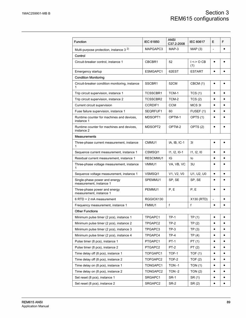
1MAC259901-MB B Section 3REM615 configurations
REM615 ANSI 89Application Manual
Multi-purpose protection, instance 3 2) MAPGAPC3 MAP-3 MAP (3) - ●
Control
Circuit-breaker control, instance 1 CBCBR1 52 I <-> O CB (1)
● ●
Emergency startup ESMGAPC1 62EST ESTART ● ●
Condition Monitoring
Circuit-breaker condition monitoring, instance 1
SSCBR1 52CM CBCM (1) ● ●
Trip circuit supervision, instance 1 TCSSCBR1 TCM-1 TCS (1) ● ●
Trip circuit supervision, instance 2 TCSSCBR2 TCM-2 TCS (2) ● ●
Current circuit supervision CCRDIF1 CCM MCS 3I ● ●
Fuse failure supervision, instance 1 SEQRFUF1 60 FUSEF (1) ● ●
Runtime counter for machines and devices, instance 1
MDSOPT1 OPTM-1 OPTS (1) ● ●
Runtime counter for machines and devices, instance 2
MDSOPT2 OPTM-2 OPTS (2) ● ●
Measurements
Three-phase current measurement, instance 1
CMMU1 IA, IB, IC-1 3I ● ●
Sequence current measurement, instance 1 CSMSQI1 I1, I2, I0-1 I1, I2, I0 ● ●
Residual current measurement, instance 1 RESCMMU1 IG Io ● ●
Three-phase voltage measurement, instance 1
VMMU1 VA, VB, VC 3U ● ●
Sequence voltage measurement, instance 1 VSMSQI1 V1, V2, V0 U1, U2, U0 ● ●
Single-phase power and energy measurement, instance 1
SPEMMU1 SP, SE SP, SE ● ●
Three-phase power and energy measurement, instance 1
PEMMU1 P, E P, E ● ●
6 RTD + 2 mA measurement RGGIOX130 X130 (RTD) - ●
Frequency measurement, instance 1 FMMU1 f f ● ●
Other Functions
Minimum pulse timer (2 pcs), instance 1 TPGAPC1 TP-1 TP (1) ● ●
Minimum pulse timer (2 pcs), instance 2 TPGAPC2 TP-2 TP (2) ● ●
Minimum pulse timer (2 pcs), instance 3 TPGAPC3 TP-3 TP (3) ● ●
Minimum pulse timer (2 pcs), instance 4 TPGAPC4 TP-4 TP (4) ● ●
Pulse timer (8 pcs), instance 1 PTGAPC1 PT-1 PT (1) ● ●
Pulse timer (8 pcs), instance 2 PTGAPC2 PT-2 PT (2) ● ●
Time delay off (8 pcs), instance 1 TOFGAPC1 TOF-1 TOF (1) ● ●
Time delay off (8 pcs), instance 2 TOFGAPC2 TOF-2 TOF (2) ● ●
Time delay on (8 pcs), instance 1 TONGAPC1 TON -1 TON (1) ● ●
Time delay on (8 pcs), instance 2 TONGAPC2 TON -2 TON (2) ● ●
Set reset (8 pcs), instance 1 SRGAPC1 SR-1 SR (1) ● ●
Set reset (8 pcs), instance 2 SRGAPC2 SR-2 SR (2) ● ●
Function IEC 61850 ANSI C37.2-2008 IEC 60617 E F

Section 3 1MAC259901-MB B
REM615 configurations
90 REM615 ANSIApplication Manual
3.6.3 Default Input/Output (I/O) assignmentsTable 31: Analog input connections for CTs
Table 32: Analog input connections for VTs
Table 33: analog input connections for RTDs*
Move (8 pcs), instance 1 MVGAPC1 MV-1 MV (1) ● ●
Move (8 pcs), instance 2 MVGAPC2 MV-2 MV (2) ● ●
Logging Functions
Disturbance recorder RDRE1 DFR - ● ●
Fault recorder FLTMSTA1 FR - ● ●
Sequence event recorder SER SER - ● ●
Notes1) Vo calculated and negative sequence voltage selectable by parameter, V2 as default Io selectable by parameter, I2 as default.2) Multi-purpose protection is used for, for example, RTD/mA.
Function IEC 61850 ANSI C37.2-2008 IEC 60617 E F
Analog input Default usage Connector pinsX120 – IA Current input for phase IA X120 – 7, 8
X120 – IB Current input for phase IB X120 – 9,10
X120 – IC Current input for phase IC X120 – 11,12
X120 - IG Ground current input IG X120 – 13,14
Analog input Default usage Connector pinsX120 – VA Voltage input for phase VA X120 – 1,2
X120 – VB Voltage input for phase VB X120 – 3,4
X120 – VC Voltage input for phase VC X120 – 5,6
RTD input Default usage Connector pinsX130-RTD1 Stator temperature, Phase A X130-5,6,11
X130-RTD2 Stator temperature, Phase B X130-7,8,11
X130-RTD3 Stator temperature, Phase C X130-9,10, 11
X130-RTD4 Bearing temperature, Motor X130-13,14,12
X130-RTD5 Bearing temperature, Load X130-15,16,12
X130-RTD6 Ambient temperature X130-17,18,12
*Available only for IED ordered with Application “F”

1MAC259901-MB B Section 3REM615 configurations
REM615 ANSI 91Application Manual
Table 34: Binary input connections
Table 35: Binary output connections
Table 36: High speed binary output connections*
Binary input Default usage Connector pinsX110-BI1 X110-1, 2
X110-BI2 X110-3, 4
X110-BI3 X110-5, 6
X110-BI4 X110-7, 6
X110-BI5 X110-8, 9
X110-BI6 Emergency start enable X110-10,9
X110-BI7 Circuit breaker closed position X110-11, 12
X110-BI8 Circuit breaker open position X110-13, 12
Binary output Default usage Connector pinsX100-PO1 Close circuit breaker X100 – 6,7
X100-PO2 Breaker failure backup trip to upstream breaker X100 – 8,9
X100-SO1 X100 – 11/12, 10
X100-SO2 X100 – 13, 14
X100-PO3 Open circuit breaker / Master Trip -1 X100 – 15,19
X100-PO4 Open circuit breaker / Master Trip -2 X100 – 20,24
X110-SO1* Stator Alarm RTD X110 – 15/16, 14
X110-SO2* Bearing Alarm RTD X110 – 18/19, 17
X110-SO3* X110 – 21/22, 20
X110-SO4* X110 – 23,24
*Not available if IED has been ordered with High speed binary output (HSO) card
Binary output Default usage Connector pinsX110-HSO1 Open circuit breaker / Master Trip -1 X110 – 15,16
X110-HSO2 Trip from ARC-2 protection X110 – 19,20
X110-HSO3 Trip from ARC-3 protection X110 – 23,24
*Available only if IED has been ordered with High speed binary output (HSO) card
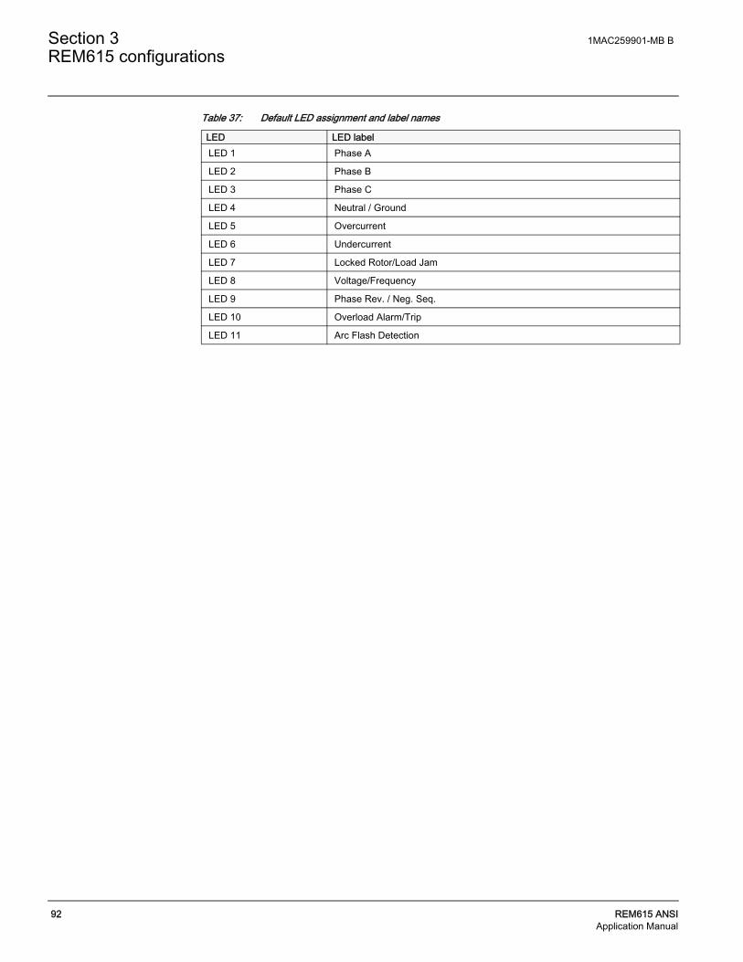
Section 3 1MAC259901-MB B
REM615 configurations
92 REM615 ANSIApplication Manual
Table 37: Default LED assignment and label names
LED LED labelLED 1 Phase A
LED 2 Phase B
LED 3 Phase C
LED 4 Neutral / Ground
LED 5 Overcurrent
LED 6 Undercurrent
LED 7 Locked Rotor/Load Jam
LED 8 Voltage/Frequency
LED 9 Phase Rev. / Neg. Seq.
LED 10 Overload Alarm/Trip
LED 11 Arc Flash Detection

1MAC259901-MB B Section 3REM615 configurations
REM615 ANSI 93Application Manual
3.6.4 Typical connection diagrams

Section 3 1MAC259901-MB B
REM615 configurations
94 REM615 ANSIApplication Manual
3.6.5 Functional diagramsThe functional diagrams describe the default input, output, RTD inputs, alarm LED and function-to-function connections. The default connections can be viewed with and changed with PCM 600 according to the application requirements, if necessary.
The analog channels, measurements from CTs and PTs, have fixed connections to the different function blocks inside the IED’s standard configuration.
The analog channels are assigned to different functions as shown in the function diagrams. The common signal marked with IA, IB and IC represents the three phase currents. The signal IG represents the measured ground current. Similarly the signal marked with VA, VB and VC represents the three phase voltages.
REM615 offers si different settings group which the user can set based on individual needs. Each group can then, be activated/ deactivated by using the setting group settings available in REM615
3.6.6 Functional diagrams for protectionThe functional diagrams describe the IED’s protection functionality in detail and according to the factory set default connections.
Two, three-phase overcurrent protection (51P and 50P) stages are provided for overcurrent and short-circuit protection of motor. 51P can be used for overcurrent protection and 50P for the short-circuit protection. Apart from three-phase overcurrent protection, motor jam protection (51LR) is also available for protecting the motor under locked rotor or mechanical jam situations during running conditions.
The operation of 51P and 50P is not blocked as default by any functionality and so setting should be set such as to avoid unnecessary false trip or alarm. 51LR is blocked by the motor startup protection (66/51LRS) to avoid operation of 51LR during motor starting condition. The operation of 51P and 50P is connected to alarm LED 5, and 51LR (along with motor startup protection) is connected to alarm LED 7.

1MAC259901-MB B Section 3REM615 configurations
REM615 ANSI 95Application Manual
Figure 78: Three phase overcurrent and motor jam protectionAlarm LEDs 1, 2 and 3 are configured so as to indicate which phase has resulted into tripping of 50P and 51P. Overcurrent faults in Phase A, B and C is mapped to Alarm LEDs 1, 2 and 3 respectively.
Two non-directional ground-fault protection (51G and 50G) stages are provided to detect phase-to-ground faults that may be a result of, for example, insulation ageing or sudden failure of insulation. The operation of 51G and 50G is not blocked as default by any functionality. The operation of ground-fault protection functions is connected to alarm LED 4.
Figure 79: Non-directional ground fault protectionIn addition, there is a directional ground fault protection stage (67/51N) which can be also used as a low stage non-directional ground-fault protection without voltage requirement. However, the residual voltage can help to detect ground faults at a low fault current level selectively and to discriminate the apparent residual current caused, for example, by partial current transformer saturation at motor startup.
67/51N is blocked by fuse failure supervision (60) function, to avoid mal operation in case of failure in voltage secondary circuit. The operation of ground-fault protection functions is connected to alarm LED 4.
Figure 80: Directional ground fault protectionConfiguration also includes pickup alarm, the pickup outputs from 50P, 51P, 50G, 51G and 67/51N are connected together to have a combined overcurrent pickup alarm which is connected to disturbance recorder as default.
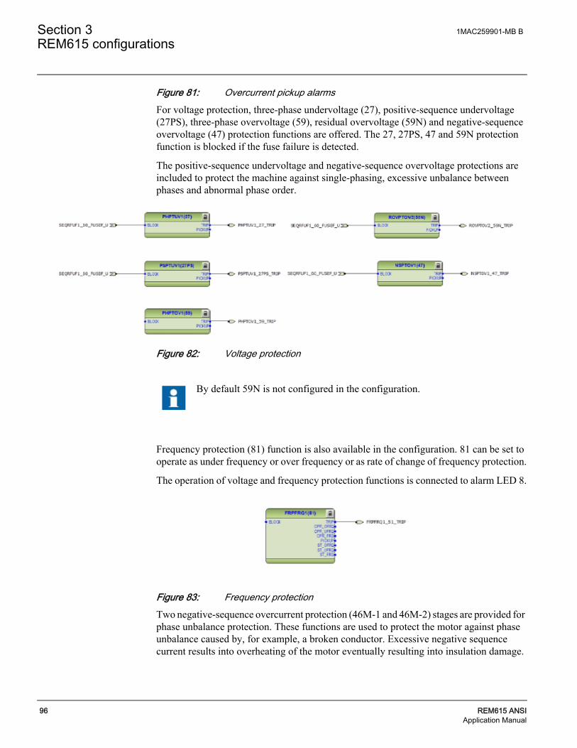
Section 3 1MAC259901-MB B
REM615 configurations
96 REM615 ANSIApplication Manual
Figure 81: Overcurrent pickup alarmsFor voltage protection, three-phase undervoltage (27), positive-sequence undervoltage (27PS), three-phase overvoltage (59), residual overvoltage (59N) and negative-sequence overvoltage (47) protection functions are offered. The 27, 27PS, 47 and 59N protection function is blocked if the fuse failure is detected.
The positive-sequence undervoltage and negative-sequence overvoltage protections are included to protect the machine against single-phasing, excessive unbalance between phases and abnormal phase order.
Figure 82: Voltage protection
Frequency protection (81) function is also available in the configuration. 81 can be set to operate as under frequency or over frequency or as rate of change of frequency protection.
The operation of voltage and frequency protection functions is connected to alarm LED 8.
Figure 83: Frequency protectionTwo negative-sequence overcurrent protection (46M-1 and 46M-2) stages are provided for phase unbalance protection. These functions are used to protect the motor against phase unbalance caused by, for example, a broken conductor. Excessive negative sequence current results into overheating of the motor eventually resulting into insulation damage.
By default 59N is not configured in the configuration.

1MAC259901-MB B Section 3REM615 configurations
REM615 ANSI 97Application Manual
This configuration also includes phase reversal protection (46R), based on the calculated negative phase-sequence current. It detects too high negative phase sequence current values during motor start up, caused by incorrectly connected phases, which in turn causes the motor to rotate in the reverse direction.
The operation of 46M-1, 46M-2 and 46R is not blocked as default by any functionality. The operation of these protection functions is connected to alarm LED 9.
Figure 84: Negative sequence and phase reversal protection
The thermal overload protection function (49M) detects short and long term overloads under varying load conditions. When the emergency start request is issued for the emergency start function, it activates the corresponding input of the thermal overload function. When the thermal overload function has issued a restart blocking, which inhibits the closing of the breaker during machine overload condition; the emergency start request removes this blocking and enables the user to start the motor again.
The alarm and operation of thermal overload protection functions is connected to alarm LED 10.
Figure 85: Motor thermal overload protection
By default 46M-2 is not configured in the configuration.

Section 3 1MAC259901-MB B
REM615 configurations
98 REM615 ANSIApplication Manual
With the motor startup supervision function (66/51LRS) the starting of the motor is supervised by monitoring three-phase currents or the status of the energizing circuit breaker of the motor. It is also possible to connect the speed switch to determine the locked rotor situation.
The operation of 66/51LRS (along with motor jam protection) is connected to alarm LED 7.
When the emergency start request is activated by 62EST and if 66/51LRS is in lockout state, which inhibits motor starting, the lockout is deactivated and emergency starting is available.
Figure 86: Motor startup supervisionTwo, loss of load protection (37M-1 and 37M-2) stages are provided for detecting sudden loss of load on the motor. The loss of load situation can happen, for example, if there is damaged pump or due to sudden breakdown in conveyor belt.
The operation of 37M-1 and 37M-2 is not blocked as default by any functionality. The operation of these protection functions is connected to alarm LED 6.
Figure 87: Loss of load protection
The circuit-breaker failure protection (50BF) is initiated via the start input by a number of different protection functions in the IED. 50BF offers different operating modes associated with the circuit-breaker position and the measured phase and residual currents.
50BF has two operating outputs: TRRET and TRBU. The TRBU output is used to give a backup trip to the circuit breaker feeding upstream. For this purpose, the TRBU operate output signal is connected to the output PO2 (X100: 8-9).
By default 37M-2 is not configured in the configuration.

1MAC259901-MB B Section 3REM615 configurations
REM615 ANSI 99Application Manual
Figure 88: Circuit breaker failure protection and associated binary output
Three multipurpose analog protection (MAP-1, MAP-2, and MAP-3) functions are included in the configuration which can be used as an under protection or overprotection. In the present configuration these functions are used to provide thermal protection using RTD/mA.
Temperature of the motor windings U, V and W are measured with inputs RTD-1 (X130:5,6,11), RTD-2 (X130:7,8,11) and RTD-3 (X130:9,10,11). Measured values are connected from function X130 (RTD) to MAX-3 function. Maximum temperature value is then connected to the multipurpose analog protection block MAP-1.
Motor bearing and load temperature can be measured with inputs RTD-4 (X130:13,14,12) and RTD-5 (X130:15,16,12). The protection functionality for these temperatures are provided by MAP-2 and MAP-3 functions respectively.
Motor ambient temperature can be measured with input RTD6 (X130:17,18,12) and it is connected to the 49M.
Trip signals from MAP-1 is connected directly to binary output S01 (X110:14,15), and from MAP-2 and MAP-3 is connected directly to binary output S02 (X110:17,18) respectively if the IED has been ordered without high speed binary output.
It is mandatory to connect IN1 input of MAX-3 function. Leaving IN1 input disconnected will result in wrong maximum output at OUT.
The TRRET operate output can be used for retripping its own circuit breaker through the Master Trip again. However this is not connected in present configuration.
The MAX-3 function always selects the maximum quantity from the connected inputs. It must be verified that input connections start from input1. Otherwise the function generates error code.

Section 3 1MAC259901-MB B
REM615 configurations
100 REM615 ANSIApplication Manual
Figure 89: General purpose protection function Three arc protection (AFD-1, AFD-2 and AFD-3) functions are included as an optional function. The arc protection offers individual function blocks for three ARC sensors that can be connected to the IED. Each arc protection function block has two different operation modes, with or without the phase and residual current check.
Figure 90: Arc protectionTrip signal from AFD-1 is connected to Master trip 1, available at PO3 (X100: 15-19). Whereas the trip signal from AFD-2 and AFD-3 is connected to master trip 2, available at PO4 (X100: 20-24). The operation of these protection functions is connected to alarm LED 11.
If the IED has been ordered with high speed binary outputs, then trip signal from AFD-2 and AFD-3 are connected directly to high speed output HS02 (X110:19-20) and HS03(X110:23-24) respectively.

1MAC259901-MB B Section 3REM615 configurations
REM615 ANSI 101Application Manual
Two master trip logics (86/94-1 and 86/94-2) are provided as a trip command collector. 86/94-1 collects the trip signals from 51P, 50P, 51G, 50G, 67/51N, 46M-1, 37M-1, 46R, 51LR, 66/51LRS, 27, 27PS, 47, 59, 81 and ARC-1 protection functions and is connected to trip output contact PO3 (X100:16-19) and also to high speed output HS01 (X110:15-16) for IEDs ordered with high speed binary output cards.
Open control commands to the circuit breaker from the local or remote is also connected directly to the output PO3 (X100:16-19) from circuit breaker control (52) function block.
86/94-2 collects the trip signals from ARC-2 and ARC-3 protection functions and is connected to trip output contact PO4 (X100:20-24).
Figure 91: Master trip logic 1
Figure 92: Master trip logic 2
86/94-1 and 86/94-2 provides the lockout/latching function, event generation and the trip signal duration setting. If the lockout operation mode is selected, one binary input can be reassigned to the RST_LKOUT input of the Master Trip to enable eternal reset with a push button.

Section 3 1MAC259901-MB B
REM615 configurations
102 REM615 ANSIApplication Manual
3.6.7 Functional diagrams for control functions The emergency start function (62EST) allows motor startups although the restart inhibit is activated. The emergency start is enabled for ten minutes after the selected binary input BI1 (X120:1:2) is energized. On the rising edge of the emergency start signal:
• Calculated thermal level is set slightly below the restart inhibit level to allow at least one motor startup.
• Value of the cumulative startup time counter 66/51LRS is set slightly below the set restart inhibit value to allow at least one motor startup.
• Operate values of the MAP-1 function is increased by set value.
A new emergency start cannot be made until the emergency start signal has been reset and the emergency start time of 10 minutes has expired
Figure 93: Emergency startThe circuit breaker closing is enabled when the ENA_CLOSE input is activated. The input can be activated by the configuration logic, which is a combination of the disconnector or breaker truck and ground switch position status and the status of the Master Trip logics and gas pressure alarm and circuit-breaker spring charging. The OK_POS output of the CBXCBR can also be connected to the interlocking logic enabling the breaker closing, thus breaker closing in intermediate state can be prevented. With the present configuration, the activation of ENA_CLOSE input is configured using only Master Trip logic 86/94-1 and 86/94-2 i.e. the circuit breaker cannot be closed in case master trip is active.
Configuration also includes motor restart inhibit logic. When the motor restart is inhibited, the BLK_CLOSE input is activated and closing of the breaker is not possible. When all conditions of the circuit breaker closing are fulfilled, the EE_CL output of the 52 is activated and PO1 output (X100:6-7) is closed if closing command is given.
The motor restart inhibit is activated when there is
• An active trip command or
• Motor startup supervision has issued lockout or
• Motor unbalance function has issued restart blocking or
• Motor thermal overload function has issued restart blocking
The ITL_BYPASS input can be used, for example, to always enable the closing of the circuit breaker when the circuit breaker truck is in the test position, despite of the interlocking conditions being active when the circuit breaker truck is closed in service position.

1MAC259901-MB B Section 3REM615 configurations
REM615 ANSI 103Application Manual
Figure 94: Circuit breaker control
3.6.8 Functional diagrams for condition monitoring Two trip circuit monitoring (TCM-1 and TCM-2) stages are provided to supervise the trip circuit of the circuit breaker connected at PO3 (X100:15-19) and PO4 (X100:20-24).
Figure 95: Trip circuit monitoring The TCM-1 and TCM-2 functions are blocked by 86/94-1, 86/94-2 and the circuit-breaker open position signal.
A failure in current measuring circuits is detected by current circuit supervision function (CCM). When a failure is detected, function activates and can be used to block protection
If the ENA_CLOSE and BLK_CLOSE signals are completely removed from the breaker control function block 52 with PCM600, the function assumes that the breaker close commands are allowed continuously.
By default TCM-1 and TCM-2 are not configured in the configuration
By default it is expected that there is no eternal resistor in the circuit breaker tripping/closing coil circuit connected parallel with circuit breaker normally open/closed auxiliary contact.

Section 3 1MAC259901-MB B
REM615 configurations
104 REM615 ANSIApplication Manual
functions which operates using calculated sequence component currents for example 46M, thus avoiding mal-operation.
Figure 96: Current circuit supervision
Similar to CCM function, a failure in voltage measurement circuit is detected by fuse failure supervision function (60). The function is used to block the voltage protection and directional protection functions at failures in the secondary circuits between the voltage transformer and IED to avoid mal operation.
Figure 97: Fuse failure supervision Two motor run time counter (OPTM-1 and OPTM-2) stages are provided to calculate and present the total number of motor running hours; these running hours are incremented when the energizing circuit breaker is in closed position.
Figure 98: Run-time counter
By default the FAIL output from CCM function is only connected to disturbance recorder
By default OPTM-1 and OPTM-2 are not configured in the configuration.
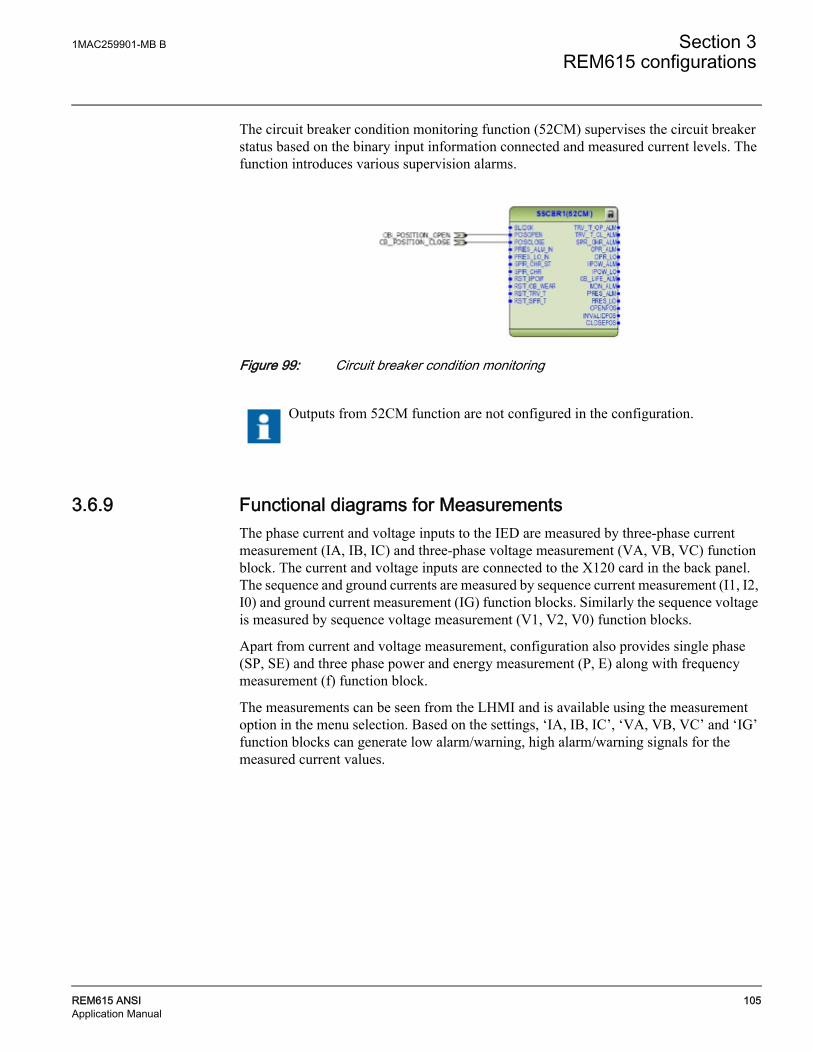
1MAC259901-MB B Section 3REM615 configurations
REM615 ANSI 105Application Manual
The circuit breaker condition monitoring function (52CM) supervises the circuit breaker status based on the binary input information connected and measured current levels. The function introduces various supervision alarms.
Figure 99: Circuit breaker condition monitoring
3.6.9 Functional diagrams for MeasurementsThe phase current and voltage inputs to the IED are measured by three-phase current measurement (IA, IB, IC) and three-phase voltage measurement (VA, VB, VC) function block. The current and voltage inputs are connected to the X120 card in the back panel. The sequence and ground currents are measured by sequence current measurement (I1, I2, I0) and ground current measurement (IG) function blocks. Similarly the sequence voltage is measured by sequence voltage measurement (V1, V2, V0) function blocks.
Apart from current and voltage measurement, configuration also provides single phase (SP, SE) and three phase power and energy measurement (P, E) along with frequency measurement (f) function block.
The measurements can be seen from the LHMI and is available using the measurement option in the menu selection. Based on the settings, ‘IA, IB, IC’, ‘VA, VB, VC’ and ‘IG’ function blocks can generate low alarm/warning, high alarm/warning signals for the measured current values.
Outputs from 52CM function are not configured in the configuration.

Section 3 1MAC259901-MB B
REM615 configurations
106 REM615 ANSIApplication Manual
Figure 100: Measurements
3.6.10 Functional diagrams for other functions Configuration also includes other miscellaneous basic functions which are not configured, but can be used for creating general purpose logics. These functions include:
• Four instance of Minimum Pulse Timer TP-1, TP-2, TP-3 and TP-4,
• Two instance of Pulse Timer PT-1 and PT-2,
• Two instance of Time delay off TOF-1 and TOF-2,
• Two instance of Time delay on TON-1 and TON-2,
• Two instance of Set reset logic SR-1 and SR-2, and
• Two instance of Move logic MV-1 and MV-2
3.6.11 Functional diagrams for logging functions The disturbance recorder DFR consists of 64 channels. However, as default, very few channels are connected to trigger the digital fault recorder are as shown in Figure 24. More connections can be made as per individual need. Also when disturbance recorder is trigger the analog values available at the analog inputs are recorded by fault recorder FR.

1MAC259901-MB B Section 3REM615 configurations
REM615 ANSI 107Application Manual
Figure 101: 64 channel Disturbance and fault recorder
3.6.12 Functional diagrams for I/O and Alarm LEDs The default binary I/O connected in the configuration and Alarm LEDs are indicated in to

Section 3 1MAC259901-MB B
REM615 configurations
108 REM615 ANSIApplication Manual
Figure 102: Binary inputs
Figure 103: Binary outputs

1MAC259901-MB B Section 3REM615 configurations
REM615 ANSI 109Application Manual
Figure 104: Alarm LEDs
High speed binary outputs (HSO) are available only if IED with High speed binary card has been ordered.

Section 3 1MAC259901-MB B
REM615 configurations
110 REM615 ANSIApplication Manual


Contact us
ABB Inc.Distribution Automation4300 Coral Ridge DriveCoral Springs, FL 33065, USAPhone:+1 (800) 523-2620Phone:+1 954-752-6700Fax:+1 954 345-5329www.abb.com/substationautomation
1MA
C25
990
1-M
B B
© C
opyr
igh
t 201
1 A
BB
. All
right
s re
serv
ed.