remanufacture of turbine blades by laser cladding...
TRANSCRIPT
Remanufacture of turbine blades by laser cladding, machining and in-process scanning in a single machine
Jason Jones1, Phil McNutt2, Riccardo Tosi3, Clinton Perry4 and David Wimpenny1,3
1 Department of Engineering, De Montfort University, Leicester, Leicestershire, UK
2 The Welding Institute (TWI), Cambridge, UK 3 Manufacturing Training Centre, Coventry, UK
4 Delcam plc, Birmingham, UK
ARTICLE INFO ABSTRACT
Keywords:
Remanufacturing Laser cladding Inspection Additive Manufacturing (AM) Adaptive machining Hybrid processing Repair
Remanufacturing is one of the most efficient ways of recycling worn parts because it consumes only a fraction of the energy, cost, and material required for new parts. Remanufacture of engineering components typically entails serial labor intensive and operator skill sensitive processes, often requiring parts to move between manufacturers and subcontractors. Unfortunately the logistics and quality assurance measures required for effective remanufacturing currently restrict its implementation primarily to high value components (e.g. turbine blades, blisks, etc.). This research reports progress toward an integrated production system which combines laser cladding, machining and in-process scanning in a single machine for flexible and lean remanufacturing.
1 Introduction Remanufacturing has been called the “ultimate form”
of recycling worn parts because it consumes only a fraction of the energy, cost, and material required for new parts [1-3]. Remanufacture of engineering components typically entails serial labor intensive and operator skill sensitive processes, often requiring parts to move between manufacturers and subcontractors and has been discussed elsewhere [4]. Unfortunately the logistics and quality assurance measures required for effective remanufacturing currently restrict its implementation to high value components (e.g. turbine blades, blisks, etc.) [4, 5].
Efforts to automate steps in the repair process have capitalized on the use of high-speed metal removal (by machining/grinding), scanning/inspection techniques and laser cladding/welding (aka direct energy deposition ASTM F2792) [6]. Although these processes are well established individually, no solution integrating all three is commercially available. Generally, most blade repair methodologies (See Table 1) still rely on manual initial and final inspection, weld preparation grinding, welding, and blend grinding with increasing use of CNC machining sometimes with semi- or automated inspection [7, 8]. State of the art consists of co-locating these processes in the same manufacturing cell [9, 10], or in some cases integrating them into the same machine in pairs (milling + inspection; laser cladding + inspection, e.g. Huffman Corp, TRUMPF Laser GmbH, etc. [4]; milling + laser
cladding, [11-13]). Although the introduction of automation has advanced repair productivity, quality, and reduced costly re-work on a stepwise basis, the absence of a fully integrated repair solution still represents a significant opportunity for reducing adoption risk and barriers such as capital investment, floor space, work flow/data flow management and integration of at least two or more machines. Moreover, a fully integrated approach could eliminate the need to set up each work piece on each machine at each processing stage which can be labor intensive, lead to errors in part set up, and generate significant levels of work in progress [9].
Since late 2008 a UK based consortium has been developing a solution fully integrating processes and software for automated repair applications and has dubbed its approach: RECLAIM (REmanufacture of high value products using a Combined LAser cladding, Inspection and Machining system). This approach is built on the hypothesis that shifting from work piece flow production to tool flow production enables repair that is not currently feasible. The core innovation focus has been the re-development of laser cladding hardware to enable machine-tool changeability and the development of adaptive software to compensate for part-to-part variation inherent in components due for remanufacture (which have different service histories, wear, damage, etc.).
This paper explains the RECLAIM approach and development work leading to the fully integrated solution. The re-tipping of aerospace turbine blades was initially
821

investigated. More recently, the full integration of laser cladding, inspection and milling has enabled evaluation of the cost-effectiveness of remanufacturing lower value components (turbo charger parts). In addition to repairing damaged parts, embryonic trials were undertaken to establish the feasibility of manufacturing totally new complex metal parts, upgrading obsolete parts and reconfiguring standard parts for low volume applications.
2 Repair of aerospace turbine blades
Typical turbine blade wear and corresponding reconditioning steps have been discussed elsewhere [4, 7, 8, 14] and vary from manufacturer to manufacturer and even from job to job depending on the component defects, material composition, service conditions and quality assurance practices. For the purpose of this research a typical blade repair process for titanium alloy blades with tip deformation and wear (for example, Figure 1) is shown in Table 1. The scope of our initial trials focused on tip repair since it routinely wears most and accounts for the vast majority of remanufacturing activity (compared to edge repair or cropping).
Table 1 – Conventional Airfoil remanufacture steps*
1. Initial inspection (visual) 2. Weld preparation (manual grinding) 3. Tip welding (manual weld deposition)
4. Tip finishing (manual grinding or CNC milling)
5. Blending (manual grinding & polishing) 6. Inspection (visual, hardness, crack penetrant test, X-ray,
etc.) Bold = steps targeted for automation and integration in this research * Additional process steps may be required including cleaning (by acid dipping), balancing, and heat treatment.
Figure 1 – Typical deformation on the tips of a compressor blade
Each of the manual steps in bold in Table 1 was targeted to be superseded with automation in order to improve efficiency and the consistency of the outcome. Analyzing the current remanufacturing process shaped the research focus by revealing that costly rework is most often associated with defects introduced in connection
with the welding step (3), although chipping and blending (5) errors are also significant. Notably, few instances of re-work were required for CNC milling (4) which is evidence of the potential benefits of automation and justifies integrating it with additional process steps.
3 The RECLAIM approach
The overarching aim of the RECLAIM approach was to deliver a highly agile and adaptive platform where inspection, additive and subtractive capabilities could be deployed without compromise and all be controlled through one integrated software solution. This ethos, which maximizes flexibility, was derived from the extreme variation in volumes, product mix, and product condition encountered in remanufacturing environments.
The approach steps include component alignment, defect characterization, defect removal, defect repair, and finishing all underpinned by adaptive processing as informed by inspection. Automation of the individual approach steps, in the context of aerospace blade re-tipping, was evaluated individually, and then in pairs before integration into one machine as reported below.
3.1 Alignment by probing Theoretically, repair of compressor blade tip wear
could be done from a single work piece fixture setup which would necessitate automated alignment only once before processing; however the first step taken was to develop alignment routines for the integration of steps 4-5. For that, compressor blades (with welded tips) were mounted one at a time into a fixture (Figure 2) in a 5 axis CNC machine (development trials were undertaken on a VMC3020, Fadal, CA, USA and 5AX VMC, Hardinge, NY, USA with Siemens 840D control) and a scanning probe (SPRINT™, Renishaw plc, UK) used a raster search routine to find the leading and trailing edges of the blade for establishing its initial location and orientation in the fixture relative to the machine coordinate system. The probing process was managed by 5-axis on-machine inspection software (PowerINSPECT, Delcam plc, UK).
Figure 2 – Adaptively probing a compressor blade
~5 mm
822

3.2 Defect characterization by scanning Once the initial alignment was established, the blade
(damaged or tip welded) was continuously scanned (using the same probe as above) at 300 mm/min capturing 1000 points/sec. on its edges and surfaces (both pressure and suction) to characterize its exact shape and size including areas of damage/deformation. Current scanning accuracy with error mapping is sub-10 microns. This data was used to represent the unrepaired (or recently welded) blade tip in three-dimensional CAD (Figure 3) for comparison with the nominal CAD model and customization of tool paths for downstream operations as described below. This protocol for characterizing worn blades returned a more consistent damage/wear profile than expected.
Figure 3 – CAD model of worn blade generated from scan data
3.3 Adaptive tool path generation The machine motion throughout all automated steps
of the RECLAIM approach was managed by gelling together functionality from a software suite which included reverse engineering, fixturing, inspection, CAD, and CAM applications (Delcam Automation software gelled together functionality from PowerSHAPE, Fixture, PowerINSPECT, PowerSHAPE [again], and PowerMILL respectively, all of Delcam plc, UK).
For the blade re-tipping application the scanned points were captured by PowerINSPECT (using Fixture to avoid any collisions) and then translated via PowerSHAPE into a virtual model of the actual 3D geometry. The nominal CAD model was then morphed by PowerSHAPE based on the actual geometry measurements to provide a pseudo-real-time virtual representation of the part as it progressed through the reconditioning steps from which adaptive tool paths were generated by PowerMILL for defect removal, cladding, milling and blending operations.
In this case the adaptive capability was critical, not only to compensate for variability in the defects detected, but also for the variability in blade placement allowed by the non-optimized fixture. Although new components
may be realized without adaptive processing, it was (and is) absolutely essential for successful remanufacturing.
3.4 Defect removal by milling/grinding The RECLAIM system is inherently capable of defect
removal by milling. The original intention was to find defects and adaptively remove them along with the least amount of adjacent material on a blade-by-blade basis, thereby maximizing the speed of downstream process steps. In this case, the lots of damaged airfoil blades used for this research did not warrant adaptive characterization or removal of the defects because the damage was consistent in location and severity (possibly due to thorough initial inspection practices). Additionally, it was determined experimentally that defect removal by milling was less cost-effective than by conventional grinding.
Although this capability was not utilized in this application, it may be useful for other applications with different geometries, sizes and/or materials. Additionally, it is worthwhile remembering that the blades repaired in this research were tagged for research after initial visual inspection which rejects a substantial number of blades not considered suitable for reconditioning. Based on these initial findings, if this approach were adopted for blade repair it could potentially be utilized to reclaim a larger proportion of blades than current practice by expanding the window of defects that can be consistently repaired.
3.5 Defect repair by laser cladding Early cladding trials were undertaken on a laser
welding robot (fiber laser mounted on a Kuka Robot, Kuka Robot Group, Germany) and also on a commercial laser cladding system (HC-205 Laser System, Huffman Corporation, SC, USA) using a 200 Watt CO2 laser at 200-400 mm/min using commercial cladding software (AutoCLAD, Huffman Corporation, SC, USA).
The deposition parameters and strategy were determined experimentally as informed by 3D microscope analysis in order to eliminate weld porosity, achieve a sound bond to the base metal and promote a favorable microstructure. These parameters provided a baseline for cladding using a new developmental cladding head design.
Figure 4 – Laser cladding restoration of material to the tip of a blade with a 50mm chord length
823
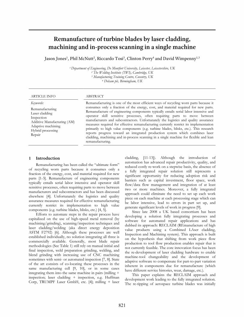
3.6 Tip finish and blend machining The tip was adaptively CNC finish machined and
blended using tool paths derived from PowerMILL (Figure 5). Machining thin wall geometry in titanium without coolant or robust fixturing, using a ball nose cutter necessitated a very conservative 500-1500 mm/min feed speed with a spindle speed of 2000 RPM which is not yet optimized. The milling revealed any short fills from the laser cladding (where not enough material was deposited), but otherwise served to resurface and restore the blade to intended feature shape and tolerance.
Figure 5 – Adaptive CNC blending of repaired airfoil tip
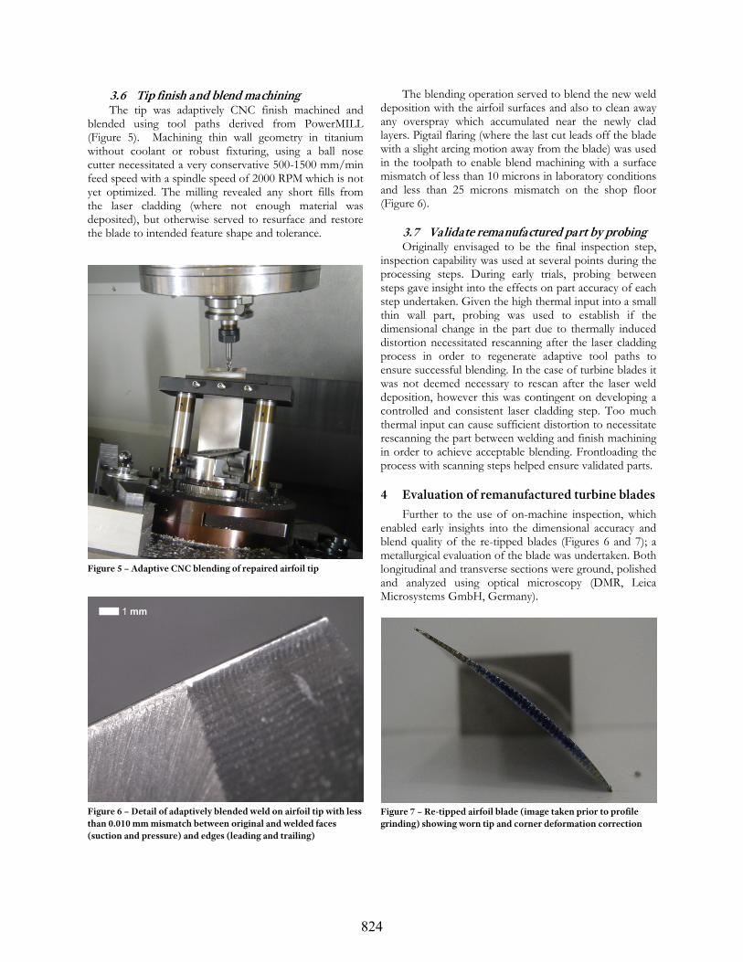
Figure 6 – Detail of adaptively blended weld on airfoil tip with less than 0.010 mm mismatch between original and welded faces (suction and pressure) and edges (leading and trailing)
The blending operation served to blend the new weld deposition with the airfoil surfaces and also to clean away any overspray which accumulated near the newly clad layers. Pigtail flaring (where the last cut leads off the blade with a slight arcing motion away from the blade) was used in the toolpath to enable blend machining with a surface mismatch of less than 10 microns in laboratory conditions and less than 25 microns mismatch on the shop floor (Figure 6).
3.7 Validate remanufactured part by probing Originally envisaged to be the final inspection step,
inspection capability was used at several points during the processing steps. During early trials, probing between steps gave insight into the effects on part accuracy of each step undertaken. Given the high thermal input into a small thin wall part, probing was used to establish if the dimensional change in the part due to thermally induced distortion necessitated rescanning after the laser cladding process in order to regenerate adaptive tool paths to ensure successful blending. In the case of turbine blades it was not deemed necessary to rescan after the laser weld deposition, however this was contingent on developing a controlled and consistent laser cladding step. Too much thermal input can cause sufficient distortion to necessitate rescanning the part between welding and finish machining in order to achieve acceptable blending. Frontloading the process with scanning steps helped ensure validated parts.
4 Evaluation of remanufactured turbine blades
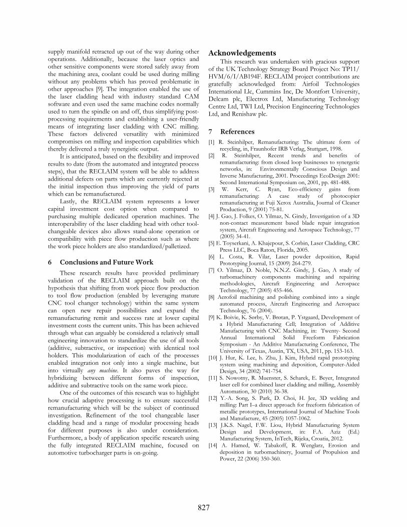
Further to the use of on-machine inspection, which enabled early insights into the dimensional accuracy and blend quality of the re-tipped blades (Figures 6 and 7); a metallurgical evaluation of the blade was undertaken. Both longitudinal and transverse sections were ground, polished and analyzed using optical microscopy (DMR, Leica Microsystems GmbH, Germany).
Figure 7 – Re-tipped airfoil blade (image taken prior to profile grinding) showing worn tip and corner deformation correction
1 mm
824

Figure 8 – Transverse section analysis of laser clad blade tip
Figures 8 and 9 show several areas and magnifications of transverse and longitudinal sections respectively through a typical laser clad blade tip with good fusion to the base material, little weld porosity and no significant abnormalities in the microstructure. This preliminary analysis work was not optimized further because it was primarily intended to serve as a point of reference for new laser cladding head development and its influence on processing parameters and microstructure.
Figure 9 – Longitudinal section analysis of laser clad blade tip
5 Toward the integrated RECLAIM machine The foregoing results supported the rationale and
also provided foundational understanding for the development of a fully integrated system.
In parallel to the research activities on individual (and pairs of) process steps reported above, a tool changeable laser cladding head was designed, manufactured and tested. This new head was a coaxial variant with the
825

powder-beam interface close to the exit of the nozzle (rather than on the surface of the material). This design proved an effective means of reducing thermal input into the substrate and accurately depositing material onto the relatively thin cross-section of the turbine blades with minimal overspray. The new head was designed to be coupled with a detachable manifold to supply it with the required services/media (shielding gas, coolant, powder feed). The manifold can be decoupled automatically to enable the cladding head to be stored in the tool changer (Figure 11). Substantial hardware and software integration enabled the head to be changed automatically using conventional tool change protocol.
Figure 10 – The fully integrated RECLAIM machine with turbocharger impeller re-tipped by it in the foreground
Figure 11 – Tool change from laser cladding head to cutting tool
The new laser cladding head enabled a fully integrated RECLAIM machine incorporating additive, subtractive and inspection capabilities to be assembled (Figure 10). The system was built on a refurbished 4-axis CNC machine (BD18 Vector Machine, Bostomatic1, MA, USA) with OpenCNC control (MDSI, Michigan, USA) running on a Windows XP computer with AC servo drives and
1 Note: Bostomatic is now owned by Agie Charmilles Holding AG, Switzerland.
motors (Yaskawa Electric Corporation, Japan) and a closed loop vector spindle (Bostomatic, MA, USA) configured for standard ISO 40 tapered tool holders. The system featured conventional cutting tools, an optical transmission touch probe (OMP 60, Renishaw plc, UK with wireless receiver mounted inside the machine enclosure) and the new laser cladding head all mounted on standard tool holders and held in the factory standard tool changer (Figure 11).
5.1 Benefits of the RECLAIM system This research adds momentum to and derives benefit
from the hybrid additive and subtractive ethos as utilized in research and in commercial systems including solid-state AM (Fabrisonic LLC, Ohio, USA) and the imminent commercial launch of a powder bed fusion + high-speed milling machine (LUMEX Avance-25, Matsuura, Japan).
The logistics and alignment challenges caused by transporting the test blades between different institutions and moving them between different processing systems during the early investigations reported herein highlight the potential savings and synergies possible with an integral machine. By incorporating all of the process steps into a tool changeable format, the RECLAIM machine becomes a highly agile machine which can digitally adapt to low volume high variability production. The savings potential includes the elimination of part transportation, part movement between machines, repeat setup/ alignment operations, and work in process stock between process steps.
The flexibility of the system also enabled a practical way to invoke additional inspection routines in order to monitor distortion before and after each process step (where necessary) for full characterization (such as to detect and characterize any distortion due to thermal input into thin wall features) or for one off adaptive repair or fabrication work. Without the agility and extensive software integration of the RECLAIM system, this pseudo-real time monitoring of the various processes and their interactions would not be practical.
The parallel research activities reported herein have been realized on several different CNC machine tool makes and architectures. In this way, the compatibility of the RECLAIM approach and hardware with virtually any CNC machine has been vetted. Furthermore, the outcome from individual process steps has been improved due to the high accuracy and rigidity of CNC machine technology. Compared to the early welding trials by manual or even robot deposition, the weld quality improved when made using the far more rigid spindle mounted laser cladding head on the CNC machine. Also, the ability to laser clad on the centerline of the spindle eliminated any need to manage offsets required for off-center deposition. In contrast to off-center cladding configurations, the encroachment on the working area of the machine tool was negligible because the laser cladding head was stored out of the way in the tool changer and the
826
supply manifold retracted up out of the way during other operations. Additionally, because the laser optics and other sensitive components were stored safely away from the machining area, coolant could be used during milling without any problems which has proved problematic in other approaches [9]. The integration enabled the use of the laser cladding head with industry standard CAM software and even used the same machine codes normally used to turn the spindle on and off, thus simplifying post-processing requirements and establishing a user-friendly means of integrating laser cladding with CNC milling. These factors delivered versatility with minimized compromises on milling and inspection capabilities which thereby delivered a truly synergistic output.
It is anticipated, based on the flexibility and improved results to date (from the automated and integrated process steps), that the RECLAIM system will be able to address additional defects on parts which are currently rejected at the initial inspection thus improving the yield of parts which can be remanufactured.
Lastly, the RECLAIM system represents a lower capital investment cost option when compared to purchasing multiple dedicated operation machines. The interoperability of the laser cladding head with other tool-changeable devices also allows stand-alone operation or compatibility with piece flow production such as where the work piece holders are also standardized/palletized.
6 Conclusions and Future Work
These research results have provided preliminary validation of the RECLAIM approach built on the hypothesis that shifting from work piece flow production to tool flow production (enabled by leveraging mature CNC tool changer technology) within the same system can open new repair possibilities and expand the remanufacturing remit and success rate at lower capital investment costs the current units. This has been achieved through what can arguably be considered a relatively small engineering innovation to standardize the use of all tools (additive, subtractive, or inspection) with identical tool holders. This modularization of each of the processes enabled integration not only into a single machine, but into virtually any machine. It also paves the way for hybridizing between different forms of inspection, additive and subtractive tools on the same work piece.
One of the outcomes of this research was to highlight how crucial adaptive processing is to ensure successful remanufacturing which will be the subject of continued investigation. Refinement of the tool changeable laser cladding head and a range of modular processing heads for different purposes is also under consideration. Furthermore, a body of application specific research using the fully integrated RECLAIM machine, focused on automotive turbocharger parts is on-going.
Acknowledgements This research was undertaken with gracious support
of the UK Technology Strategy Board Project No: TP11/ HVM/6/I/AB194F. RECLAIM project contributions are gratefully acknowledged from: Airfoil Technologies International Llc, Cummins Inc, De Montfort University, Delcam plc, Electrox Ltd, Manufacturing Technology Centre Ltd, TWI Ltd, Precision Engineering Technologies Ltd, and Renishaw plc. 7 References [1] R. Steinhilper, Remanufacturing: The ultimate form of
recycling, in, Fraunhofer IRB Verlag, Stuttgart, 1998. [2] R. Steinhilper, Recent trends and benefits of
remanufacturing: from closed loop businesses to synergetic networks, in: Environmentally Conscious Design and Inverse Manufacturing, 2001. Proceedings EcoDesign 2001: Second International Symposium on, 2001, pp. 481-488.
[3] W. Kerr, C. Ryan, Eco-efficiency gains from remanufacturing: A case study of photocopier remanufacturing at Fuji Xerox Australia, Journal of Cleaner Production, 9 (2001) 75-81.
[4] J. Gao, J. Folkes, O. Yilmaz, N. Gindy, Investigation of a 3D non-contact measurement based blade repair integration system, Aircraft Engineering and Aerospace Technology, 77 (2005) 34-41.
[5] E. Toyserkani, A. Khajepour, S. Corbin, Laser Cladding, CRC Press LLC, Boca Raton, Florida, 2005.
[6] L. Costa, R. Vilar, Laser powder deposition, Rapid Prototyping Journal, 15 (2009) 264-279.
[7] O. Yilmaz, D. Noble, N.N.Z. Gindy, J. Gao, A study of turbomachinery components machining and repairing methodologies, Aircraft Engineering and Aerospace Technology, 77 (2005) 455-466.
[8] Aerofoil machining and polishing combined into a single automated process, Aircraft Engineering and Aerospace Technology, 76 (2004).
[9] K. Boivie, K. Sørby, V. Brøtan, P. Ystgaard, Development of a Hybrid Manufacturing Cell; Integration of Additive Manufacturing with CNC Machining, in: Twenty- Second Annual International Solid Freeform Fabrication Symposium - An Additive Manufacturing Conference, The University of Texas, Austin, TX, USA, 2011, pp. 153-163.
[10] J. Hur, K. Lee, h. Zhu, J. Kim, Hybrid rapid prototyping system using machining and deposition, Computer-Aided Design, 34 (2002) 741-754.
[11] S. Nowotny, R. Muenster, S. Scharek, E. Beyer, Integrated laser cell for combined laser cladding and milling, Assembly Automation, 30 (2010) 36-38.
[12] Y.-A. Song, S. Park, D. Choi, H. Jee, 3D welding and milling: Part I–a direct approach for freeform fabrication of metallic prototypes, International Journal of Machine Tools and Manufacture, 45 (2005) 1057-1062.
[13] J.K.S. Nagel, F.W. Liou, Hybrid Manufacturing System Design and Development, in: F.A. Aziz (Ed.) Manufacturing System, InTech, Rijeka, Croatia, 2012.
[14] A. Hamed, W. Tabakoff, R. Wenglarz, Erosion and deposition in turbomachinery, Journal of Propulsion and Power, 22 (2006) 350-360.
827