remeha p · pdf file5 06/04/06 - 300008452-001-c remeha p 320 1 technical characteristics...
TRANSCRIPT

Remeha P 320Fuel oil/gas boilers
Technical instructions
English06/04/06
63184
UK

Contents
Introduction . . . . . . . . . . . . . . . . . . . . . . . . . . . . . . . . . . . . . . . . . . . . . . . . . . . . . . . . . . . . . . . . . . . . . . . . . . . . . . . . .3
Description . . . . . . . . . . . . . . . . . . . . . . . . . . . . . . . . . . . . . . . . . . . . . . . . . . . . . . . . . . . . . . . . . . . . . . . . . . . . . . . . . .41 Technical characteristics . . . . . . . . . . . . . . . . . . . . . . . . . . . . . . . . . . . . . . . . . . . . . . . . . . . . . . . . . . . . . . . . . . . . . . . . . . . . . . . . . . . .52 Main dimensions . . . . . . . . . . . . . . . . . . . . . . . . . . . . . . . . . . . . . . . . . . . . . . . . . . . . . . . . . . . . . . . . . . . . . . . . . . . . . . . . . . . . . . . . . .6
Installing the boiler . . . . . . . . . . . . . . . . . . . . . . . . . . . . . . . . . . . . . . . . . . . . . . . . . . . . . . . . . . . . . . . . . . . . . . . . . . .71 Boiler location. . . . . . . . . . . . . . . . . . . . . . . . . . . . . . . . . . . . . . . . . . . . . . . . . . . . . . . . . . . . . . . . . . . . . . . . . . . . . . . . . . . . . . . . . . . . .72 Ventilation. . . . . . . . . . . . . . . . . . . . . . . . . . . . . . . . . . . . . . . . . . . . . . . . . . . . . . . . . . . . . . . . . . . . . . . . . . . . . . . . . . . . . . . . . . . . . . . .8
Mounting. . . . . . . . . . . . . . . . . . . . . . . . . . . . . . . . . . . . . . . . . . . . . . . . . . . . . . . . . . . . . . . . . . . . . . . . . . . . . . . . . . . .8
Hydraulic connections . . . . . . . . . . . . . . . . . . . . . . . . . . . . . . . . . . . . . . . . . . . . . . . . . . . . . . . . . . . . . . . . . . . . . . . .91 Important recommendations on connecting the heating circuit to the boiler and the drinking water system . . . . . . . . . . . . . . . . . . . . .92 Important recommendations for connecting the boiler to the heating circuit . . . . . . . . . . . . . . . . . . . . . . . . . . . . . . . . . . . . . . . . . . . .103 Filling the system . . . . . . . . . . . . . . . . . . . . . . . . . . . . . . . . . . . . . . . . . . . . . . . . . . . . . . . . . . . . . . . . . . . . . . . . . . . . . . . . . . . . . . . . .114 Sludge removal . . . . . . . . . . . . . . . . . . . . . . . . . . . . . . . . . . . . . . . . . . . . . . . . . . . . . . . . . . . . . . . . . . . . . . . . . . . . . . . . . . . . . . . . . .11
Chimney connection . . . . . . . . . . . . . . . . . . . . . . . . . . . . . . . . . . . . . . . . . . . . . . . . . . . . . . . . . . . . . . . . . . . . . . . . .121 Flue size . . . . . . . . . . . . . . . . . . . . . . . . . . . . . . . . . . . . . . . . . . . . . . . . . . . . . . . . . . . . . . . . . . . . . . . . . . . . . . . . . . . . . . . . . . . . . . . .122 Chimney connection. . . . . . . . . . . . . . . . . . . . . . . . . . . . . . . . . . . . . . . . . . . . . . . . . . . . . . . . . . . . . . . . . . . . . . . . . . . . . . . . . . . . . . .12
Fuel-oil or gas connections . . . . . . . . . . . . . . . . . . . . . . . . . . . . . . . . . . . . . . . . . . . . . . . . . . . . . . . . . . . . . . . . . . .13
Electrical connections. . . . . . . . . . . . . . . . . . . . . . . . . . . . . . . . . . . . . . . . . . . . . . . . . . . . . . . . . . . . . . . . . . . . . . . .13
Maintenance . . . . . . . . . . . . . . . . . . . . . . . . . . . . . . . . . . . . . . . . . . . . . . . . . . . . . . . . . . . . . . . . . . . . . . . . . . . . . . . .141 Sweeping . . . . . . . . . . . . . . . . . . . . . . . . . . . . . . . . . . . . . . . . . . . . . . . . . . . . . . . . . . . . . . . . . . . . . . . . . . . . . . . . . . . . . . . . . . . . . . .142 Cleaning the casing material . . . . . . . . . . . . . . . . . . . . . . . . . . . . . . . . . . . . . . . . . . . . . . . . . . . . . . . . . . . . . . . . . . . . . . . . . . . . . . . .153 Precautions required in the case of long boiler stops (one or more years) . . . . . . . . . . . . . . . . . . . . . . . . . . . . . . . . . . . . . . . . . . . . .154 Precautions required if the heating is stopped when there is a risk of freezing . . . . . . . . . . . . . . . . . . . . . . . . . . . . . . . . . . . . . . . . . .15
Burner maintenance . . . . . . . . . . . . . . . . . . . . . . . . . . . . . . . . . . . . . . . . . . . . . . . . . . . . . . . . . . . . . . . . . . . . . . . . .16
System maintenance . . . . . . . . . . . . . . . . . . . . . . . . . . . . . . . . . . . . . . . . . . . . . . . . . . . . . . . . . . . . . . . . . . . . . . . . .161 Water level . . . . . . . . . . . . . . . . . . . . . . . . . . . . . . . . . . . . . . . . . . . . . . . . . . . . . . . . . . . . . . . . . . . . . . . . . . . . . . . . . . . . . . . . . . . . . .162 Draining . . . . . . . . . . . . . . . . . . . . . . . . . . . . . . . . . . . . . . . . . . . . . . . . . . . . . . . . . . . . . . . . . . . . . . . . . . . . . . . . . . . . . . . . . . . . . . . .16
Identification plate . . . . . . . . . . . . . . . . . . . . . . . . . . . . . . . . . . . . . . . . . . . . . . . . . . . . . . . . . . . . . . . . . . . . . . . . . . .16
Spare parts - P 320. . . . . . . . . . . . . . . . . . . . . . . . . . . . . . . . . . . . . . . . . . . . . . . . . . . . . . . . . . . . . . . . . . . . . . . . . . .17
Remeha P 320 06/04/06 - 300008452-001-C

Introduction
Directive 97/23/ECGas and oil boilers with a maximum operating temperature of 110°Cand hot water tanks with a maximum operating pressure of 10 barpertain to article 3.3 of the directive, and therefore, cannot be CE-marked to certify compliance with the directive 97/23 EC.The boilers and hot water tanks are designed and manufactured inaccordance with the sound engineering practice, as requested inarticle 3.3 of the directive 97/23/EC; it is certified by compliance withthe directives 90/396/EC, 92/42/EC, 73/23 EC and 89/336/EC.
Warning
The boiler shall be assembled and installed by a qualifiedprofessional only.For a proper operating of the boiler, follow carefully the instructions.
Symbols used
Caution danger Risk of injury and damage to equipment. Attention must be paid to the warnings on safety of persons and equipment
Specific information Information must be kept in mind to maintain comfort
Reference Refer to another manual or other pages in this instruction manual
306/04/06 - 300008452-001-C Remeha P 320

Description
The boilers of the P 320 range are pressurised hot water boilersdesigned for connecting to a flue pipe which require a separateautomatic fuel-oil or gas burner.The useful power of P 320 boilers is between 70 and 330 kW.Models availableBoiler with control panel, which may be fitted with an optionalRematic 2945 C3K control unit for heating only or heating anddomestic hot water production.
4 Remeha P 320 06/04/06 - 300008452-001-C
1 Technical characteristics
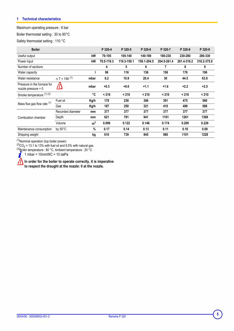
Maximum operating pressure : 6 barBoiler thermostat setting : 30 to 90°CSafety thermostat setting : 110 °C
(1)Nominal operation (top boiler power)(2)CO2 = 13.1 to 13% with fuel oil and 9.5% with natural gas.(3)Boiler temperature : 80 °C, Ambient temperature : 20 °C
1 mbar = 10mmWC = 10 daPa
In order for the boiler to operate correctly, it is imperativeto respect the draught at the nozzle: 0 at the nozzle.
Boiler P 320-4 P 320-5 P 320-6 P 320-7 P 320-8 P 320-9
Useful output kW 70-105 105-140 140-180 180-230 230-280 280-330Power input kW 79.5-119.3 119.3-159.1 159.1-204.5 204.5-261.4 261.4-318.2 318.2-375.0Number of sections 4 5 6 7 8 9Water capacity l 96 116 136 156 176 196Water resistance ∆ T = 15K (1) mbar 6.2 10.9 20.4 30 44.5 63.8Pressure in the furnace for nozzle pressure = 0 mbar +0.3 +0.6 +1.1 +1.6 +2.2 +2.5
Smoke temperature (1) (3) °C < 210 < 210 < 210 < 210 < 210 < 210
Mass flue gas flow rate (1) Fuel oil Kg/h 178 238 306 391 475 560Gas Kg/h 187 250 321 410 499 588
Combustion chamberRecorded diameter mm 377 377 377 377 377 377Depth mm 621 781 941 1101 1261 1369Volume m3 0.096 0.122 0.148 0.174 0.200 0.226
Maintenance consumption by 50°C % 0.17 0.14 0.13 0.11 0.10 0.09Shipping weight kg 610 739 845 980 1101 1228
506/04/06 - 300008452-001-C Remeha P 320
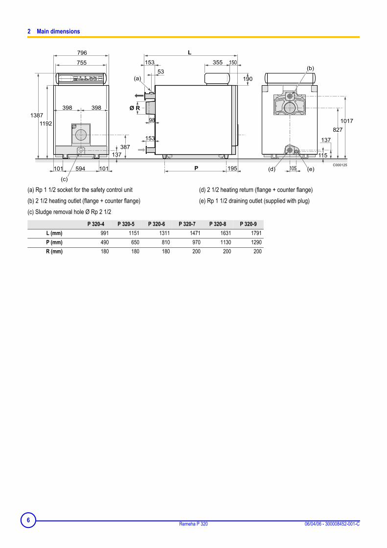
2 Main dimensions
(a) Rp 1 1/2 socket for the safety control unit(b) 2 1/2 heating outlet (flange + counter flange)(c) Sludge removal hole Ø Rp 2 1/2
(d) 2 1/2 heating return (flange + counter flange)(e) Rp 1 1/2 draining outlet (supplied with plug)
P 320-4 P 320-5 P 320-6 P 320-7 P 320-8 P 320-9L (mm) 991 1151 1311 1471 1631 1791P (mm) 490 650 810 970 1130 1290R (mm) 180 180 180 200 200 200
6 Remeha P 320 06/04/06 - 300008452-001-C

Installing the boiler
1 Boiler location
The P320 boiler does not require a special base for its assembly.Their closed furnace system means that the floor need not haverefractory properties. All you have to ensure is that the floor cansupport the weight of the boiler when it is fitted for operation. If theboiler location is not determined precisely, leave enough spacearound the boiler to facilitate monitoring and maintenanceoperations.
Pay attention to the overall volume of the burner when thedoor is open. To install several boilers in cascade, thesedimensions should be adapted accordingly.
Boiler P 320-4 P 320-5 P 320-6 P 320-7 P 320-8 P 320-9A 840 1000 1160 1320 1480 1640
706/04/06 - 300008452-001-C Remeha P 320
2 Ventilation
The location of air inlets in relation to the high ventilation openingsshall ensure that the air is renewed in the entire volume of the boilerroom.It is in any case imperative to conform to the local regulations in force.
Warning:
In order to avoid damage to the boilers, it is necessary to prevent thecontamination of combustion air by chlorine and/or fluoridecompounds, which are particularly corrosive.These compounds are present, for example, in aerosol sprays,paints, solvents, cleaning products, washing products, detergents,glues, snow clearing salts, etc.Therefore:• Do not suck in air evacuated from premises using such
products: hairdressing salons, dry cleaners, industrial premises (solvents), premises containing refrigeration systems (risk of refrigerant leakage), etc.
• Do not stock such products close to the boilers.If the boiler and/or peripheral equipment are corroded by suchchloride or fluoride compounds, the contractual guaranteecannot be applied.
Mounting
For mounting instructions, see installation instructions.
8 Remeha P 320 06/04/06 - 300008452-001-C

Hydraulic connections
1 Important recommendations on connecting the heating circuit to the boiler and the drinking water system
Installation must be carried out in accordance with the prevailingregulations, the codes of practice and the recommendations in theseinstructions.The expansion tank must be connected directly to the boiler withoutvalves or stop valves.
Likewise, the safety valve must be connected directly to the boilerwithout valves or stop valves.Example of an installation:The example of an installation shown below does not cover everypossible configuration. Its sole aim is to draw your attention to thebasic rules to be respected. Comply at all times with the codes ofpractice and the prevailing national or local regulations.
P 320 boiler with domestic hot water production using an independent tank
1. Heating outlet2. Heating return3. 3 bar safety valve + manometer5. Flow switch6. Air separator7. Automatic bleed valve9. Isolation valve10. 3-way mixing valve11. Boiler pump12. Sludge decanting pot (particularly recommended on older
installations)13. Flush valve14. Water low safety pressure-sensitive switch15. Recycling pump16. Expansion chamber17. Drain cock18. Heating circuit filling (with disconnector depending on prevailing
regulations)19. Water treatment if TH > 25°20. Water meter26. DHW load pump27. Non-return valve28. Domestic cold water inlet
29. Pressure reducer (if mains pressure 5.5 bar)30. Sealed safety unit calibrated to 7 bar with indicator type discharge31. Independent domestic hot water tanks32. Domestic hot water loop pump (optional)56. Domestic hot water circulation return loop57. Domestic hot water outlet
8219N008C
92
1412
17
11279
56
32
9101
9
579
27
26
15
9
17
189 19 20 9
17
16
13
3
7 9
7
30
289
29
27
931
5 6
99
9
906/04/06 - 300008452-001-C Remeha P 320

2 Important recommendations for connecting the boiler to the heating circuit
Installation must be carried out in accordance with the prevailingregulations, the codes of practice and the recommendations in theseinstructions.
Minimum safety valve flowrate as a function of maximum boiler nominal output :
Minimum relieving capacityMaximum gross boiler output
ExampleMaximum boiler nominal output is 200 kW.Minimum safety valve flowrate must be 1500 Kg/h
Water flow in the boiler :
The water flow in the boiler when the burner is operating must correspond with the following formulae:- Nominal water flow Qn = 0.86 Pn/20- Minimum flow Qmin = 0.86 Pn/45 (this flow also corresponds with the minimum recycle flow in the boiler)- Maximum water flow Qmax = 0.86 Pn/5Qn = flow in m3/hPn = Nominal output (full boiler output) in kW.
Operation in cascade
After stopping the burner:- Timeout required before the order to close a butterfly valve: 3 min- Switch a possible shunt pump (located between the boiler and a butterfly valve) off via the end of run contact of the butterfly valve
Operation with 2-stage burner
- The water temperature in the boiler is maintained at 50°C or more ; the first stage must be set to a minimum of 30% of the nominal stage- Operation at modulated low temperature (minimum outlet temperature: 30°C) ; the first stage must be set to a minimum of 50% of the nominal
stage
10 Remeha P 320 06/04/06 - 300008452-001-C
Operation with modulating burner
- The water temperature in the boiler is maintained at 50°C or more: the burner can modulate down to 30% of the nominal stage- Operation at modulated low temperature (minimum outlet temperature: 30°C) ; the burner can modulate down to 50% of the nominal stage
3 Filling the system
Filling shall be performed with a low flow rate from a low point in theboiler room in order to ensure that all the air in the boiler is bled fromthe high point of the system.Always stop the pump before filling.
VERY IMPORTANT : Instructions for starting up the boilerfor the first time after the system is fully or partly drained :If all the air is not bled naturally to an expansion vesselwhich opens out onto the air, the system must includemanual bleeder valves, in addition to automatic bleedervalves with the capability to bleed the system bythemselves when it is operating; the manual bleeder valvesare used to bleed all the high points of the system and tomake sure that the filled system is free of air before theburner is turned on.
Do not add cold water suddenly into the boiler when it ishot.
4 Sludge removal
A tapped Ø 1’’ 1/2 hole with a plug has been provided on the bottomof the front of the boiler.. Fit a 1/4 turn valve (not supplied) on theopening to remove the sludge.Sludge removal leads to the draining of large quantities of water, soremember to refill the system after the operation.Comments : never replace a boiler in an existing system without carefully rinsingthe system first. Install a sludge decanting pot on the return pipe, veryclose to the boiler.
1106/04/06 - 300008452-001-C Remeha P 320

Chimney connection
The high-performance features of modern boilers and their use inspecific conditions as a result of the advance in burner technology(e.g. first-stage or low modulation range operation) lead to very lowflue gas temperatures (<160°C).
For this reason :- Use flue gas pipes designed to enable the flow of condensates
which may result from such operating modes in order to preventdamage to the chimney.
- Install a draining tee at the bottom of the chimney.
The use of a draught moderator is recommended as well.
1 Flue size
Refer to applicable regulations while determining the size of the flue.Please note that P 320 boilers have pressurised and tight furnacesand that the pressure at the nozzle must not exceed 0 mbar, unlessspecial sealing precautions have been taken, for instance in order toconnect a static condenser/regenerator.
2 Chimney connection
The connection shall be removable, and offer minimum load losses,i.e. it must be as short as possible with no sudden change in section.Its diameter shall always be at least equal to that of the boiler outlet,i.e. :Ø 180 mm : for 4 to 6 sectionsØ 200 mm : for 7 to 9 sectionsFit a measuring point (Ø 10 mm hole) on the flue, in order to adjustthe burner (combustion check).
12 Remeha P 320 06/04/06 - 300008452-001-C

Fuel-oil or gas connections
Refer to the instructions supplied with the burner. The burner head deflector must be flush with the insulationof the burner door.
A : Furnace door insulationB : 4 markings on Ø 170C : 4 markings on Ø 200D : 4 markings on Ø 220
Electrical connections
Refer to the connection instructions supplied with the controlpanel.
1306/04/06 - 300008452-001-C Remeha P 320
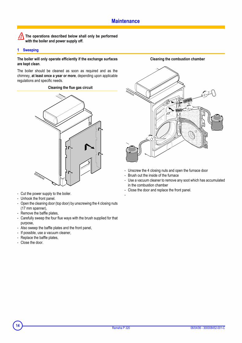
Maintenance
The operations described below shall only be performedwith the boiler and power supply off.
1 Sweeping
The boiler will only operate efficiently if the exchange surfacesare kept clean.The boiler should be cleaned as soon as required and as thechimney, at least once a year or more, depending upon applicableregulations and specific needs.
Cleaning the flue gas circuit
- Cut the power supply to the boiler.- Unhook the front panel.- Open the cleaning door (top door) by unscrewing the 4 closing nuts
(17 mm spanner),- Remove the baffle plates,- Carefully sweep the four flue ways with the brush supplied for that
purpose,- Also sweep the baffle plates and the front panel,- If possible, use a vacuum cleaner,- Replace the baffle plates,- Close the door.
Cleaning the combustion chamber
- Unscrew the 4 closing nuts and open the furnace door- Brush out the inside of the furnace- Use a vacuum cleaner to remove any soot which has accumulated
in the combustion chamber- Close the door and replace the front panel.-
14 Remeha P 320 06/04/06 - 300008452-001-C

Positioning of the baffles
The first two baffles on the two lower flue ways are fittedwith stops to position them in the right place.
(1) Stop
Cleaning the flue gas box
- Remove the left and right cleaning hatches from the flue gas box(2 butterfly nuts) and use a vacuum cleaner to remove any sootwhich has accumulated
- Replace the cleaning hatches.
Maintenance of the burner
Refer to the instructions supplied with the burner
2 Cleaning the casing material
Use a soapy solution and a sponge only. Rinse with clean water anddry with chamois leather or a soft cloth.
3 Precautions required in the case of long boiler stops (one or more years)
- The boiler and the chimney must be swept carefully.- Close all the doors of the boiler to prevent air from circulating inside
the boiler.
- We advise removing the pipe which connects the boiler to thechimney and to close off the nozzle with a cover.
4 Precautions required if the heating is stopped when there is a risk of freezing
We recommend the use of a correctly dosed antifreeze agent toprevent to the heating circuit from freezing. If this cannot be done,drain the system completely.
Baffle plates Flue ways P 320-4 P 320-5 P 320-6 P 320-7 P 320-8 P 320-9
upper410 mm A + B - 8 8 - - -570 mm A + B 4 - - 4 4 4
interior 412 mm C 2 2 2 2 2 2
1506/04/06 - 300008452-001-C Remeha P 320

Burner maintenance
Refer to the instructions supplied with the burner.
System maintenance
1 Water level
Regularly check the level of water in the system and top up ifrequired, taking care that cold water is not added suddenly into theboiler when it is hot.
This operation should be required only a few times in each heatingseason, with very low quantities of water; otherwise, look for the leakand repair it.
2 Draining
We advise you against draining the system unless it is absolutelynecessary.
Identification plate
The identification plate fixed on the side of the boiler duringinstallation is used to identify the boiler correctly and also providesthe main specifications of the boiler.
A : Boiler typeB : Year of manufactureC : Week of manufactureD : Serial no. of the appliance
16 Remeha P 320 06/04/06 - 300008452-001-C

Spare parts - P 320
To order a spare part, quote the reference number next to the part required.
06/04/06 - UK300004553-002-A
Boiler body
1706/04/06 - 300008452-001-C Remeha P 320

Insulation
Base frame
18 Remeha P 320 06/04/06 - 300008452-001-C
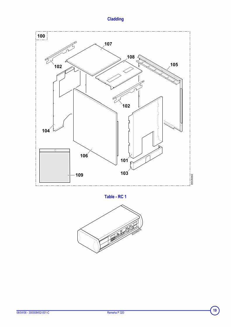
Cladding
Table - RC 1
1906/04/06 - 300008452-001-C Remeha P 320
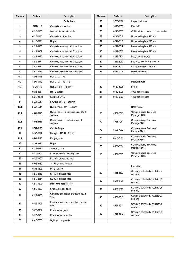
Markers Code no. Description
Boiler body
1 82198912 Complete rear section
2 8219-8966 Special intermediate section
3 8219-8976 Complete front section
4 8116-0571 Nipple
5 8219-8968 Complete assembly rod, 4 sections
5 8219-8969 Complete assembly rod, 5 sections
5 8219-8970 Complete assembly rod, 6 sections
5 8219-8971 Complete assembly rod, 7 sections
5 8219-8972 Complete assembly rod, 8 sections
5 8219-8973 Complete assembly rod, 9 sections
6.1 8202-0028 Plug 2 1/2" - 1/2"
6.2 8209-0049 Plug 2 1/2" - 1/2" - NL
6.3 94948080 Nipple N 241 - 1/2"x1/4"
7 9536-5611 Rp 1/2 pocket
8 80013-0028 Solid plug 2" 1/2
9 8553-5513 Flow flange, 3 to 9 sections
10.1 8553-5514 Return flange, 4 to 5 sections
10.2 8553-5515 Return flange + distribution pipe, 6 to 8 sections
10.3 8553-5516 Return flange + distribution pipe, 9 sections
10.4 9754-9178 Counter flange
11 9495-0249 Male plug 290 T9 - R 1 1/2
11.1 9501-4122 Flange gasket
12 8104-8984 Hinge
13 8219-8916 Sweeping door
14 9425-0306 Inner protection, sweeping door
15 9425-0305 Insulation, sweeping door
16 9508-6032 10 Ø thermocord gasket
17 9756-0203 Pin Ø 12x350
18 8219-8913 Ø 180 complete nozzle
18 8219-8914 Ø 200 complete nozzle
19 8219-0206 Right hand nozzle cover
20 8219-0207 Left hand nozzle cover
21 8219-8953 Complete combustion chamber door, ø 135
22 9425-0303 Internal protection, combustion chamber door
23 9425-0302 Furnace door guard
24 9425-0301 Furnace door insulation
25 8015-7700 Sight glass + gaskets
26 9757-0027 Inspection flange
27 9495-0050 Plug 1/4"
28 8219-0539 Guide rail for combustion chamber door
29 8219-0017 Upper baffle plate, 410 mm
29 8219-0018 Upper baffle plate, 570 mm
30 8219-0019 Lower baffle plate, 412 mm
30 8219-0020 Lower baffle plate, 572 mm
31 8219-7724 Body screws packet
32 8219-8957 Bag of screws for furnace door
33 9430-5027 0.3 kg can nipple lubricant
34 9432-0214 Mastic Novasil S 17
Miscellaneous
50 9750-5025 Brush
51 9750-5076 1000 mm brush rod
51 9750-5060 1300 mm brush rod
Base frame
70 8553-7060 Complete frame 4 sectionsPackage FD 30
70 8553-7061 Complete frame 5 sectionsPackage FD 31
70 8553-7062 Complete frame 6 sectionsPackage FD 32
70 8553-7063 Complete frame 7 sectionsPackage FD 33
70 8553-7064 Complete frame 8 sectionsPackage FD 34
70 8553-7065 Complete frame 9 sectionsPackage FD 35
Insulation
90 8553-5507 Complete boiler body insulation, 4 sections
90 8553-5008 Complete boiler body insulation, 5 sections
90 8553-5509 Complete boiler body insulation, 6 sections
90 8553-5510 Complete boiler body insulation, 7 sections
90 8553-5511 Complete boiler body insulation, 8 sections
90 8953-5512 Complete boiler body insulation, 9 sections
Markers Code no. Description

Cladding
100 100003501 Complete cladding, 4 sections
100 100003502 Complete cladding, 5
100 100003503 Complete cladding, 6
100 100003504 Complete cladding, 7
100 100003505 Complete cladding, 8
100 100003506 Complete cladding, 9
101 200003545 Front panel
102 8553-8000 Upper crosspiece
103 8553-5506 Lower cap
104 8553-8519 Complete rear panel
105 8553-8545 Complete side panel right, 4 sections
105 8553-8546 Complete side panel right, 5 sections
105 8553-8547 Complete side panel right, 6 sections
105 8553-8548 Complete side panel right, 7 sections
105 8553-8549 Complete side panel right, 8 sections
105 8553-8550 Complete side panel right, 9 sections
106 8553-8551 Complete side panel left, 4 sections
106 8553-8552 Complete side panel left, 5 sections
106 8553-8553 Complete side panel left, 6 sections
106 8553-8554 Complete side panel left, 7 sections
106 8553-8555 Complete side panel left, 8 sections
106 8553-8556 Complete side panel left, 9 sections
107 8553-8512 Complete rear cover, 4 sections
107 8553-8513 Complete rear cover, 5 sections
107 8553-8514 Complete rear cover, 6 sections
107 8553-8515 Complete rear cover, 7 sections
107 8553-8516 Complete rear cover, 8 sections
107 8553-8517 Complete rear cover, 9 sections
108 8553-8518 Complete front cover
109 8553-8520 Screw bag
Control panel K - RC 1
Refer to the Spare Parts list in the panel instructions.
Markers Code no. Description
21 Remeha P 320 06/04/06 - 300008452-001-C

Remeha P 320 06/04/06 - 300008452-001-C

Remeha P 320 06/04/06 - 300008452-001-C

© CopyrightAll technical and technological information contained in these technical instructions, as well as anydrawings and technical descriptions supplied, remain our property and shall not be multiplied withoutour prior consent in writing..Ours is a policy of continuous development. We reserve the right to alter specifications without priornotification.Subject to alterations