remote i/o product specification · . table of contents 1. ... can run (green) canopen status...
TRANSCRIPT

Remote I/O Product Specification
Contact
Kessler-Ellis Products, Co.10 Industrial Way EastEatontown, NJ 07724
Toll Free: 800-631-2165Tel: 732-935-1320Fax: 732-935-9344
www.kep.com

Table of Contents
1. Product Overview ................................................................................................... 1
Product List: ................................................................................................... 1 1.1
Coupler List: ........................................................................................... 1 1.1.1
Digital I/O List: ........................................................................................ 1 1.1.2
2. Fieldbus Coupler ..................................................................................................... 2
CANopen Specifications ................................................................................. 2 2.1
Ethernet TCP/IP Specifications ....................................................................... 3 2.2
3. Digital Input/Output ............................................................................................... 4
Digital Input Specifications............................................................................. 4 3.1
Digital Output Specifications.......................................................................... 4 3.2
Wire ................................................................................................................ 5 3.3
4. Dimensions ............................................................................................................. 6
iR-COP ............................................................................................................ 6 4.1
iR-ETN ............................................................................................................. 7 4.2
iR-DM16-N & P, iR-DQ16-N&P, iR-DI16-K, iR-DQ08-R .................................... 8 4.3
5. Power Consumption ............................................................................................... 9

Remote I/O Product Specification
1
1. Product Overview
Product List: 1.1
Coupler List: 1.1.1
Coupler Fieldbus
iR-COP CANopen Slave
iR-ETN Modbus TCP/IP Server
Digital I/O List: 1.1.2
Part Number iR-DI16-K iR-DM16-P iR-DM16-N iR-DQ16-P iR-DQ16-N iR-DQ08-R
Input Point Point 16 8 8 0 0 0
Type Sink/source Sink/source Sink/source N/A N/A N/A
Output Point Point 0 8 8 16 16 8
Type N/A source Sink source Sink Relay

Remote I/O Product Specification
2
2. Fieldbus Coupler
CANopen Specifications 2.1Communication Interface Specifications Model iR-COP
Expansion I/O
Module
No. of Bus Terminals Depends on Power Consumption
Digital Input Point Max. 512
Digital Output Point Max. 512
Analog Input Channel Max. 64
Analog Output Channel Max. 64
Indicators
CAN RUN (Green) CANopen Status Indicator CAN ERR (Red) CANopen Error Indicator L.V (Red ) Low Voltage Status Indicator IO RUN (Green) Module Status Indicator IO ERR (Red) Module Error Indicator
Data Transfer Rate 1M 800k 500k 250k 125k 100k 50k
Length of the Cable 20m 50m 100m 250m 500m 600m 1,000m
Node ID 1~99
Number of PDOs
(CANopen) 8 Transmit PDOs / 8 Receive PDOs
Process Data
Operating Modes synchronous, event-driven ,event timer, polling
Number of SDOs
Available 1 Standard SDOs
Bus Connection 1 x open style connector, 5-pole, plug included
Additional CANopen
Features
life/node guarding, heartbeat, emergency object, variables mapping, store/restore, output
error mode.
General Specification
Power
Power Supply 24 VDC (-15%/+20%) Power Dissipation Nominal 100mA@24VDC
Current for Internal Bus Max 2A@5VDC
Current Consumption 170mA@5VDC
Electrical Isolation Network to Logic : Isolation
Logic to Field power : Isolation
Back-up Fuse ≤ 1.6A Self-recovery
Specification
PCB Coating Yes Enclosure Plastic
Dimensions WxHxD 27 x 109 x 81 mm
Weight Approx. 0.15 kg
Mount 35mm DIN rail mounting
Environment
Protection Structure IP20
Storage Temperature -20° ~ 70°C (-4° ~ 158°F)Operating Temperature 0° ~ 55°C (32° ~ 131°F) Relative Humidity 10% ~ 90% (non-condensing) Vibration Resistance Conforms to EN 60068-2-6 / EN 60068-2-27
Connection Cross-section 0.5 mm² ... 2.5 mm², stranded, solid wire, AWG 26-12
Certification EMC Immunity
Conforms to
EN 55032: 2012+AC: 2013, Class A
EN 61000-6-4: 2007+A1:2011
EN 55024: 2010+A1: 2015
EN 61000-6-2:2005
Remote I/O Product Specification
3
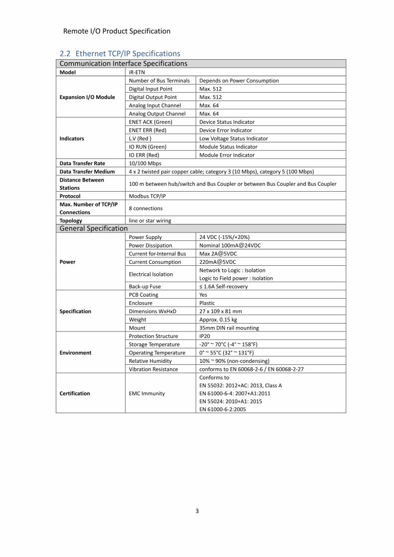
Ethernet TCP/IP Specifications 2.2Communication Interface Specifications Model iR-ETN
Expansion I/O Module
Number of Bus Terminals Depends on Power Consumption
Digital Input Point Max. 512
Digital Output Point Max. 512
Analog Input Channel Max. 64
Analog Output Channel Max. 64
Indicators
ENET ACK (Green) Device Status Indicator ENET ERR (Red) Device Error Indicator L.V (Red ) Low Voltage Status Indicator IO RUN (Green) Module Status Indicator IO ERR (Red) Module Error Indicator
Data Transfer Rate 10/100 Mbps
Data Transfer Medium 4 x 2 twisted pair copper cable; category 3 (10 Mbps), category 5 (100 Mbps) Distance Between
Stations 100 m between hub/switch and Bus Coupler or between Bus Coupler and Bus Coupler
Protocol Modbus TCP/IP
Max. Number of TCP/IP
Connections 8 connections
Topology line or star wiring
General Specification
Power
Power Supply 24 VDC (-15%/+20%) Power Dissipation Nominal 100mA@24VDC
Current for Internal Bus Max 2A@5VDC
Current Consumption 220mA@5VDC
Electrical Isolation Network to Logic : Isolation
Logic to Field power : Isolation
Back-up Fuse ≤ 1.6A Self-recovery
Specification
PCB Coating Yes Enclosure Plastic
Dimensions WxHxD 27 x 109 x 81 mm
Weight Approx. 0.15 kg
Mount 35mm DIN rail mounting
Environment
Protection Structure IP20
Storage Temperature -20° ~ 70°C (-4° ~ 158°F)Operating Temperature 0° ~ 55°C (32° ~ 131°F) Relative Humidity 10% ~ 90% (non-condensing) Vibration Resistance conforms to EN 60068-2-6 / EN 60068-2-27
Certification EMC Immunity
Conforms to
EN 55032: 2012+AC: 2013, Class A
EN 61000-6-4: 2007+A1:2011
EN 55024: 2010+A1: 2015
EN 61000-6-2:2005

Remote I/O Product Specification
4
3. Digital Input/Output
Digital Input Specifications 3.1Module Name iR-DI16-K iR-DM16-P iR-DM16-N
Number of Inputs 16 8 8
Input Logic Sink or Source
Current Consumption 5VDC,83mA 5VDC,130mA 5VDC,130mA
HIGH Level Input Voltage 15~28V VDC
LOW Level Input Voltage 0~5 VDC
Response Time
OFF->ON 5 ms
ON->OFF 1 ms
Input Impedance 5.6 KΩ
System Indicators Red Led Input State
Specification
PCB Coating No
Enclosure Plastic
Dimensions WxHxD 27 x 109 x 81 mm
Weight Approx. 0.12 kg
Mount 35mm DIN rail mounting
Environment
Protection Structure IP20
Storage Temperature -20° ~ 70°C (-4° ~ 158°F)
Operating Temperature 0° ~ 55°C (32° ~ 131°F)
Relative Humidity 10% ~ 90% (non-condensing)
Vibration Resistance Conforms to EN 60068-2-6 / EN 60068-2-27
Connection Cross-section AWG 28-16
Certification EMC Immunity
Conforms to EN 55032: 2012+AC: 2013, Class A EN 61000-6-4: 2007+A1:2011 EN 55024: 2010+A1: 2015 EN 61000-6-2:2005
Digital Output Specifications 3.2Module Name iR-DM16-P iR-DQ16-P iR-DM16-N iR-DQ16-N iR-DQ08-R Number of Outputs 8 16 8 16 8
Current Consumption 5VDC,130mA 5VDC,196mA 5VDC,130mA 5VDC,205mA 5VDC,220mA
Output Logic Source Sink Relay
Output Voltage 11~28VDC 11~28VDC 250VAC/ 30VDC
Output Current 0.5A per channel Max 4A) 0.5A per channel (Max 4A) 2A per channel (Max 8A)
Response Time
OFF→ON 300μs 300μs 10ms
ON→OFF
Specification
PCB Coating No
Enclosure Plastic
Dimensions WxHxD 27 x 109 x 81 mm
Weight Approx. 0.12 kg Approx. 0.13 kg
Mount 35mm DIN rail mounting
Environment
Protection Structure IP20
Storage Temperature -20° ~ 70°C (-4° ~ 158°F)
Operating Temperature 0° ~ 55°C (32° ~ 131°F)
Relative Humidity 10% ~ 90% (non-condensing)
Vibration Resistance Conforms to EN 60068-2-6 / EN 60068-2-27
Connection Cross-section AWG 28-16 AWG 24-16
Certification EMC Immunity
Conforms to EN 55032: 2012+AC: 2013, Class A EN 61000-6-4: 2007+A1:2011 EN 55024: 2010+A1: 2015 EN 61000-6-2:2005


Remote I/O Product Specification
6
4. Dimensions
iR-COP 4.1
a Node ID Rotary Switch x10 e Baud Rate DIP Switch
b Node ID Rotary Switch x1 f Expansion Connector
c CAN Bus Connector
d Power Connector
英文版 簡中版 日文版
Front View Side ViewSide View
Top View
Bottom View
ab
c
d
e
fab
c
d
e
fab
c
d
e
f
81mm [3.19"]
10
9m
m [
4.2
9"]
81mm [3.19"]
10
9m
m [
4.2
9"]
81mm [3.19"]
10
9m
m [
4.2
9"]
27mm [1.06"]27mm [1.06"]27mm [1.06"]

Remote I/O Product Specification
7
iR-ETN 4.2
a Reset Button e Expansion Connector
b LAN 1
c LAN 2
d Power Connector
英文版 簡中版 日文版
Front View Side ViewSide View
Top View
Bottom View
27mm [1.06"]
a
b
c
d
81mm [3.19"]
e
10
9m
m [
4.2
9"]
27mm [1.06"]
a
b
c
d
81mm [3.19"]
e
10
9m
m [
4.2
9"]
27mm [1.06"]
a
b
c
d
81mm [3.19"]
e
10
9m
m [
4.2
9"]

Remote I/O Product Specification
8
iR-DM16-N & P, iR-DQ16-N&P, iR-DI16-K, iR-DQ08-R 4.3
a Terminal b.c Expansion Connector
81mm [3.19"]
109
mm
[4
.29
"]
27mm [1.06"]
a
bc
27mm [1.06"]
a
iR-DXXX iR-DQ08-R
81mm [3.19"]
109
mm
[4
.29
"]
27mm [1.06"]
a
bc
27mm [1.06"]
a
iR-DXXX iR-DQ08-R
81mm [3.19"]
109
mm
[4
.29
"]
27mm [1.06"]
a
bc
27mm [1.06"]
a
iR-DXXX iR-DQ08-R
簡中版英文版 日文版
Bottom View
Side ViewSide View
Top View

Remote I/O Product Specification
9
www.kep.com
5. Power Consumption
Type Device Consumption(5V) Power Supply(5V)
Coupler iR-ETN 220mA/1.1w 2A/10w
iR-COP 170mA/0.85w 2A/10w
Digital I/O
iR-DM16-P 130mA/0.65w -- iR-DM16-N 130mA/0.65w -- iR-DQ08-R 220mA/1.1w -- iR-DQ16-N 205mA/1.02w
iR-DQ16-P 196mA/0.984w
iR-DI16-K 83mA/0.418w
Note:
The coupler is the only power supply for the modules in this system. Please consider power requirements
when connecting multiple modules.
ex.1 Device Name Consumption Power Supply
Coupler iR-COP 170mA/0.85w 2A/10w
Module iR-DQ08-R *8 220mA*8=1.76A X
System Power consumption ∶ 170mA + 1.76A = 1.93 A
Power supply: 2A > 1.93A
ex.2 Device Name Consumption Power Supply
Coupler iR-ETN 220mA/1.1w 2A/10w
Module iR-DM16-P *13 130mA*13=1.69A X
System Power consumption ∶ 220mA + 1.69A = 1.91 A
Power supply: 2A > 1.91A
iR_DataSheet_ENG_20180202