remote i/o user manual · i/o mapping i/o mapping for the series b versions of the analog modules...
TRANSCRIPT
User
Manual
Remote I/OAdapter Module
(Cat. No. 1794�ASB Series B)
Allen�Bradley

Because of the variety of uses for the products described in thispublication, those responsible for the application and use of this controlequipment must satisfy themselves that all necessary steps have been takento assure that each application and use meets all performance and safetyrequirements, including any applicable laws, regulations, codesand standards.
The illustrations, charts, sample programs and layout examples shown inthis guide are intended solely for example. Since there are many variablesand requirements associated with any particular installation, Allen-Bradleydoes not assume responsibility or liability (to include intellectual propertyliability) for actual use based upon the examples shown in this publication.
Allen-Bradley publication SGI–1.1, “Safety Guidelines For TheApplication, Installation and Maintenance of Solid State Control”(available from your local Allen-Bradley office) describes some importantdifferences between solid-state equipment and electromechanical deviceswhich should be taken into consideration when applying products such asthose described in this publication.
Reproduction of the contents of this copyrighted publication, in whole orin part, without written permission of Allen–Bradley Company, Inc.is prohibited.
Throughout this manual we make notes to alert you to possible injury topeople or damage to equipment under specific circumstances.
ATTENTION: Identifies information about practices orcircumstances that can lead to personal injury or death, propertydamage or economic loss.
Attention helps you:
Identify a hazard. Avoid the hazard. Recognize the consequences.
Important: Identifies information that is especially important forsuccessful application and understanding of the product.
Important: We recommend you frequently backup your applicationprograms on appropriate storage medium to avoid possible data loss.
Important User Information

Publication 1794�6.5.3 - May 1996
Summary of Changes
This publication contains new and revised information not includedin the last release.
New Information
Series A and Series B Differences
The remote I/O adapter is now a series B. The series A adapters andthe series B adapters process block transfers differently.
Series A adapters allow block transfers to continue to occur evenwhen an analog module is removed from its base.
With series B adapters, when a module is removed from its terminalbase, the series B adapter ceases to do block transfers to theprocessor and a block transfer error bit is set in the processor. Thisprovides feedback to the processor that a block transfer module hasbeen removed.
Important: The “hold inputs” feature, selectable on the switchassembly on the adapter, will not apply to analogmodules. If you need this feature, you must simulatethis feature in your programming.
Additional Flex I/O Modules
Three new FLEX I/O modules have been added to this publication.
• 1794-IB10XOB6 input/output combination module
• 1794-IR8 RTD input analog module
• 1794-IT8 Thermocouple/mV input analog module
European Union Directives Compliance
Information has been added to identify adherence to the requireddirectives when the module is CE marked.
Revised Information
Three analog modules have undergone a series change. Thesemodules are:
• 1794-OE4 series B 4 output analog module
• 1794-IE8 series B 8 input analog module
• 1794-IE4XOE2 series B 4 in/2 out combo analog module

Summary of ChangesSOC–2
Publication 1794�6.5.3 - May 1996
I/O Mapping
I/O mapping for the series B versions of the analog modules hasbeen added. In addition, the 1794-IR8 and 1794-IT8 module I/Omapping is also included.
Change Bars
The areas in this manual which are different from previous editionsare marked with change bars (as shown next to this paragraph) toindicate the addition of new or revised information.

Using This Manual P-1. . . . . . . . . . . . . . . . . . . . . . . . . . . . . . .
Preface Objectives P-1. . . . . . . . . . . . . . . . . . . . . . . . . . . . . . . . . . .
Audience P-1. . . . . . . . . . . . . . . . . . . . . . . . . . . . . . . . . . . . . . . . . .
Vocabulary P-1. . . . . . . . . . . . . . . . . . . . . . . . . . . . . . . . . . . . . . . .
What This Manual Contains P-1. . . . . . . . . . . . . . . . . . . . . . . . . . . .
Conventions P-2. . . . . . . . . . . . . . . . . . . . . . . . . . . . . . . . . . . . . . .
For Additional Information P-2. . . . . . . . . . . . . . . . . . . . . . . . . . . . . .
Summary P-2. . . . . . . . . . . . . . . . . . . . . . . . . . . . . . . . . . . . . . . . .
Summary of Changes SOC-1. . . . . . . . . . . . . . . . . . . . . . . .
New Information SOC-1. . . . . . . . . . . . . . . . . . . . . . . . . . . . . . . . .
Series A and Series B Differences SOC-1. . . . . . . . . . . . . . . . . .
Additional Flex I/O Modules SOC-1. . . . . . . . . . . . . . . . . . . . . . .
European Union Directives Compliance SOC-1. . . . . . . . . . . . . .
Revised Information SOC-1. . . . . . . . . . . . . . . . . . . . . . . . . . . . . .
I/O Mapping SOC-2. . . . . . . . . . . . . . . . . . . . . . . . . . . . . . . . . .
Change Bars SOC-2. . . . . . . . . . . . . . . . . . . . . . . . . . . . . . . . . . .
Overview of FLEX I/O and your Remote I/O Adapter Module 1-1
Chapter Objectives 1-1. . . . . . . . . . . . . . . . . . . . . . . . . . . . . . . . . . .
The FLEX I/O System 1-1. . . . . . . . . . . . . . . . . . . . . . . . . . . . . . . . .
How FLEX I/O Modules Communicate with Programmable Controllers 1-2. . . . . . . . . . . . . . . . . . . . . . . . . . .
Hardware Components 1-3. . . . . . . . . . . . . . . . . . . . . . . . . . . . . . . .
Diagnostic Indicators 1-3. . . . . . . . . . . . . . . . . . . . . . . . . . . . . . .
Reset Pushbutton 1-4. . . . . . . . . . . . . . . . . . . . . . . . . . . . . . . . .
Remote I/O Wiring 1-4. . . . . . . . . . . . . . . . . . . . . . . . . . . . . . . . .
Power Wiring 1-4. . . . . . . . . . . . . . . . . . . . . . . . . . . . . . . . . . . . .
Address Switch Assemblies 1-4. . . . . . . . . . . . . . . . . . . . . . . . . .
Chapter Summary 1-4. . . . . . . . . . . . . . . . . . . . . . . . . . . . . . . . . . .
Installing Your Remote I/O Adapter Module 2-1. . . . . . . . . . . .
Chapter Objectives 2-1. . . . . . . . . . . . . . . . . . . . . . . . . . . . . . . . . . .
European Union Directive Compliance 2-1. . . . . . . . . . . . . . . . . . . . .
EMC Directive 2-1. . . . . . . . . . . . . . . . . . . . . . . . . . . . . . . . . . . .
Low Voltage Directive 2-1. . . . . . . . . . . . . . . . . . . . . . . . . . . . . . .
Power Requirements 2-2. . . . . . . . . . . . . . . . . . . . . . . . . . . . . . . . .
Mounting the Remote I/O Adapter 2-2. . . . . . . . . . . . . . . . . . . . . . . .
Mounting on the DIN Rail 2-2. . . . . . . . . . . . . . . . . . . . . . . . . . . .
Mounting on a Wall or Panel 2-3. . . . . . . . . . . . . . . . . . . . . . . . . .
Wiring 2-5. . . . . . . . . . . . . . . . . . . . . . . . . . . . . . . . . . . . . . . . . . . .
Table of Contents

Table of Contentsii
Setting the Switches 2-6. . . . . . . . . . . . . . . . . . . . . . . . . . . . . . . . . .
Starting I/O Group 2-6. . . . . . . . . . . . . . . . . . . . . . . . . . . . . . . . .
I/O Rack Number 2-6. . . . . . . . . . . . . . . . . . . . . . . . . . . . . . . . . .
Hold Inputs 2-6. . . . . . . . . . . . . . . . . . . . . . . . . . . . . . . . . . . . . .
Last Chassis 2-6. . . . . . . . . . . . . . . . . . . . . . . . . . . . . . . . . . . . .
Reply Delay 2-6. . . . . . . . . . . . . . . . . . . . . . . . . . . . . . . . . . . . . .
Communication Rate 2-7. . . . . . . . . . . . . . . . . . . . . . . . . . . . . . .
Processor Restart Lockout 2-7. . . . . . . . . . . . . . . . . . . . . . . . . . .
Hold Last State 2-7. . . . . . . . . . . . . . . . . . . . . . . . . . . . . . . . . . .
Chapter Summary 2-10. . . . . . . . . . . . . . . . . . . . . . . . . . . . . . . . . . .
Communicating with FLEX I/O Modules 3-1. . . . . . . . . . . . . . .
Chapter Objectives 3-1. . . . . . . . . . . . . . . . . . . . . . . . . . . . . . . . . . .
Hardware Addressing 3-1. . . . . . . . . . . . . . . . . . . . . . . . . . . . . . . . .
Determining Rack Size 3-2. . . . . . . . . . . . . . . . . . . . . . . . . . . . . . . .
Mapping Data into the Image Tables 3-4. . . . . . . . . . . . . . . . . . . . . .
Discrete I/O Modules 3-4. . . . . . . . . . . . . . . . . . . . . . . . . . . . . . .
16�point Discrete Input Module Image Table Mapping - 1794�IB16 3-5
Memory Map of 16�Point Discrete Input Module Image Table - 1794�IB16 3-5. . . . . . . . . . . . . . . . . . . . . . . . . . . . .
Input Delay Times for the 1794�IB16 Input Module 3-5. . . . . . . . .
16�point Discrete Output Module Image Table Mapping - 1794�OB16 3-6. . . . . . . . . . . . . . . . . . . . . . .
Memory Map of 16�Point Discrete Output Module Image Table - 1794�OB16 3-6. . . . . . . . . . . . . . . . . . . . . . . . . . . .
8�point Discrete Input Module Image Table Mapping - 1794�IB8S 3-6
Memory Map of 8�Point Discrete Input Module Image Table (with Status) - 1794�IB8S 3-6. . . . . . . . . . . . . . . . . . .
Input Delay Times for the 1794�IB8S Input Module 3-7. . . . . . . .
16�point Discrete Input/Output Module Image Table Mapping -1794�IB10XOB6 3-7. . . . . . . . . . . . . . . . . . . . . . . . . . . . . . . .
Memory Map of 16�Point Discrete Input/Output Module Image Table - 1794�IB10XOB6 3-7. . . . . . . . . . . . . . . . . . .
8�point Discrete Input Module Image Table Mapping - 1794�IA8 3-8.
Memory Map of 8�point Discrete Input Module Image Table - 1794�IA8 3-8. . . . . . . . . . . . . . . . . . . . . . . . . . . . . .
Input Delay Times for the 1794�IA8 Input Module 3-8. . . . . . . . .
8�point Discrete Output Module Image Table Mapping - 1794�OA8 3-9
Memory Map of 8�Point Discrete Output Module Image Table - 1794�OA8 3-9. . . . . . . . . . . . . . . . . . . . . . . . . . . . .
8�point Discrete Relay Output Module Image Table Mapping - 1794�OW8 3-9. . . . . . . . . . . . . . . . . . . . . . .
Memory Map of 8�Point Discrete Output Module Image Table - 1794�OW8 3-9. . . . . . . . . . . . . . . . . . . . . . . . . . . .
Analog I/O Modules 3-10. . . . . . . . . . . . . . . . . . . . . . . . . . . . . . . .
8 Input Analog Module (Cat. No. 1794�IE8 Series B) 3-11. . . . . . . . .
Analog Input Module (1794�IE8/B) Read 3-11. . . . . . . . . . . . . . .
Table of Contents iii
Analog Input Module (1794�IE8/B) Write Configuration Block 3-11.
Range Selection Bits for the 1794�IE8/B Analog Input Module 3-12
4 Output Analog Module (Cat. No. 1794�OE4 Series B) 3-12. . . . . . .
Analog Output Module (1794�OE4) Read 3-12. . . . . . . . . . . . . . .
Analog Output Module (1794�OE4/B) Write Configuration Block 3-13
Range Selection Bits for the 1794�OE4/B Analog Output Module (Word 5) 3-13. . . . . . . . . . . . . . . . . . . . . . . . . . . . . .
4 Input/2 Output Analog Combo Module (Cat. No. 1794�IE4XOE2 Series B) 3-14. . . . . . . . . . . . . . . . . . .
Analog Combo Module (1794�IE4XOE2/B) Read 3-14. . . . . . . . .
Analog Combo Module (1794�IE4XOE2/B) Write Configuration Block 3-14. . . . . . . . . . . . . . . . . . . . . . . . . . . .
Range Selection Bits for the 1794�IE4XOE2/B Analog Combo Module 3-15. . . . . . . . . . . . . . . . . . . . . . . . . . . . . . .
RTD Input Module (1794�IR8) Image Table Mapping 3-16. . . . . . . . .
RTD Analog Input Module (1794�IR8) Read Words 3-16. . . . . . . .
RTD Analog Input Module (1794�IR8) Write Words 3-17. . . . . . . .
Thermocouple/mV Input Module (1794�IT8) Image Table Mapping 3-17
Thermocouple/mV Input Module (1794�IT8) Read 3-17. . . . . . . . .
Thermocouple/mV Input Module (1794�IT8) Write 3-18. . . . . . . . .
Operating Modes 3-18. . . . . . . . . . . . . . . . . . . . . . . . . . . . . . . . . . . .
Chapter Summary 3-18. . . . . . . . . . . . . . . . . . . . . . . . . . . . . . . . . . .
Troubleshooting 4-1. . . . . . . . . . . . . . . . . . . . . . . . . . . . . . . .
Chapter Objectives 4-1. . . . . . . . . . . . . . . . . . . . . . . . . . . . . . . . . . .
Fault Conditions 4-1. . . . . . . . . . . . . . . . . . . . . . . . . . . . . . . . . . . . .
Troubleshooting with the Indicator Lights 4-1. . . . . . . . . . . . . . . . . . .
Table 4.ARemote I/O System Troubleshooting Guide 4-2. . . . . . . . . . . . . . .
Chapter Summary 4-3. . . . . . . . . . . . . . . . . . . . . . . . . . . . . . . . . . .
Specifications A-1. . . . . . . . . . . . . . . . . . . . . . . . . . . . . . . . . .
Support Services 4-1. . . . . . . . . . . . . . . . . . . . . . . . . . . . . . . . . . . .
Technical Support 4-1. . . . . . . . . . . . . . . . . . . . . . . . . . . . . . . . .
Engineering and Field Services 4-1. . . . . . . . . . . . . . . . . . . . . . . .
Technical Training 4-1. . . . . . . . . . . . . . . . . . . . . . . . . . . . . . . . .
Repair and Exchange Services 4-1. . . . . . . . . . . . . . . . . . . . . . . .

Preface
Publication 1794�6.5.3 - May 1996
Using This Manual
Read this preface to familiarize yourself with this manual and tolearn how to use it properly and efficiently.
We assume that you have previously used an Allen–Bradleyprogrammable controller, that you are familiar with its features, andthat you are familiar with the terminology we use. If not, read theuser manual for your processor before reading this manual.
In this manual, we refer to:
• the individual adapter module as the “adapter.”
• the programmable controller as the “controller” or the“processor.”
• input and output modules as the “module.”
The contents of this manual are as follows:
Table P. AWhat This Manual Contains
Chapter Title What's Covered
1Overview of FLEX I/O and the RemoteI/O Adapter Module
Describes features, capabilities, and hardwarecomponents.
2 Installing Your Remote I/O Adapter Procedures and guidelines for installing the module
3 Communicating with FLEX I/O Modules Hardware addressing and configuration options
4 Troubleshooting Troubleshooting aids
Appendix Title What's Covered
A Specifications Module specifications
Preface Objectives
Audience
Vocabulary
What This ManualContains
Using This ManualP–2
Publication 1794�6.5.3 - May 1996
We use these conventions in this manual:
In this manual, we show: Like this:
that there is more information about a topicin another chapter in this manual
that there is more information about thetopic in another manual
More
For additional information on FLEX I/O systems and modules, referto the following documents:
CatalogPublications
CatalogNumber
Voltage Description InstallationInstructions
UserManual
1794 1794 FLEX I/O Product Data 1794�2.1
1794�ACN 24V dc ControlNet Adapter 1794�5.8
1794�ADN 24V dc DeviceNet Adapter 1794�5.14 1794�6.5.5
1794�ASB 24V dc Remote I/O Adapter 1794�5.11 1794�6.5.3
1794�TB21794�TB3
2�wire Terminal Base3�wire Terminal Base
1794�5.2
1794�TBN Terminal Base Unit 1794�5.16
1794�TBNF Fused Terminal Base Unit 1794�5.17
1794�TB3T Temperature Terminal Base Unit 1794�5.41
1794�IB16 24V dc 16 Input Module 1794�5.4
1794�OB16 24V dc 16 Output Module 1794�5.3
1794�IB10XOB6 24V dc 10 Input/6 Output Module 1794�5.24
1794�IE8 24V dc Selectable Analog 8 Input Module 1794�5.6
1794�OE4 24V dc Selectable Analog 4 Output Module 1794�5.5 1794�6.5.2
1794�IE4XOE2 24V dc 4 Input/2 Output Analog Module 1794�5.15
1794�IR8 24V dc 8 RTD Input Analog Module 1794�5.22 1794�6.5.4
1794�IT8 24V dc 8 Thermocouple Input Module 1794�5.21 1794�6.5.7
1794�IB8S 24V dc Sensor Input Module 1794�5.7
1794�IA8 120V ac 8 Input Module 1794�5.9
1794�OA8 120V ac Output Module 1794�5.10
1794�CE1 Extender Cable 1794�2.12
1794�NM1 Mounting Kit 1794�2.13
1794�PS1 24V dc Power Supply 1794�5.35
This preface gave you information on how to use this manualefficiently. The next chapter introduces you to the remote I/Oadapter module.
Conventions
For Additional Information
Summary

Chapter 1
Publication 1794�6.5.3
Overview of FLEX I/O and yourRemote I/O Adapter Module
In this chapter, we tell you about:
• what the FLEX I/O system is and what it contains
• how FLEX I/O modules communicate with programmablecontrollers
• the features of your adapter module
FLEX I/O is a small, modular I/O system for distributedapplications that performs all of the functions of rack-based I/O. TheFLEX I/O system contains the following components shown below:
Adapter Terminal Base
I/O Module
20125
• adapter/power supply – powers the internal logic for as many aseight I/O modules
• terminal base – contains a terminal strip to terminate wiring fortwo- or three-wire devices
• I/O module – contains the bus interface and circuitry needed toperform specific functions related to your application
Chapter Objectives
The FLEX I/O System

1–2 Overview of FLEX I/O and your Remote I/O Adapter Module
Publication 1794�6.5.3 - May 1996
Data transfer to and from the remote I/O adapter/power supply anddiscrete I/O modules occurs every flexbus scan. This provides thecontroller with updated data.
The remote I/O adapter/power supply transfers data to the analog I/Omodule (block transfer write) and from the analog I/O module (blocktransfer read) using BTW and BTR instructions in your ladderdiagram program. These instructions let the adapter obtain inputvalues and status from the I/O module, and let you send outputvalues to establish the module’s mode of operation. Thecommunication process is described in the following illustration.
ADAPTER
ACTIVE FAULTLOCALFAULT
24VDCPOWER SUPPLY
RIO ADAPTER
1794�ASB
Allen�Bradley
2
Allen�Bradley
INPUT 0 INPUT 2 INPUT 4 INPUT 6INPUT 1 INPUT 3 INPUT 5 INPUT 7I V I V I V I V I V I V I V I V
ANALOG INPUT
1794-IE8
1
The adapter transfers your configuration datato the module using a BTW.
Flexbus
External devices transmitanalog signals to the module.
2
The module converts analog signalsinto binary format and stores thesevalues until the adapter requests theirtransfer.
3
Your ladder program instructs theadapter to perform a BTR of the valuesand stores them in a data table.
4
The adapter and module determinethat the transfer was made without errorand input values are within specifiedrange.
5
Your ladder program can use and/or move the data (if valid)before it is written over by the transfer of new data in a subsequent transfer.
6
Your ladder program performs BTWs to the module when you powerit up, and any time you wish to reconfigure the module.
7
How FLEX I/O ModulesCommunicate withProgrammable Controllers

1–3Overview of FLEX I/O and your Remote I/O Adapter Module
Publication 1794�6.5.3 - May 1996
The adapter module consists of the following major components:
• diagnostic indicators
• reset pushbutton
• remote I/O wiring connections
• 24V dc power wiring connections
• address/group switch assemblies
Diagnostic Indicators
Reset Pushbutton
+24V dc Wiring Connections
24V dc Common Wiring Connections
Remote I/O Wiring Connections (connector part no. 942029-03)
Address/Group Switches
Allen�Bradley
24 VDCPOWER SUPPLY
RIO ADAPTER1794-ASB
ADAPTER
ACTIVE FAULT
LOCAL
FAULT
Diagnostic Indicators
Diagnostic indicators are located on the front panel of the adaptermodule. They show both normal operation and error conditions inyour remote I/O system. The indicators are:
• Adapter ACTIVE (green)• Adapter FAULT (red)• LOCAL FAULT (red)
A complete description of the diagnostic indicators and how to usethem for troubleshooting is explained in chapter 4.
Hardware Components

1–4 Overview of FLEX I/O and your Remote I/O Adapter Module
Publication 1794�6.5.3 - May 1996
Reset Pushbutton
Use the reset pushbutton to reset the adapter module and resumecommunication when a communication error occurs. (The adapter’s processor restart lockout switch (PRL) must be in the “locked out”position.) If the adapter is not locked out by the PRL switch, it will be automatically reset via special commands sent over thecommunication link.
Important: Do not cycle power to the adapter to clear a fault. Allqueued block transfer instructions will be lost.
Remote I/O Wiring
The remote I/O wiring termination is made to a plug-in connector onthe front of the adapter module. Refer to Chapter 2 for informationon wiring the connector.
Power Wiring
Connections are provided for connecting the required 24V dc powerto the front of the module. The power wiring can be daisy-chained tothe terminal base unit located next to the adapter to supply power tothe module installed in that base unit. Wiring information is shown inChapter 2.
Address Switch Assemblies
Multi-position switches are provided for:
• starting I/O group – 0, 2, 4 or 6
• rack number
• hold inputs – hold or reset
• last chassis – yes or no
• reply delay – this switch position should always be on
• communication rate – 57.6, 115.2, or 230.4k bits/s
• processor restart lockout (PRL)
• hold last state (for outputs)
These switches are accessed by lifting the hinged cover on the frontof the module. Refer to Chapter 2 for switch settings.
In this chapter you learned about the FLEX I/O system and featuresof the remote I/O adapter module.
87
65
43
21
87
65
43
21
ONON
S1 S2
Flip�opencover
Chapter Summary

Chapter 2
Publication 1794�6.5.3
Installing Your Remote I/OAdapter Module
This chapter describes the procedures for installing your remote I/Oadapter module. These include:
• power requirements
• mounting the remote I/O adapter
• setting the module switches
If this product has the CE mark it is approved for installation withinthe European Union and EEA regions. It has been designed andtested to meet the following directives.
EMC Directive
This product is tested to meet Council Directive 89/336/EECElectromagnetic Compatibility (EMC) and the following standards,in whole or in part, documented in a technical construction file:
• EN 50081-2EMC – Generic Emission Standard, Part 2 –Industrial Environment
• EN 50082-2EMC – Generic Immunity Standard, Part 2 –Industrial Environment
This product is intended for use in an industrial environment.
Low Voltage Directive
This product is tested to meet Council Directive 73/23/EECLow Voltage, by applying the safety requirements of EN 61131–2Programmable Controllers, Part 2 – Equipment Requirements andTests.
For specific information required by EN 61131-2, see the appropriatesections in this publication, as well as the following Allen-Bradleypublications:
• Industrial Automation Wiring and Grounding Guidelines ForNoise Immunity, publication 1770-4.1
• Guidelines for Handling Lithium Batteries, publication AG-5.4
• Automation Systems Catalog, publication B111
Chapter Objectives
European Union DirectiveCompliance

2–2 Installing Your Remote I/O Adapter Module
Publication 1794�6.5.3 - May 1996
The Remote I/O adapter module requires a current of 450mA at24V dc from an external power supply for flexbus operation. This issufficient to support the flexbus current requirements one logicalrack (8 modules). Remember to add this amount to currentrequirements for other modules using the same 24V supply.
The remote I/O adapter module can be DIN rail or wall/panelmounted. Refer to the specific method of mounting below.
Mounting on the DIN Rail
B
C
A
C
1. Position the remote I/O adapter module A on a 35 x 7.5mm DINrail B (A-B pt. no. 199-DR1; 46277-3; EN 50022) at a slightangle.
2. Rotate the adapter module onto the DIN rail with the top of therail hooked under the lip on the rear of the adapter module.
3. Press the adapter module down onto the DIN rail until flush.Locking tab (C) will snap into position and lock the adaptermodule to the DIN rail.
If the adapter module does not lock in place, use a screwdriver orsimilar device to move the locking tab down while pressing theadapter module flush onto the DIN rail and release the locking tabto lock the adapter module in place. If necessary, push up on thelocking tab to lock.
4. Connect the adapter wiring as shown under “Wiring” later in thisdocument.
Important: Make certain that the DIN rail is properly grounded tothe panel. Refer to “Industrial Automation Wiring andGrounding Guidelines for Noise Immunity,” publication1770-4.1.
More
Power Requirements
Mounting the Remote I/OAdapter

2–3Installing Your Remote I/O Adapter Module
Publication 1794�6.5.3 - May 1996
Mounting on a Wall or Panel
To mount the remote I/O adapter module on a wall or panel, youmust have the 1794-NM1 mounting kit. The kit contains a specialplate and screws necessary for wall/panel mounting. Proceed asfollows:
Install the mounting plate on a wall or panel as follows:
1. Lay out the required points on the wall/panel as shown in thedrilling dimension drawing.
1.4(35)
Inches(Millimeters)
3.4(87)
3.2(80)
2.7(68) 3.7
(94)
3.2(80)
3.7(94)
1794 Terminal Base Units3.7H x 3.7W x 2.7D(94H x 94W x 69D)
.83 (21)
0.9(23)2.3
(59)
1794 Adapters3.4H x 2.7W x 2.7D(87H x 68W x 69D)
1.4(35)
3.7(94)
2.0(50)
1.2(30)
A
A = Mounting hole dimensions for optional mounting kit
2. Drill the necessary holes for #6 self-tapping mounting screws.
3. Mount the mounting plate (1) for the adapter module using two#6 self-tapping screws (18 included).
Important: Make certain that the mounting plate is properlygrounded to the panel. Refer to “Industrial AutomationWiring and Grounding Guidelines for Noise Immunity,”publication 1770-4.1.
More

2–4 Installing Your Remote I/O Adapter Module
Publication 1794�6.5.3 - May 1996
1.4(35.5)
1 - Adapter Mounting Plate
2 - Remote I/O Adapter Module
Mounting Screws(18) -2 for the mounting plate
and 2 each for the 8possible modules
4. Hold the adapter (2) at an angle and engage the top of themounting plate in the indention on the rear of the adapter module.
5. Press the module down flush with the panel until the lockinglever locks.
6. Position the termination base unit up against the adapter and pushthe female bus connector into the adapter.
7. Secure to the wall with two #6 self-tapping screws.
8. Repeat for each remaining terminal base unit.
Note: The adapter is capable of addressing eight modules. Do notexceed a maximum of eight terminal base units in your system.
2–5Installing Your Remote I/O Adapter Module
Publication 1794�6.5.3 - May 1996
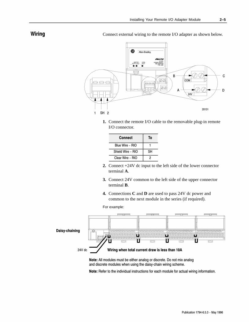
Connect external wiring to the remote I/O adapter as shown below.
1 SH 2
B C
DA
20131
24V
COM
Allen�Bradley
24 VDCPOWER SUPPLY
RIO ADAPTER1794-ASB
ADAPTERACTIVE FAULT
LOCALFAULT
1. Connect the remote I/O cable to the removable plug-in remoteI/O connector.
Connect To
Blue Wire - RIO 1
Shield Wire - RIO SH
Clear Wire - RIO 2
2. Connect +24V dc input to the left side of the lower connectorterminal A.
3. Connect 24V common to the left side of the upper connectorterminal B.
4. Connections C and D are used to pass 24V dc power andcommon to the next module in the series (if required).
For example:
Wiring when total current draw is less than 10A
Daisy�chaining
24V dc
Note: Refer to the individual instructions for each module for actual wiring information.
Note: All modules must be either analog or discrete. Do not mix analog and discrete modules when using the daisy�chain wiring scheme.
Wiring

2–6 Installing Your Remote I/O Adapter Module
Publication 1794�6.5.3 - May 1996
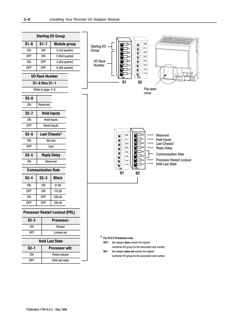
The remote I/O adapter module has two 8-position switch assemblieswhich you set for:
• starting I/O group
• I/O rack number
• hold inputs
• last chassis
• reply delay (always on)
• communication rate
• processor restart lockout (PRL)
• hold last state (outputs)
Starting I/O Group
The starting I/O group is the first group of input and output circuitsthat correspond to one word in both the input and output imagetables. These starting I/O groups are numbered 0, 2, 4 and 6. InFLEX I/O, one I/O group corresponds to one I/O module.
I/O Rack Number
One I/O rack number is 8 I/O groups. One FLEX I/O module isdesignated as 1 I/O group (1 word of input and 1 word of output).You cannot have more than 1 rack number per adapter. For anexample, refer to “Determining Rack Size” on page 3–2.
Hold Inputs
When hold inputs is enabled (S2-7 on), the adapter will retain thelast memory image present when you remove the discrete modulefrom its base. These inputs are held until the correct module isplaced back in the base. If the same type of module is reinserted intothe base, its inputs will be transferred. If a different type of module isinserted in the base, its memory image will go to zero. Anyassociated outputs will also go to zero.
Last Chassis
When last chassis is enabled (S2-6 off), this adapter contains thehighest numbered I/O group for the associated rack number. (Thisswitch is used for PLC-2 processors only.)
Reply Delay
This switch position is reserved for future use. This switch shouldalways be on.
Setting the Switches
2–7Installing Your Remote I/O Adapter Module
Publication 1794�6.5.3 - May 1996
Communication Rate
You set these switches (S2-3 and S2-4) for the desiredcommunication rate (in bits/s). Selections are:57.6k bits/s115.2k bits/s230.4k bits/s
Processor Restart Lockout
When PRL is disabled (switch S2-2 on), the programmablecontroller can restart communication with the adapter in the event ofa communication fault.
When PRL is enabled (switch S2-2 off), the programmable controllercannot restart communication with the adapter in the event of acommunication fault. In this case, you must press the restartpushbutton on the front of the adapter module to restartcommunication.
Hold Last State
During a communication error, when last state is enabled (S2-1 set tooff), a processor reset will keep the discrete outputs in their present(last) state; when last state is disabled, the discrete outputs will reset.
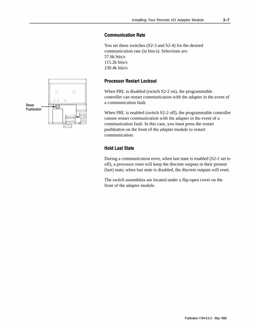
The switch assemblies are located under a flip-open cover on thefront of the adapter module.
ResetPushbutton
2–8 Installing Your Remote I/O Adapter Module
Publication 1794�6.5.3 - May 1996
Starting I/O Group
S1-8 S1-7 Module group
ON ON 0 (1st quarter)
OFF ON 2 (2nd quarter)
ON OFF 4 (3rd quarter)
OFF OFF 6 (4th quarter)
I/O Rack Number
S1-6 thru S1-1
Refer to page 2-9
S2-8
ON Reserved
S2-7 Hold Inputs
ON Hold Inputs
OFF Reset Inputs
S2-6 Last Chassis1
ON Not last
OFF Last
S2-5 Reply Delay
ON Reserved
Communication Rate
S2-4 S2-3 Bits/s
ON ON 57.6k
OFF ON 115.2k
ON OFF 230.4k
OFF OFF 230.4k
Processor Restart Lockout (PRL)
S2-2 Processor:
ON Restart
OFF Locked out
Hold Last State
S2-1 Processor will:
ON Reset outputs
OFF Hold last state
Flip�opencover
87
65
43
21
87
65
43
21
ONON
S1 S2
Starting I/O Group
I/O Rack Number
87
65
43
21
87
65
43
21
ONON
S1 S2
Hold Last StateProcessor Restart Lockout
Communication Rate
Reply Delay
Last Chassis1Hold Inputs
Reserved
1 For PLC�2 Processors only -
OFF - this adapter does contain the highest
numbered I/O group for the associated rack number.
ON - this adapter does not contain the highest
numbered I/O group for the associated rack number.

2–9Installing Your Remote I/O Adapter Module
Publication 1794�6.5.3 - May 1996
Rack Number S1 Switch Position
1747�SN 1771�SN PLC�2 PLC�5 PLC�5/250 PLC�3 6 5 4 3 2 1
Rack 0 Rack 1 Rack 1 Not Valid Rack 0 Rack 0 ON ON ON ON ON ON
Rack 1 Rack 2 Rack 2 Rack 1 Rack 1 Rack 1 OFF ON ON ON ON ON
Rack 2 Rack 3 Rack 3 Rack 2 Rack 2 Rack 2 ON OFF ON ON ON ON
Rack 3 Rack 4 Rack 4 Rack 3 Rack 3 Rack 3 OFF OFF ON ON ON ON
Rack 5 Rack 5 Rack 4 Rack 4 Rack 4 ON ON OFF ON ON ON
Rack 6 Rack 6 Rack 5 Rack 5 Rack 5 OFF ON OFF ON ON ON
Rack 7 Rack 7 Rack 6 Rack 6 Rack 6 ON OFF OFF ON ON ON
Rack 7 Rack 7 Rack 7 OFF OFF OFF ON ON ON
Rack 10 Rack 10 Rack 10 ON ON ON OFF ON ON
Rack 11 Rack 11 Rack 11 OFF ON ON OFF ON ON
Rack 12 Rack 12 Rack 12 ON OFF ON OFF ON ON
Rack 13 Rack 13 Rack 13 OFF OFF ON OFF ON ON
Rack 14 Rack 14 Rack 14 ON ON OFF OFF ON ON
Rack 15 Rack 15 Rack 15 OFF ON OFF OFF ON ON
Rack 16 Rack 16 Rack 16 ON OFF OFF OFF ON ON
Rack 17 Rack 17 Rack 17 OFF OFF OFF OFF ON ON
Rack 20 Rack 20 Rack 20 ON ON ON ON OFF ON
Rack 21 Rack 21 Rack 21 OFF ON ON ON OFF ON
Rack 22 Rack 22 Rack 22 ON OFF ON ON OFF ON
Rack 23 Rack 23 Rack 23 OFF OFF ON ON OFF ON
Rack 24 Rack 24 Rack 24 ON ON OFF ON OFF ON
Rack 25 Rack 25 Rack 25 OFF ON OFF ON OFF ON
Rack 26 Rack 26 Rack 26 ON OFF OFF ON OFF ON
Rack 27 Rack 27 Rack 27 OFF OFF OFF ON OFF ON
Rack 30 Rack 30 ON ON ON OFF OFF ON
Rack 31 Rack 31 OFF ON ON OFF OFF ON
Rack 32 Rack 32 ON OFF ON OFF OFF ON
Rack 33 Rack 33 OFF OFF ON OFF OFF ON
Rack 34 Rack 34 ON ON OFF OFF OFF ON
Rack 35 Rack 35 OFF ON OFF OFF OFF ON
Rack 36 Rack 36 ON OFF OFF OFF OFF ON
Rack 37 Rack 37 OFF OFF OFF OFF OFF ON
Rack 40 ON ON ON ON ON OFF
Rack 41 OFF ON ON ON ON OFF
Rack 42 ON OFF ON ON ON OFF
Rack 43 OFF OFF ON ON ON OFF
Rack 44 ON ON OFF ON ON OFF
Rack 45 OFF ON OFF ON ON OFF
Rack 46 ON OFF OFF ON ON OFF
Rack 47 OFF OFF OFF ON ON OFF
Rack 50 ON ON ON OFF ON OFF

2–10 Installing Your Remote I/O Adapter Module
Publication 1794�6.5.3 - May 1996
Chapter 3
Publication 1794�6.5.3
Communicating withFLEX I/O Modules
In this chapter, we tell you about:
• addressing your I/O• what combination of I/O modules and I/O chassis you can use• I/O image table usage
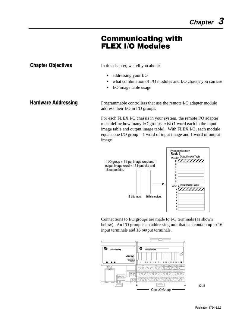
Programmable controllers that use the remote I/O adapter moduleaddress their I/O in I/O groups.
For each FLEX I/O chassis in your system, the remote I/O adaptermust define how many I/O groups exist (1 word each in the inputimage table and output image table). With FLEX I/O, each moduleequals one I/O group – 1 word of input image and 1 word of outputimage.
1 I/O group = 1 input image word and 1output image word = 16 input bits and16 output bits.
xxxxxxxx
Output Image TableWord #
Input Image TableWord #
16 bits input 16 bits output
ÉÉÉÉÉÉÉÉÉÉÉÉ
ÉÉÉÉÉÉ
Processor Memory
xxxxxxxx
Rack #
Connections to I/O groups are made to I/O terminals (as shownbelow). An I/O group is an addressing unit that can contain up to 16input terminals and 16 output terminals.
20126
24VDCPOWER SUPPLY
RIO ADAPTER
Allen�Bradley
1794�ASB
2
Allen�Bradley
0 1 2 3 4 5 6 7 8 9 10 11 12 13 14 15
One I/O Group
Chapter Objectives
Hardware Addressing

3–2 Communicating with FLEX I/O Modules
Publication 1794�6.5.3 - May 1996
I/O racks are made up of I/O groups. An I/O rack is an addressingunit that can contain up to eight I/O groups.
You can use as many as 8 modules per adapter. This provides amaximum of 128 discrete I/O or 64 analog inputs, or 32 analogoutput channels.
Figure 1An I/O Rack � Up to Eight I/O Groups
Any combination of discrete digital or analog modules.
Eight terminal bases (maximum)Adapter
20128Each terminal base represents 1 I/O group
Group 0 Group 1 Group 2 Group 3 Group 4 Group 5 Group 6 Group 7
Group 0 Group 1 Group 2 Group 3 Group 4
Group 7 Group 6 Group 5
Optional 1794�CE1 or �CE3 Extender Cable
When using the optional extender cable, modules groups are numbered sequentially along the length of the string. Do not use the extender cable to connect the adapter to the first module
Important: Only 1 extender cable is allowed per system.
After the remote I/O adapter has identified the modules present in itssystem, it creates a “rack image” so data transfer can take place usingthe remote I/O protocol.
Building a rack image consists of:• mapping each module to one I/O group (16 bits of input and 16
bits of output)
• determining rack size – all empty terminal bases are countedunless they occur at the end of the rack
• automatically sizing the rack image
!ATTENTION: Do not use the auto-config feature of6200 software when using a PLC-3 processor with1775-S4A or 1775-S4B scanner modules. If you do anauto-config for a scanner channel containing 1 or more1794-ASB adapters with that configuration, theadapters may not show up in the scan list for thatscanner channel. Manually insert these adapters intothe scan list for the scanner.
Determining Rack Size

3–3Communicating with FLEX I/O Modules
Publication 1794�6.5.3 - May 1996
Some examples of rack definition are shown below.
Adapter
Adapter
Each module is equal to 1 I/O group. Therefore, there are 4 I/O groups to be created. Four I/O groups equal1/2 of a logical rack. The remote I/O adapter will see this configuration as 1/2 of a logical rack
Each module is equal to 1 I/O group. The first empty terminal base is counted as 1 I/O group since it is not at theend of the rack. The second and third empty bases are not counted since they are at the end of the rack.Therefore, there are 5 I/O groups to be created. Five I/O groups are greater than 1/2 rack but less than 3/4 rack.The remote I/O adapter will see this configuration as the next highest rack, in this case, 3/4 of a logical rack withthe last I/O groups not mapped.
= 1/2 Rack
= 1/2 Rack
Module Empty Empty EmptyModule Module Module
Module Module Module Module
Adapter Module Empty Empty EmptyModuleEmpty
= 3/4 Rack
Each module is equal to 1 I/O group. The first and second empty terminal bases are counted as 1 I/O group each,since they are not at the end of the rack. The third and fourth empty bases are not counted since they are at theend of the rack. Therefore, there are 4 I/O groups to be created. Four I/O groups are equal to 1/2 rack. Theremote I/O adapter will see this configuration as 1/2 of a logical rack.
Example 1 - 4 Terminal Bases, 4 Modules
Example 2 - 6 Terminal Bases, 2 Modules
Example 3 - 7 Terminal Bases, 4 Modules
Adapter
StartingModuleGroup 4
4 5 6 7 0 1 2 3
Do not attempt to mix module groups from separate logical I/O rack numbers. All I/O module groups mustbe in the same logical I/O rack.
Example 4 - Illegal Module Grouping - An illegal grouping consists of more than 1 logical I/O rack attached to 1 adapter.

3–4 Communicating with FLEX I/O Modules
Publication 1794�6.5.3 - May 1996
After the rack size has been determined by the remote I/O adapter,the data from the modules must be mapped into the data tables.Mapping of data into the data table is different for discrete digitaland analog modules.
Data transfer to and from the remote I/O adapter and discrete digitalmodules occurs every flexbus scan. This data is mapped into theinput/output image table.
The remote I/O adapter transfers data to analog I/O modules (blocktransfer write) and from analog I/O modules (block transfer read)using BTW and BTR instructions in your ladder diagram program.This data is mapped to the data files selected in the ladder logicblock transfer instructions.
The adapter identifies the type of module in each base unit atpowerup, and stores this information for later use, if necessary.
Important: If you are changing your configuration, you must powerdown, then power back up after changing a module typein a terminal base unit.
!ATTENTION: FLEX I/O modules do not supportcomplementary I/O. Do not attempt to use thecomplementary image table word of a module. Thecomplementary word is reserved for use by themodule.
!ATTENTION: Do not use the auto-config feature of6200 software when using a PLC-3 processor with1775-S4A or 1775-S4B scanner modules. If you do anauto-config for a scanner channel containing 1 or more1794-ASB adapters with that configuration, theadapters may not show up in the scan list for thatscanner channel. Manually insert these adapters intothe scan list for the scanner.
!ATTENTION: If the adapter is powered up beforeanalog modules, the adapter will not recognize theanalog module. Make certain that analog modules areinstalled and powered up before or simultaneously withthe remote I/O adapter. If the adapter does not establishcommunication with the analog module, cycle power tothe adapter.
Discrete I/O Modules
The adapter determines what type of module is installed in theterminal base unit. If the module is a discrete module, the adapterwill read 1 word of input and 1 word of output data.
Mapping Data into theImage Tables

3–5Communicating with FLEX I/O Modules
Publication 1794�6.5.3 - May 1996
To see mapping for: Refer to:
16 Input Discrete Module (1794�IB16 page 3-5
16 Output Discrete Module (1794�OB16) page 3-6
8 Input Discrete Module (1794�IB8S) page 3-6
10 Input/6 Output Discrete Combo Module (1794�IB10XOB6) page 3-7
8 Input Discrete Module (1794�IA8) page 3-8
8 Output Discrete Module (1794�OA8) page 3-9
8 Relay Output Discrete Module (1794�OW8) page 3-9
16�point Discrete Input Module Image Table Mapping - 1794�IB16
Module Image
Inputs
DelayTime
Input Image
Output Image
Word n
Word n
Remote I/O ImageExampleAddress
I:010
O:010Not used
Memory Map of 16-Point Discrete Input Module Image Table –1794-IB16
Decimal Bits 15 14 13 12 11 10 09 08 07 06 05 04 03 02 01 00
(Octal Bits) 17 16 15 14 13 12 11 10 07 06 05 04 03 02 01 00
Input word D15 D14 D13 D12 D11 D10 D9 D8 D7 D6 D5 D4 D3 D2 D1 D0
Output word Not usedDT 12-15(14-17)
DT 00-11(00-13)
Where D = Input DataDT = Input Delay Time
Input Delay Times for the 1794-IB16 Input Module
Bits Description
02 01 00 Delay Time for Inputs 00-11 (00-13) SelectedDelay Time
05 04 03 Delay Time for Inputs 12-15 (14-17)
Delay Time
0 0 0 Delay Time 0 (default) 512µs
0 0 1 Delay Time 1 1ms
0 1 0 Delay Time 2 2ms
0 1 1 Delay Time 3 4ms
1 0 0 Delay Time 4 8ms
1 0 1 Delay Time 5 16ms
1 1 0 Delay Time 6 32ms
1 1 1 Delay Time 7 64ms

3–6 Communicating with FLEX I/O Modules
Publication 1794�6.5.3 - May 1996
16�point Discrete Output Module Image Table Mapping -
1794�OB16
Module Image
Outputs
Input Image
Output Image
Word n
Word n
Remote I/O ImageExampleAddress
I:011
O:011
Not used
Memory Map of 16-Point Discrete Output Module Image Table –1794-OB16
Decimal Bits 15 14 13 12 11 10 09 08 07 06 05 04 03 02 01 00
(Octal Bits) 17 16 15 14 13 12 11 10 07 06 05 04 03 02 01 00
Input word Not used
Output word O15 O14 O13 O12 O11 O10 O9 O8 O7 O6 O5 O4 O3 O2 O1 O0
Where O = Output value
8�point Discrete Input Module Image Table Mapping - 1794�IB8S
Module Image
Inputs
DelayTime
Status
Input Image
Output Image
Word n
Word n
Remote I/O ImageExampleAddress
I:012
O:012Not used
Memory Map of 8-Point Discrete Input Module Image Table(with Status) – 1794-IB8S
Decimal Bits 15 14 13 12 11 10 09 08 07 06 05 04 03 02 01 00
(Octal Bits) 17 16 15 14 13 12 11 10 07 06 05 04 03 02 01 00
Input word D7 D6 D5 D4 D3 D2 D1 D0 S7 S6 S5 S4 S3 S2 S1 S0
Output word Not usedDT 12-15(14-17)
DT 00-11(00-13)
Where S = Status of inputD = Input DataDT = Input Delay Time
Smart Sensor (such as Allen�Bradley Series 9000 Heartbeat Sensors)
Bits08-15
(10-17)
D = Diagnostic data -
1 = Fault present (Smart)
0 = Normal (no errors)
Bits00-07
(00-07)
S = Input data
1 = Sensor on
0 = Sensor off
Standard Sensor
Bits08-15
(10-17)
D = Diagnostic data -
1 = Diagnostics not disabled
0 = Normal (Disabled)
Bits00-07
(00-07)
S = Input data
1 = Sensor on
0 = Sensor off

3–7Communicating with FLEX I/O Modules
Publication 1794�6.5.3 - May 1996
Input Delay Times for the 1794-IB8S Input Module
Bits Description
02 01 00 Delay Time for Inputs 00-11 (00-13) SelectedDelay Time
05 04 03 Delay Time for Inputs 12-15 (14-17)
Delay Time
0 0 0 Delay Time 0 (default) 512µs
0 0 1 Delay Time 1 1ms
0 1 0 Delay Time 2 2ms
0 1 1 Delay Time 3 4ms
1 0 0 Delay Time 4 8ms
1 0 1 Delay Time 5 16ms
1 1 0 Delay Time 6 32ms
1 1 1 Delay Time 7 64ms
16�point Discrete Input/Output Module Image Table Mapping -
1794�IB10XOB6
Input Image
Output Image
Word n
Word n
Module Image
Inputs
Remote I/O ImageExampleAddress
I:013
O:013
Not used
OutputsNot used
Memory Map of 16-Point Discrete Input/Output Module ImageTable – 1794-IB10XOB6
Decimal Bits 15 14 13 12 11 10 09 08 07 06 05 04 03 02 01 00
(Octal Bits) 17 16 15 14 13 12 11 10 07 06 05 04 03 02 01 00
Input Word Not used I9 I8 I7 I6 I5 I4 I3 I2 I1 I0
Output Word Not used O5 O4 O3 O2 O1 O0
Where I = Input ChannelO = Output Channel

3–8 Communicating with FLEX I/O Modules
Publication 1794�6.5.3 - May 1996
8�point Discrete Input Module Image Table Mapping - 1794�IA8
Input Image
Output Image
Word n
Word n
Module Image
Inputs
DelayTime
Remote I/O ImageExampleAddress
I:013
O:013
Not used
Not used
Memory Map of 8-point Discrete Input Module Image Table –1794-IA8
Decimal Bits 15 14 13 12 11 10 09 08 07 06 05 04 03 02 01 00
(Octal Bits) 17 16 15 14 13 12 11 10 07 06 05 04 03 02 01 00
Input word Not used D7 D6 D5 D4 D3 D2 D1 D0
Output word Not usedDT 12-15(14-17)
DT 00-11(00-13)
Where D = Input DataDT = Input Delay Time
Input Delay Times for the 1794-IA8 Input Module
Bits Description Maximum Delay Time
02 01 00 Delay Time for Inputs 00-07 Off to On On to Off
0 0 0 Delay Time 0 (default) 8.6ms 26.6ms
0 0 1 Delay Time 1 9ms 27ms
0 1 0 Delay Time 2 10ms 28ms
0 1 1 Delay Time 3 12ms 30ms
1 0 0 Delay Time 4 17ms 35ms
1 0 1 Delay Time 5 26ms 44ms
1 1 0 Delay Time 6 43ms 61ms
1 1 1 Delay Time 7 78ms 96ms

3–9Communicating with FLEX I/O Modules
Publication 1794�6.5.3 - May 1996
8�point Discrete Output Module Image Table Mapping - 1794�OA8
Module Image
Outputs
Input Image
Output Image
Word n
Word n
Remote I/O ImageExampleAddress
I:014
O:014
Not used
Not used
Memory Map of 8-Point Discrete Output Module Image Table –1794-OA8
Decimal Bits 15 14 13 12 11 10 09 08 07 06 05 04 03 02 01 00
(Octal Bits) 17 16 15 14 13 12 11 10 07 06 05 04 03 02 01 00
Input word Not used
Output word Not used O7 O6 O5 O4 O3 O2 O1 O0
Where O = Output value
8�point Discrete Relay Output Module Image Table Mapping -
1794�OW8
Module Image
Outputs
Input Image
Output Image
Word n
Word n
Remote I/O ImageExampleAddress
I:015
O:015
Not used
Not used
Memory Map of 8-Point Discrete Output Module Image Table –1794-OW8
Decimal Bits 15 14 13 12 11 10 09 08 07 06 05 04 03 02 01 00
(Octal Bits) 17 16 15 14 13 12 11 10 07 06 05 04 03 02 01 00
Input word Not used
Output word Not used O7 O6 O5 O4 O3 O2 O1 O0
Where O = Output value: when bit = 0, output is off; when bit = 1, output is on.

3–10 Communicating with FLEX I/O Modules
Publication 1794�6.5.3 - May 1996
Analog I/O Modules
At powerup, the adapter identifies the type of module installed in thebase unit. If the module is an analog module, the adapter will access15 words of data.
!ATTENTION: If using Series A modules, do not useconfigure select and full range bit settings of 0.Individual channels revert to 4–20mA with bitselections of all zeroes. This could result in unwantedor incorrect action.
!ATTENTION: The series A adapters and the series Badapters process block transfers differently. Series Aadapters allow block transfers to continue to occureven when an analog module is removed from its base.With series B adapters, when a module is removedfrom its terminal base, the series B adapter ceases to doblock transfers to the processor. This provides feedbackto the processor that a block transfer module has beenremoved.The “hold inputs” feature, selectable on the switchassembly on the adapter, does not apply to analogmodules. If you need this feature, you must simulate itin your programming.
!ATTENTION: If the adapter is powered up beforeanalog modules, the adapter will not recognize theanalog module. Make certain that analog modules areinstalled and powered up before or simultaneously withthe remote I/O adapter. If the adapter does not establishcommunication with the analog module, cycle power tothe adapter.
To see mapping for: Refer to:
8 input analog module (1794�IE8/B) page 3-11
4 output analog module (1794�OE4/B) page 3-12
4 input/2 output analog combo module (1794�IE4XOE2/B) page 3-14
8 RTD input module (1794�IR8) page 3-16
8 Thermocouple/mV input module (1794�IT8) page 3-17
3–11Communicating with FLEX I/O Modules
Publication 1794�6.5.3 - May 1996
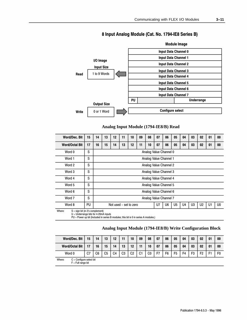
8 Input Analog Module (Cat. No. 1794�IE8 Series B)
Module Image
I/O Image
Input Data Channel 0
Input Data Channel 1
Input Data Channel 2
Input Data Channel 3
Input Data Channel 4
Input Data Channel 5
Input Data Channel 6
Input Data Channel 7
Underrange
Configure select
Input Size
Output Size
0 or 1 Word
1 to 9 Words
PU
Read
Write
Analog Input Module (1794-IE8/B) Read
Word/Dec. Bit 15 14 13 12 11 10 09 08 07 06 05 04 03 02 01 00
Word/Octal Bit 17 16 15 14 13 12 11 10 07 06 05 04 03 02 01 00
Word 0 S Analog Value Channel 0
Word 1 S Analog Value Channel 1
Word 2 S Analog Value Channel 2
Word 3 S Analog Value Channel 3
Word 4 S Analog Value Channel 4
Word 5 S Analog Value Channel 5
Word 6 S Analog Value Channel 6
Word 7 S Analog Value Channel 7
Word 8 PU Not used - set to zero U7 U6 U5 U4 U3 U2 U1 U0
Where: S = sign bit (in 2's complement)U = Underrange bits for 4�20mA inputsPU = Power up bit (Included in series B modules; this bit is 0 in series A modules.)
Analog Input Module (1794-IE8/B) Write Configuration Block
Word/Dec. Bit 15 14 13 12 11 10 09 08 07 06 05 04 03 02 01 00
Word/Octal Bit 17 16 15 14 13 12 11 10 07 06 05 04 03 02 01 00
Word 0 C7 C6 C5 C4 C3 C2 C1 C0 F7 F6 F5 F4 F3 F2 F1 F0
Where: C = Configure select bitF = Full range bit

3–12 Communicating with FLEX I/O Modules
Publication 1794�6.5.3 - May 1996
Range Selection Bits for the 1794-IE8/B Analog Input Module
Channel No. Channel 0 Channel 1 Channel 2 Channel 3 Channel 4 Channel 5 Channel 6 Channel 7
F0 C0 F1 C1 F2 C2 F3 C3 F4 C4 F5 C5 F6 C6 F7 C7
Decimal Bits(Octal Bits)
0008
(10)01
09(11)
0210
(12)03
11(13)
0412
(14)05
13(15)
0614
(16)07
15(17)
0-10V dc/0-20mA 1 0 1 0 1 0 1 0 1 0 1 0 1 0 1 0
4-20mA 0 1 0 1 0 1 0 1 0 1 0 1 0 1 0 1
�10 to +10V dc 1 1 1 1 1 1 1 1 1 1 1 1 1 1 1 1
Off1 0 0 0 0 0 0 0 0 0 0 0 0 0 0 0 0
C = Configure select bit
F = Full range bit1 When configured to off, individual channels will return 0000H on Series B modules, and 4 to 20mA on Series A modules.
4 Output Analog Module (Cat. No. 1794�OE4 Series B)
Module ImageI/O Image
Analog Data Channel 0
Analog Data Channel 1
Analog Data Channel 2
Analog Data Channel 3
Not used
Not used Not used
Not used
Not used
Not used
Not used
Not used
Diagnostics
Config. Select Full Range
Input Size
Output Size
0 or 1 Word
1 or 14 Words
Read
Write
MC
PU
Safe State Value - Channel 0
Safe State Value - Channel 1
Safe State Value - Channel 2
Safe State Value - Channel 3
Analog Output Module (1794-OE4) Read
Word/Dec. Bit 15 14 13 12 11 10 09 08 07 06 05 04 03 02 01 00
Word/Octal Bit 17 16 15 14 13 12 11 10 07 06 05 04 03 02 01 00
Read Word 0 PU Not used - set to 0 W3 W2 W1 W0
Where: W = Diagnostic bits for current output - wire broken or load resistance high. (4�20mA mode only. Not used on voltage outputs.)PU = Power up bit (Included in series B modules; this bit is 0 in series A modules.)

3–13Communicating with FLEX I/O Modules
Publication 1794�6.5.3 - May 1996
Analog Output Module (1794-OE4/B) WriteConfiguration Block
Word/Dec. Bit 15 14 13 12 11 10 09 08 07 06 05 04 03 02 01 00
Word/Octal Bit 17 16 15 14 13 12 11 10 07 06 05 04 03 02 01 00
Write Word 0 S Analog Data - Channel 0
Word 1 S Analog Data - Channel 1
Word 2 S Analog Data - Channel 2
Word 3 S Analog Data - Channel 3
Word 4 0 Not used - set to 0 M3 M2 M1 M0
Word 5 0 Not used - set to 0 C3 C2 C1 C0 Not used - set to 0 F3 F2 F1 F0
Word 6 thru 9 Not used - set to 0
Word 10 S Safe State Value - Channel 0
Word 11 S Safe State Value - Channel 1
Word 12 S Safe State Value - Channel 2
Word 13 S Safe State Value - Channel 3
Where: S = Sign bit (in 2's complement)M = Multiplex controlC = Configure select bitF = Full range bit
Range Selection Bits for the 1794-OE4/B Analog Output Module(Word 5)
Channel No. Channel 0 Channel 1 Channel 2 Channel 3
F0 C0 F1 C1 F2 C2 F3 C3
Decimal Bits (Octal Bits) 00 08 (10) 01 09 (11) 02 10 (12) 03 11 (13)
4-20mA 0 1 0 1 0 1 0 1
0-10V dc/0-20mA 1 0 1 0 1 0 1 0
�10 to +10V dc 1 1 1 1 1 1 1 1
Off1 0 0 0 0 0 0 0 0
C = Configure select bit
F = Full range bit1 When configured to off, individual channels will send 0V or 0mA on Series B modules. On Series A modules, 2V or 4mA is output
until the module is configured.
3–14 Communicating with FLEX I/O Modules
Publication 1794�6.5.3 - May 1996
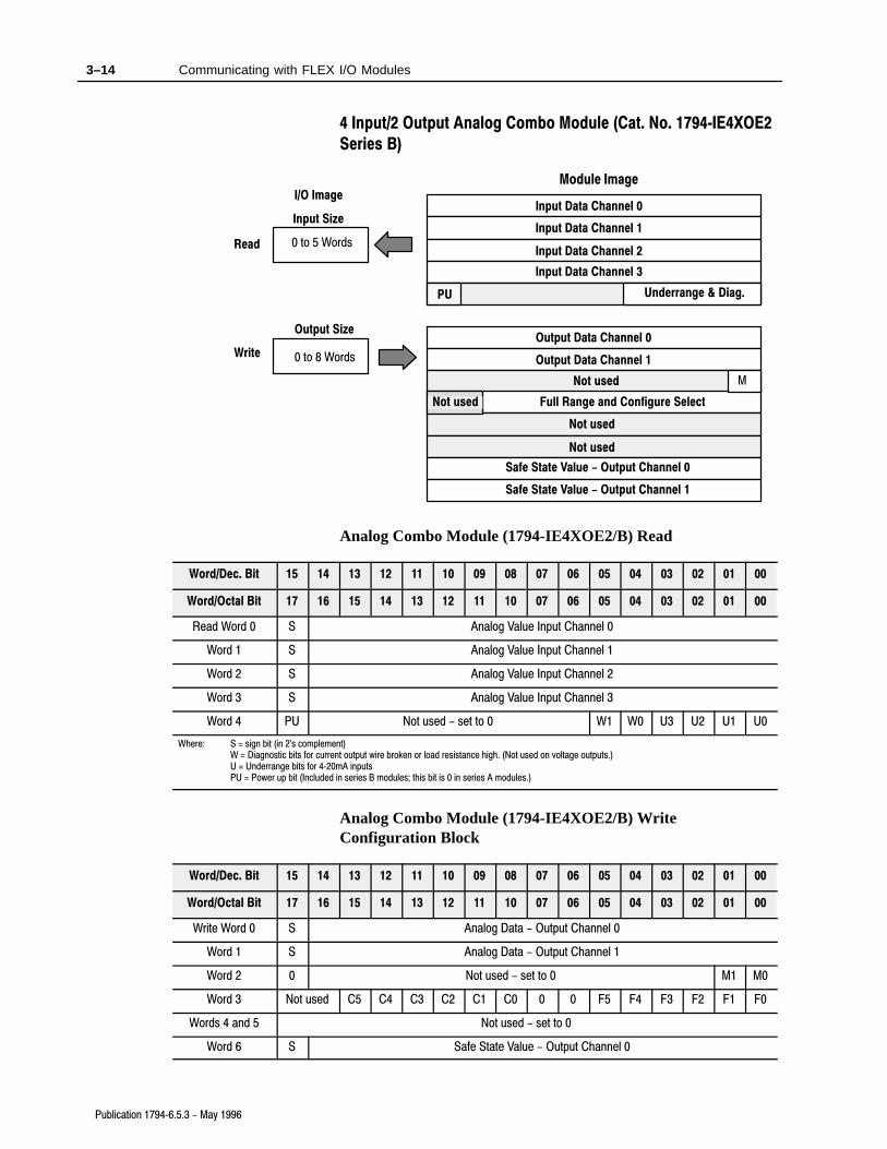
4 Input/2 Output Analog Combo Module (Cat. No. 1794�IE4XOE2
Series B)
Module ImageI/O Image
Input Data Channel 0
Input Data Channel 1
Input Data Channel 2
Input Data Channel 3
Output Data Channel 0
Output Data Channel 1
Underrange & Diag.
Not used
Not used
Not used Full Range and Configure Select
Not used
Input Size
Output Size
0 to 8 Words
0 to 5 WordsRead
Write
M
PU
Safe State Value - Output Channel 0
Safe State Value - Output Channel 1
Analog Combo Module (1794-IE4XOE2/B) Read
Word/Dec. Bit 15 14 13 12 11 10 09 08 07 06 05 04 03 02 01 00
Word/Octal Bit 17 16 15 14 13 12 11 10 07 06 05 04 03 02 01 00
Read Word 0 S Analog Value Input Channel 0
Word 1 S Analog Value Input Channel 1
Word 2 S Analog Value Input Channel 2
Word 3 S Analog Value Input Channel 3
Word 4 PU Not used - set to 0 W1 W0 U3 U2 U1 U0
Where: S = sign bit (in 2's complement)W = Diagnostic bits for current output wire broken or load resistance high. (Not used on voltage outputs.)U = Underrange bits for 4�20mA inputsPU = Power up bit (Included in series B modules; this bit is 0 in series A modules.)
Analog Combo Module (1794-IE4XOE2/B) WriteConfiguration Block
Word/Dec. Bit 15 14 13 12 11 10 09 08 07 06 05 04 03 02 01 00
Word/Octal Bit 17 16 15 14 13 12 11 10 07 06 05 04 03 02 01 00
Write Word 0 S Analog Data - Output Channel 0
Word 1 S Analog Data - Output Channel 1
Word 2 0 Not used - set to 0 M1 M0
Word 3 Not used C5 C4 C3 C2 C1 C0 0 0 F5 F4 F3 F2 F1 F0
Words 4 and 5 Not used - set to 0
Word 6 S Safe State Value - Output Channel 0

3–15Communicating with FLEX I/O Modules
Publication 1794�6.5.3 - May 1996
00010203040506070809101112131415Word/Dec. Bit
00010203040506071011121314151617Word/Octal Bit
Word 7 S Safe State Value - Output Channel 1
Where: S = Sign bit (in 2's complement)M = Multiplex controlC = Configure select bitF = Full range bit
Range Selection Bits for the 1794-IE4XOE2/B AnalogCombo Module
Channel No. InputChannel 0
InputChannel 1
InputChannel 2
InputChannel 3
OutputChannel 0
OutputChannel 1
F0 C0 F1 C1 F2 C2 F3 C3 F4 C4 F5 C5
Decimal Bits(Octal Bits)
0008
(10)01
09(11)
0210
(12)03
11(13)
0412
(14)05
13(15)
4-20mA 0 1 0 1 0 1 0 1 0 1 0 1
0-10V dc/0-20mA 1 0 1 0 1 0 1 0 1 0 1 0
�10 to +10V dc 1 1 1 1 1 1 1 1 1 1 1 1
Off1 0 0 0 0 0 0 0 0 0 0 0 0
C = Configure select bitF = Full range bit1 When configured to off, individual channels will send 0V or 0mA on Series B modules. On Series A modules, 2V or 4mA is output
until the module is configured.

3–16 Communicating with FLEX I/O Modules
Publication 1794�6.5.3 - May 1996
RTD Input Module (1794�IR8) Image Table Mapping
Module Image
I/O Image
Input Data Channel 0
Input Data Channel 1
Input Data Channel 2
Input Data Channel 3
Input Data Channel 4
Input Data Channel 5
Input Data Channel 6
Input Data Channel 7
Underrange
Calibration Mask
RTD Type
Input Size
Output Size
0 to 3 Words
1 to 11 Words
Reserved
Overrange
Calibration Status
RTD Type
Configuration
Read
Write
RTD Analog Input Module (1794-IR8) Read Words
Decimal Bit 15 14 13 12 11 10 09 08 07 06 05 04 03 02 01 00
Octal Bit 17 16 15 14 13 12 11 10 07 06 05 04 03 02 01 00
Read Word 0 Reserved
1 Channel 0 Input Data
2 Channel 1 Input Data
3 Channel 2 Input Data
4 Channel 3 Input Data
5 Channel 4 Input Data
6 Channel 5 Input Data
7 Channel 6 Input Data
8 Channel 7 Input Data
9 Overrange Bits Underrange Bits
10 0 0 0 0 0BadCal
CalDone
CalRange
0DiagnosticStatus Bits
PwrUp
Reserved 0 0
3–17Communicating with FLEX I/O Modules
Publication 1794�6.5.3 - May 1996
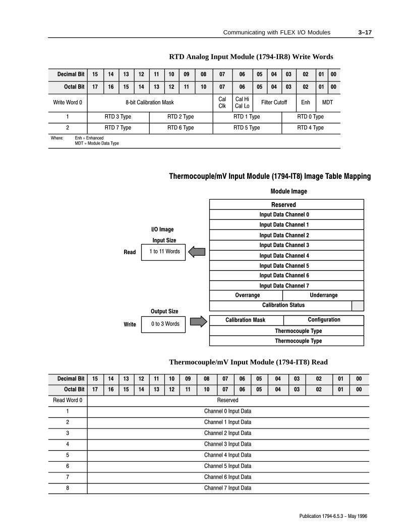
RTD Analog Input Module (1794-IR8) Write Words
Decimal Bit 15 14 13 12 11 10 09 08 07 06 05 04 03 02 01 00
Octal Bit 17 16 15 14 13 12 11 10 07 06 05 04 03 02 01 00
Write Word 0 8�bit Calibration MaskCalClk
Cal HiCal Lo
Filter Cutoff Enh MDT
1 RTD 3 Type RTD 2 Type RTD 1 Type RTD 0 Type
2 RTD 7 Type RTD 6 Type RTD 5 Type RTD 4 Type
Where: Enh = EnhancedMDT = Module Data Type
Thermocouple/mV Input Module (1794�IT8) Image Table Mapping
Module Image
I/O Image
Input Data Channel 0
Input Data Channel 1
Input Data Channel 2
Input Data Channel 3
Input Data Channel 4
Input Data Channel 5
Input Data Channel 6
Input Data Channel 7
Underrange
Calibration Mask
Thermocouple Type
Input Size
Output Size
0 to 3 Words
1 to 11 Words
Reserved
Overrange
Calibration Status
Thermocouple Type
Configuration
Read
Write
Thermocouple/mV Input Module (1794-IT8) Read
Decimal Bit 15 14 13 12 11 10 09 08 07 06 05 04 03 02 01 00
Octal Bit 17 16 15 14 13 12 11 10 07 06 05 04 03 02 01 00
Read Word 0 Reserved
1 Channel 0 Input Data
2 Channel 1 Input Data
3 Channel 2 Input Data
4 Channel 3 Input Data
5 Channel 4 Input Data
6 Channel 5 Input Data
7 Channel 6 Input Data
8 Channel 7 Input Data

3–18 Communicating with FLEX I/O Modules
Publication 1794�6.5.3 - May 1996
00010203040506070809101112131415Decimal Bit
00010203040506071011121314151617Octal Bit
9 Overrange Bits Underrange Bits
10 0 0 0 0 0BadCal
CalDone
CalRange
0 Diagnostic StatusPwrUp
BadStructure
CJCover
CJCUnder
Thermocouple/mV Input Module (1794-IT8) Write
Dec. Bit 15 14 13 12 11 10 09 08 07 06 05 04 03 02 01 00
Octal Bit 17 16 15 14 13 12 11 10 07 06 05 04 03 02 01 00
Write Word 0 8�Bit Calibration MaskCalClk
Cal hiCal lo
Filter Cutoff FDF Data Type
1 Thermocouple 3 Type Thermocouple 2 Type Thermocouple 1 Type Thermocouple 0 Type
2 Thermocouple 7 Type Thermocouple 6 Type Thermocouple 5 Type Thermocouple 4 Type
Where: FDF = fixed digital filter bit
Most reset commands are issued by the processor when it is placedin the PROG mode. However, the processor automatically issues aspecial command to any rack declared faulted regardless of theprocessor mode.
When this special command is received by the faulted remote I/Oadapter, and processor restart lockout (PRL) has not been selected,the adapter will:
• continue to read output image data from the link, and queue blocktransfers if MCBs are detected
• reset all bits in the output words of discrete modules
• reset all bits in the write words of analog modules up to but notincluding the write words of the safe state values
• assigns safe state values to outputs of analog modules
• issue a reply command
If processor restart lockout (PRL) has been selected, the adapter doesnot update data, does not issue a reply command, and does not clearthe fault.
In this chapter, you learned how to address your I/O, how todetermine rack size, and how the modules are mapped
Operating Modes
Chapter Summary
Reset Switch
Allen�Bradley
24 VDCPOWER SUPPLY
RIO ADAPTER1794-ASB
ADAPTER
ACTIVE FAULT
LOCAL
FAULT
Chapter 4
Publication 1794�6.5.3 - May 1996
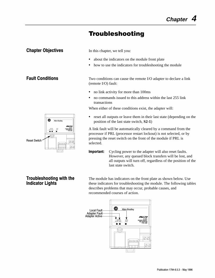
Troubleshooting
In this chapter, we tell you:
• about the indicators on the module front plate
• how to use the indicators for troubleshooting the module
Two conditions can cause the remote I/O adapter to declare a link(remote I/O) fault:
• no link activity for more than 100ms
• no commands issued to this address within the last 255 linktransactions
When either of these conditions exist, the adapter will:
• reset all outputs or leave them in their last state (depending on theposition of the last state switch, S2-1)
A link fault will be automatically cleared by a command from theprocessor if PRL (processor restart lockout) is not selected, or bypressing the reset switch on the front of the module if PRL isselected.
Important: Cycling power to the adapter will also reset faults.However, any queued block transfers will be lost, andall outputs will turn off, regardless of the position of thelast state switch.
The module has indicators on the front plate as shown below. Usethese indicators for troubleshooting the module. The following tablesdescribes problems that may occur, probable causes, andrecommended courses of action.
Adapter FaultLocal Fault
Adapter Active
Allen�Bradley
24 VDCPOWER SUPPLY
RIO ADAPTER1794-ASB
ADAPTER
ACTIVE FAULT
LOCAL
FAULT
Chapter Objectives
Fault Conditions
Troubleshooting with theIndicator Lights
Adapter Fault
Local Fault Allen�Bradley
24 VDCPOWER SUPPLY
RIO ADAPTER1794-ASB
ADAPTERACTIVE FAULT
LOCALFAULT
Adapter Active
4–2 Troubleshooting
Publication 1794�6.5.3 - May 1996
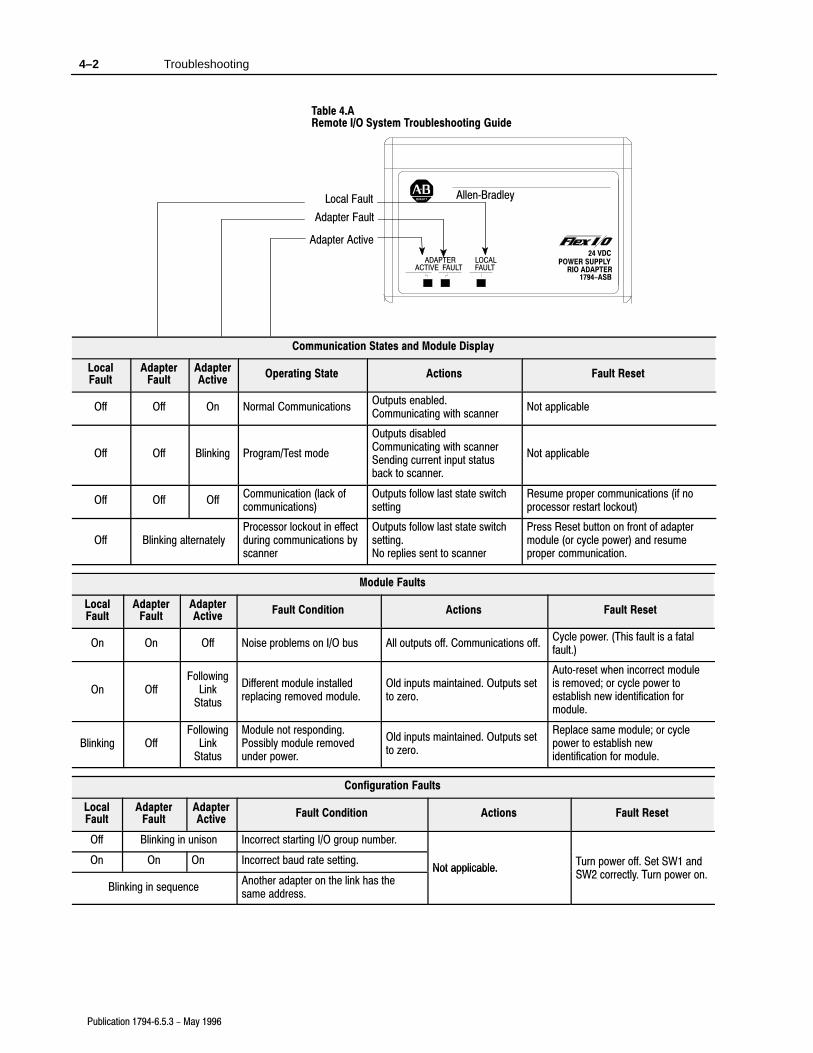
Table 4.ARemote I/O System Troubleshooting Guide
Communication States and Module Display
LocalFault
AdapterFault
AdapterActive
Operating State Actions Fault Reset
Off Off On Normal CommunicationsOutputs enabled.Communicating with scanner
Not applicable
Off Off Blinking Program/Test mode
Outputs disabledCommunicating with scannerSending current input statusback to scanner.
Not applicable
Off Off OffCommunication (lack ofcommunications)
Outputs follow last state switchsetting
Resume proper communications (if noprocessor restart lockout)
Off Blinking alternatelyProcessor lockout in effectduring communications byscanner
Outputs follow last state switchsetting.No replies sent to scanner
Press Reset button on front of adaptermodule (or cycle power) and resumeproper communication.
Module Faults
LocalFault
AdapterFault
AdapterActive
Fault Condition Actions Fault Reset
On On Off Noise problems on I/O bus All outputs off. Communications off.Cycle power. (This fault is a fatalfault.)
On OffFollowing
LinkStatus
Different module installedreplacing removed module.
Old inputs maintained. Outputs setto zero.
Auto�reset when incorrect moduleis removed; or cycle power toestablish new identification formodule.
Blinking OffFollowing
LinkStatus
Module not responding.Possibly module removedunder power.
Old inputs maintained. Outputs setto zero.
Replace same module; or cyclepower to establish newidentification for module.
Configuration Faults
LocalFault
AdapterFault
AdapterActive
Fault Condition Actions Fault Reset
Off Blinking in unison Incorrect starting I/O group number.
On On On Incorrect baud rate setting.Not applicable.
Turn power off. Set SW1 andSW2 tl T
Blinking in sequenceAnother adapter on the link has thesame address.
Not applicable.p
SW2 correctly. Turn power on.

4–3Troubleshooting
Publication 1794�6.5.3 - May 1996
Additional Faults and Module Displays
LocalFault
AdapterFault
AdapterActive
Fault Condition Actions Fault Reset
Random Access Memory fault.Reset outputs. Stopcommunicating on remote I/Olink.
Cycle power. (This may notcorrect fault.)
Off On OffRead Only Memory fault (onpowerup only).
Outputs remain reset.Communication never starts.
correct fault.) If this does not correct the fault,replace the module with a knowngood module and return the bad
Internal watchdog timer timedout.
Try to reset outputs. Stopscommunicating on the remote I/Olink.
good module, and return the badmodule to the factory for repair.
In this chapter you learned how to use the indicators on the front ofthe module to troubleshoot your module.
Chapter Summary

Appendix A
Publication 1794�6.5.3 - May 1996
Specifications
1794�ASB Remote I/O Adapter
I/O Capacity 8 modules
Input Voltage Rating 24V dc nominal
Input Voltage Range 19.2V to 31.2V dc (includes 5% ac ripple)
Communication Rate 57.6k bps115.2k bps230.4k bps
Indicators Adapter Active - greenAdapter fault - redLocal fault - red
Flexbus Output Current 640mA maximum
Isolation Voltage 100% tested at 850V dc for 1s between user powerand flexbus
Power Consumption 450mA maximum from external 24V supply
Power Dissipation 4.6W maximum @ 31.2V dc
Thermal Dissipation 15.7 BTU/hr @ 31.2V dc
Environmental ConditionsOperational TemperatureStorage TemperatureRelative HumidityShock Operating
Non�operatingVibration
0 to 55oC (32 to 131oF)-40 to 85oC (-40 to 185oF)5 to 95% noncondensing30 g peak acceleration, 11(+1)ms pulse width50 g peak acceleration, 11(+1)ms pulse widthTested 5 g @ 10-500Hz per IEC 68�2�6
Remote I/O Cable Belden 9463 or equivalent as specified inpublication ICCG�2.2
Power ConductorsWire Size
Category
12 gauge (4mm2) stranded maximum3/64 inch (1.2mm) insulation max.21
Remote I/O Connector Plug Part Number 942029-03
Agency Certification(when product or packaging ismarked)
• CSA certified
• CSA Class I, Division 2Groups A, B, C, D certified
• UL listed
• CE marked for all applicable directives
1 Use this conductor category information for planning conductor routing. Refer to publication 1770�4.1, �Industrial
Automation Wiring and Grounding Guidelines for Noise Immunity."

Symbols
**Empty**, P-2, 1-4, 2-10, 3-1, 3-2, 3-4, 3-16, 4-4, 4-1
A
adapter switch settings, 2-6
addressing, I/O groups, 3-2
audience, P-1
B
block transferread, 1-2write, 1-2
block transfer read1794�IE4XOE2, 3-141794�IE8, 3-111794�IR8, 3-161794�IT8, 3-171794�OE4, 3-12
block transfer write1794�IE4XOE2, 3-141794�IE8, 3-111794�IR8, 3-171794�IT8, 3-181794�OE4, 3-12configuration block
1794�IE4XOE2, 3-141794�IE8, 3-111794�IR8, 3-171794�IT8, 3-181794�OE4, 3-13
C
components, hardware, 1-3
configuration block, block transfer write, 3-11, 3-13
connecting wiring, 2-5
D
defining racks in Flex I/O, 3-3
delay times1794�IA8, 3-81794�IB16, 3-51794�IB8S, 3-7
diagnostic indicators, 1-3
I
image table memory map1794�IB16, 3-51794�IA8, 3-81794�IB10XOB6, 3-71794�IB8S, 3-61794�OA8, 3-91794�OB16, 3-61794�OW8, 3-9
indicators, 4-1
input delay1794�IA8, 3-81794�IB16, 3-51794�IB8S, 3-7
M
mapping1794�IR, 3-161794�IT8, 3-17
mapping data1794�IA8, 3-81794�IB16, 3-51794�IB8S, 3-61794�OB16, 3-61794�OW8, 3-91794-IB10XOB6, 3-71794�OA8, 3-9analog modules, 3-10discrete I/O modules, 3-4
mounting on a DIN rail, 2-2
mounting on a wall or panel, 2-3
P
power requirements, 2-2
R
rack definition, 3-3
rack image, 3-2
range selection1794�IE4XOE2, 3-151794�IE8, 3-121794�OE4, 3-13
Index
IndexI–2
remote I/O cable, connecting the wiring, 2-5
RTD analog input mapping, 1794�IR, 3-16
S
safe state values, 3-18
specifications, A-1
switch settings, 2-6
T
thermocouple input mapping, 1794�IT8, 3-17
troubleshooting guide, 4-2
troubleshooting indicators, 4-1

Allen�BradleyPublication Problem ReportIf you find a problem with our documentation, please complete and return this form.
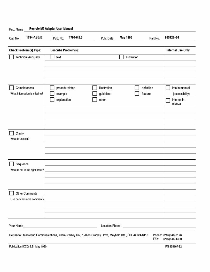
Pub. Name
Cat. No. Pub. No. Pub. Date Part No.
Check Problem(s) Type: Describe Problem(s): Internal Use Only
procedure/step
example
explanation
illustration
guideline
other
definition
feature
info in manual
(accessibility)
info not inmanual
text illustrationTechnical Accuracy
Completeness
What information is missing?
Clarity
Sequence
What is not in the right order?
What is unclear?
Other Comments
Use back for more comments.
Your Name Location/Phone
Return to: Marketing Communications, Allen�Bradley Co., 1 Allen�Bradley Drive, Mayfield Hts., OH 44124�6118 Phone: (216)646�3176FAX: (216)646�4320
Publication ICCG�5.21�May 1990 PN 955107�82
Remote I/O Adapter User Manual
1794�ASB/B 1794�6.5.3 955122-64May 1996

Other Comments
PLEASE FOLD HERE
PLE
AS
E R
EM
OV
E
NO POSTAGE NECESSARY
IF MAILED IN THE
UNITED STATES
BUSINESS REPLY MAILFIRST-CLASS MAIL PERMIT NO. 18235 CLEVELAND OH
POSTAGE WILL BE PAID BY THE ADDRESSEE
TECHNICAL COMMUNICATION1 ALLEN BRADLEY DRMAYFIELD HEIGHTS OH 44124-9705

Support Services
Publication 1794�6.5.3 - May 1996
At Allen-Bradley, customer service means experiencedrepresentatives at Customer Support Centers in key cities throughoutthe world for sales service and support. Our value-added servicesinclude:
Technical Support
• SupportPlus programs
• telephone support and 24-hour emergency hotline
• software and documentation updates
• technical subscription services
Engineering and Field Services
• application engineering assistance
• integration and start-up assistance
• field service
• maintenance support
Technical Training
• lecture and lab courses
• self-paced computer and video-based training
• job aids and workstations
• training needs analysis
Repair and Exchange Services
• your only “authorized” source
• current revisions and enhancements
• worldwide exchange inventory
• local support
Support Services

Publication 1794�6.5.3 - May 1996
Allen�Bradley, a Rockwell Automation Business, has been helping its customers improveproductivity and quality for more than 90 years. We design, manufacture and support a broadrange of automation products worldwide. They include logic processors, power and motioncontrol devices, operator interfaces, sensors and a variety of software. Rockwell is one of theworld's leading technology companies.
Worldwide representation.
Argentina • Australia • Austria • Bahrain • Belgium • Brazil • Bulgaria • Canada • Chile • China, PRC • Colombia • Costa Rica • Croatia • Cyprus • Czech Republic •Denmark • Ecuador • Egypt • El Salvador • Finland • France • Germany • Greece • Guatemala • Honduras • Hong Kong • Hungary • Iceland • India • Indonesia •
Ireland • Israel • Italy • Jamaica • Japan • Jordan • Korea • Kuwait • Lebanon • Malaysia • Mexico • Netherlands • New Zealand • Norway • Pakistan • Peru •Philippines • Poland • Portugal • Puerto Rico • Qatar • Romania • Russia-CIS • Saudi Arabia • Singapore • Slovakia • Slovenia • South Africa, Republic • Spain •Sweden • Switzerland • Taiwan • Thailand • Turkey • United Arab Emirates • United Kingdom • United States • Uruguay • Venezuela • Yugoslavia
Allen�Bradley Headquarters, 1201 South Second Street, Milwaukee, WI 53204 USA, Tel: (1) 414 382�2000 Fax: (1) 414 382�4444
Publication 1794�6.5.3 - May 1996Supersedes Publication 1794�6.5.3 - February 1995
PN955122-64Copyright 1996 Allen�Bradley Company, Inc. Printed in USA