removal and recovery of methyl ethyl ketone (mek) vapor ... · (hqusace) under project...
TRANSCRIPT

:v:i 20000128 015 US Army Corps of Engineers Engineer Research and Development Center
CERL Technical Report 99/90 November 1999
Removal and Recovery of Methyl Ethyl Ketone (MEK) Vapor Emissions by Carbon Fiber Adsorber-Cryogenic Condenser
Mark J. Rood
Patrick D. Sullivan
Mehrdad Lordgooei
Shaoying Qi
K. James Hay
House Air ir r*ft- MFC—I
Filter
Recycle Loop
Bubblers
Humidifier
ooo ooo
Regen Sam pit
Nitrogen
. Effluent ooo ooo
Refrigerated Bath" £^
The Clean Air Act Amendments of 1990 mandate the reduction of emissions of hazardous air pollutants (HAP). Activated carbon fiber-cloth (ACFC) offers promise as a superior adsorbent to remove and recover organic HAP from gas streams. This study designed, built, and tested a second-generation system with an improved adsorber using methyl ethyl ketone (MEK) as the organic pollutant. Total flow rate of the bench-scale system was 5 Lpm with the gas stream containing 1000 ppmv MEK. Breakthrough times ranged between 11.9 and 12.9 hr. Throughput ratios of 86.9 percent were achieved. Electrothermal regeneration times were approximately 1 hr at 100W.
It was shown that increasing the adsorption bed's dry-bulb temperature by 10 °C can cut adverse effects of treating high humidity gas streams in half. The system was automated to demonstrate continuous MEK adsorption, desorption, condensation, and recovery. Overall removal efficiency during continuous operation was 99.9 percent by mass. The study's preliminary design and cost analysis for a pilot- scale system estimates a cost of $60,000 for a flow rate of 0.5 m7min and a concentration of 1000 ppmv. An economic analysis of a proposed full-scale system shows that a process recovery cost of $2/kg of MEK is achievabjp-.
Approved for public release; distribution is unlimited. WWW.CECER.ARMY.MIL/TECHREPORTS

Inf
US Army Corps of Engineers Engineer Research and Development Center
CERL Technical Report 99/90 November 1999
Removal and Recovery of Methyl Ethyl Ketone (MEK) Vapor Emissions by Carbon Fiber Adsorber-Cryogenic Condenser
Mark J. Rood
Patrick D. Sullivan
Mehrdad Lordgooei Shaoyin^ Qi
K. James Hay
House Air
MFC—|
r-H^-fl
j MFC—)
Filter
Bubblers
Humidifier
ooo 000
Recycle Loop
r^3—*\
Regen Sample
Nitrogen
Effluent
Refrigerated Bath J\^
OOO OOO
The Clean Air Act Amendments of 1990 mandate the reduction of emissions of hazardous air pollutants (HAP). Activated carbon fiber-cloth (ACFC) offers promise as a superior adsorbent to remove and recover organic HAP from gas streams. This study designed, built, and tested a second-generation system with an improved adsorber using methyl ethyl ketone (MEK) as the organic pollutant. Total flow rate of the bench-scale system was 5 Lpm with the gas stream containing 1000 ppmv MEK. Breakthrough times ranged between 11.9 and 12.9 hr. Throughput ratios of 86.9 percent were achieved. Electrothermal regeneration times were approximately 1 hr at 100W.
It was shown that increasing the adsorption bed's dry-bulb temperature by 10 °C can cut adverse effects of treating high humidity gas streams in half. The system was automated to demonstrate continuous MEK adsorption, desorption, condensation, and recovery. Overall removal efficiency during continuous operation was 99.9 percent by mass. The study's preliminary design and cost analysis for a pilot- scale system estimates a cost of $60,000 for a flow rate of 0.5 m7min and a concentration of 1000 ppmv. An economic analysis of a proposed full-scale system shows that a process recovery cost of $2/kg of MEK is achievable.
Approved for public release; distribution is unlimited. WWW.CECER.ARMY.MIL/TECHREPORTS

CERL TR 99/90
Foreword
This research was performed for Headquarters, U.S. Army Corps of Engineers (HQUSACE) under Project 4A162720DO48, "Industrial Operations Pollution Control Technology," Work Unit T88, "Strategies for Minimizing Hazardous Air Pollutants from Industrial Operations."
The research was performed by the Environmental Processes Branch (CN-E) of the Installations Division (CN), U.S. Army Construction Engineering Research Laboratory (CERL). The CERL principal investigator was Dr. K. James Hay. During the time of this research, Dr. Shaoying Qi was an IPA contractor through the University of Cincinnati. Dr. Mark J. Rood is a Professor with the Depart- ment of Civil Engineering at the University of Illinois, Urbana-Champaign. Pat- rick D. Sullivan and Mehrdad Lordgooei are also associated with the University of Illinois at Urbana. L. Jerome Benson is Chief, CEERD-CN-E; Dr. John T Bandy is Chief, CEERD-CN; and Gary W. Schanche is the responsible Technical Director, CEERD-TD. The CERL technical editor was William J. Wolfe, Informa- tion Technology Laboratory.
The Director of CERL is Dr. Michael J. O'Connor.
DISCLAIMER
The contents of this report are not to be used for advertising, publication, or promotional purposes. Citation of trade names does not constitute an official endorsement or approval of the use of such commercial products. All product names and trademarks cited are the property of their respective owners.
The findings of this report are not to be construed as an official Department of the Army position unless so designated by other authorized documents.
DESTROY THIS REPORT WHEN IT IS NO LONGER NEEDED. DO NOT RETURN IT TO THE ORIGINATOR.

CERL TR 99/90
Contents
Foreword 2
List of Figures and Tables 4
1 Introduction 5
Background 5
Objective 6
Approach .6
Mode of Technology Transfer 7
2 Experimental System 8
Overall System Design 8
Simulated Gas Generation 9
Adsorber 9
Condensation Unit 12
Analytical Measurement Instruments 12
Data Acquisition and Control System (DACS) 12
Theory and Experimental Procedures 13
3 Experimental Results and Discussion 17
Resistivity Results 17
Adsorption Experimental Results 18
Experimental Desorption Results 22
Experimental Condensation Results 24
Development and Operation of the Automated ACFC Adsorption/Desorption/Cryogenic Condensation System 24
4 Pilot Design and Cost Estimates 30
5 Summary and Conclusions 35
References 36
Distribution 38
Report Documentation Page 39

CERL TR 99/90
List of Figures and Tables
Figures
1 Bench-scale ACFC adsorption-cryogenic vapor'recovery system 8
2 The first and second generation adsorbers 10
3 Length/width ratio vs. resistance for three ACFC lots 17
4 Comparison of the pressure drop through the first and second generation adsorbers 19
5 Comparison of breakthrough curves of the first and second generation adsorbers 19
6 Replicate breakthrough curves for the new adsorber 20
7 Breakthrough curves for different operating conditions. (The curve for 4360 ppmv is normalized with 100% being equal to 1000 ppmv.) 21
8 Comparison of adsorption capacities 22
9 Electro-thermal regeneration curves with voltage under manual control 23
10 Electro-thermal regeneration curve with voltage under PID control 23
11 Condenser concentration and temperature vs. time for 2 Lpm flow 25
12 Condenser effluent concentration vs. temperature 25
13 The automated ACFC adsorption/desorption/cryogenic system 27
14 Adsorber effluent concentration and temperature vs. time for continuous operation 28
15 Concept drawing of pilot scale system 31
Tables
1 Identification and properties of the ACFC used for the specified experiments 11
2 Resistances of the assembled beds of ACFC, LotC 18
3 Design parameters for bench and pilot systems 31
4 Pilot-scale system cost estimate 32
5 Annual operating cost and cost per unit mass MEK recovered for full-scale system 34
CERLTRSSJ90
1 Introduction
Background
Abatement of Hazardous Air Pollutants (HAPs) has become an important issue for the U.S. Army. Many of the top chemicals on the Army Toxic Release Inven- tory (TRI) are volatile organic compound (VOC) HAP. Recently, combined with VOC emission control, HAP control became the number three ranked Army User Compliance Requirement, due to current and forthcoming air toxic regulations. The Army needs cost effective technologies to bring its facilities into compliance with these regulations. The Activated carbon fiber-cloth (ACFC) Adsorber and Cryogenic Condenser system is a promising new technology for the control and recycling of organic HAP such as methyl ethyl ketone (MEK) and chlorinated or- ganics. This research continues the work described by Rood et al. (1998).
ACFC possesses unique physical and chemical properties that make it an ideal adsorbent for removal of gas-phase VOCs from gas streams. ACFC can have N2- BET surface areas > 2000 m2/g compared to 1000 m2/g for typical activated car- bon adsorbents. The precursor of ACFC is a phenolic resin, which is free from impurities such as ash. Individual ACFC fibers are ~10 um in diameter, which provide excellent kinetic properties. Because of its chemical and physical prop- erties, ACFC readily desorbs using electro-thermal treatment. ACFC is micro- porous and has a narrow distribution of pore sizes due to the homogenous nature of the feedstock (Hayes 1981). These properties give ACFC high adsorption ca- pacities for many organic HAPs.
For example, ACFC properties are superior to conventional activated carbon ad- sorbents in the adsorption of aldehydes and ketones, and ACFC is better suited for use in small chlorinated organic solvent recovery systems. Conventional activated carbon beds are known to be susceptible to bed fires (Cheremisinoff and Cheremisinoff 1993). However, CERL researchers have not observed such behavior with ACFC adsorbing MEK from air. It is possible that ACFC has not exhibited bed fires due to ACFC's lack of impurities (i.e., ash) that are observed in conventional activated carbons. The ash may catalyze exothermic reactions, which may lead to combustion. ACFC's ability to inhibit bed fires may also be due to its physical woven form, which minimizes the formation of localized hot spots. Moreover, ACFC systems that recover chlorinated solvents can

CERL TR 99/90
incorporate electro-thermal desorption without the need for an inert carrier gas. This allows a compact, energy-efficient chlorinated solvent recovery system to be constructed with electricity as the only utility required to regenerate the adsorbent.
ACFC offers the same advantages for pollution abatement as other recovery pro- cesses. ACFC adsorption and recovery does not contribute to the formation of greenhouse gases, as do methods using combustion. Capture and recovery re- sults in the lower total emissions than other currently acceptable methods used to comply with 1990 Clean Air Act Amendments (CAAAs), such as the use of low- VOC containing substitutes (USEPA 1990). Capture and recovery methods will become more important in the future as Maximum Available Control Technology (MACT) standards for 188 HAPs are developed by the U.S. Environmental Pro- tection Agency (USEPA).
MEK was selected as the target compound for this study because it is an impor- tant and widely used solvent, and also because it is designated as one of the 188 regulated HAPs in Title III of the 1990 CAAAs, due to its impact on human health and the environment. In 1995, MEK ranked sixth on the list of HAPs emitted into the environment, at nearly 27 x 106 Kg/yr for the United States (USEPA 1998).
Objective
The overall objective of the research was to complete a bench-scale investigation with system integration and optimization to obtain design parameters for a pilot- scale system. The pilot-scale system is to consist of an ACFC adsorber-cryogenic condenser for removal and recovery of MEK or other valuable organic vapors from industrial gas streams.
Approach
1. A new adsorption bed was designed and implemented to minimize deformation of the walls during electro-thermal desorption of the saturated ACFC adsorbent. Details of the new adsorption bed are provided in Chapter 2.
2. Experiments were done with the adsorber at elevated dry-bulb temperature for initially high relative humidity (RH) conditions. The data was used to assess the potential for minimizing the amount of competitive adsorption that can occur by water vapor. Competitive adsorption by water vapor inhibits the adsorption of HAPs and can result in freezing of the water vapor in the condenser during
CERL im. mm
regeneration of the adsorbent. Increasing the dry-bulb temperature decreases RH, resulting in a decrease in ACFC's adsorption capacity for water vapor; this allows penetration of the water vapor during adsorption of the HAPs. The entire bench-scale system was operated on a continuous basis. Operational parameters of the system were adjusted to carefully evaluate the algorithms and set points used for adsorption, electro-thermal desorption, and cryogenic conden- sation of MEK A preliminary design and cost analysis was done for a pilot-scale ACFC adsorber- cryogenic condenser system to be operated at a U.S. Army industrial operation facility.
Mode of Technology Transfer
It is anticipated that the results of this research will be used to develop, test, and implement a pilot-scale ACFC adsorber-cryogenic condenser system to be oper- ated at a U.S. Army industrial operation facility.
CERL TR 99/90
2 Experimental System
Overall System Design
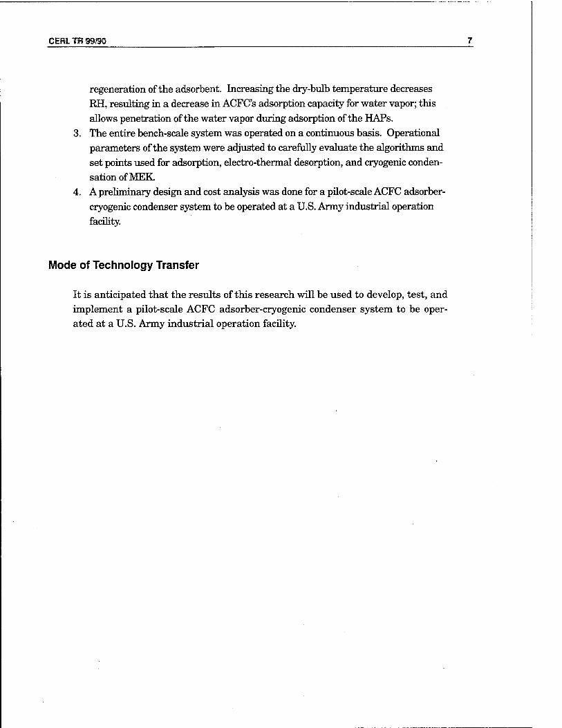
Figure 1 shows the bench-scale ACFC adsorption-cryogenic vapor recovery sys- tem. The integrated system is composed of the gas generator, the ACFC adsor- ber, electro-thermal regeneration power supply, cryogenic condenser, analytical instruments, and a data acquisition and control system (DACS). During MEK adsorption, the MEK-laden air stream passes through the ACFC bed, where the organic material is separated from the carrier gas by adsorption. The exhaust gas from the adsorber is continually analyzed for the concentration of MEK by a flame ionization detector (FID). The exhaust gas is vented to a laboratory hood.
After the ACFC is saturated with MEK, pure N2 gas is passed through the ad- sorption bed and electrical power is supplied to the ACFC to desorb the MEK. The concentration of MEK in the N2 carrier gas is controlled by the electrical power applied to the ACFC and the flow rate of the carrier gas. The N2 gas flow rate is fixed during individual runs, while the electrical power is controlled with a variable voltage power supply, which receives feedback from the FID that sam- ples the gas stream emitted from the regenerating adsorber. The concentrated stream of MEK then passes through tubing immersed in a cryogenic bath where the MEK condenses and is collected in an Erlenmeyer flask.
House Air
MFC—|
Bubblers
Filter
Humidifier
Recycle Loop
Nitrogen
THC/FID ooo o oo
Regen Sample
ooo ooo
Refrigerated Bath ^
Figure 1. Bench-scale ACFC adsorption-cryogenic vapor recovery system.

CERL TR 99/90
Simulated Gas Generation
Figure 1 also shows the gas generation system used to produce MEK in dry air. Compressed air passed through a silica gel desiccant, a fibrous filter, and a granular activated-carbon bed. Combustion air from a compressed gas cylinder for the FID was treated by a separate system (Drierite, Model L68GP). The puri- fied air was branched into two separate streams controlled by two mass flow con- trollers (Tylan, Models FC-260 and FC-280). One air stream passed through two fritted glass bubblers that contained liquid MEK. The bubblers were immersed in a temperature-controlled water bath (Nesläb, Model RTE-110). The air bub- bling through the liquid MEK became saturated. The saturated gas stream was then mixed with the second pure air stream to produce a gas mixture with a de- sired MEK concentration and total flow rate.
A humidifier and hygrometer were added to the system for the 90 percent RH tests. The air stream passing through the bubbler that contained liquid MEK bypassed the humidifier since the gas flow containing MEK was < 1 percent of the total flow. The dilution air stream passed through a custom annular humidi- fier. The humidifier consisted of a (2.54 cm outer diameter) stainless steel tube, with a concentric (1.6 cm diameter) Goretex™ Teflon® membrane on the inside. Deionized water was circulated in the annular space between the stainless steel tube and the membrane. The air stream passed through the inside of the tubu- lar membrane. The membrane permitted transport of water vapor only into the air stream. Heating tape surrounding the outer stainless steel tube controlled the temperature of the liquid water, and thus controlled the partial pressure of water vapor at the membrane's surface.
The RH of the gas stream was determined downstream of the humidifier using a dew-point hygrometer and Type K thermocouple. The RH of the resulting gas streams was controlled by adjusting the voltage applied to the heating tape wrapped around the humidifier.
Flow rates through the mass flow controllers were verified with a flow calibrator (BIOS International, Dry-Cal Model DC-2). The actual concentration of the in- fluent stream was measured using a total hydrocarbon (THC) analyzer with an FID (MSA Inc., Series 8800).
Adsorber
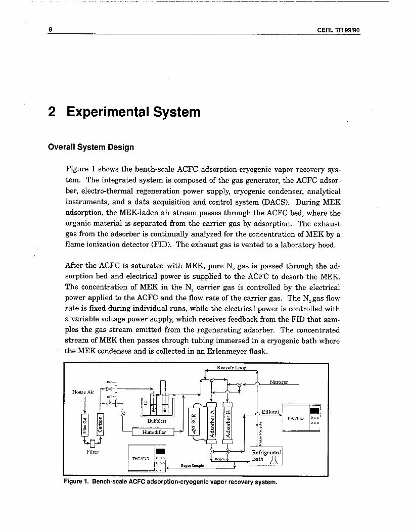
The initial version of the fixed bed of ACFC contained three banks of cloth aligned normal to the flow of the HAP laden gas stream. The ACFC in the bed was supported by 304 stainless steel frames. The side walls of the fixed-bed
10 CERL TR 99/90
adsorber were made of electrical-grade Teflon® sheets. Each bank of ACFC
consisted of 30 pleats of cloth, for a total of 90 pleats. The modules inside the
bed were connected electrically in series. The total mass of ACFC in these three
modules was 19.2 g (Figure 2A). The revised adsorber developed and tested as
part of this research was an annular cartridge-type fixed-bed configuration
(Figure 2B).
The ACFC was rolled into a hollow cylinder resembling a cartridge filter. There
are several advantages to this configuration. First, this configuration keeps the
ACFC out of contact with the sidewalls of the adsorber. This eliminates localized
heating where the ACFC would otherwise be compressed onto the side walls of
the adsorber. Also, heating during electro-thermal desorption of the ACFC
would cause deformation of the adsorber's Teflon® walls. The new configuration
also minimized channeling around the ACFCs. The new configuration required
a relatively small amount of insulating material and was simple and inexpensive
to construct. The new design was readily scalable and/or modularized. Finally,
the new configuration allowed for a lower pressure drop across the adsorber.
Each new adsorber bed consisted of two sheets of ACFC, which were 14.6 cm by
67.3 cm. Each cylindrical roll of ACFC had eight layers. The mass of ACFC/
sheet was 24.0 g to 30.5 g, depending on the lot of ACFC used (Table 1).
Previous Adsorber Schematic (A)
Out
Carbon
New Adsorber Schematic (B)
Clamps Solid Plug CaP (conducting) (Insulating Material)
^ST Carbon
HI W gas flow
Carbon ,__Out i.P—>
Thermocouple 1 inch = 4 inches
Figure 2. The first and second generation adsorbers.

CERL TR 99/90 11
Table 1. Identification and properties of the ACFC used for the specified experiments.
ACFC Type identification of ACFC Lot
Surface Area
(m2/g)
Areal Density
(g/m3) Test Performed
5092-20 (A) 1600 153 Resistivity, single bed adsorption, desorption
5092-20 (B) 1971 111 Resistivity
5092-20 K61031-605, (C) Na* 122 Resistivity, continuous operation, and material balance tests
* = not available
Lot A of the ACFC was used for all adsorption and desorption tests performed with a single adsorption bed. Lot B was used for electro-thermal resistivity tests. Lot C of the ACFC was used: (1) when two adsorption beds operated si- multaneously for continuous operation, and (2) during the gravimetric material balance experiments.
Electro-thermal desorption was used to regenerate the adsorption capacity of the saturated ACFC. Electrodes attached to the inlets and outlets of the adsorption bed conducted electricity through the ACFC elements in series. During the elec- tro-thermal regeneration process, an electric current was passed through the ACFC adsorbent. Electrical energy was transformed to thermal energy in the ACFC. The adsorbed MEK molecules overcame the surface bonding energy and were carried out of the adsorber in the N2 stream. Consumption of energy was minimized since electrical energy was applied directly to the adsorbent instead of the surrounding gas stream. The ACFC "resistor" circuit was connected to a 120 V, 60 Hz AC power supply controlled by a variable voltage transformer (Variac) and monitored by a voltmeter and an external ammeter during manual tests. During automated desorption tests, the voltage was controlled by a Silicon Controlled Rectifier (SCR).
During electro-thermal regeneration, the carrier gas was switched from air to ultra high purity (UHP) N2 to minimize possible explosion hazards. The flow rate of pure N2 gas that passed through the adsorption bed was < 20 percent of the total gas flow rate during adsorption. Because of the low carrier gas flow rate and the short desorption time, the MEK concentrations leaving the fixed bed during regeneration were orders of magnitude higher in concentration com- pared to the inlet gas concentration that existed during adsorption. It was nec- essary to carefully control the power applied to the ACFC and dilute the desorp- tion stream exiting the bed with additional N2 at an 18:1 ratio prior to detection with the FID. Careful control of applied power and amount of dilution kept the resulting gas stream in the FID's calibration range.

12 CERL TR 99/90
Condensation Unit
The previous condensation unit was a shell-and-tube counter-current cryogenic condenser that used liquid N2 (LN2) as the refrigerant. This is an efficient refrig- eration strategy considering that it allows gaseous N2 to be used during electrical regeneration. Lordgooei et al. (1996) have shown that the volume of N2 required for refrigeration can be balanced with the volume of N2 required as a regenera- tion carrier gas. In a larger-scale system, this configuration is favorable.
The LN2 condenser was replaced in the bench-scale system with a closed loop re- frigeration system (FTS Systems FC 100 immersion cooler). Such substitution eliminated logistical problems of the LN2 supply during extended automated runs. The new system chilled a 1-L bath of 70 percent commercial automobile antifreeze and 30 percent water to a temperature sufficient to condense the MEK. Copper tubing with an outer diameter of 0.635 cm and length of 183 cm was immersed in the cryogenic bath. The bath temperature was measured and controlled by the integrated thermocouple and PID controller of the FC 100 im- mersion cooler. The condenser was able to cool a gas stream to thermal equilib- rium at twice the flow rate used to regenerate the ACFC. A 125 ml Erlenmeyer flask was immersed in the bath to capture the MEK condensate.
Analytical Measurement Instruments
Calibration of the gas generation system, monitoring of MEK concentrations ex- iting the adsorber, and measuring of the regeneration stream were done using THC analyzers with FID (MSA Inc., Series 8800). The instruments contain a calibration routine, which involved sending a given flow rate of "zero" (or clean carrier) gas to the FID, followed by a given flow rate of a gas stream of known concentration. Gas standard cylinder mixtures of 977 ppmv MEK in N2 and 4950 ppmv MEK in N2 were used for these standard gases (Matheson, Inc.).
The RH of the humidified air stream was computed with temperatures from a dew-point hygrometer (General Eastern, Model HYGRO Ml, Model 1111H transducer) and a Type K thermocouple (Omega, Inc.).
Data Acquisition and Control System (DACS)
The DACS consists of:
• Keithley 500 series DACS mainframe system (supporting two AIM7 thermo- couple cards, one AIM3 high speed 10 mV to 10 V voltage card, one AOM5 +/-

CERL TR 99/90 13
1 to 10 V high speed analog output, one AMM2 global amplifier and A/D 16 bits converter module, and an IBIN computer interface card) PC computer (Gateway 586-100 MHz) Omega OM9-31382AHDI voltage transducer Omega OM9-31382AHDI current transducer Omega CTL-050005 50:5 current transformer Robicon series 440 silicon controller rectifier (SCR) STACO energy variable AC voltage transformer (Variac) ViewDAC data acquisition software package.
The DACS automatically measured/controlled and recorded the influent gas temperature, the dew-point temperature, the applied voltage and current to the adsorber during the electro-thermal regeneration, and concentrations of MEK for the inlet gas stream during adsorption and the outlet gas stream during regen- eration.
Theory and Experimental Procedures
Before each manual run, the FID was calibrated with MEK from a standardized compressed gas cylinder. An influent stream containing ~1000 ppmv was then generated and sent to the exhaust hood until stable conditions were achieved. The adsorber was also bypassed at the end of each run to again record the inlet conditions. The inlet concentrations for the beginning and end of each test were then averaged. The RH of the inlet gas stream was also checked during the sta- bilization period. The concentration of MEK exiting the bed was plotted in real- time to the computer screen to aid in monitoring of the experiment. The adsor- ber was electro-thermally regenerated after it was saturated with MEK. Desorp- tion was considered complete when the concentration of MEK at the outlet of the desorbing bed was <_200 ppmv.
Adsorption experiments provided data to generate breakthrough curves. The curves describe the change in MEK concentration of the gas stream emitted from the adsorption bed with time when MEK is adsorbing from the inlet gas stream. Analysis of breakthrough curves provide the total mass of MEK adsorbed, the adsorption capacity of the ACFC, the length of unused bed (LUB), and the bed throughput ratio (TPR).

14 CERL TR 99/90
Equation 1 determines the total mass of MEK adsorbed by the ACFC (Msat):
(Mj = P(MW)Qa
RT 1-CL 1-C„ dt [Eq1]
where:
P = the total pressure of the inlet gas stream (atm)
MW = the molecular weight of the adsorbate (g/g-mole)
Qair = low rate of carrier gas (sLpm), R is the ideal gas constant (atm-L/g- mole-K), T is absolute temperature of the inlet carrier gas (K)
Cto = the concentration of adsorbate in the inlet gas stream (mole fraction)
Cout = the concentration of adsorbate in the exhaust gas stream (mole fraction)
tsat = time at which Cout has reached its final, steady-state value because the ACFC is saturated with respect to MEK.
The integral term is the area above a breakthrough curve, and has the unit of time.
The adsorption capacity of the ACFC in the adsorption bed is the ratio of Msat to the mass of ACFC in the adsorption bed, usually expressed in units of mg of ad- sorbed adsorbate/g of adsorbent.
The TPR describes the percent of time the bed is on line that is influenced by the adsorption zone. TPR is defined as the ratio of time required to reach 5 percent breakthrough, to the time to reach 50 percent breakthrough (Equation 2):
TPR = (100) [Eq2]
As TPR approaches unity, the time required to develop the mass transfer zones becomes insignificant compared to the breakthrough time. The LUB describes the percent of adsorption bed that is not used due to the length of the adsorption zone within the bed (Equation 3):
LUB = l _ M5%
V M (100) [Eq3]
sat/
where:
M5% = the mass of the adsorbate in the bed at 5 percent breakthrough
M„, = the mass of the adsorbate in the bed at saturation.
CERL TR 99/90 15
For all desorption tests, N2 gas flow rate through the bed was 1 sLpm. The de- sorption stream was diluted downstream of the adsorption bed with additional N2 gas at a ratio of 18:1 to reduce the concentration of MEK to a detectable con- centration range for the FID. Dilution of the gas stream during electro-thermal desorption also prevented condensation of MEK in the sample lines downstream of the bed. The mass of desorbed MEK was calculated by Equation 4:
(M ) =P1MW)QI ** Vvldesort> / T> T-
CN2
RT
( C ^ 1 -C
dt [Eq 4]
where:
P = the total pressure (atm)
MW = the molecular weight of the adsorbate (g/g-mole)
QN2 = the carrier gas flow rate (sLpm)
R = the ideal gas constant (atm-L/g-mole-K)
T = the absolute temperature (K)
Cout = the concentration of adsorbate in the gas stream exiting the bed (mole fraction)
t^ = the time at which the desorption cycle is terminated.
The desorption cycle was terminated when either the effluent concentration or vessel temperature reached a target value corresponding to nearly complete de- sorption. The integral term is the area below the curve in a time vs. concentra- tion plot, and has the unit of time.
The general equation for electrical resistivity, p (ohm • length) is defined in Equation 5 (Lordgooei et al. 1996):
R iXr ^ [Eq51
where:
L = the length of the resistor
A = the cross-sectional area of the resistor
R = the resistance of the resistor (ohms).
The cross-sectional area of ACFC is the width times the thickness of one sheet of cloth. The thickness of a sheet is specific to a particular ACFC weave and areal density. The thickness of the ACFC sheet is considered to be of unit thickness and is included into the resistivity factor, as follows:

16 CERL TR 99/90
R=^M [Eq6]
where:
the units of p are now ohms
W = the width of the ACFC sheet.
Resistivity is also a function of temperature. Resistivity is typically corrected for temperature as in Equation 7:
p=po(l+«(T-TR)) [Eq7]
where:
T
T
a
= the temperature
= reference temperature
= the thermal resistivity factor
pand p= the resistivity and reference resistivity with units of ohm • length, or for ACFC units of ohm.
Resistance measurements were taken with a standard digital multimeter on pieces of ACFC with select sizes and aspect ratios. Electrical connections to the ACFC were made by clamping stainless steel bars along each end of the ACFC. Resistance measurements were obtained at room temperature and peak tem- peratures during desorption.
Liquid-vapor equilibrium of the MEK was determined using the Wagner Equa- tion 8 (Reid, Prausnitz, and Poling 1987):
In V?cy
fVPAx + VPBx15 + VPcx
3 + VPpxM
1-x
where:
x =1 T
[Eq8]
P^ = vapor pressure, Bar
Pc = critical pressure; for MEK = 42.1 Bar
Tc = critical temperature, K; for MEK = 536.8
T = temperature, K
VPA, VPB, VPC & VPD = Constants; for MEK = -7.71476, 1.71061, -3.6877, 0.75169.
CERLTO99SÜ 17
3 Experimental Results and Discussion
Resistivity Results
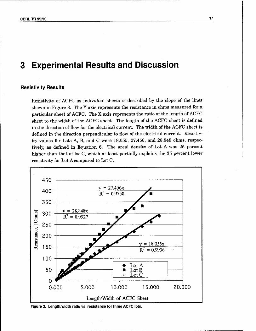
Resistivity of ACFC as individual sheets is described by the slope of the lines shown in Figure 3. The Y axis represents the resistance in ohms measured for a particular sheet of ACFC. The X axis represents the ratio of the length of ACFC sheet to the width of the ACFC sheet. The length of the ACFC sheet is defined in the direction of flow for the electrical current. The width of the ACFC sheet is defined in the direction perpendicular to flow of the electrical current. Resistiv- ity values for Lots A, B, and C were 18.055, 27.456, and 28.848 ohms, respec- tively, as defined in Equation 6. The areal density of Lot A was 25 percent higher than that of lot C, which at least partially explains the 35 percent lower resistivity for Lot A compared to Lot C.
I o
Pi
450
400
350
300
250
200
150
100
50
0 0.
y = 27.456x y R2 = 0.9758 Sw
y = 28.848x Am
R2 = 0.9927 m f
ms ^*^
Y *r V = 18.055x Jr t*r ' R2 = °"36
♦ Lot A LotB LotC
1 !
000 5.000 10.000 15.000
Length/Width of ACFC Sheet
20.000
Figure 3. Length/width ratio vs. resistance for three ACFC lots.

18 CERL TR 99/90
Table 2. Resistances of the assembled beds of ACFC, Lot C.
Adsorption Bed
Resistance of ACFC,
Unsaturated, 25°C Resistance of ACFC,
Saturated, 25°C Resistance of ACFC,
after desorption, 100°C
A 8.1 7.1 5.0 B 8.4 7.4 5.0
Resistance across the adsorption bed assembled with ACFC was 5.4 ohms at room temperature (-24 °C) for Lot A. Table 2 lists additional resistances for the assembled beds for Lot C. The width of the clamps on both ends of the ACFC bundles was ~ 4.45 cm. After subtracting this width, the measured resistances of the assembled bed of ACFC agree within 2 percent of the values computed by the resistivity correlations for individual sheets shown in Figure 3. This indi- cates that the resistance of an assembled adsorber can be accurately predicted from the resistance measurement of a flat sheet of ACFC.
These results also indicate that a, the thermal resistivity factor, is —5.25xl0"3
°C"\ However, additional data are needed to verify this value. The temperature for post-desorption conditions was measured in the gas ~ 5 to 10 mm away from the ACFC surface, and may not accurately reflect the temperature of the ACFC itself. The adsorbed MEK appears to decrease resistance of the unsaturated ACFC.
Adsorption Experimental Results
Pressure drop in the new adsorption bed is significantly reduced compared to the pressure drop in the original adsorber (Figure 4). At 5 Lpm total gas flow, the pressure drop is ~2 percent of the pressure drop for the original adsorber, About 11.4 cm of the ACFC's length as a cylinder was exposed directly to the gas flow. This configuration yields a cross-sectional area 4.3 times greater than the origi- nal adsorber. The superficial gas velocity through the ACFC in the new adsorber is 1.2 cm/sec at a total gas flow of 5 Lpm.
Figure 5 shows breakthrough curves from the original adsorber alongside typical breakthrough curves from the new adsorber. A comparison of the two shows that the new adsorber has no detectable channeling of MEK while MEK was adsorbed by the ACFC. There was initial concern regarding the length of MEKs mass transfer zone in the new adsorption beds that contained 16 instead of 90 layers of ACFC.

CERL TR 99/90 19
25
20 o
i is
Q
i VI en
10
_—-^y 5 1pm y = 2.5191x
R2 = 0.9923
O New Adsorber
■ Previous Adsorber
v = 0 6667x
■
1 R2 = 0.9841 t^Jb-G—^
- vy^ ^^ 1 1 1 i
4 6 Gas Velocity., [cm/s]
10
Figure 4. Comparison of the pressure drop through the first and second generation adsorbers.
1400
ppmv
ppmv
ppmv
980 ppmv
8 12 16 Adsorption Time [hrs]
20 24
Figure 5. Comparison of breakthrough curves of the first and second generation adsorbers.
20 CERL TR 99/90
Although the length of the adsorption zone is about one-third of the current bed length, the new design allows for reasonable TPR and LUB values, as described below. Configuring the cloth with more layers will result in higher electrical cur- rent passing through the ACFC at the same voltage during electro-thermal re- generation. The breakthrough curve for the new adsorption bed is slightly asym- metric, with a more rapid change in outlet concentration after ts than before tB.
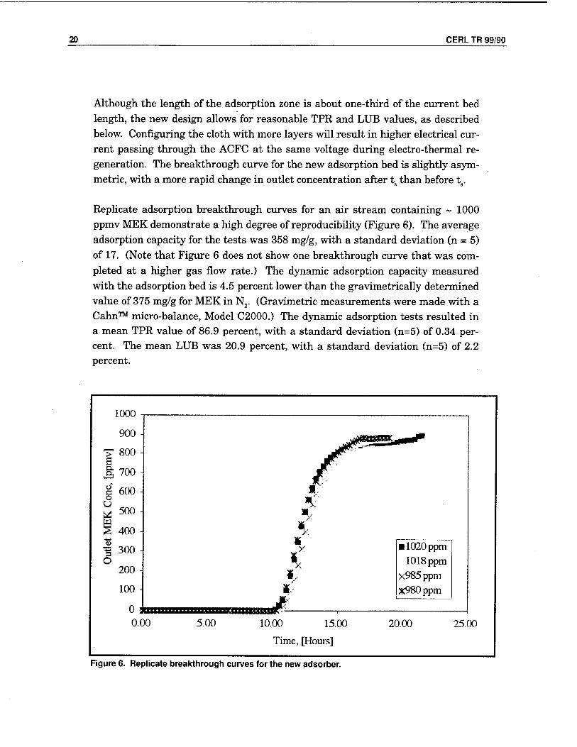
Replicate adsorption breakthrough curves for an air stream containing ~ 1000 ppmv MEK demonstrate a high degree of reproducibility (Figure 6). The average adsorption capacity for the tests was 358 mg/g, with a standard deviation (n = 5) of 17. (Note that Figure 6 does not show one breakthrough curve that was com- pleted at a higher gas flow rate.) The dynamic adsorption capacity measured with the adsorption bed is 4.5 percent lower than the gravimetrically determined value of 375 mg/g for MEK in N2. (Gravimetric measurements were made with a Cahn™ micro-balance, Model C2000.) The dynamic adsorption tests resulted in a mean TPR value of 86.9 percent, with a standard deviation (n=5) of 0.34 per- cent. The mean LUB was 20.9 percent, with a standard deviation (n=5) of 2.2 percent.
1000
900
T 800 e J; 700
g 600 o U a 500
S 400 -I
3 300 O
200
100
o mm o.oo 5.00 15.00
Time, [Hours]
■ 1020ppm 1018 ppm
x985 ppm *980ppm
20.00 25.00
Figure 6. Replicate breakthrough curves for the new adsorber.

CERL TR 99/90 21
Increase in temperature, MEK concentration, and gas flow rate result in de- creased breakthrough times for the system (Figure 7). The breakthrough curve with total gas flow rate of 7.5 Lpm showed a proportional reduction in break- through time, but did not exhibit any observable channeling or change in shape of the mass transfer zone. The system appeared capable of further increases in total gas flow rate assuming the reduced run time would accommodate the de- sorption cycle.
Adsorption tests were also performed to demonstrate performance of the adsor- ber under high RH conditions. Two runs were performed at RH = 90 percent with the adsorber at room temperature. The adsorption capacity of MEK for these runs was 205 mg/g, resulting in a 43 percent reduction in MEK adsorption capacity compared to tests at dry conditions. Two additional runs were com- pleted with the same dew-point temperature (Tdp) but increasing the dry-bulb temperature by 10 °C. The adsorption capacity of MEK for these tests was 281 mg/g, a reduction of 21 percent from the dry adsorption capacity tests. Figure 8 summarizes results from these tests and the MEK adsorption capacities during desorption cycles.
1200
1000
s ex 800
0" c 0 U 600
N § 400
0 200
0
.». A
4. ♦
• ,*<***
▼ ▼
•
•
♦ 4.
# + • +
X X
X ♦ 4360 ppm X980 ppm • 7.5 lpm +35°C
♦ +
X X
♦ ♦
• + +
JK
X
—-—
0.00 5.00 10.00
Time, [Hours]
15.00 20.00
Figure 7. Breakthrough curves for different operating conditions. (The curve for 4360 ppmv is normalized with 100% being equal to 1000 ppmv.)

22 CERL TR 99/90
•
fc. '
'■
.
ft
P l i i
Adsorption, Tdp= -12°C Adsorption, Tdp = 22°C
7.5 1pm 5 1pm
Bed Temp = Ambient, 24°C Bed = 34°C
K
k
-5-
i
Desorption
11pm
Bed=100°C
Figure 8. Comparison of adsorption capacities.
Experimental Desorption Results
Figure 9 shows desorption curves obtained under manual control of electrical power applied to the adsorption beds. Voltage was controlled between 12 and 20 V during the tests. Mass of MEK desorbed for these runs averaged 330.5 mg/g with a standard deviation (n=3) of 12. The desorbed mass averaged 92 percent of the adsorbed mass, indicating mass closure within 8 percent for MEK adsorption and desorption cycles.
Figure 10 shows the dependence of outlet MEK concentration and bed tempera- ture on duration of the desorption cycle. Voltage is automatically controlled by the SCR and the PID function in the DACS. The setpoint for the beds' outlet MEK concentration was manually changed from 0.5 to 3.5 percent at 1400 sec, resulting in the step change in MEK concentration and the smaller step change in bed temperature. Increasing voltage applied to the bed results in an almost instantaneous increase in the desorption of MEK. The 2-minute lag time in the response from the FID results in the oscillation in the desorbed MEK concentra- tion. The temperature of the adsorbent increases dramatically when a majority of the MEK has been desorbed. Such response indicates that electrical energy is consumed due to the heat of desorption of the MEK until the bed is nearly re- generated. As less MEK is available to desorb from the ACFC, more electrical energy is consumed by heating the ACFC. The mass of MEK evolved during the desorption test (Figure 10) is 96 percent of the MEK mass for the corresponding adsorption test.

CERL TR 99/90 23
s o ?3
12
10
8
6
4 S o a U 2
■ Desorb 3 xDesorb4
Desorb 5
0 +■ 1500 2000
Time, [Seconds]
3500
Figure 9. Electro-thermal regeneration curves with voltage under manual control.
8 -|
7 -
6 -
^? £l 4 -
8 , U 3
2 -
1
0 - c
-250
-200
O
- 150 ^
I 2 o 100 s
H
-50
- 0
MFF Cnnr
Temp
'1 1 '"II
Il l.illl.lllli M1 1 .. . ,.i..l
< J. I. IJ _L>" l\;1.Vu.,ir.,tAiuummii
I""1 ^ ^ i i i (
) 1000 2000 • 3000 4000 50
Time, [Seconds]
OO
Figure 10. Electro-thermal regeneration curve with voltage under PID control.

24 CERL TR 99/90
Experimental Condensation Results
The condenser was tested to verify its ability to remove MEK from the regenera- tion gas stream (Figures 11 and 12). The condenser was tested at twice the nor- mal gas flow rate (2 Lpm) at the highest concentration readily generated by the gas generation system at that total flow rate (~ 4500 ppmv). The bath tempera- ture vs. effluent concentration was measured while cooling the bath with the re- frigeration system and while allowing the bath to naturally reheat. These two curves are designated "heating" and "cooling" in Figure 12. The experimentally determined "MEK concentration vs. temperature data" bracket the equilibrium MEK concentration data modeled by Equation 8. To estimate the recycle loop concentration, equilibrium conditions in the condenser can be assumed.
Development and Operation of the Automated ACFC Adsorption/Desorption/Cryogenic Condensation System
An automated ACFC adsorption/desorption/cryogenic condensation system was developed to allow continuous separation and recovery of MEK from a simulated gas stream. The system was developed to better understand the important pa- rameters needed to design the pilot-scale system. The system treated a net gas flow of 5 Lpm that contained 1,000 ppmv MEK in air. Each adsorption bed was regenerated with N2 gas at 1 Lpm. The system'allowed for reverse N2 gas flow in each adsorber during regeneration of the ACFC. Reverse flow provides for faster desorption, especially for high molecular weight compounds that may exist in industrial gas streams.

CERL TR 99/90 25
5000
4500
r-,4000
I 3500 tf 3000
'I 2500 § 2000
tS 1500
1000
500
0 0
-MEK, [ppm] -Temp, [°C]
30
20
10
r—i 0 u t-l
-10
-20 1 Ol
-30 tf .<!'
-40 1-1
-50
-60
-70
5000 10000
Time, [sec]
15000 20000
Figure 11. Condenser concentration and temperature vs. time for 2 Lpm flow.
Figure 12. Condenser effluent concentration vs. temperature.

26 CERL TR 99/90
The desorption stream passed through the cryogenic condenser to remove the concentrated MEK. The cryogenic constant temperature bath was set to -43 °C, which equates to a condenser discharge concentration of 1000 ppmv. The gas stream emitted from the condenser then passed through the bed that was ad- sorbing the 5 Lpm air stream containing 1000 ppmv MEK. Therefore, the total gas flow rate through the bed that was adsorbing MEK was ~ 6 Lpm at 1000 ppmv MEK when the second bed was experiencing electro-thermal regeneration. The system was operated with continuous detection of MEK at the outlet of the adsorbing bed with an FID. The adsorbing bed was taken offline for regenera- tion when breakthrough occurred. Breakthrough is defined when the MEK con- centration downstream of the adsorbing bed achieved 50 ppmv (5 percent of the inlet concentration). Figure 13 shows the automated system.
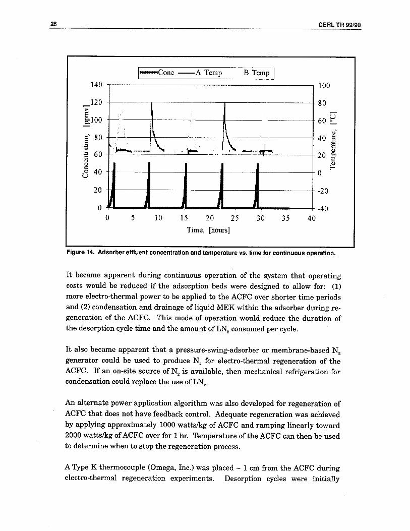
The automated bench-scale system was operated on a continuous basis with temperatures and concentration of MEK recorded (Figure 14). The top half of the figure shows the temperatures of the two adsorption beds (A and B). The lower half of the figure shows the concentration of MEK at the outlet of the bed that was adsorbing MEK. The bed that was adsorbing MEK was online for ~ 7 hr before breakthrough occurred.
CERL TR 99/90 27
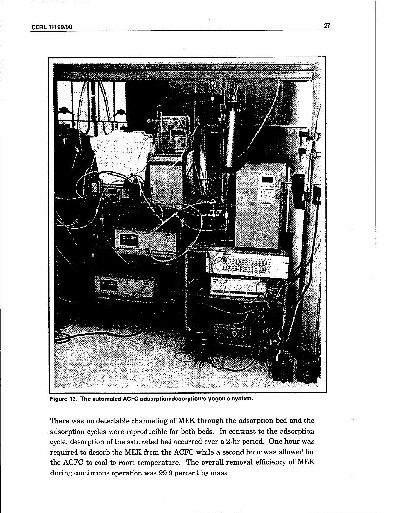
Figure 13. The automated ACFC adsorption/desorption/cryogenic system.
There was no detectable channeling of MEK through the adsorption bed and the adsorption cycles were reproducible for both beds. In contrast to the adsorption cycle, desorption of the saturated bed occurred over a 2-hr period. One hour was required to desorb the MEK from the ACFC while a second hour was allowed for the ACFC to cool to room temperature. The overall removal efficiency of MEK during continuous operation was 99.9 percent by mass.
28 CERL TR 99/90
Figure 14. Adsorber effluent concentration and temperature vs. time for continuous operation.
It became apparent during continuous operation of the system that operating costs would be reduced if the adsorption beds were designed to allow for: (1) more electro-thermal power to be applied to the ACFC over shorter time periods and (2) condensation and drainage of liquid MEK within the adsorber during re- generation of the ACFC. This mode of operation would reduce the duration of the desorption cycle time and the amount of LN2 consumed per cycle.
It also became apparent that a pressure-swing-adsorber or membrane-based N2
generator could be used to produce N2 for electro-thermal regeneration of the ACFC. If an on-site source of N2 is available, then mechanical refrigeration for condensation could replace the use of LN2.
An alternate power application algorithm was also developed for regeneration of ACFC that does not have feedback control. Adequate regeneration was achieved by applying approximately 1000 watts/kg of ACFC and ramping linearly toward 2000 watts/kg of ACFC over for 1 hr. Temperature of the ACFC can then be used to determine when to stop the regeneration process.
A Type K thermocouple (Omega, Inc.) was placed ~ 1 cm from the ACFC during electro-thermal regeneration experiments. Desorption cycles were initially

CERL TR 99/90 29
terminated at 100 °C, and subsequently lowered to 90 °C and then 80 °C. A desorption cycle terminating at 76 °C resulted in incomplete desorption.
Two additional continuous adsorption tests were completed to generate larger quantities of recovered MEK for the gravimetric material balance of the com- plete system. Each of these runs consisted of four adsorption/desorption cycles. Ninety-five and ninety-one percent of the MEK was recovered and sent to the adsorber beds during adsorption.

30 CERL TR 99/90
4 Pilot Design and Cost Estimates
A total gas flow rate of 0.5 mVmin is proposed for the pilot-scale adsorber. This is 100 times larger than the bench-scale system. The pilot-scale system can use industrial sized components, yet is still small enough to limit ACFC mass (cost) and to allow the system to be semi-portable. The adsorber's physical sizing and configuration takes into consideration the standard width of the ACFC material. The ACFC is available in a width of ~ 1 m. This width is sufficient for the pilot unit's size and allows for minimal waste of ACFC.
The bench-scale unit has relatively low electrical resistance, leading to high cur- rent and low voltage requirements. For an equivalent amount of energy applied, electrical costs are lower for a high voltage/low amperage combination. It is de- sirable to increase the resistance of the ACFC, as this will result in lower electric power costs during regeneration. Increasing the aspect ratio of the ACFC will increase resistance, but lower the number of sheets, or bed depth, of ACFC that the MEK-laden gas stream will pass through. Lower bed depth results in a lower TPR, which indicates less efficient use of the ACFC. These competing ob- jectives must be balanced to achieve the most economical system.
A modular system allows for maximum flexibility in configuring the unit for various test sites and conditions. Possible adsorber module configurations in- clude:
1. Tubular vessels constructed with nominal 8-in. OD pipe with flanged ends and a length of 2.5 m to accommodate two ACFC bundles in series. The system would consist of two of these vessels. This configuration would yield the lowest fabrica- tion labor cost.
2. Rectangular vessels of 1.5 m in length and 0.33 m by 0.33 m cross-section. Each of these vessels can contain an array of four ACFC bundles. This configuration is more compact.
Either configuration of the adsorption beds will have end plates constructed of an insulating material in order to electrically isolate the ACFC bundles. All four ACFC bundles in the adsorption train should be electrically connected in series. Figure 15 shows a conceptual drawing of the pilot system. The proposed ACFC modules are drawn to scale, assuming the human figure is 6 ft in height, while the scale of the other elements in the drawing is only approximate.

CERL TR 99/90 31
8 total ACFC units, 3 in. diameter x 1 meter, inside 8 in. pipe
Valves
Control Pannel & Solenoids
Power Supply
& 500 gal Dewar
3[
Figure 15. Concept drawing of pilot scale system.
Table 3 lists a summary of the calculations related to the scale-up. The adsorp- tion capacity of MEK used for the calculations was the value obtained at the 10 °C elevated temperature, in case the feed stream is humid. The adsorption capacity was divided by the experimental TPR of 80 percent to get the working mass of ACFC. The run time corresponds to the bench-scale breakthrough test times. The superficial gas velocity was held constant for the bench-scale and pi- lot-scale systems.
Table 3. Design parameters for bench and pilot systems.
Design Parameter Bench-Scale Pilot-Scale Units
Total gas flow rate 0.005 0.500 m3/min
Concentration of MEK 1000 1000 Ppmv
Molecular weight 72 72 g/mole
Adsorption capacity, x/m 0.275 0.275 g/g Breakthrough/run time 6.0 6.0 hr
Superficial gas velocity (ACFC) 1.35 1.35 cm/sec
Mass MEK recovered/hr 0.00096 0.0964 kg/hr
Mass MEK recovered /cycle 0.0058 0.579 kg MassACFC/bed 0.026 2.630 kg Number of beds 2.0 2.0 ea. ACFC mass for two bed system 0.053 5.260 kg Cost/kg ACF-5092-20 733 733 $ Total cost of ACFC 39 3,857 $

32 CERL TR 99/90
Design Parameter Bench-Scale Pilot-Scale Units
Aspect ratio (L/W) of ACFC . 0.434 0.900 na*
AC FC cartridges/bed 2 4 ea.
ACFC cartridges in series 2 2 ea.
ACFC electrically parallel units 1 1 ea.
Surface area of ACFC/bed 0.175 17.532 mA2
Carbon length (electrical) 0.276 3.972 m
Min physical vessel length 0.138 0.993 m
Hydraulic bundle area 0.00617 0.61728 mA2
ACFC cartridge diameter 0.021 0.101 m
Layers ACFC/cartridge 9.614 13.876 ea.
Resistance of bed 8.23 24.07 ohms
Power consumption 53 5260 Watts
Current 2.5 14.8 Amp
Voltage 20.8 355.8 V
* = not applicable
The recommended power supply for regeneration is a 460V, 60 amp model as it is only marginally more costly than a 40 amp model. If the ACFC is electrically configured as 2-2 series parallel, the adsorber specifications change, and a higher power application rate is desired.
The system cost estimate (Table 4) does not include additional diagnostic sen- sors/analyzers for FIDs/PIDs/RH/flow detection and data acquisition system ad- ditional capacity modules to accommodate the detectors. These items would add ~ $40,000 of additional temporary cost to the pilot-scale system.
Table 4. Pilot-scale system cost estimate.
Item Cost [$] Source
ACFC 3,857 American Kynol
Control system 8,000 Intuitech, SLC
Valves 7,880 Windustrial, SLC
Vessels 4,000 Ul Machine Shop
Pipe/ducts & fittings 2,000 McMaster-Carr
Power supply 3,000 Robicon, New Kensington, PA
Skid/frame 1,000
Sensors 1,964 Intuitech, SLC; Omega, Stamford CT
Condenser 3,500 Tranter, Wichita Falls TX
Vessel heating & insulation 1,000 McMaster-Carr
Supply blower 763 McMaster-Carr
Materials subtotal 36,964
Tax, freight 4,436 12%
Design & assembly 18,482 50%
Total equipment cost 59,882

CERL TR 99/90 33
The proposed control system is based on a Modicon™ or Allen-Bradley™ stan- dard industrial Programmable Logic Controller (PLC) with a rack-mounted per- sonal computer running the Windows® NT™ operating system and Wonder- ware™ Man Machine Interface (MMI) software. System capabilities include data logging, real time and historical trending, remote access and system pro- gramming via the Web, data reporting via email, and system alarm reporting via phone. This is a standard industrial turn-key product identical to that used on full-scale systems. All programming, control algorithms, graphic interfaces, etc., would be directly transferable to a full-scale system. The control system pricing includes a NEMA 4X control panel enclosure and solenoids to actuate all of the valves in the system.
The pricing for the valves includes pneumatic actuators. Pneumatic-actuated valves offer several advantages including lower cost, ease of manual operation, and increased safety (they are explosion proof).
Condensation of the MEK is achieved with LN2. The mass consumption ratio of LN2 to MEK is = 10:1. The dewar can be rented from an LN2 supplier for the pi- lot-scale system. The LN2 volume required for cooling is more than the volume required for purging during regeneration. The N2 flow sequence would be from: (1) the dewar, to (2) the tube side of the heat exchanger, to (3) the desorbing ves- sel, to (4) the shell side of the heat exchanger, through (5) a condensate trap, and then (6) merging the stream with the influent stream entering the vessel that is adsorbing MEK, and then (7) venting the gas stream to the atmosphere with the clean effluent carrier gas stream. The pilot-scale system should be constructed of stainless steel.
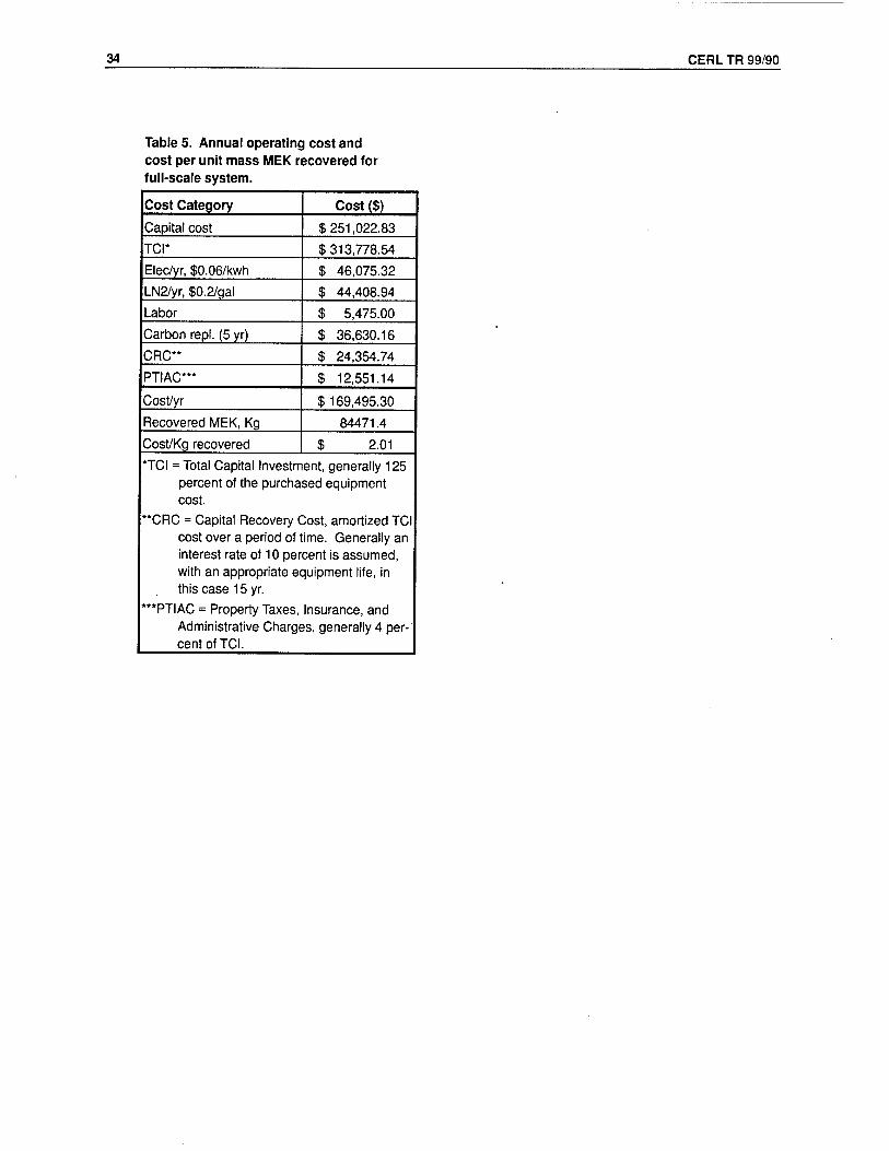
Table 5 lists the projected operating costs of a full-scale system. Methods used to estimate the operating costs are provided by Vatavuk (1990).
A carbon life of 5 years was assumed. A lower consumption ratio of N2:MEK of 7:1 was also assumed. A process size of 50 m3/min at 1000 ppmv was selected, or ~ 100 times the size of the pilot-scale unit. The estimate shows a cost per recov- ered kilogram of MEK at ~ $2. This figure indicates that the ACFC adsorp- tion/cryogenic recovery system can be an economically viable means to capture and recover MEK.
34 CERL TR 99/90
Table 5. Annual operating cost and cost per unit mass MEK recovered for full-scale system.
Cost Category Cost ($)
Capital cost $251,022.83
TCI* $313,778.54
Elec/yr, $0.06/kwh $ 46,075.32
LN2/yr, $0.2/gal $ 44,408.94
Labor $ 5,475.00
Carbon repl. (5 yr) $ 36,630.16
CRC** $ 24,354.74
PTIAC*** $ 12,551.14
Cost/yr $ 169,495.30
Recovered MEK, Kg 84471.4
Cost/Kg recovered $ 2.01
*TCI = Total Capital Investment, generally 125 percent of the purchased equipment cost.
"CRC = Capital Recovery Cost, amortized TCI cost over a period of time. Generally an interest rate of 10 percent is assumed, with an appropriate equipment life, in this case 15 yr.
***PTIAC = Property Taxes, Insurance, and Administrative Charges, generally 4 per- cent of TCI.

CERL TR 99/90 35
5 Summary and Conclusions
An automated bench-scale activated carbon fiber-cloth (ACFC) adsorption sys- tem was designed and built to simulate the capture and recovery of dilute haz- ardous air pollutants (HAPs) from gas streams. The new design for the adsorber does not limit ACFC temperatures during electro-thermal desorption. This con- figuration will allow future optimization to reduce desorption cycle times. The new design is simple and inexpensive to construct and maintain, and also has the added benefits of low pressure drop.
The adsorber has operated under high humidity conditions. It was shown that increasing the adsorption bed's dry-bulb temperature by 10 °C (at the same dew point temperature) can reduce the adverse effects of treating high humidity gas streams in half.
Careful material balances were performed for adsorption and desorption cycles. Dynamic adsorption capacities are within 5 percent by mass MEK with gra- vimetrically determined results. Adsorption and desorption cycling test results are within 7 percent when comparing influent mass of MEK to adsorbed and condensed mass of MEK.
Set points and algorithms have been developed for continuous and automated operation of the system. Continuous adsorption, desorption, condensation, and recovery of MEK has been demonstrated.
A preliminary design and cost estimate for a pilot-scale system is also provided. An economic analysis of a proposed full-scale ACFC adsorption/electro-thermal regeneration/condensation system shows that a process recovery cost of $2/kg of MEK is achievable.

36 CERL TR 99/90
References
Cal, M.P., M.J. Rood, et al.,"Removal of VOCs from Humidified Gas Streams Using Activated Car- bon Cloth," Gas Separation and Purification (1996), vol 10, No. 2, pp 117-121.
Cheremisinoff, N.P., and P.N. Cheremisinoff, Carbon Adsorption for Pollution Control (Prentice Hall, Englewood Cliffs, NJ, 1993).
Hayes, Joseph S.,"Novoloid Fibers," in Encyclopedia of Chemical Technology, Kirk-Othmer, ed. (John Wiley & Sons, Inc., 1981), vol 16, pp 125-138.
Lindeburg, M.R., EIT Review Manual (Professional Publications, San Carlos, CA, 1982).
Lordgooei, M., K.R. Carmichael, et al., Development of an Activated Carbon Fiber Cloth Adsorp- tion/Regeneration System To Recover and Reuse Toxic Organic Compounds (Champaign, IL, Hazardous Waste Research and Information Center, 1996), p 206.
Reid, R.C., J.M. Prausnitz, and B.E. Poling, The Properties of Gases and Liquids, 4,h ed. (McGraw Hill, 1987).
Rood, M.J., M. Lordgooei, et al., Removal and Recovery of Organic Vapor Emissions by Fixed-Bed Activated Carbon Fiber Adsorber-Cryogenic Condenser, Technical Report (TR) 99/05, ADA366689PAA (U.S. Army Construction Engineering Research Laboratory [CERL], Decem- ber 1998).
U.S. Environmental Protection Agency (USEPA), "1995 TRI Public Data Release Overview," found in:
http://www.epa.gov/opptintr/tri/pdr95/drover01.htm (1998)
USEPA, Clean Air Act as amended in 1990, found in http://www.epa.gov/oar/caa/contents.html
Vatavuk, W.M., Estimating Costs of Air Pollution Control (Lewis Publishers, Chelsea, MI, 1990).

CERL TR 99/90 &_
DISTRIBUTION
Chief of Engineers ATTN: CEHEC-IM-LH (2) ATTN: HECSA Mailroom (2) ATTN: CECC-R ATTN: CERD-L ATTN: CERD-M
Defense Tech Info Center 22304 ATTN: DTIC-0(2)
9 11/96

REPORT DOCUMENTATION PAGE Form Approved OMB No. 0704-0188
Public reporting burden (or this collection of information is estimated to average 1 hour per response, including the time for reviewing instructions, searching existing data sources, gathering and maintaining the data needed, and completing and reviewing the collection of information. Send comments regarding this burden estimate or any other aspect of this collection of Information, including suggestions for reducing this burden, to Washington Headquarters Services, Directorate for information Operations and Reports. 1215 Jefferson Davis Highway Suite 1204 Arlington VA 22202-4302, and to the Office of Management and Budget, Paperwork Reduction Project (0704-0188). Washington, DC 20503
1. AGENCY USE ONLY (Leave Blank) 2. REPORT DATE
November 1999 3. REPORT TYPE AND DATES COVERED
Final 4. TITLE AND SUBTITLE
Removal and Recovery of Methyl Ethyl Ketone (MEK) Vapor Emissions by Carbon Fiber Adsorber-Cryogenic Condenser
6. AUTHOR(S)
Mark J. Rood, Patrick D. Sullivan, Mehrdad Lordgooei, Shaoying Qi, and K. James Hay
7. PERFORMING ORGANIZATION NAME(S) AND ADDRESSES)
U.S. Army Construction Engineering Research Laboratory (CERL) P.O. Box 9005 Champaign, IL 61826-9005
9. SPONSORING / MONITORING AGENCY NAME(S) AND ADDRESS(ES)
Headquarters, U.S. Army Corps of Engineers (HQUSACE) 20 Massachusetts Ave., NW Washignton, DC 20314-1000
5. FUNDING NUMBERS
62720 D048 T88
PEFORMING ORGANIZATION REPORT NUMBER
TR 99/90
10. SPONSORING / MONITORING AGENCY REPORT NUMBER
9. SUPPLEMENTARY NOTES
Copies are available from the National Technical Information Service, 5385 Port Royal Road, Springfield, VA 22161
12a. DISTRIBUTION / AVAILABILITY STATEMENT
Approved for public release; distribution is unlimited.
12b.DISTRIBUTION CODE
13. ABSTRACT (Maximum 200 words)
The Clean Air Act Amendments of 1990 mandate the reduction of emissions of hazardous air pollutants (HAP). Activated carbon fiber-cloth (ACFC) offers promise as a superior adsorbent to remove and recover organic HAP from gas streams. This study designed, built, and tested a second-generation system with an improved adsorber using methyl ethyl ketone (MEK) as the organic pollutant. Total flow rate of the bench-scale system was 5 Lpm with the gas stream containing 1000 ppmv MEK. Breakthrough times ranged between 11.9 and 12.9 hr. Throughput ratios of 86.9 percent were achieved. Electrothermal regeneration times were approximately 1 hr at 100W.
It was shown that increasing the adsorption bed's dry-bulb temperature by 10 °C can cut adverse effects of treating high humidity gas streams in half. The system was automated to demonstrate continuous MEK adsorption, desorption, condensation, and recovery. Overall removal efficiency during continuous operation was 99.9 percent by mass. The study's preliminary design and cost analysis for a pilot-scale system estimates a cost of $60,000 for a flow rate of 0.5 m3/min and a concentration of 1000 ppmv. An economic analysis of a proposed full-scale system shows that a process recovery cost of $2/kg of MEK is achievable.
14. SUBJECT TERMS
air pollution control technologies air emissions methyl ethyl ketone (MEK)
activated-carbon hazardous air pollutants (HAPs)
17. SECURITY CLASSIFICATION OF REPORT
Unclassified
NSN 7540-01-280-5500
18. SECURITY CLASSIFICATION OF THIS PAGE
Unclassified
19. SECURITY CLASSIFICATION OF ASTRACT
Unclassified
15. NUMBER OF PAGES
40 16. PRICE CODE
20. LIMITATION OF ABSTRACT
SAR
Standard Form 298 (Rev. 2-89) Prescribed by ANSI Std 239-18 298-102