renewable energy materials qxu7027 batteries
TRANSCRIPT

Renewable Energy MaterialsQXU7027
Batteries
Zhe LiSenior Lecturer of Materials Science
QMUL/[email protected]

Li-S Operation - Discharge

Na ion Battery• Sodium analogue of the Li ion battery• NiMnO2 layered cathode– intercalation of Na+ in the same way as Li ion• Amorphous or ‘hard’ carbon negative electrode – no intercalation. Na bonds to
carbon at sites of defects and pores• Operating principle is the same as Li ion• 3.6 V, 115 mAh g-1

Flow Batteries

Flow Batteries

Flow Batteries
Power
Energy Energy

Flow Batteries
• Electrolyte containing the redox active species is stored in tanks and pumped into a cell
• Redox reactions take place in the cell, charging or discharging the system• Separation of energy and power: the energy capacity of the system is given by
the amount of electrolyte (size of tanks), the power of the system by the size of the cell, or stack of cells
• This gives flexibility in design, and also easy and cheap to increase the storage of the battery
• Can be thought of as in between a battery and a fuel cell, or as a regenerative fuel cell
• Application in large scale grid storage• Carbon felt electrodes in the cell provide reaction sites• Separator: Proton conducting membrane (Nafion)

All Vanadium Redox Flow Battery
• Uses 4 oxidation states of V for the two redox couples
• V(II)/V(III) redox couple on the negative electrode (anode)
• V (IV)/V(V) redox couple on positive electrode (cathode)
• Vanadium dissolved in sulphuric acid solution• During Discharging: V(II)>V(III) and V(V)>V(IV)• During Charging: V(III)>V(II) and V(IV)>V(V)• In systems with different chemistries on the anode
and cathode, cross over causes irreversible loss of capacity, expensive electrolyte separation and possible contamination of incompatible electrolytes. All-V RFB systems can be electrochemically regenerated with cross over, without having to separate or chemically alter the electrolytes

All Vanadium Redox Flow Battery

Flow Battery Advantages• Long life – minimal degradation, simple electrodes that do not go
through physical changes (cf Li ion)• Separation of power and energy – modular• Little self discharge – electrolyte stored in two separate external
tanks, so can not self react when not in use – long duration storage• Well suited to large scale grid storage – MW systems have been
demonstrated• Low maintenance• Easy state of charge determination (relative concentration of species)• Tolerance to overcharge and full discharge• Safe as active materials stored separately from the source of reaction
(cell)

Flow Battery Disadvantages
• Higher system requirements – pumps, sensors, flow management, power management
• Parasitic power losses from pumping• Vanadium has significant cost• Vanadium is not very soluble – requires strong acid• Flow batteries typically operated at low current densities, around
50 mA cm-2 – low power density• New technology, much research still required into electrodes, different
chemistries with high potential, stability, solubility and reaction kinetics, selective membranes with good conductivity, cell design
• Not portable

Flow Battery Chemistry• All V is by far the most widely studied, but
many chemistries are possible: Iron Chromium, Hydrogen Bromide, Zinc Bromide etc
• As long as there is a redox couple, a flowbattery could be made
• Organic couples may be the future –larger molecules reduce cross over, potential to tailor the species, potentially much cheaper reactants, better solubility, wide range of candidates – on going research

Flow Battery Applications
• Grid Scale storage
• Load balancing (store excess power)
• Peak shaving – demand spikes met by the battery
• Back up power supplies• Stand alone power (off grid)
• Electric vehicles – ‘charge’ by replacing electrolyte

Renewable Energy MaterialsQXU7027
Fuel Cells
Zhe LiSenior Lecturer of Materials Science
QMUL/[email protected]


Hydrogen Economy

What is a fuel cell?
A fuel cell is a device that generates power by the combination of fuel and oxygen.
A fuel cell is a device that converts chemical energy directly into electrical energy.
It is a cross between an engine and a battery – it is an electrochemical engine.
Main features
- High efficiency
- Low or no emissions
- Quiet, no moving parts, potentially highly
reliable
- Scalable – applications from mW to MW

Types of Fuel Cell

Types of Fuel Cell
Proton Exchange Membrane

−+ +→ e2H2H2OH2H2O
2
12 2 →++ −+ eHOR
ORR
PEMFC

−+ +→ e2H2H2OH2H2O
2
12 2 →++ −+ eHOR
ORR
PEMFCH2(g) + ½O2(g) H2O(l)

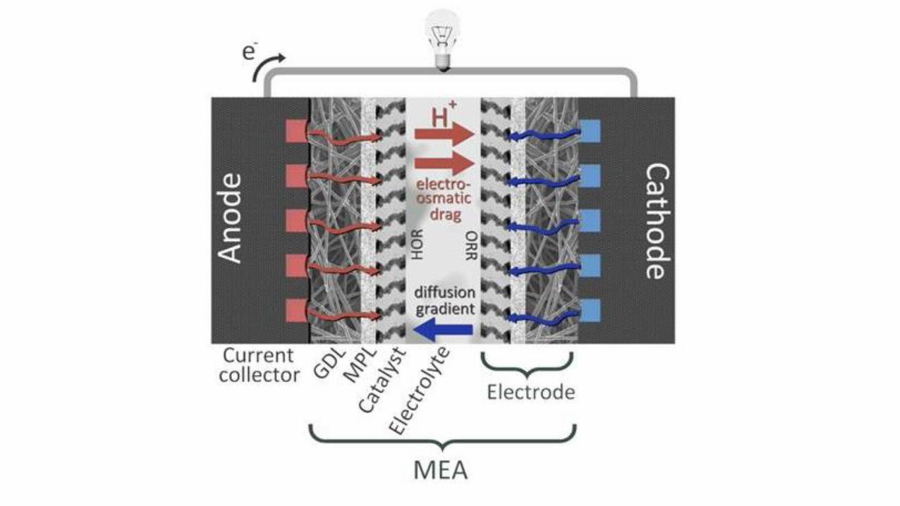
Materials For PEM Fuel Cells
• Current collector• MEA: membrane
electrode assembly• GDL: Gas diffusion
layer• MPL: Microporous
Layer• Catalyst • Electrolyte

Fuel Cell Components
• Membrane: Solid proton (hydrogen ion) conducting polymer
• Electrodes: Catalyst containing ink deposited on a gas diffusion carbon paper (on the GDL)
• MEA: Two electrodes hotpressed with membrane to make membrane electrode assembly – the working part
• Current collectors: graphite composite plates/metals –allow conduction of electrons and flow of gases

Fuel Cell Components
CatalystMembrane (Nafion)
Current Collectors
100 m
Gas Diffusion Layer

Desirable Properties
• Membrane: good proton conduction, poor electron conduction, impermeable to gases, good mechanical and chemical stability (must not degrade) – Nafion is industry standard: PTFE backbone with sulphonic acid groups
• Gas diffusion layer: porous, even distribution of gases, electrically conductive, often coated in PTFE to help with water removal
• Microporous layer: carbon ink typically used
• Catalyst layer: usually platinum nanoparticles supported on carbon supports to increase surface area to volume ratio (reduce cost). Good activity for the HOR and ORR reactions, chemically stable, durable after many cycles
• Current collectors: electrically conductive, strong, machinable

Platinum Price volatility
Blue – Pt
Gold – Au
Prices in USD per troy ounce
(troy ounce = 31.1g)
Unlike gold, the price of platinum and palladium tends to rise during periods of economic stability, and decreases during more uncertain times. This is likely because demand grows in industries like jewellery and electronics when people are feeling more economically secure, and show greater demand for products that contain platinum

Reducing Pt content in Fuel CellsMany approaches have been used to reduce the amount of Pt in fuel cells. As the reactions occur at the surface of the catalyst, most of the approaches involve increasing the surface area to volume ratio of Pt
Approaches currently used to improve Pt activity
• a. Alloying with one or more other metals;
• b. Layering Pt on or just below the surface of another metal;
• c. A core–shell approach; a core of cheaper metal is coatedwith Pt;
• d. Non-Pt catalysts such as Ni, doped
Carbons (N, P) etc – tend to have greater
activity in alkaline conditions

Summing up: Advantages of PEM Fuel Cell
• Efficient
• No emissions at point of operation
• Potentially highly reliable (no moving parts)
• Flexibility – current (power) proportional to area of cell
• Continuous operation (with fuel supply)
• Low operating temperature-Low ‘charge’ times

Disadvantages• Cost
• Total system cost US $67 kW-1 (excluding fuel storage)• 60% attributed to the fuel cell stack• 29% to the fuel processor• 8% to assembly and indirect costs• 3% to balance of plant.
• Materials make up 81% of the total system cost (Ptcatalyst - most of the cost).
• Infrastructure• Hydrogen availability, fuelling stations
• Reliability

Types of Fuel Cell
Solid Oxide Fuel Cell

Solid Oxide Fuel Cell
• Use a ceramic oxide material as electrolyte
• Conduct O2- anions through the electrolyte
• Still use HOR and ORR
• Operate at much higher temperatures. 500-1000 oC due to resistance of electrolyte
• Require heating – mostly stationary generation applications, up to 2 MW output
• As well as planar geometry can be tubular

Solid Oxide Fuel Cell (SOFC)
• At higher temperatures, the activation losses are much less and so platinum catalysts are not required
• Higher temperatures also make them less vulnerable to poisoning from impurities such as CO.
• Electrolyte: Ceramic, typically YSZ (yttria stabilized zirconia). Does not conduct O2- until high temperatures
• Anode: Ni mixed with the electrolyte material. Porous, electron conducting
• Cathode: Lanthium strontium manganate (LSM) used currently – electronically conductive and O2- conductive.

SOFC Pros and Cons
Advantages
• No need for expensive catalyst due to high temperature
• Better tolerance for impurities in the gas stream
• Combined heat and power of waste heat improves the efficiency
• Can use a variety of fuels, not just hydrogen. Syngas, internal reforming of methane
• Efficiency of around 60% achieved – this is close to the max for high temperature (thermodynamics)
• Can be installed into existing methane grids
Disadvantages
• Must heat the cell. Slow start up time
• High temperature means that all components must be well engineered
• Thermal gradients and heating/cooling can crack materials and lead to degradation
• Not very mobile
• Low ionic conductivity

Types of Fuel Cell
Direct Methanol Fuel Cell

Direct Methanol Fuel Cell (DMFC)• Similar setup to the PEM fuel cell, but with methanol as
the fuel
• Temp range –60 - 130 oC
• Liquid methanol is energy dense and easy to store and transport. Cheap
• Poor efficiency and power produced. Applications limited to small portable devices currently
• Methanol cross over is a big problem – MeOH on the cathode side reacts with air and reduces the cell voltage

Types of Fuel Cell
Solid Oxide Fuel Cell

Alkaline Fuel Cell - AFC• Precedes the PEM – invented by Bacon
• Uses aqueous KOH as electrolyte
• Used on the Apollo missions
• KOH can convert to K2CO3 on reaction with CO2 – this contaminate the electrolyte and reduces concentration. Therefore can’t use in air- need pure O2. Also H2 needs to be purified of CO2
• Carbonates can precipitate and block the electrodes
• Liquid electrolyte represents a leaking risk – caustic. It was for this reason that the PEM fuel cell was pursued
H2 + 2OH− → 2H2O + 2𝑒
−
1
2O2 + 2𝑒− + H2O → 2OH−

25 - 30 % efficiency*
Combustion
Limited by Carnot cycle
~120 g CO2 / km
GASOLINE CAR
ELECTRICCAR
70 - 85 % efficiency
Electrochemical
~0-80 g CO2 / km
50 - 60 % efficiency
Electrochemical like electric vehicle
~0-120 g CO2 / km
FCEV Comparison
Hydrogen energy s
ource
Renewable sources li
ke wind and solar wo
uld afford FCEVs that
are almost truly ZER
O-EMISSIONS
vehicles.

Fuel Cell Stacks
• Individual cells connected in series
• Gives useful operating voltages and power
Anode
Cath
ode
Ele
ctro
de
Inte
rconnect
Inte
rconnect
Anode
Cath
ode
Ele
ctro
de
Inte
rconnect
Inte
rconnect
Anode
Cath
ode
Ele
ctro
de
Inte
rconnect
Inte
rconnect
Anode
Cath
ode
Ele
ctro
de
Inte
rconnect
Inte
rconnect
Anode
Cath
ode
Ele
ctro
de
Inte
rconnect
Inte
rconnect

Commercially available 3 kW Horizon stack
100 cells in series
70 V

Differences: FCs and Batteries
• Closed system• Reactants are consumed• It needs charging
• Open system• Reactants are in contact
with a Pt catalyst• Reactants are externally
supplied• No charging is required
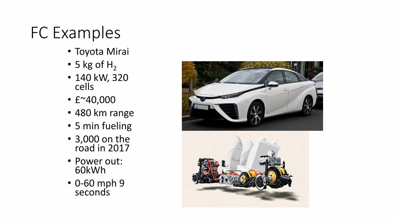
FC Examples• Toyota Mirai• 5 kg of H2
• 140 kW, 320 cells
• £~40,000• 480 km range• 5 min fueling• 3,000 on the
road in 2017• Power out:
60kWh• 0-60 mph 9
seconds

FC Examples• Hyundai Tuscan
• Available for lease in CA
• $500/month
• 410 km range

• Honda Clarity
• On sale from 2017 in California
• 589 km range
• 103 kW motor
FC Examples

FC Examples• RV1 – Fuel Cell Bus
• Fuelling station in east London
• 18 hours without refulling
• Many other cities: Madrid, Hamburg, Reykjavik, Perth

Renewable Energy MaterialsQXU7027
Zhe LiSenior Lecturer of Materials Science
QMUL/[email protected]
Super Capacitors

Capacitors

Capacitors

Capacitors

Capacitors

Supercapacitors: An outline
• Supercapacitor is an electrical device that store 10 or 100 more
times charge higher than normal dielectric capacitor
• It is also known as ultracapacitors or electric double layer capacitors
• Delivers energy or charge very quickly (high power density)
• Low cost
• Supply instant and uninterruptable backup power with quick
discharging
• Used in Printers, cars and potable electronics devices


Schematic of a Supercapacitor
Typical construction of a
supercapacitor:
(1) power source,
(2) collector,
(3) polarized electrode,
(4) Helmholtz double layer,
(5) electrolyte having positive and
negative ions,
(6) separator.

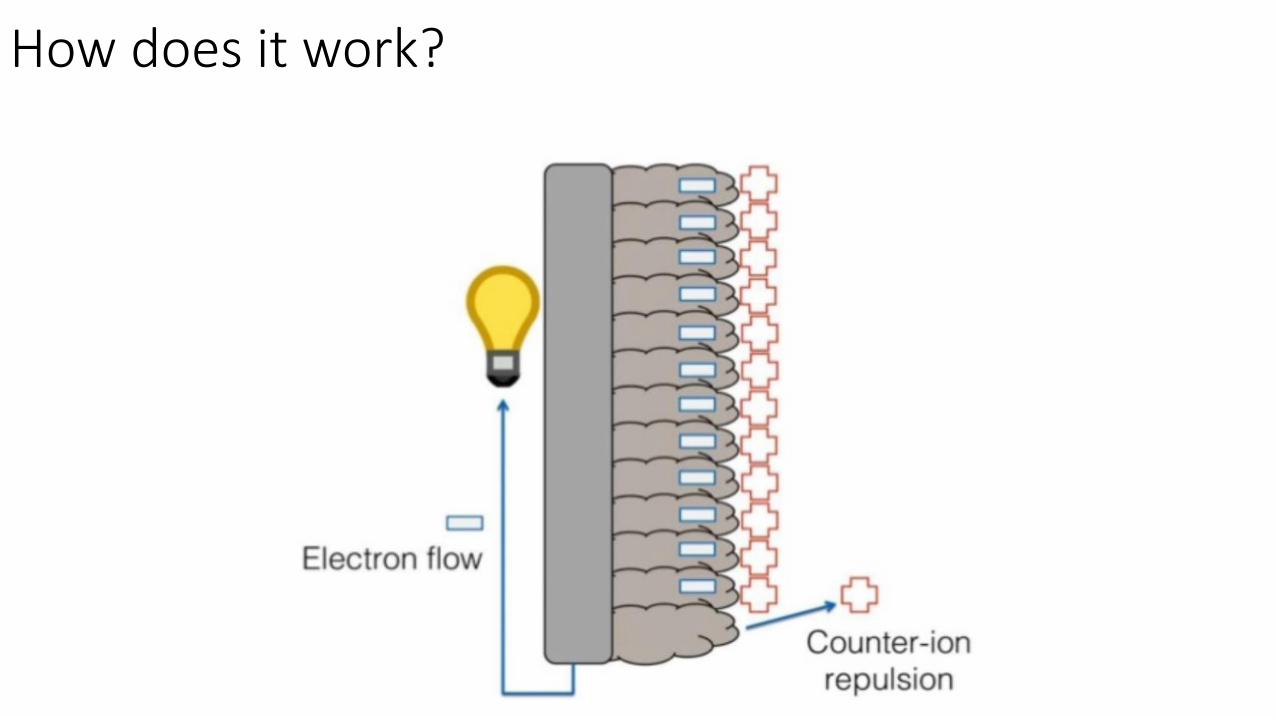
How does it work?

How does it work?

How does it work?

How does it work?
Distance between the thin charged layer is ~3-8 angstroms

How does it work?
“Electric double layer capacitor”

Highly porous electrode materials
provide large surface area
How does it work?

Capacitors
How does it work?


