repon ball bearing slidesdownloads.nover.com.au/public/brochures/repon-ball-bearing-slide...if not,...
TRANSCRIPT

EDITION 1: 2013
REPON BALL BEARING SLIDES

02 www.nover.com.au www.nover.com.au 03
CONTENTS PAGESTANDARD FULL EXTENSION SLIDES 04
45KGS 04
90KGS 08
SUPER HEAVY DUTY SLIDES 12
180KGS 12
SOFT CLOSE 16
45KGS 16
60KGS 20
TOUCH TO OPEN 24
45KGS 24
STAINLESS STEEL SLIDES 28
65KGS 28
POCKET DOOR SLIDES 32
11KGS 32

www.nover.com.au 0504 www.nover.com.au
STANDARD FULL EXTENSION SLIDESFULL EXTENSION LOAD CLASS 45KGSSide mounted
Side Clearance | 12.7mm plus 1/32”, minus 0 each side.
Loading | 45kgs class.
Size | 250mm through 700mm in 50mm increments.
Feature | 32mm hole pattern, easy access windows to reach each hole on cabinet member in closed position, breather tab self adjustment to accommodate variation in side clearance.
Packaging• 250mmto600mmcontain15pairspercarton• 650mmto700mmcontain10pairspercarton
Profile45.7
12.7
SIZE TL A B C D E F G H I J CODE
250mm 254.00 250.00 192.00 421270
300mm 304.80 300.00 224.00 224.00 128.00 421271
350mm 355.60 350.00 224.00 292.00 128.00 421272
400mm 406.40 400.00 320.00 224.00 342.00 128.00 421273
450mm 457.20 450.00 352.00 224.00 392.00 320.00 128.00 421274
500mm 508.80 500.00 416.10 224.00 442.00 320.00 128.00 421275
550mm 558.80 550.00 352.00 224.00 492.00 416.00 128.00 421276
600mm 609.60 600.00 480.00 352.00 224.00 542.00 416.00 224.00 128.00 421277
650mm 660.40 650.00 544.10 352.00 224.00 592.00 544.00 416.00 224.00 128.00 421278
700mm 711.20 700.00 544.10 352.00 224.00 642.00 544.00 416.00 288.00 224.00 128.00 421279
SPECIFICATIONS

www.nover.com.au 0706 www.nover.com.au
STANDARD FULL EXTENSION SLIDESDRAWING
FULL EXTENSION LOAD CLASS 45KGS
φ4.6*5.3
φ4.6 9.5*φ4.6φ6.4
3.0
20.9
11.2
6.0
6.0
35.1
21.6
DC
B
480.032.0
35.1
8.9 (TYP)
12.7 (TYP)128.0
12.7
35.0 60.58.9 12.65
10.7
1.50
JI
HG
FE
26.0
A ±0.25
11.4 (TYP)
For 55mm ONLY
12.7
45.7
Profile
1 – Drawer or pull-out shelf must be at least 12.7 mm narrower than cabinet opening on each side. (DIM A)
2 – Bottom of drawer or pull-out shelf bottom shall have 6.4 mm minimum clearance from the bottom of cabinet. (DIM B)
3 – Mark a 61 mm line from the bottom of cabinet. (DIM C)
4 – Mark a 44 mm line from the bottom of drawer. (DIM D)
TECHNICAL SPECIFICATIONS FOR DRAWER OR PULL-OUT SHELF
12.7mm
6.4mm
61mm44.5mm
(DIM A)
(DIM B) (DIM C)(DIM D) *This instruction is for reference only. It may vary due to different applications.
FINAL ADJUSTMENT Try to open and close the drawer to see if slides function correctly. If so, secure the screws and install additional screws as necessary. If not, please make adjustment till slides function correctly.
B – Make sure the bearing retainers are fully forward. Insert drawer member into the cabinet member, and then close the drawer completely. (Figure 3.1)
Push down at right hand side or lift up at left hand side
Make sure retainer is fully forward
(Figure 3.1)
Insert drawer member into cabinet member
A – Fix the slides through the most flexible holes on breather tab for best slide performance. Leave the screw loose for final adjustment. Move the slides back and forth, and make sure no screw is bound.
INSTALLATION INSTRUCTIONS

www.nover.com.au 0908 www.nover.com.au
STANDARD FULL EXTENSION SLIDESFULL EXTENSION LOAD CLASS 90KGSSide mounted
Side Clearance |19.0mmplus1/64”,minus0eachside.
Height |53.6mm
Loading | 90 kgs class (size: 450mm).
Size | 400mm through 700mm at 50mm increments.
Feature | 32mm hole pattern hold/close function to prevent bounce back. Over-travel.
Packaging• 300mmto600mmcontain8pairspercarton• 650mmto700mmcontain6pairspercarton
Profile53.6
19.0
SIZE SL TL A B D E G CODE
400mm 400.25 426.0 96.0 96.0 96.0 96.0 13.0 421210
450mm 450.25 475.0 128.0 128.0 128.0 128.0 13.0 421211
500mm 500.25 525.0 160.0 128.0 160.0 128.0 86.5 421212
550mm 550.25 574.0 160.0 192.0 160.0 192.0 86.5 421213
600mm 600.25 623.0 224.0 192.0 224.0 192.0 86.5 421214
650mm 650.25 672.0 224.0 224.0 224.0 224.0 86.5 421215
700mm 700.25 721.0 256.0 256.0 256.0 256.0 86.5 421216
SPECIFICATIONS

www.nover.com.au 1110 www.nover.com.au
STANDARD FULL EXTENSION SLIDES
(TYP)
(TYP)
32.0G D E F
35.0 16.0 φ5.0(TYP) I(TYP)
SL
TL±3.0
35.0
32.0
16.0(TYP)
(TYP)
H(TYP)
A
B
Cφ5.0(TYP)
SL
19.0
53.6
10.6
2.0
2.0
90°
+0.2-0
0.6
φ5.1 2.0
10.6
2.0
90°
0.6
+0.2-0φ5.1
DRAWING
FULL EXTENSION LOAD CLASS 90KGS
1 – Drawer or pull-out shelf side clearance must be at least 19.00 mm. (DIM A)
2 – Bottom of drawer or pull-out shelf bottom shall have 6.4 mm or 1/4” minimum clearance from the bottom of Cabinet. (DIM B)
3 – Mark a center line with proper height ( H ) from the bottom of cabinet. (DIM C)
4 – Mark a center line with proper height (H-6.4 mm) from the bottom of drawer. (DIM D)
TECHNICAL SPECIFICATIONS FOR DRAWER OR PULL-OUT SHELF
Profile Component Parts
19.00 6.4
6.4
H
H-6.4
(DIM A)
(DIM B)(DIM D) (DIM C)
A – Align center line of cabinet member to pre-determined center line (H), and place slide 2 mm backward from cabinet opening. (Figure 1.1)
D – Fix the drawer member through vertical slots for vertical adjustment. Leave the screw loose for final adjustment.
*This instruction is for reference only. It may vary due to different applications.
FINAL ADJUSTMENT Try to open and close the drawer to see if slides function correctly. If so, secure the screws and install additional screws as necessary. If not, please make adjustment till slides function correctly.
C – Align center line of drawer member to the pre determined line (H-6.4 mm), and place drawer member 2 mm backward from the drawer front or the pull-out shelf edge.
B – Fix the slides through the countersunk holes, and leave the screw loose for final adjustment. Move the slides back and forth, and make sure no screw is bound.
(H-6.4mm)
2mm
(H)
2mm
Use hole on breather tab for side adjustment
Set the cabinet member 2mm back
Align top of cabinet member to (H) line
(Figure 1.1)
INSTALLATION INSTRUCTIONS

www.nover.com.au 1312 www.nover.com.au
SUPER HEAVY DUTY SLIDESFULL EXTENSION LOAD CLASS 180KGSSide mounted
Slide Clearance | 19.30mm
Height | 77.22 mm
Loading | 180kgsbasedonsidemount,anddrawerdimensionW1000mmx450mm,guaranteed 10,000 cycles, double-folded inner and internediate member.
Size | 500mm though 900mm at 100mm increments.
Feature | Extraheavyload,extremelysilentmovement.Silencingbumpers. ExclusiveLockIn&outmechauism.
Packaging• 500mmto600mmcontain4pairspercarton• 700mmto900mmcontain2pairspercarton
Profile77.2
19.3
SPECIFICATIONS
SIZE SL TL A B C F G H M N P Q CODE
500mm 508.0 508.0 88.9 152.4 344.5 387.3 4212881
600mm 609.6 609.6 88.9 152.4 360.4 446.1 25.4 488.9 4212882
700mm 711.2 711.2 88.9 152.4 462.0 547.7 25.4 590.5 4212883
800mm 812.8 812.8 88.9 152.4 330.2 563.6 649.3 25.4 215.8 374.6 533.4 692.1 4212884
900mm 914.4 914.4 88.9 152.4 330.2 665.2 750.9 25.4 215.8 425.4 635.0 793.7 4212885

www.nover.com.au 1514 www.nover.com.au
SUPER HEAVY DUTY SLIDESDRAWING
FULL EXTENSION LOAD CLASS 180KGS
1 – Drawer or pull-out shelf side clearance must be at least 19.30 mm. (DIM A)
2 – Bottom of drawer or pull-out shelf bottom shall have 6.4 mm minimum clearance from the bottom of Cabinet. (DIM B)
3 – Mark a center line with proper height ( H ) from the bottom of cabinet. (DIM C)
4 – Mark a center line with proper height (H-6.4 mm) from the bottom of drawer. (DIM D)
TECHNICAL SPECIFICATIONS FOR DRAWER OR PULL-OUT SHELF
28.6[1.13]
QP
SL
31.8[1.25]
19.0[0.75]19.0[0.75]
57.1[2.25]
φ5.2
[0.2]TYP
28.6[1.13]19.0[0.75]
4.0[0.16]
9.5*φ5.2[0.37*φ0.2](TYP)
15.9*φ5.2[0.63*φ0.2]φ5.2*11.6[φ0.2*0.46]
φ7.1
[φ0.2
8]
E
D1D
FG
NM
H BA
TL±3.0[0.12]
17.5[0.69]
19.1[0.75]
69.9[2.75]
25.4[1.00]19.0[0.75]
7.1[0.28]
19.3[0.76]
77.2
2[3.
04]
Profile
19mm
1/4"(6.4mm)
(H)(H-6.4mm)
(DIM A)
(DIM B)(DIM D)
(DIM C)
B – Fix the drawer member through vertical slots for vertical adjustment. Leave the screw loose for final adjustment.
*This instruction is for reference only. It may vary due to different applications.
FINAL ADJUSTMENT Try to open and close the drawer to see if slides function correctly. If so, install more screws through round holes for better loading performance as necessary. If not, please make adjustment till slides function correctly. (Figure 2.2).
Lock close lever
Mounting holes
(Figure 1.1)
(Figure 2.2)
20mm +side panel+thickness
Insert drawer member into cabinet member
Side panel
INSTALLATION INSTRUCTIONS
A – Press the lever down to release the slide from lock close to access the mounting holes on outer member. (Figure 1.1)

www.nover.com.au 1716 www.nover.com.au
SOFT CLOSEFULL EXTENSION SOFT CLOSE LOAD CLASS 45KGSSide Mounted | Bottom Mounted
Slide Clearance | 12.7mmplus0.76mm,minus0eachside.
Height | 45.7mm
Loading | 45 kgs class.
Size | 300mm to 700mm at 50mm increments
Feature | Brand new dampening design, no hassle of grease leaking or drawer bounce. 50mmselfclosestroke,extremelylightandsilentmovement.
*SCREW HEAD MUST BE COMPLETELY FLUSH OR UNDER THE SLIDE MEMBER.
Packaging• 300mmto650mmcontain15pairspercarton• 650mmandupcontain10pairspercarton
Profile
12.5
~12.
70
45.7
SPECIFICATIONS
SIZE SL TL A B C D E F G CODESIDE MOUNTED
CODE BOTTOM MOUNTED
300mm 300.0 225.0 64.00 192.00 115.0 42041400 42041438
350mm 350.0 275.0 112.00 256.00 112.0 115.0 42041402 42041439
400mm 400.0 375.0 160.00 304.00 160.0 160.0 42041404 42041440
450mm 450.0 450.0 96.00 192.00 352.0 96.0 208.0 200.0 42041406 42041442
500mm 500.0 500.0 96.00 224.00 400.00 128.00 265.0 220.0 42041408 42041444
550mm 550.0 550.0 96.00 224.00 384.00 448.00 160.00 320.0 270.0 42041410 42041446
600mm 600.0 600.0 128.00 224.00 416.00 496.00 192.00 368.0 300.0 42041412 42041447
650mm 650.0 650.0 42041414 42041448
700mm 700.0 700.0 42041416 42041449
(45.7)
12.7
6.3
Bottom Mount
(Side Mount Slide)
www.nover.com.au 1918 www.nover.com.au
SOFT CLOSEDRAWING
FULL EXTENSION SOFT CLOSE LOAD CLASS 45KGS
SL
TL±3.0
1.50
24.509(TYP)
D
32.00A
BC
2.00
P1-YNN
(60.0)
B
CL
6
345
6.00
1.20
30.0
0
35.00
9.00
E±0.3
F±0.3
22.0034.00
11.40(TYP)12.70(TYP)
9.5*4.6 (TYP)
5.1(TYP)6.4(TYP)
4.60
5.00(2X)
(G)
A
2
12.5~12.70
45.7
1.5
1.5
90°
8.80
DETAIL B(4:1)
0.6
CL
5.1+0.5
-0
Profile
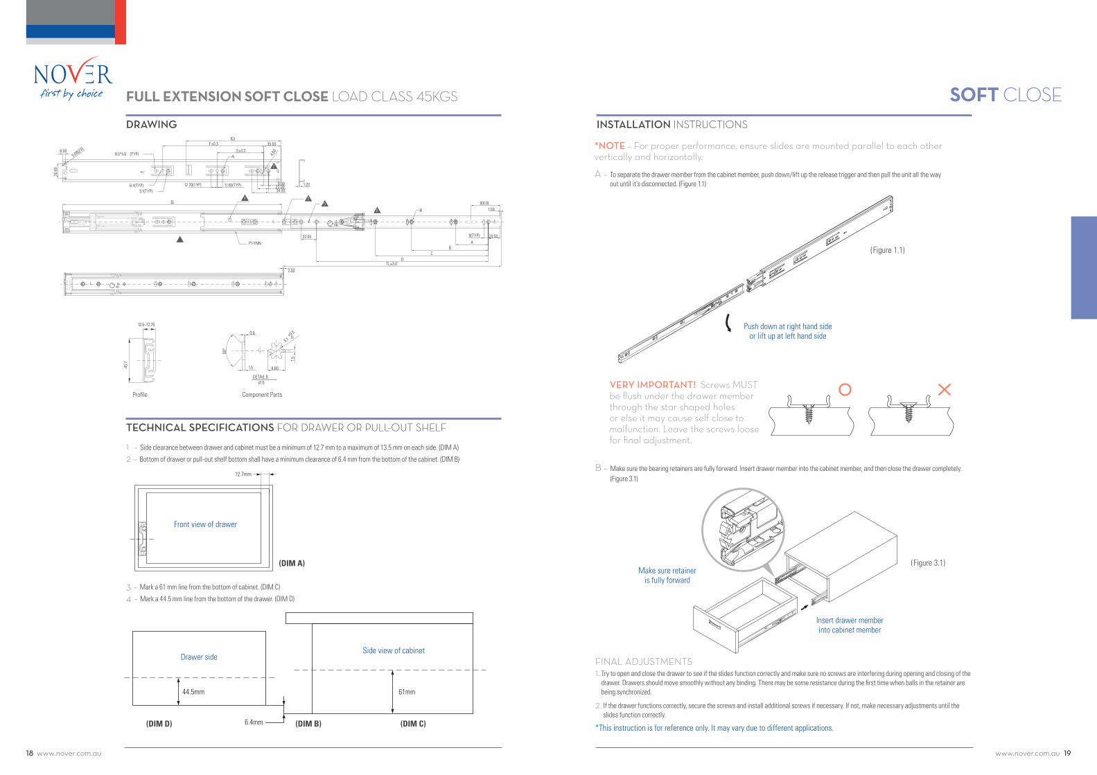
1 – Side clearance between drawer and cabinet must be a minimum of 12.7 mm to a maximum of 13.5 mm on each side. (DIM A)
2 – Bottom of drawer or pull-out shelf bottom shall have a minimum clearance of 6.4 mm from the bottom of the cabinet. (DIM B)
3 – Mark a 61 mm line from the bottom of cabinet. (DIM C)
4 – Mark a 44.5 mm line from the bottom of the drawer. (DIM D)
INSTALLATION INSTRUCTIONS
TECHNICAL SPECIFICATIONS FOR DRAWER OR PULL-OUT SHELF
12.7mm
(DIM A)
Front view of drawer
6.4mm
61mm44.5mm
(DIM B) (DIM C)(DIM D)
Drawer sideSide view of cabinet
*NOTE – For proper performance, ensure slides are mounted parallel to each other vertically and horizontally.
A – To separate the drawer member from the cabinet member, push down/lift up the release trigger and then pull the unit all the way out until it’s disconnected. (Figure 1.1)
*This instruction is for reference only. It may vary due to different applications.
FINAL ADJUSTMENTS1. Try to open and close the drawer to see if the slides function correctly and make sure no screws are interfering during opening and closing of the
drawer. Drawers should move smoothly without any binding. There may be some resistance during the first time when balls in the retainer are being synchronized.
2. If the drawer functions correctly, secure the screws and install additional screws if necessary. If not, make necessary adjustments until the slides function correctly.
B – Make sure the bearing retainers are fully forward. Insert drawer member into the cabinet member, and then close the drawer completely. (Figure 3.1)
Push down at right hand side or lift up at left hand side
(Figure 1.1)
Make sure retainer is fully forward
(Figure 3.1)
Insert drawer member into cabinet member
VERY IMPORTANT! Screws MUST be flush under the drawer member through the star shaped holes or else it may cause self close to malfunction. Leave the screws loose for final adjustment.
Component Parts
www.nover.com.au 2120 www.nover.com.au
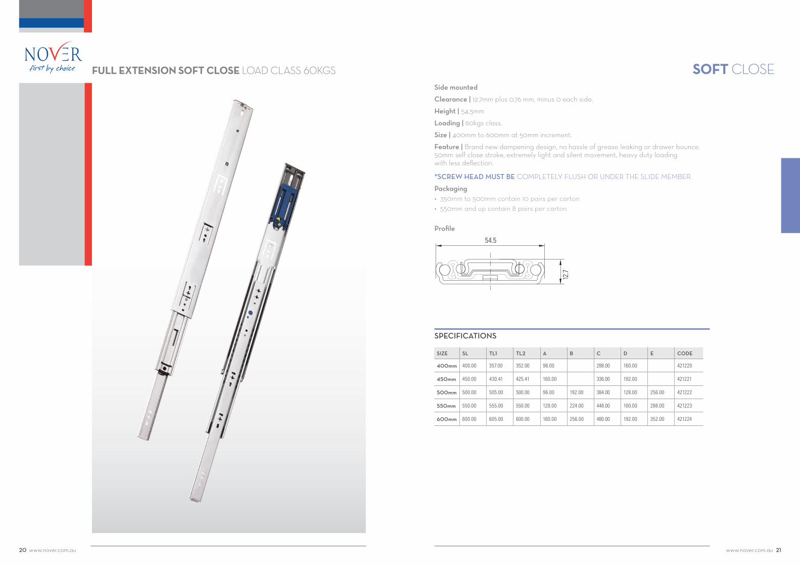
SOFT CLOSEFULL EXTENSION SOFT CLOSE LOAD CLASS 60KGSSide mounted
Clearance |12.7mmplus0.76mm,minus0eachside.
Height | 54.5mm
Loading |60kgsclass.
Size |400mmto600mmat50mmincrement.
Feature | Brand new dampening design, no hassle of grease leaking or drawer bounce. 50mmselfclosestroke,extremelylightandsilentmovement,heavydutyloading with less deflection.
*SCREW HEAD MUST BE COMPLETELY FLUSH OR UNDER THE SLIDE MEMBER.
Packaging• 350mmto500mmcontain10pairspercarton• 550mmandupcontain8pairspercarton
Profile
54.5
12.7
SPECIFICATIONS
SIZE SL TL1 TL2 A B C D E CODE
400mm 400.00 357.00 352.00 96.00 288.00 160.00 421220
450mm 450.00 430.41 425.41 160.00 336.00 192.00 421221
500mm 500.00 505.00 500.00 96.00 192.00 384.00 128.00 256.00 421222
550mm 550.00 555.00 550.00 128.00 224.00 448.00 160.00 288.00 421223
600mm 600.00 605.00 600.00 160.00 256.00 480.00 192.00 352.00 421224

www.nover.com.au 2322 www.nover.com.au
SOFT CLOSEDRAWING
FULL EXTENSION SOFT CLOSE LOAD CLASS 60KGS
1 – Drawer or pull-out shelf must be at least 13.0 mm narrower than cabinet opening on each side. (DIM A)
2 – Bottom of drawer or pull-out shelf bottom shall have 6.4 mm or 1/4” minimum clearance from the bottom of Cabinet. (DIM B)
3 – Mark a center line with proper height ( H ) from the bottom of cabinet. (DIM C)
4 – Mark a center line with proper height (H-6.4 mm) from the bottom of drawer. (DIM D)
INSTALLATION INSTRUCTIONS
TECHNICAL SPECIFICATIONS FOR DRAWER OR PULL-OUT SHELF
13mm~13.5mm
(DIM A)
6.4mm
HH-6.4mm
(DIM B) (DIM C)(DIM D)
6.00
30.0
0
11.90(TYP)15.70(TYP)
27.6040.30
35.10D
E
φ4.60
1
N
1.80
50.8016.00
TL 1± 3.00C
AB
9.40(TYP)
5.00
TL 2 ± 3.00
1.00
6.00
9.5X4.6 φ(TYP)
SL ± 0.25φ6.4(TYP)
φ5.1(TYP)
φ5.00(2X)
11.90
AP 2 - 0 58
A
15.80
1.80
CL
54.5
12.7
φ5.1
DETAIL A
2.0
+0. 5-0
CL 10.6
0.6
1.8
90°
Profile Component Parts
*NOTE – For proper performance, ensure slides are mounted parallel to each other vertically and horizontally.
A – To separate the drawer member from the cabinet member, push down/lift up the release trigger and then pull the unit all the way out until it’s disconnected. (Figure 1.1)
B – Fix the cabinet member through the star shaped holes for best performance. Leave the screws loose for final adjustment.
*This instruction is for reference only. It may vary due to different applications.
FINAL ADJUSTMENTS1. Try to open and close the drawer to see if the slides function correctly and make sure no screws are interfering during opening and closing of the
drawer. Drawers should move smoothly without any binding. There may be some resistance during the first time when balls in the retainer are being synchronized.
2. If the drawer functions correctly, secure the screws and install additional screws if necessary. If not, make necessary adjustments until the slides function correctly.
C – Make sure the bearing retainers are set to the front of the slides. Insert drawer member into the cabinet member and then push the drawer all the way in. Never use force when inserting the drawer. (Figure 3.1)
Push down at right hand side or lift up at left hand side
(Figure 1.1)
(Figure 3.1)
Insert drawer member into cabinet member
VERY IMPORTANT! Screws MUST be flush under the drawer member through the star shaped holes or else it may cause self close to malfunction. Leave the screws loose for final adjustment.
Make sure retainer is fully forward

www.nover.com.au 2524 www.nover.com.au
TOUCH TO OPENFULL EXTENSION TOUCH-TO-OPEN LOAD CLASS 45KGSSide mounted
Slide Clearance |12.7mmplus0.76mm,minus0eachside.
Height | 45.7mm
Loading | 45kgs class.
Size | 300mm to 700mm at 50mm increments.
Feature | New touch to open mechanism, 4mm activating stroke, almost 2/3 of drawer opening depending on installation and drawer loading.
Packaging• 300mmto450mmcontain15pairspercarton• 500mmandupcontain10pairspercarton
Profile
12.5
~12.
7
45.7
SIZE SL TL A B C D E CODE
300mm 301.0 304.8 96.0 LAB(2) 136.0 42041420
350mm 351.0 355.6 96.0 128.0 192.0 42041422
400mm 401.0 406.4 128.0 144.0 128.0 240.0 42041424
450mm 451.0 457.2 160.0 160.0 128.0 288.0 42041426
500mm 501.0 508.0 192.0 160.0 192.0 336.0 42041428
550mm 551.0 558.8 224.0 192.0 224.0 384.0 42041430
600mm 601.0 609.6 224.0 224.0 256.0 432.0 42041432
650mm 651.0 660.4 256.0 256.0 288.0 486.0 42041434
700mm 701.0 711.2 256.0 320.0 320.0 544.0 42041436
SPECIFICATIONS

www.nover.com.au 2726 www.nover.com.au
TOUCH TO OPEN
CL
36.1 CD
E
49.3
1.50
A B
LAB(2)=96.0
LAB(1)=137.5
SL
TL±3.0
φ4.6(TYP)
φ6.4(TYP)
9.5*φ4.6(TYP)
φ4.6*9.5(TYP) 9.5*φ4.6
(TYP)
Ø4.6(TYP)
11.4012.7011.40
12.70
8.9013.00
12.70
15.80(TYP)
9.40(TYP)
3.0
CL
CL
CL
CL
1
6
1
23
4
2
3
4
12.5~12.7
45.7
DRAWING
FULL EXTENSION TOUCH-TO-OPEN LOAD CLASS 45KGS
INSTALLATION INSTRUCTIONS
Profile
A – The actuating stroke of Repon touch to open is 4 mm, so please reserve at least 10 mm gap between the drawer back and cabinet back. (Figure 1.1)
B – The new Repon touch to open deliberately set the drawer member above the cabinet member by 6 mm in fully closed position to absorb installation tolerance. (Figure 1.2)
(Figure 1.2)
(Figure 1.1)
10mm
6mm
C – Please refer to the following drawings for the drawer member and cabinet member mounting position. (Figure 1.3) (Figure 1.4)
D – The actuating stroke of Repon touch to open is 4 mm, so please reserve at least 10 mm gap between the drawer back and cabinet back. (Figure 2.1)
10mm
(Figure 2.1)
Not use computer boring (use jig to position)
*Set drawer member back by 3 mm when use chusion.
(Figure 1.3)
Place drawer member against drawer front.
Set cabinet member flush with cabinet opening.
Using computer boring (32 mm system)
37mm
7mm
5mm
Set drawer member back by 5mm.
Use 1st hole 37mm far from the edge to fix the cabinet member.
*Set drawer member back by 8 mm when use chusion.
(Figure 1.4)
E – The new Repon touch to open deliberately set the drawer member above the cabinet member by 6mm in fully closed position to absorb installation tolerance.
F – Please refer to the following drawings for the drawer member and cabinet member mounting position.
6mm
D
Place drawer member against frawer front.
D = Drawer front thickness + 6mm
(Figure 2.2)
(Figure 2.3)
*This instruction is for reference only. It may vary due to different applications.

www.nover.com.au 2928 www.nover.com.au
STAINLESS STEEL SLIDESSide mounted
Slide Clearance |19.6mm
Height | 435.3mm
Loading |65kgsclass.
Size | 250mm to 700mm at 50mm increments.
Feature | Stainless steel slide channel ideal for higher moisture and salt dense environments. Packaging• 4pairspercarton
Profile
SPECIFICATIONS
SIZE SL TL A B C D CODE
400mm 16.0 16.39 9.87 14.25 14.75 421240
450mm 18.0 18.39 8.37 11.87 16.25 16.75 421241
500mm 20.0 20.39 9.37 13.87 18.25 18.75 421242
600mm 24.0 24.39 10.37 15.87 20.25 20.75 421243
700mm 28.0 28.39 13.37 21.87 26.25 26.75 421244
STAINLESS STEEL SLIDES LOAD CLASS 65KGS
0.77
1.38
Sorry the image is too low res. If you can get a high res
that would be great?
*Image shown not of actual slide

www.nover.com.au 3130 www.nover.com.au
STAINLESS STEEL SLIDESSTAINLESS STEEL SLIDES LOAD CLASS 68KGS
DRAWING
END VIEW
0.77
1.38
SL
D
C
B
TL±0.118
C
D
0.208XØ0.177(X4)
0.63
4.38
0.50
A
B
1.000.50
4.38
A0.63
0.208XØ0.177(X4)
Ø0.177X0.208(X4)
1
1
9
1.00
Ø0.177X0.208(X4)
9
Profile
1 – Drawer or pull-out shelf side clearance must be at least 19.6mm.
2 – Bottom of drawer or pull-out shelf bottom shall have 6.4 mm or 1/4” minimum clearance from the bottom of Cabinet. (DIM B)3 – Mark a center line with proper height ( H ) from the bottom of cabinet. (DIM C)
4 – Mark a center line with proper height (H-6.4 mm) from the bottom of drawer. (DIM D)
TECHNICAL SPECIFICATIONS FOR DRAWER OR PULL-OUT SHELF
(DIM B) (DIM C)(DIM D)
A – Align center line of cabinet member to pre-determined center line (H), and place lide 2mm backward from cabinet opening.
B – Fix the slides through the countersunk holes, and leave the screw loose for final adjustment. Move the slides back and forth, and make sure no screw is bound.
C – Align center line of drawer member to the pre-determined line (H-6.4mm), and place drawer member 2mm backwards from the drawer front or the pull-out shelf edge.
D – Fix the drawer member through vertical slots for vertical adjustment. Leave the screw loose for the final adjustment.
INSTALLATION INSTRUCTIONS
*This instruction is for reference only. It may vary due to different applications.
FINAL ADJUSTMENTS1. Try to open and close the drawer to see if the slides function correctly and make sure no screws are interfering during opening and closing of the
drawer. Drawers should move smoothly without any binding. There may be some resistance during the first time when balls in the retainer are being synchronized.
2. If the drawer functions correctly, secure the screws and install additional screws if necessary. If not, make necessary adjustments until the slides function correctly.

www.nover.com.au 3332 www.nover.com.au
POCKET DOOR SLIDESSide mounted
Slide Clearance | Minimum 1.5mm between door and cabinet.
Loading | 11 kgs class.
Size |350mmthrough650mmat50mmincrements.
Feature | Designed to use wooden follower strip. Anti-sagging support rollers. Doorhold-outfeature,maximumdoorheightisrecommendedto1200mm. Wooden follower strip and half overlay hinge is recommended.
Profile2
9.8
35.3
SPECIFICATIONS
SIZE SL TL A B C D E CODE
350mm 352.85 265.0 103.4 128.4 207.3 251.3 421200
400mm 403.65 315.8 103.4 179.2 258.1 302.1 421201
450mm 454.45 366.6 103.4 230.0 308.9 352.9 421202
500mm 505.25 417.4 103.4 280.8 359.7 403.7 421203
550mm 556.05 468.2 103.4 331.6 410.5 454.5 421204
600mm 606.85 519.0 103.4 382.4 461.3 505.3 421205
650mm 657.65 569.8 103.4 433.2 512.1 556.1 160.0 421206
POCKET DOOR LOAD CLASS 11 KGS

www.nover.com.au 3534 www.nover.com.au
POCKET DOOR SLIDESINSTALLATION INSTRUCTIONS
A – Place slides as Figure A, then mount the lower side slide down to the cabinet bottom.
B – DIM A1: Door thickness + 3 mm. Install pan head screws through horizontal slot holes for adjustment first, then screw the round hole for for fixing A.
A1
Follower strip
Bottom
(Figure A)
(Figure C)
C – Attach the door onto cabinet by hinges. ( Bought Separately )
TIPS ON DOOR GAP ADJUSTMENTS1 – For upper and lower gaps, please adjust mounting plate vertically. 2 – For door left or right door side gaps, please adjust C3.3 – Adjust C4 screw for door closure adjustment.
*NOTE – The above DIM. might vary due to different manufacture and hinge types.
C1
C2
DoorDoor guide roller assembly
Cabinet side panelslide
Door hinge
C3
C4
*This instruction is for reference only. It may vary due to different applications.
POCKET DOOR LOAD CLASS 11 KGS
DRAWING
TL±3.0
SLIDE LENGTH±0.25
31.55±0.3
21.6±0.3
4.6*5.3
25.4
9.5
6
10
M4(4X)
25.0
15.8
7.2 27.2
32.0
7
φ4.6
φ4 HOLEφ9-1mm Deep
4.6*9.5 9.5*4.65.3*4.5(TYP)
9.4
D±0.3
C±0.3
B±0.3
E±0.3
A±0.3
48.2
2 9.8
35.3
R L
Profile

NOVER & CO PTY LIMITED ABN 15 001 706 038
19 Wonderland Drive, Eastern Creek NSW 2766 Locked Bag 90, Wetherill Park Business Centre NSW 1851
t 1300 668 371 f 1300 668 372 e [email protected] w www.nover.com.au