report documentation page form approved · 40mm projects used by nato nations; ... incorporated...
TRANSCRIPT

REPORT DOCUMENTATION PAGE Form Approved
OMB No. 0704-0188 The public reporting burden for this collection of information is estimated to average 1 hour per response, including the time for reviewing instructions, searching existing data sources, gathering and maintaining the data needed, and completing and reviewing the collection of information. Send comments regarding this burden estimate or any other aspect of this collection of information, including suggestions for reducing this burden, to Department of Defense, Washington Headquarters Services, Directorate for information on Operations and Reports (0704-0188), 1215 Jefferson Davis Highway, Suite 1204, Arlington, VA 22202-4302. Respondents should be aware that notwithstanding any other provision of law, no person shall be subject to any penalty for failing to comply with a collection of information if it does not display a currently valid OMB control number. PLEASE DO NOT RETURN YOUR FORM TO THE ABOVE ADDRESS.
1. REPORT DATE (DD-MM-YYYY) 02-07-2013
2. REPORT TYPE
Final 3. DATES COVERED (From - To)
4. TITLE AND SUBTITLE Joint Ordnance Test Procedure (JOTP)-020 Safety and Suitability for Service Assessment Testing of Large Caliber Ammunition Greater Than 40MM
5a. CONTRACT NUMBER
5b. GRANT NUMBER
5c. PROGRAM ELEMENT NUMBER
6. AUTHORS
5d. PROJECT NUMBER
5e. TASK NUMBER
5f. WORK UNIT NUMBER
7. PERFORMING ORGANIZATION NAME(S) AND ADDRESS(ES) Range Infrastructure Division (CSTE-TM) US Army Test and Evaluation Command 2202 Aberdeen Boulevard Aberdeen Proving Ground, MD 21005-5001
8. PERFORMING ORGANIZATION REPORT NUMBER JOTP-020
9. SPONSORING/MONITORING AGENCY NAME(S) AND ADDRESS(ES) Range Infrastructure Division (CSTE-TM) US Army Test and Evaluation Command 2202 Aberdeen Boulevard Aberdeen Proving Ground, MD 21005-5001
10. SPONSOR/MONITOR’S ACRONYM(S)
11. SPONSOR/MONITOR’S REPORT NUMBER(S) Same as item 8
12. DISTRIBUTION/AVAILABILITY STATEMENT Distribution Statement A. Approved for public release; distribution is unlimited. 13. SUPPLEMENTARY NOTES Defense Technical Information Center (DTIC), AD No.: 14. ABSTRACT This Joint Ordnance Test Procedure (JOTP) shall serve as the US Joint Services Safety and Suitability for Service Test Procedures with regards to large caliber ammunition greater than 40 millimeters until which time the Allied Ammunition Safety And Suitability for Service Assessment Test Procedure (AAS3P-20) is approved by NATO Allied Committee 326 (AC326). Upon approval of the Allied Publication (AP), thorough review of this document shall be conducted with the intent to supersede. 15. SUBJECT TERMS joint service large caliber safety munitions LCEP ordnance
16. SECURITY CLASSIFICATION OF: 17. LIMITATION OF ABSTRACT SAR
18. NUMBER OF PAGES
140
19a. NAME OF RESPONSIBLE PERSON
a. REPORT B. ABSTRACT C. THIS PAGE
Unclassified Unclassified Unclassified 19b. TELEPHONE NUMBER (include area code)
Standard Form 298 (Rev. 8-98) Prescribed by ANSI Std. Z39-18

(This page is intentionally blank.)

DEPARTMENT OF DEFENSE
JOINT ORDNANCE TEST PROCEDURE (JOTP)-020
SAFETY AND SUITABILITY FOR SERVICE
ASSESSMENT TESTING OF LARGE CALIBER AMMUNITION GREATER THAN 40MM
Joint Services Munition Safety Test Working Group

(This page is intentionally blank.)

Joint Ordnance Test Procedure (JOTP)-020 Safety and Suitability for Service Assessment Testing of Large Caliber Ammunition Greater Than 40MM
DOCUMENT COMPLETION DATE: 2 July 2013
TITLE AND SUBTITLE: Joint Ordnance Test Procedure (JOTP)-020 Safety and Suitability for Service Assessment Testing of Large Caliber Ammunition Greater Than 40MM
PREPARING ACTIVITY: Range Infrastructure Division (CSTE-TM) US Army Test and Evaluation Command 2202 Aberdeen Boulevard Aberdeen Proving Ground, MD 21005-5001
SPONSORING ACTIVITY: Range Infrastructure Division (CSTE-TM) US Army Test and Evaluation Command 2202 Aberdeen Boulevard Aberdeen Proving Ground, MD 21005-5001
DISTRIBUTION STATEMENT: Distribution Statement A. Approved for public release; distribution is unlimited. ABSTRACT: Joint Ordnance Test Procedure (JOTP)-020 is intended to act as a munition type specific document dealing specifically with the necessary safety testing and assessments for large caliber ammunition greater than 40mm to enter service within the North Atlantic Treaty Organization (NATO) community. COORDINATION DRAFT REVIEWED BY: This document was coordinated with the following Standardization Offices: AR, AS, EA, MC, MI, NM, OS, TE, AF-11, and AF-99. In addition, the document was also coordinated with the Joint Weapon Safety Working Group, DODESB, OUSD LW&M, and select subject matter experts within the field of missile and rocket munitions safety testing. ASSIST COORDINATION DATE: 19 Feb 2013 with a 45-day coordination period. IMPLEMENTATION PLAN: This Joint Ordnance Test Procedure (JOTP) shall serve as the US Joint Services Safety and Suitability for Service Test Procedures with regards to large caliber ammunition greater than 40mm until which time the Allied Ammunition Safety And Suitability for Service Assessment Test Procedure (AAS3P-20) is approved by NATO Allied Committee 326 (AC326). Upon approval of the Allied Publication (AP), thorough review of this document shall be conducted with the intent to supersede. APPROVING AUTHORITY:
Deputy Director, Land Warfare & Munitions Office of the Under Secretary of Defense for Acquisition, Technology and Logistics

(This page is intentionally blank.)
DEPARTMENT OF DEFENSE
JOINT ORDNANCE TEST PROCEDURE *Joint Ordnance Test Procedure (JOTP)-020 2 July 2013 DTIC AD No.
SAFETY AND SUITABILITY FOR SERVICE ASSESSMENT TESTING OF LARGE CALIBER AMMUNITION GREATER THAN 40MM
Page Paragraph 1. INTRODUCTION ................................................................. 2 2. SCOPE ................................................................................... 2 2.1 Purpose .................................................................................. 2 2.2 Application ............................................................................ 3 2.3 Limitations ............................................................................. 3 3. DEFINITIONS ...................................................................... 3 4. FACILITIES AND INSTRUMENTATION ......................... 5 4.1 Facilities ................................................................................ 5 4.2 Instrumentation Accuracy and Calibration ............................ 5 5. LIFE CYCLE ENVIRONMENTAL PROFILE (LCEP) ...... 6 6. SAFETY TEST PLANNING ................................................ 6 6.1 Overall Test Objectives ......................................................... 6 6.2 Data Sources .......................................................................... 6 6.3 Test Tailoring ........................................................................ 7 6.4 Environmental Test Levels .................................................... 7 6.5 Test Outline ........................................................................... 8 6.6 Test Safety Considerations .................................................... 9 6.7 Test Sample Quantities .......................................................... 9 6.8 Munitions ............................................................................... 10 6.9 Weapon .................................................................................. 11 6.10 Test Controls ......................................................................... 11 7. PRE- AND POST-TEST INSPECTIONS ............................ 12 7.1 Initial (Baseline) .................................................................... 12 7.2 Level 1 (Basic) ...................................................................... 12 7.3 Level 2 (Intermediate) ........................................................... 13 7.4 Level 3 (Full) ......................................................................... 13 8. SAFETY AND SUITABILITY FOR SERVICE TEST PROGRAM OVERVIEW ..................................................... 13 8.1 Sequential Environment Tests (SET) .................................... 13 8.2 Non-Sequential Tests ............................................................ 14 9. ADDITIONAL TESTS AND ASSESSMENTS ................... 14 9.1 Munition Hazard Classification ............................................. 14
Approved for public release; distribution unlimited.

JOTP-020 2 July 2013
2
Page Paragraph 9.2 Insensitive Munitions Assessment ........................................ 14 9.3 Munition Software System Safety Assessment ..................... 14 9.4 Fuze Safety Testing ............................................................... 14 9.5 Electromagnetic Environmental Effects ................................ 15 9.6 Munition Demilitarization and Disposal Assessment Testing 15 9.7 Render Safe Procedure Testing ............................................. 15 9.8 Range Safety and Sustainability ............................................ 15 9.9 Explosive Materials Qualification Testing ............................ 15 9.10 Health Hazards Testing ......................................................... 16 10. MUNITION SAFETY DATA PACKAGE ........................... 16 APPENDIX A. BACKGROUND/RATIONALE ........................................... A-1 B. S3 TEST PROGRAM ........................................................... B-1 C. ENVIRONMENTAL TEST DESCRIPTIONS ..................... C-1 D. S3 NON-SEQUENTIAL/FIRING TEST .............................. D-1 E. LEVEL 3 INSPECTION - BREAKDOWN TEST AND CRITICAL ANALYSIS ........................................................ E-1 F. FACILITIES AND INSTRUMENTATION REQUIREMENTS ................................................................ F-1 G. ABBREVIATIONS / REFERENCES AND RELATED DOCUMENTS ...................................................................... G-1 1. INTRODUCTION. This Joint Ordnance Test Procedure (JOTP) is aimed at the Safety and Suitability for Service (S3) Assessment Testing for Large Caliber Ammunition Greater Than 40mm as agreed under North Atlantic Treaty Organization (NATO) Standardization Agreement (STANAG) 4629 and Allied Ammunition Safety and Suitability for Service Publication (AAS3P)-1. AAS3P-1 provides general discussion of S3 Assessment Testing. JOTP-020 is intended to act as a munition type specific document dealing specifically with the necessary safety testing and assessments for Large Caliber Ammunition Greater Than 40mm to enter service within the NATO community. This document was developed within the international community and is written with primarily references to NATO test procedures to provide a framework for international procurement and test programs. Table G2-1 (Appendix G, Annex 2) provides detailed comparison of similar national and international test standards. Whilst each test standard often has unique requirements, the table does not imply the standards are the same or interchangeable. However, national test standards, or test methods, may be substituted for the international test standard referenced in the JOTP. 2. SCOPE. 2.1 Purpose.
JOTP-020 2 July 2013
3
The purpose of this JOTP is to guide personnel involved in the planning and implementation of S3 assessment testing of munitions to enable collection of appropriate evidence covering the entire life cycle. The objective of the safety test program defined by this JOTP is to provide data to demonstrate that the munition will be “safe for use”, as defined in AAS3P-1, throughout the potential deployment possibilities in NATO service. 2.2 Application. The guidance provided in this JOTP is applicable to Large Caliber Ammunition Greater Than 40mm projects used by NATO Nations; multi-national munition projects as well as for National munition projects. The munitions covered by this JOTP include all munitions greater than 40mm for artillery, tank, and naval use. 2.3 Limitations. This JOTP is not intended to be used in the assessment of effectiveness, reliability, or performance of a munition unless failure to be reliable or to perform effectively is deemed to represent a direct and immediate safety hazard to the user or other personnel. However, the data may be used in support of effectiveness, reliability, or performance assessment. This JOTP is only applicable to Large Caliber Ammunition Greater Than 40mm. This document does not address fuze qualification. Guidance should be sought from Allied Ordnance Publication (AOP)-20 or National fuze standards. This document does not address Gun-Launched Guided Munitions (GLGM) or mortars. 3. DEFINITIONS. Definitions in this JOTP take precedence over those in AAS3P-1, until such time as they can be incorporated into AOP-38. Refer to AAS3P-1 for definitions related to Safety and Suitability for Service test procedures. 3.1 Projectile. An object, projected by an applied external force and continuing in motion by virtue of its own inertia, as a bullet, shell or grenade. 3.2 All-Up Round (AUR). A munition containing all tactical components including, for example, live energetic material, tactical electronics, and safe-and-arm devices. 3.3 Propelling Charge. A component of a munition that contains the energetic material that when ignited, the gases produced propel the projectile out the gun tube. 3.4 Temperature Conditioning.

JOTP-020 2 July 2013
4
Exposure of a munition to a thermal environment in preparation for a test event at a specified test temperature. 3.5 Pre-Stress. Exposure of a munition to a sequence of one or more environmental stresses (i.e., temperature, humidity, shock, vibration, etc.) prior to conducting a particular test event. 3.6 Solar Radiation Equivalent (SRE) Temperature. The maximum temperature value experienced by the energetic material (e.g., propellant, projectile, fuze) during the solar test. Determination of this value will require exposure of an inert, internally instrumented round, with similar thermal characteristics to the production munition, to the full solar test requirement in its packaged and unpackaged configurations as defined in Appendix C, Annex 1, paragraph C.1-6. 3.7 Temperature Stabilization. Temperature stabilization is achieved when the part of the munition considered to have the longest thermal lag is changing no more than 2 °Celsius (C) per hour. Since it may not be practical to monitor the part of a live round with the longest thermal lag during test without damaging seals, the stabilization time may be determined prior to live round testing using an inert, internally instrumented round, with similar thermal characteristics to the munition. The stabilization time will typically be required for the round in both the unpackaged and the transport configurations and at the hot and cold temperature extremes. 3.8 Lower Firing Temperature (LFT). The temperature to which test munitions are stabilized for cold test firing. This temperature is based on the climatic region that the testing nation and the using nations predict to be the worst case cold firing environment that the test munition will encounter during operations. 3.9 Lower Conditioning Temperature (LCT). The temperature to which test munitions are stabilized for cold non-firing tests. This temperature is based on the climatic region that the testing nation and the using nation predict to be the worst case cold environment that the test munition will encounter during storage and transportation. 3.10 Upper Firing Temperature (UFT). The temperature to which the test munitions are stabilized for hot test firing. This temperature is based on the climatic region that the testing nation and the using nations predict to be the worst case hot firing environment that the test munition will encounter during operations.
JOTP-020 2 July 2013
5
3.11 Upper Conditioning Temperature (UCT). The temperature to which test munitions are stabilized for hot non-firing tests. This temperature is based on the climatic region that the testing nation and the using nations predict to be the worst case hot environment that the test munition will encounter during storage and transportation. 3.12 Weapon System. A weapon and those components required for its operation, comprising the aggregate of the weapon, the associated launching vehicle or platform launching the munition, the available munitions, and the ancillary equipment necessary to test, aim, launch, and guide the munition, as applicable. 3.13 Gun Launched Guided Munitions (GLGM). Those kinds of gun munitions capable of deviating from their trajectory to anticipate or react to the target’s maneuvers or to reduce the miss distance to the target. When the rounds are in the gun tube they behave as conventional ones and when they are flying they behave like missiles: they can either follow a conventional trajectory or not. They could be spin stabilized or fin stabilized and they could either be rocket assisted or not. The mere application of a Course Corrected Fuze that cannot perform controlled munition guidance, onto a conventional projectile does not render the shell a GLGM. 4. FACILITIES AND INSTRUMENTATION. 4.1 Facilities. All test facilities utilized must suit specific test requirements and provide adequate protection for personnel and equipment in accordance with local and national regulations for testing of hazardous materiel. Note that although it is not necessary for all the facilities to be co-located, consideration should be given to the safe transport of potentially degraded test articles between test facilities. In addition to the requirements provided in Appendix F, Table F-1, test facilities shall be prepared for the handling and possible disposal of explosive munitions. 4.2 Instrumentation Accuracy and Calibration. The instruments and test equipment used to control or monitor the test parameters shall have an accuracy at least equal to 1/3 the tolerance of the variable to be measured. Recommended tolerances are provided in Appendix F, Table F-2. In the event of conflict between this accuracy and guidelines for accuracy in any one of the test procedure or methods referenced in this document, the more stringent accuracy requirement takes precedence. The instrumentation and test equipment shall be calibrated periodically to laboratory standards whose calibration is traceable to national laboratory standards. The test facility shall maintain the calibration records.
JOTP-020 2 July 2013
6
5. LIFE CYCLE ENVIRONMENTAL PROFILE (LCEP). a. Representative LCEPs for large caliber munitions are illustrated in Appendix B of this document as sequential test flow charts with test procedures provided in Appendix C and rationale provided in Appendix A. The representative LCEPs are based upon the applicable environmental factors for storage, transportation, and deployment selected from Annex A of Allied Environmental Conditions Test Publication (AECTP) 100, along with the generic usage profiles from Annex E of AECTP 100, for Artillery, Tank, Self-Propelled Gun, or Naval Gun munitions. Testing in accordance with this life cycle sequence and combining environments (e.g., vibration with temperature) is required to determine if the interaction (synergistic effect) and/or the sequence in which environments are experienced may result in a safety hazard. Deviations from these LCEPs contained in this document shall be approved by National S3 Authority(ies) or other appropriate Authorities prior to the start of testing. The rationale used in tailoring shall be documented and retained as part of the Munition Safety Data Package as noted in Annex C of AOP-15. b. LCEPs for each munition type are contained in Appendix B. For each LCEP there are two primary streams; one hot stream and one cold stream. c. If a safety related hazard is identified during any part of the test then failure analysis shall be conducted and corrective action taken. This may include redesign or additional testing. Significant hazard or amendment to the design may require a repeat of the full test sequence. 6. SAFETY TEST PLANNING. 6.1 Overall Test Objectives. The objectives of the safety tests are to provide data to demonstrate that the munition is “safe for use” as defined in AAS3P-1. To achieve this, the safety tests must provide data to determine the following: a. Existence and nature of actual and potential munition hazards to personnel and equipment. b. Safety of the munitions throughout the planned LCEP including storage, transport, maintenance, training, operations, firing, and disposal. 6.2 Data Sources. Safety assessment of munitions is an evolutionary process, which begins in the early design phase of the munition and continues after deployment of the munition. The data gathered during the S3 tests described in this document should not be considered the exclusive source of data to support the safety assessment. Other sources of safety data such as the ones described below shall be considered.
JOTP-020 2 July 2013
7
6.2.1 Design and Test Data Review. Review of existing safety, design, and test data is mandatory prior to development of the safety test plan. Review documentation concerning munition requirements, design, safety, and prior tests in order to identify potential hazards and their causes. The degree to which this JOTP is followed and the degree to which other data are accepted in place of these tests depends on the characteristics of the munition and on the credibility and completeness of existing safety data. These reviews, and this JOTP, must be used to develop the detailed safety test plan and shall be in accordance with National health and safety standards and regulations. Thoroughly review all data related to the munition under test. This review should include test data from component and munition level performance and safety testing (engineering-design or component-development tests). 6.2.2 Safety Assessment Report (SAR). A SAR is a formal document that summarizes potential hazards to developmental testers that shall be submitted by the material developer to the tester prior to commencement of testing. The SAR shall delineate the safety related characteristics of the munition, identify potential hazards, and assess severity and probability of the mishap risk of each identified hazard, and recommend procedures and precautions to mitigate hazards to an acceptable level of risk. 6.3 Test Tailoring. The safety tests recommended in this document are intentionally conservative to account for a wide range of deployment possibilities in NATO service. Test tailoring may be necessary for a variety of reasons including test conduct safety considerations, variation of deployment requirements and/or life cycle environmental profile, and the need to address nation specific requirements. When nation specific requirements conflict with requirements in this document, the reference tables in Appendix G may be used to assist in the process of cross-referencing the national and international documents. The rationale used in tailoring shall be documented and retained as part of the S3 assessment file. Particularly document the elimination of tests, reduction of sample quantities, or reduction of severities, any of which may result in reduced evidence to fully support the required safety assessment of the munition. Deviations from the S3 assessment testing program shall be approved by National S3 Authority(ies) or other appropriate Authorities prior to the start of testing. A tailoring example is provided in Appendix B, Annex 5 to show how test tailoring may be applied to an S3 Test Program based on a specific set of circumstances. 6.4 Environmental Test Levels. The environmental test levels specified in this document are based on the anticipated extreme conditions for storage, transportation, handling, maintenance, and firing or release of the munition. For deployment and aircraft related vibration and shock, the environments should be tailored based on measured data. Natural and induced environmental factors for storage and transportation were selected from AECTP 100, Annex A. Climatic test levels are based upon climatic categories defined in AECTP 230 and 300. Transportation dynamic test levels are based
JOTP-020 2 July 2013
8
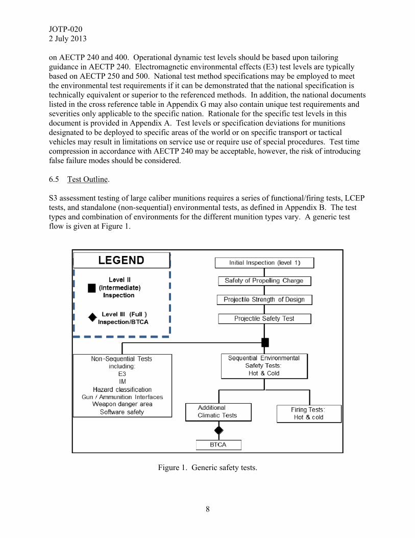
on AECTP 240 and 400. Operational dynamic test levels should be based upon tailoring guidance in AECTP 240. Electromagnetic environmental effects (E3) test levels are typically based on AECTP 250 and 500. National test method specifications may be employed to meet the environmental test requirements if it can be demonstrated that the national specification is technically equivalent or superior to the referenced methods. In addition, the national documents listed in the cross reference table in Appendix G may also contain unique test requirements and severities only applicable to the specific nation. Rationale for the specific test levels in this document is provided in Appendix A. Test levels or specification deviations for munitions designated to be deployed to specific areas of the world or on specific transport or tactical vehicles may result in limitations on service use or require use of special procedures. Test time compression in accordance with AECTP 240 may be acceptable, however, the risk of introducing false failure modes should be considered. 6.5 Test Outline. S3 assessment testing of large caliber munitions requires a series of functional/firing tests, LCEP tests, and standalone (non-sequential) environmental tests, as defined in Appendix B. The test types and combination of environments for the different munition types vary. A generic test flow is given at Figure 1.
Figure 1. Generic safety tests.
JOTP-020 2 July 2013
9
6.6 Test Safety Considerations. Explosive materials can often become less stable with age. This aging is exacerbated by the presence of increased temperature, humidity and vibration/mechanical stressing. It is therefore necessary to review the projected test sequence and determine whether the sequence, including any temperature conditioning and storage, result in an unacceptable hazard. As a minimum, this will require an assessment of explosive material stability with respect to extreme temperature exposure durations. It might be necessary to divide the overall test time (shock, vibration, and bounce in particular) into smaller portions to prevent heat build-up within the munition and subsequent unintended energetic reaction potential. It is essential and mandatory to have a log for each round indicating the amount of time that has been spent at extreme temperature for the entire test sequence, including all periods of temperature conditioning. 6.7 Test Sample Quantities. a. The test sample quantities are largely dictated by the minimum number of destructive tests (e.g., firings, breakdown test and critical analysis (BTCA), hazard classification, and insensitive munitions (IM)) to provide sufficient evidence of munition safety. Specific rationale for the quantities in each of the destructive test categories is provided in Appendix A. The following general notes should be considered when assessing the test sample quantities required for an S3 test program: (1) Materiel having more than one configuration or operating state and/or operating platform may require increased test sample quantities. (2) Existing safety data may also be reviewed for acceptability with the goal of reducing sample sizes and the number of tests. The degree to which this data can be used depends upon munition characteristics, reliability and completeness of the existing safety data, and the adequacy with which it treats hardware configuration, input stress, potential synergistic effects, types and severity of hazards, and the probability of hazard occurrences. However, tests which may interact with each other in a synergistic fashion (e.g., vibration/shock or vibration/climate) must not be removed from the sequence. (3) Additional munitions beyond those recommended in this document may be needed in the test program for baseline purposes and to replace munitions that become damaged during testing. Also, fully inert munitions may be required for testing to evaluate and certify test procedures. In addition, inert projectiles may be required for charge firing tests. (4) Completely functional munitions are only required for test assets designated for the munition level dynamic firing tests. For all other test assets, non-safety critical components may be removed in order to reduce test cost. Any hardware that is removed should be replaced by mass simulants with thermal, structural, and dynamic characteristics similar to the tactical hardware.

JOTP-020 2 July 2013
10
b. The total number of test munitions required for S3 assessment varies slightly according to the type of munition. The minimum total required numbers for each munition type are indicated in Appendix B. c. Tailoring of Test Sample Quantities. The test sample quantities or configuration may be modified provided rationale is approved by the appropriate National S3 Authority(ies) or other appropriate Authorities. 6.8 Munitions. 6.8.1 The projectile, cartridge or propelling charge under test may require support munitions to permit firing. Support munitions shall be currently fielded service munitions selected from single lots. If it is not possible to select all samples from a single lot, additional lots with the same components from the same manufacturing process and manufacturer may be used. Any fuze selected as a test component must be qualified for S3 in accordance with AOP-20 for the AUR chosen for test. 6.8.2 Evidence should be provided by the developing agency that the explosive and propellant used in the munition have been assessed and qualified. 6.8.3 Identify each component with a unique number to be used throughout testing. 6.8.4 Make pre-firing measurements of the munition, as required, and compare with drawing and specification requirements. 6.8.5 Visually inspect all munitions, components, and metal parts for damage, exudation, deterioration, and obvious manufacturing defects. Also visually inspect the packaging and munition markings to ensure they are in accordance with approved drawings and specifications/requirements. Replace missing or damaged packaging before vibration and rough handling tests on the munition. 6.8.6 Further inspect munitions for manufacturing defects using the non-destructive techniques (magnetic particle, ultrasonic, or fluorescent particle inspection). Note: Magnetic particle inspection should never be used on live munitions, unless there is proven assurance ahead of time that no hazard exists in doing so to the munitions in question. 6.8.7 Take radiographs of explosives, and compare to appropriate standards to determine if cracks, voids, and other explosive defects or unusual conditions are present which would contribute to a safety failure. Radiographs will be taken prior to the start of S3 testing and at inspection points defined in the applicable figure at Appendix B. Radiographs are required to examine metal parts for proper positioning and for cracks or damage and, to provide evidence that the fuze is in the unarmed (safe) position. For rough handling and transportation tests, radiograph the test munition before and after test. 6.8.8 Internal pressure gauges should not be inside cartridges that are to be subjected to vibration or rough handling due to the potential for damage to the propellant or primer.
JOTP-020 2 July 2013
11
6.8.9 When external (piezoelectric) pressure gauges are used with fixed or semi-fixed munitions, as in the measurement of differential pressure, prepare the cases by drilling holes through the case that corresponds to the location of each gauge against which the case is to be seated, in order to permit gas pressure to reach the gauges. Provide a positive indexing system on the cartridge case to ensure proper orientation of the case when it is loaded into the weapon. 6.9 Weapon. Select the weapon for which the munition is designed. If the munition is designed for more than one weapon (self-propelled, towed, with/without automatic loader -rammer, etc.), consider distributing the firings across all variations. Provision must be made to ensure that sufficient gun tubes with the required wear lives (where applicable) are available for the tests stated in Appendix D, Annex 5. 6.10 Test Controls. 6.10.1 Conduct all tests with the test munitions uniformly conditioned to the appropriate temperatures (UFT or LFT, see paragraphs 3.8 and 3.10). All temperature conditioning will be monitored by at least two independent measuring devices (e.g., conditioning-box measuring equipment, and separate thermocouples). 6.10.2 Review radiographs and inspection results for each round, prior to firing, for abnormalities which could cause malfunctions. Some of the shock, vibration, and rough-handling tests may damage the test munition. These munitions will be fired if it is judged by the tester that troops in the field would have overlooked or considered the damage negligible by superficial visual inspection and fired the munition. However, the design agency shall be consulted before firing any munition with abnormalities. If such a munition is not fired, it shall be considered to have failed that safety test phase. 6.10.3 Inspect the gun tube periodically throughout testing, in accordance with the guidance in International Test Operations Procedure (ITOP) 03-2-802A, and whenever there are unexpected occurrences such as projectile breakup, cartridge case rupture, or unexpectedly high chamber pressure. 6.10.4 For artillery, fire test projectiles to at least 75% of the maximum time of flight or range and at maximum propelling charge. This is to verify the safety of the projectile during long times of flight. 6.10.5 Propelling system safety tests should be conducted with rocket-assisted and base bleed projectiles with the motor “on” if these projectiles are standard for use with the propelling charge under test. Failure of rocket motor ignition can be caused by propelling-charge residue.
JOTP-020 2 July 2013
12
7. PRE- AND POST TEST EXAMINATIONS. Perform examinations of the munitions as indicated in the sequential test flowcharts in Appendix B. Examinations are to be conducted in accordance with the examination levels defined below. Perform the appropriate inspections, checks, or disassembly before and after any non-destructive munition S3 test and when test exposure is considered to have affected the test munition. Conduct radiographic and/or other non-destructive inspection of the test munition to ascertain and document any external and internal conditions existing prior to, or resulting from testing. Safety mechanisms and devices shall remain in their safe condition. Non-destructive techniques utilized shall have the capability to accurately assess condition of the safety critical characteristics. 7.1 Initial (Baseline). An initial inspection should be conducted to verify conformance of the munition to the build standard (see AAS3P-1) and to provide an assessment of the baseline condition for subsequent test inspections. In addition to the Level 1 and Level 2 examinations described in paragraphs 7.2 and 7.3, initial inspections should include baseline photographs and physical characteristics of the munition and packaging. Deviations from the build standard should be assessed by the appropriate authorities to determine that the asset(s) is satisfactory for the S3 test program. 7.2 Level 1 (Basic). Basic inspection consists of visual examination. Visually inspect all test munitions to determine the following as applicable: a. Condition of shipping container. (1) Physical damage. (2) State of pressurization and seals. (3) State of desiccant and humidity indicators. (4) State of munition retention hardware. (5) State of shock and temperature indicators. (6) Container markings. b. Condition of the munition. (1) Physical damage. (2) Indication of seepage, leaks, or explosive exudation or powdering.

JOTP-020 2 July 2013
13
(3) State of seals. (4) State of safe and arm (S&A) devices and fuzes. (5) Munition markings. 7.3 Level 2 (Intermediate). Level 2 inspection encompasses Level 1, but also consists of radiography and/or non-destructive examinations (e.g., ultrasonic, tomography, magna-flux, eddy-current, etc.) of all munitions. The examination facility should have the capability to conduct radiographic inspection at low temperature extremes or as soon as possible after removal from a cold conditioning chamber. Deviation from this should be recorded and accepted by the appropriate authority. Level 2 examinations should determine the following: a. State of Primers, Fuzes (and any other S&A devices if present) to ensure that the munition is safe for handling and continued testing. b. Testing of electrically initiated primers with a certified low current circuit tester or ohm-meter, and electronic fuzes with the appropriate fuze setter to ensure that the munition is safe for handling and continued testing. c. Indications of structural damage. d. Check for propellant cracking or breakup. Where practical, this examination should be conducted at the low operating temperature. e. Projectile damage, particularly shell filling damage (including base bleed, or following charge, damage), to examine cracks, voids, defective adhesion and exudation. Where practical, this examination should be conducted at the low operating temperature. f. Movement of internal components in the case of cargo projectiles. 7.4 Level 3 (Full). Level 3 inspection encompasses Levels 1 and 2, but also includes disassembly or internal examination (i.e., BTCA). This is typified by destructive examination assessing the chemical (composition, hazard properties, etc.) and physical (tensile, hardness, etc.) properties of not just the explosive materials, but also of other critical engineering materials contained within the test munition. Additional details are provided in Appendix E. 8 SAFETY AND SUITABILITY FOR SERVICE TEST PROGRAM OVERVIEW. 8.1 Sequential Environmental Tests (SET).
JOTP-020 2 July 2013
14
Test sequences for separate loading projectiles, propelling charges, and full cartridges (including projectile) are given in Appendix B. An attempt has been made to address all environments described in Annex A of AECTP 100, based on the representative LCEP for large caliber munitions greater than 40mm. Assessment tests use complete, live munitions except as noted in these procedures. Whenever possible, environmental test details are deferred to the STANAG 4370 AECTPs referenced in the sequential test procedures. Test methods which are not currently covered by STANAG or Allied Publication (AP) are referred to the appropriate national document or ITOP. Conflicts between the referenced test methods and the procedures described in this document should defer to the referenced test method. Background and rationale for these tests are provided in Appendix A, Annex 1. Test severities for these tests are provided in Appendix C. 8.2 Non-Sequential Tests. Appendixes C and D also provide descriptions of non-sequential tests on munitions separate from the sequential environmental tests. These are Life Cycle dependant. 9. ADDITIONAL TESTS AND ASSESSMENTS. Hazard Classification, IM Assessment, and Munition Software System Safety Assessments are required as part of the S3 package but the details regarding the series of tests required are not provided in this document since they are governed by other STANAGs. References to the governing STANAGs are provided. 9.1 Munition Hazard Classification. Appropriate munition hazard classification testing shall be conducted in accordance with STANAG 4123 and Allied Ammunition Storage and Transport Publication (AASTP)-3. 9.2 Insensitive Munitions Assessment. The IM assessment testing shall be conducted in accordance with STANAG 4439 and AOP-39. For a system expected to have significant changes to its vulnerability with age/use, using environmentally stressed munitions within IM vulnerability test and assessment should be considered. 9.3 Munition Software System Safety Assessment. Munition software shall be designed, assessed, and tested to assure its safety and suitability for service in accordance with AOP-52. 9.4 Fuze Safety Testing. a. JOTP-020 assumes that the fuze is already qualified and that no further testing is required, but attention is drawn to the fuze qualification documentation used by NATO. The

JOTP-020 2 July 2013
15
results of fuze qualification are to be provided within the Munition Safety Data Package if the fuze is integral to the shell. b. The central objective of S3 of Fuzing Systems is to confirm and document that the fuzing system is safe and performs as intended in all expected service environments. The design safety requirements standard is STANAG 4187 and the fuze procedures document is AOP-20. Test Requirements for S3 Assessment is STANAG 4157, which is based on the principles of AOP-15. 9.5 Electromagnetic Environmental Effects. E3 assessment testing shall be conducted in accordance with STANAG 4370, and AECTPs 250 and 500. This testing must address Hazards of Electromagnetic Radiation to Ordnance (HERO), Electromagnetic Compatibility, Electrostatic Discharge (ESD), and Lightning Tests that are required to demonstrate electrical safety. Expected test asset quantities are provided in Appendix B. General guidance is provided in Appendix A, Annex 4 (Background / Rationale), and Appendix C, Annex 3 (Test Descriptions). 9.6 Munition Demilitarization and Disposal Assessment Testing. Appropriate safety testing and analysis to assess the demilitarization and disposal qualities of a munition shall be required in accordance with STANAG 4518 or respective national requirements. 9.7 Render Safe Procedure Testing. Appropriate testing and analysis shall be performed to develop Explosive Ordnance Disposal render safe procedures for new munitions entering the inventory. 9.8 Range Safety and Sustainability. In accordance with AOP-15, appropriate testing and analysis shall be conducted to assess range safety and sustainability. The potential for individual and cumulative environmental effects of munitions use on operational ranges, i.e., the expected deposition of hazardous substances, pollutants and contaminants, or emerging contaminants should be assessed. Weapon Danger Area may also be a consideration (see Allied Range Safety Publication (ARSP)-1 for further guidance). 9.9 Explosive Materials Qualification Testing. All explosive materials in a munition shall undergo appropriate testing and assessment per STANAG 4170 and AOP-7 to determine whether each possesses properties which make it safe for consideration for use in its intended role.

JOTP-020 2 July 2013
16
9.10 Health Hazards Testing. Appendix D, Annex 7 describes the testing and analysis to assess potential health hazards posed by the elements or combinations present in munitions and by munitions use. 10. MUNITION SAFETY DATA PACKAGE. As stated in AAS3P-1, and Annex C of AOP-15, the results of the testing and assessments required in this document will be compiled into a Munition Safety Data Package for use by the appropriate S3 approving authority in determining the overall S3 for large caliber munitions.
JOTP-020 2 July 2013
A-1
APPENDIX A. BACKGROUND/RATIONALE. This document was developed within the international community and is written with primarily references to NATO test procedures to provide a framework for international procurement and test programs. Table G2-1 (Appendix G, Annex 2) provides detailed comparison of similar national and international test standards. Whilst each test standard often has unique requirements, the table does not imply the standards are the same or interchangeable. However, national test standards, or test methods, may be substituted for the international test standard referenced in the JOTP. A1. INTRODUCTION. This appendix provides background information and rationale for the sample quantities and test environments recommended by this document. Formal safety testing is required to establish test data, which supports the issuance of the safety certification. The tests may indicate that limitations or restrictions must be imposed when the safety certification is issued. These restrictions may be imposed to limit exposure to certain environments (climatic, dynamic, electromagnetic, etc.), to restrict methods of transportation, or to define special handling and operating procedures. Generally, because of increased severity associated with safety testing, satisfactory performance of the test munition is not required. Poor performance after exposure to test environments may indicate a need for further investigation. A2. SAMPLE QUANTITIES AND STATISTICAL CONSIDERATIONS. The sample size recommendations of this document are based on prior tests of similar weapons and munitions, rather than strictly statistical considerations. Serious hazards such as in-bore functioning, or propellant cook-off, are observed as binary (pass or fail) events, but the parameters that cause these events are unlikely to be so. For a simple binomial assessment, the predicted low failure rate coupled with a requirement for high statistical confidence, the sample sizes become very large, sometimes in excess of the eventual service population. This is not practical. Therefore, other approaches are required in combination with statistical methods to estimate the residual safety margin based on measured parameters. For sequential environmental testing, confidence is built by ensuring the test environment provides the maximum feasible cumulative stress to the test munitions. Statistical methods are used to derive the test severities to ensure as far as practicable they envelope the predicted environment. However, as stated above, the final test quantities presented in this document are a compromise based upon the experience of a large international community of subject matter experts. A2.1 Performance Test Data. Successful performance tests (component and munition level) with and without environmental exposure add confidence to the safety of the munition. Utilization of these data effectively increases the total number of samples.

JOTP-020 2 July 2013
A-2
APPENDIX A. BACKGROUND/RATIONALE. A2.2 Increased-Severity Testing. In order to yield acceptable confidence in safety test results with a relatively small sample size, increased-severity testing is prescribed in this document. The probability of munition failure resulting in a hazardous condition is increased by testing under conditions which are representative of credible extremes or slightly above the environments to be encountered in actual munition use. These extreme environments are low-probability environments. Therefore, the test levels recommended in this document are at credible extremes. Rationale for the specific environments is presented in Annex 1 of this appendix. A2.3 Sequential and Combined Environments. Munitions are subjected to environmental testing in a sequential manner, which is representative of the probable LCEP scenario. Testing in accordance with this life cycle sequence and combining environments (e.g., vibration with temperature) is recommended to determine if the interaction (synergistic effect) and/or the sequence in which environments are experienced may result in a safety hazard. A2.4 Inspection For Incipient Failure. For each test sample which fails during test, there may be many that nearly fail. Detailed inspection of the test munitions before, during, and after test adds significantly to the confidence of the test data given the limited sample size. Radiographic inspections provide particularly useful insight into the condition of the munition including early detection of displaced components as well as cracking or de-bonding of energetic materials. It is recommended the munition be conditioned to LCT (in such a manner that thermal shock is not introduced) for the radiographic inspection to enhance cracks in the energetic materials and provide for easier detection of defects. Depending on the assessed likely failure modes, ambient may be sufficient. If the inspections indicate that failure is likely to occur or nearly occurred, further investigation or testing may be required. If the inspections indicate that a margin of safety exists and that no safety hazard is likely to occur, additional confidence in the data is gained. A2.5 Variable Test Data. The use of measured variable data (pressure, force, etc.) is recommended whenever practical. If margins of safety can be demonstrated between measured test data and measured or analytical failure modes, confidence in the test results are enhanced. If measured variable data indicate only small margins of safety exist, further investigation or testing may be required.

JOTP-020 2 July 2013
A-3
APPENDIX A. BACKGROUND/RATIONALE. ANNEX 1. BACKGROUND/RATIONALE FOR ENVIRONMENTAL TESTS.
A.1-1 GENERAL. A.1-1.1 Life Cycle Environmental Profile. During its expected life cycle, a munition will experience transportation from its place of manufacture to a storage facility, transportation to a place of temporary storage in an Operational Theatre, before tactical transportation within that Operational Theatre, and finally, function or return to storage. At each stage it will experience exposure to various environments resulting from the local climate, general rough handling, and transportation by numerous platforms. It may also experience abnormal environments such as being accidentally dropped. A.1-1.2 Test Levels. This annex gives rationale for the specific test procedures and test severities recommended in this document. The test levels are credible extreme environments, to which the munition may be exposed as part of the LCEP. Conflicts between the recommended test levels and munition specific LCEP environments should be addressed through test tailoring and/or safety release restrictions. A.1-1.3 Temperatures. Munitions are required to remain safe and suitable for service at extremes of temperature where personnel are expected to be capable of military operations, namely within NATO climate categories C2 to A1. It would be expected for the munitions to remain S3 during and following storage and transportation by various platforms within these climate categories. The extreme temperatures of these climate categories (or the SRE for hot stream munitions) form the basis for the conditioning temperatures for all mechanical environment tests intended to address logistic movements. Munitions are also expected to remain S3 following storage at extreme cold conditions of a C3 climate category, but would not necessarily be expected to be moved during the coldest period within this climate zone due to difficulties with vehicles and the temperatures being outside the human comfort zone (i.e. survival as opposed to capable of military operations). For this reason, the cold temperature extreme for mechanical environmental tests have been based on the C2 climate category. Default steady state conditioning temperatures to be used for each climate category if no additional data is readily available are shown in Table A1-1.

JOTP-020 2 July 2013
A-4
APPENDIX A. BACKGROUND/RATIONALE. ANNEX 1. BACKGROUND/RATIONALE FOR ENVIRONMENTAL TESTS.
TABLE A1-1. CLIMATIC CATEGORY TEMPERATURES
CLIMATIC
CATEGORY STORAGE TEMPERATURE
CONDITIONING LIMITS (ºC) FIRING TEMPERATURE (ºC)
(see Note 2) A1/B3 71 63 A2/B2 63 56
A3 58 52 C0 -21 -19 C1 -33 -32 C2 -46 -46 C3 -51 -51 M1 69 49 M2 63 Not Known M3 -34 -18
NOTES: (1) Temperatures listed are for steady state conditioning.
(2) Firing temperature relates to firing a munition that has been protected from direct solar exposure. If it has been determined that a potential exists for direct exposure to solar radiation, then it is highly recommended that a solar radiation test be conducted to establish the maximum response temperature. This value should be used as the UFT.
(3) Prior to using this table, evaluate the safe operating temperatures of the energetic
materials, as table temperatures may exceed the safe operating conditions of these energetic materials.
(4) The moderating effects of shipboard storage vary widely depending on position within the
ship, type of ship, and climate control, therefore, the firing temperatures given above for M1, M2, and M3 are merely an example of what may be expected at the extremes on board ship.
A.1-1.4 Temperature Stabilization. For environmental tests that require temperature conditioning, temperature stabilization is achieved when the part of the munition considered to have the longest thermal lag is changing no more than 2 °C per hour. Since it may not be practical to monitor the interior parts of a live munition with the longest thermal lag during test without damaging seals, the stabilization time may be determined prior to live munition testing using an instrumented thermally equivalent inert munition. The stabilization time will typically be required for the munition in both the unpackaged and the transport configurations and at the hot and cold temperature extremes. As an alternative, a default duration of 24 hours for unpackaged, 48 hours for packaged, or up to a maximum of 72 hours for palletized may be applied after the chamber air around the test article has stabilized to the test temperature. Care should be taken that no munition exceeds the safe life of the energetic material when subjected to multiple exposures to high temperature conditioning.

JOTP-020 2 July 2013
A-5
APPENDIX A. BACKGROUND/RATIONALE. ANNEX 1. BACKGROUND/RATIONALE FOR ENVIRONMENTAL TESTS.
A.1-1.5 Solar Radiation Equivalent Temperature. As an alternative to installing solar lamps in a test chamber, the SRE temperature is specified in most mechanical environment tests in order to facilitate testing. The SRE is the maximum temperature value experienced by the energetic material (e.g., propellant, warhead main charge) after exposure to direct or indirect solar radiation. Determination of this value will require exposure of an inert, internally instrumented munition, with similar thermal characteristics to the munition, to the full solar test requirement defined in Appendix C, Annex 1, paragraph C.1-6. The SRE temperature should be determined for both the packaged and unpackaged state, and applied for all mechanical environment tests such that the packaged SRE is used for packaged tests and the unpackaged SRE for the unpackaged tests. In the absence of this data, a value of 71 °C should be used in lieu of the SRE temperature since this reflects the maximum value of the A1 Storage and Transit diurnal cycle defined in AECTP 230 Leaflet 2310/1. A.1-2. CLIMATIC ENVIRONMENT TESTS. The rationale for the climatic exposure tests are provided below. If only one test configuration is to be used this must be the most severe configuration, packaged or unpackaged, for the munition. In most, but not all, cases this is more likely to be the unpackaged configuration. A.1-2.1 High Humidity Cycling. The humid heat cycling test is performed to determine the resistance of materiel to the effects of a warm humid atmosphere. Moisture can alter burning characteristics of propellants or create excessive smoldering residue on combustible cartridge cases. High humidity may promote corrosion degradation. Also, moisture can enter the interface between the penetrator and sabot in Kinetic Energy (KE) tank cartridges resulting in difficulty in loading the munition into the chamber. Materiel may be exposed to this environment year-round in tropical areas and seasonally in mid-latitude areas. The procedure recommended by this document is an aggravated test. It does not reproduce naturally occurring or service-induced temperature-humidity scenarios. In order to reduce the time and cost of testing, the test munition is exposed to higher temperature and humidity levels than those found in nature; however, the exposure duration is shorter. A minimum of ten test cycles has proven to be effective at inducing degradation/failures that are indicative of long-term effects. For test munitions incorporating seals which protect moisture sensitive materials, longer test durations may be required to obtain a higher degree of confidence that the munition will remain S3 in warm-humid conditions. A.1-2.2 Temperature Storage And Cycling. a. High and low temperature diurnal cycling is carried as part of the sequential trials program in order to induce thermo-mechanical stressing and accelerated aging in the test munition. For most systems, 28 days hot and 3 days cold storage is considered sufficient to induce thermo-mechanical stressing representative of that which could occur in service. This

JOTP-020 2 July 2013
A-6
APPENDIX A. BACKGROUND/RATIONALE. ANNEX 1. BACKGROUND/RATIONALE FOR ENVIRONMENTAL TESTS.
duration has historically provided sufficient confidence for initial deployment of at least 3 months tactical storage. b. For gun ammunition, it is recommended that more thermal aging activity is undertaken. It is considered that a total of 56 days high temperature A1 cycling should be sufficient for the early signs of degradation to become apparent (based on a fall-back model assuming an activation energy of 70 kJ/mol). This allows an initial assessment to be made of potential failure modes and for adjustments to be made to the ageing model if necessary. c. Based on an Arrhenius kinetic model (discussed in AECTP 300 Method 306, paragraph 2.4.2 ‘Test Duration’) of 70 kJ/mol activation energy, a 9 day constant temperature storage test at 71 °C may be considered a suitable substitute for 28 days of the 56 days of high temperature cycle. This 9 day constant temperature addresses the deep storage element of the service life provided the 28 days of cycling is conducted to cover the direct exposure to the A1 induced environment. The 28 day minimum is because fixed temperature aging assessments will not take account of the thermo-mechanical stressing. In addition, it should be noted that laboratory based aging tests on small samples of energetic material do not take account of the geometry of the component, and so some potential failure modes could be missed. Whatever aging tests are conducted as part of the sequential trials program, the resulting predictions must be compared with the results of surveillance to determine how accurate they were and whether any potential failure modes were missed. A.1-2.2.1 Low-Temperature Storage. The low-temperature storage test is intended to determine the effects of low-temperature storage on the munition. There is a 1 percent probability that materiel deployed in arctic areas (Category C3, AECTP 200) will be exposed to a temperature of -51 °C. Category C3 applies to the coldest area of the North American continent and the areas surrounding the coldest parts of Siberia and Greenland. The low temperature can be expected to dwell once reached with no solar heating effects. A minimum of 3 days is recommended since this is considered sufficient duration to thermally stabilize the munition. If the munition under test could be susceptible to low temperature fluctuations, then the C2 cycle or that defined in the LCEP should be used. A.1-2.2.2 Low-Temperature Cycling. The low-temperature cycling test is intended to determine the effects of low-temperature operational environments on the munition (storage at extreme cold is addressed by the cold temperature storage test). The temperatures associated with the low-temperature cycling test are created by meteorological air temperatures (note that at this temperature extreme, the meteorological and induced diurnal cycles become aligned). The induced air temperature diurnal cycle (C2) for Category C storage and transit conditions given in AECTP 200 Leaflet 2310/1, Annex A, Table 4, is considered to adequately encompass most conceivable situations.
JOTP-020 2 July 2013
A-7
APPENDIX A. BACKGROUND/RATIONALE. ANNEX 1. BACKGROUND/RATIONALE FOR ENVIRONMENTAL TESTS.
A.1-2.2.3 High-Temperature Storage. a. The high-temperature storage test is intended to accelerate chemical based degradation mechanisms via a period of testing using a constant elevated temperature. A constant temperature of 71 °C is the maximum temperature that should be considered since this reflects the peak temperatures likely to be encountered during field storage or full solar exposure. Alternatively, a constant temperature of 58 °C may be more appropriate where the use of 71 °C is thought to generate unrealistic degradation (e.g., for nitro-cellulose + nitro-glycerine based propellants). b. Nine days of testing at 71 °C has been calculated (using the Arrhenius relationship) to give a similar degree of chemical degradation to that expected for 28 A1 ‘Storage and Transit’ temperature cycles using an assumed activation energy of 70 kJ/mol for the degradation mechanism. The 58 °C temperature will require a longer test duration of 22 days. Conditioning time for mechanical environmental tests should not be counted since this is effectively a thermal ramp and it can prove difficult to determine the amount of thermal energy input to the munition, and hence difficult to model the equivalent thermal degradation likely to have occurred within the munition. c. Great care is required when using this test as it may induce unrepresentative failure modes or may not adequately exercise potential failure modes. Consideration must be given to the design of the munition and any design limitations. For example, gas cracking, phase changes, or changes in the chemical reaction mechanism can occur during constant temperature aging, which may not occur during diurnal cycling or in service. This test should not be conducted instead of high temperature cycling, but may be used to supplement the chemical ageing effects of diurnal cycling tests. If the munition under test could be susceptible to high temperature fluctuations, then the A1 storage and transit (induced) cycle or that defined in the LCEP should be used. A.1-2.2.4 High-Temperature Cycling. The high-temperature cycling test is intended to determine the effects of high- temperature storage and operational environments on the munition. The temperatures associated with the high-temperature cycling test are created by meteorological air temperatures combined with solar radiation. The induced air temperature diurnal cycle for Category A1 storage and transit conditions given in AECTP 200 Leaflet 2310/1, Annex A, Table 1 is considered to adequately encompass most conceivable situations. For other environments, such as Naval controlled environments, other storage categories may be considered.
JOTP-020 2 July 2013
A-8
APPENDIX A. BACKGROUND/RATIONALE. ANNEX 1. BACKGROUND/RATIONALE FOR ENVIRONMENTAL TESTS.
A.1-2.3 Solar Radiation. The solar radiation test is intended to aggravate those thermally induced degradation mechanisms associated with elevated skin temperatures and thermal gradients within the munition, that are induced due to solar radiation. Since most Nations’ solar test chambers do not incorporate the ultraviolet element of the spectrum they tend not to aggravate the photo-chemical (actinic) degradation modes associated with solar radiation. If this is of concern (as may be the case for some paints, adhesives and polymers) then a separate ultra-violet exposure test will also be required. A minimum of seven A1 climate category cycles (meteorological temperature and solar radiation) is recommended in order to attain the maximum elevated temperatures throughout the test munition. The solar radiation level of 1120 W/m² is derived from AECTP 200. It should be noted that for Naval ammunition which is stored in a temperature conditioned compartment, solar radiation exposure is highly unlikely. A.1-2.4 Thermal Shock. a. The low-temperature shock test simulates movement of warm munitions from storage or from a transport vehicle to an extreme cold environment or vice versa. The low-temperature shock test consists of five temperature shock cycles between the temperatures of 21 °C and -51 °C. In most applications, the munition will be exposed to the temperature shock environment in its logistic container. (1) The -51 °C temperature is the low extreme presented in AECTP 200, for Climate Category C3. (2) Stabilization at the temperature extremes is required. Munitions in storage or in warm buildings would likely achieve temperature stabilization. Also, the extremely low temperatures encountered in the natural environment are likely to persist longer than the munition temperature stabilization time. b. The high-temperature shock test simulates either rapid ascent from a desert airfield to high altitude (e.g., 8 kilometer (km)) in an unheated aircraft compartment, and/or air drop from high altitude (8 km) to a desert environment. The low temperature shock test consists of five temperature shock cycles between the temperatures -5 °C and the unpackaged SRE temperature. In most applications, the munition will be exposed to the temperature shock environment in its logistic container. (1) The -5 °C temperature reflects that expected at an altitude of 8 km, from AECTP 230 Leaflet 2311/2, Table 3.
JOTP-020 2 July 2013
A-9
APPENDIX A. BACKGROUND/RATIONALE. ANNEX 1. BACKGROUND/RATIONALE FOR ENVIRONMENTAL TESTS.
(2) Stabilization at the temperature extremes is required. Munitions in flight prior to air delivery would likely achieve temperature stabilization. Also, the extremely high temperatures encountered in the natural environment are likely to persist longer than the munition temperature stabilization time. A.1-2.5 Immersion. The test (AECTP 300, Method 307) determines whether water is likely to penetrate seals/gaskets, affect materials, and/or affect performance of the munition during temporary immersion. Temperature conditioning the munition to 27 °C above the water temperature represents exposure to solar heating immediately prior to immersion, and induces a slight negative pressure differential within the munition (on cooling) to aggravate potential water ingress. Thirty minutes of immersion at a depth of one meter is required. It should be noted that this test is not required for Naval ammunition and some tank ammunition because it is not likely to be exposed to this environment, except in an accident scenario whereupon the munitions would not be expected to be fired. A.1-2.6 Salt Fog. a. The salt fog test (AECTP 300, Method 309) provides a set of repeatable conditions to determine the relative resistance of the munition to the effects of an aqueous salt atmosphere. This test helps to identify potential degradation mechanisms within a relatively short period of time, and is required for munitions/components that will experience exposure to high levels of salt in the atmosphere. It should be noted that testing at the component level will not address galvanic corrosion. b. As a minimum, this JOTP requires alternating wet-dry-wet-dry conditions of 24 hours each to be imposed. Alternating periods of salt fog exposure and drying conditions provides a higher damage potential than does continuous exposure to a salt atmosphere. The munition should be tested in the most severe configuration; that is, outside its shipping/storage container. The number of cycles may be increased if a higher degree of confidence is required to assess the ability of the materials involved to withstand a corrosive environment. Note, there is no relationship between this test and any real world exposure duration but it does provide an indication of potential degradation mechanisms associated with the salt (maritime) environment, nearby water sources, and from salted roads during winter operations. A.1-2.7 Sand and Dust. a. The sand and dust test (AECTP 300, Method 313, Procedures I and II) determines the effects on munitions after exposure to dust and sand atmospheres. It should be noted that this test is not required for Naval ammunition because it is not likely to be exposed to this environment.

JOTP-020 2 July 2013
A-10
APPENDIX A. BACKGROUND/RATIONALE. ANNEX 1. BACKGROUND/RATIONALE FOR ENVIRONMENTAL TESTS.
b. Munitions may be exposed to sand and dust environments on a worldwide basis. The greatest exposure would be expected during operations in desert regions due to vehicle convoys and aircraft/helicopter movements. The movement of military vehicles in hot dry desert regions or in areas where the surface is liable to break up into small particulate is liable to result in dust and sand-laden atmospheres. Material deposited inside the munition may cause short-circuiting, build-up of static electricity, and interference between moving parts. This JOTP requires the munition to be tested in the most severe configuration; that is outside of its shipping/storage container, using the most severe exposure parameters defined in Procedures I and II of Method 313. A.1-2.8 Rain/Watertightness. The rain test (AECTP 300, Method 310, Procedure I, Part 3) recommends using a 100±20 mm/hr severity for a duration of two hours, which is consistent with Part 3 of Method 310, Procedure 1. This is considered adequate to address exposure throughout most of the world apart from tropical zones where rainfall rates can be much higher. If deployment to tropical zones is anticipated then the munition should probably be subjected to the higher severity of 200±50 mm/hr. However, it should also be considered whether the munition will actually be fielded during a tropical rainstorm. If not then the ‘typical’ worldwide severity would be adequate. This JOTP requires the munition to be tested in the most severe configuration; that is outside of its shipping/storage container. A.1-2.9 Icing. Munitions are likely to be exposed to severe icing in cold climates. The icing test (AECTP 300, Method 311) determines the potential damaging effects of icing on the munition where stresses are imposed at joints and interfaces of adjacent parts. Damage may also be incurred as a result of the methods used to remove the ice and the subsequent accumulation of moisture after melting of the ice. The principal sources of ice are frosting, freezing rain, refreezing of thawing snow, and freezing of condensation. The thickness of the ice deposited on the munition depends upon the duration of the exposure and the contours of the munition. If the LCEP identifies icing as a threat to the munition, then medium ice loading conditions are required by this JOTP with the munition being in the most severe configuration; that is, outside of its shipping/storage container. A.1-2.10 Mold/Fungus. Microbial deterioration is a function of temperature and humidity and is an inseparable condition of hot-humid tropics and the mid-latitudes. AECTP 300, Method 308 is used to determine if mold growth will occur and, if so, how it may degrade/impact the use of the munition. Twenty-eight days is the minimum test period to allow for mould germination, breakdown of carbon-containing molecules, and degradation of material. This is a non-sequential test and may be conducted on leftover components or material samples.
JOTP-020 2 July 2013
A-11
APPENDIX A. BACKGROUND/RATIONALE. ANNEX 1. BACKGROUND/RATIONALE FOR ENVIRONMENTAL TESTS.
A.1-2.11 Contamination By Fluids. Contamination of the munition may arise from exposure to fuels, hydraulic fluids, lubricating oils, solvents and cleaning fluids, de-icing and anti-freeze fluids, insecticides, sun-block, disinfectants, coolant dielectric fluid, and fire extinguishants. Select the fluids most commonly encountered throughout the munitions life cycle and apply to the unpackaged munition per AECTP 300, Method 314 using the intermittent exposure method. Contamination effects must be analyzed for its immediate or potential (long term) effects on the safety of the munition. A.1-2.12 Cargo Aircraft Decompression. Rapid decompression can result when cabin pressurization is lost during an accident scenario in a transport aircraft. For large caliber gun ammunition, such loss of pressurization primarily affects fuzes and seals. This test should be conducted using packaged munitions to verify that the packaging does not present a secondary hazard to the munition or aircraft crew. An initial cargo compartment pressurization of 60 kPa is sufficient to address most common military transport aircraft worldwide. A.1-3. MECHANICAL ENVIRONMENT TESTS. a. This section provides the rationale for the dynamic environments likely to result from normal usage in typical environmental conditions, or from plausible mishandling during logistic and field operations. The AURs should be tested following temperature conditioning at either the SRE temperature (packaged or unpackaged as appropriate for the test configuration) for the hot AURs and -46 °C for the cold AURs (rationale given at Annex 1, paragraph A.1-1.3). b. A list of all potential LCEP components is shown below. (1) Logistic Transport. (a) Commercial. 1 Wheeled - Commercial Carrier. 2 Rail. 3 Cargo Ship. (b) Military Transport. 1 Wheeled (Composite Wheeled Vehicle or Two Wheeled Trailer).
JOTP-020 2 July 2013
A-12
APPENDIX A. BACKGROUND/RATIONALE. ANNEX 1. BACKGROUND/RATIONALE FOR ENVIRONMENTAL TESTS.
2 Tracked (if required). 3 Air (could potentially be Military or commercial air). 4 Naval Ship. (2) Tactical - Combat Platform (highly tailored - platform specific). (a) Wheeled. (b) Tracked. (c) Air (rotary or fixed wing). (d) Naval Ship. A.1-3.1 Logistic Transport Dynamics (Commercial). A.1-3.1.1 Logistic Wheeled Vehicle Transportation Dynamics. The movement of palletized materiel from the point of manufacture to the storage location is usually accomplished by commercial logistic vehicles over improved or paved highways. This can be addressed by the ‘Ground Wheeled Common Carrier’ vibration profiles in AECTP 400, Method 401. No factors of safety need to be applied to the amplitude since AECTP 400 vibration schedules are specified, that have been developed from field data and have conservatism factors built into them. Common Carrier vibration should be applied for a duration equivalent to the distances specified in AECTP 100 for Commercial Land Vehicles in the Transportation Mode. This is the first test to be performed in the large caliber munition life cycle test sequences of Appendix B. A.1-3.1.2 Logistic Rail Transportation Dynamics. a. Rail Transport vibration testing is not normally considered necessary as this environment has been assessed to be relatively benign compared to other vibration environments. If required, Rail Vibration testing should be conducted in accordance with AECTP 400, Method 401, Annex E. b. Rail impact testing (AECTP 400, Method 416) may be a requirement for military transportation certification in the US.
JOTP-020 2 July 2013
A-13
APPENDIX A. BACKGROUND/RATIONALE. ANNEX 1. BACKGROUND/RATIONALE FOR ENVIRONMENTAL TESTS.
A.1-3.1.3 Sea Transportation Dynamics. a. For transportation of materiel by commercial (or military) ships, vibration testing is not normally required since this environment tends to be relatively benign compared to other vibration environments within the LCEP. If specific Ship Vibration testing is considered necessary, this should be conducted in accordance with AECTP 400, Method 401, Annex E using the distances specified in AECTP 100 for Cargo Ships in the Transportation Mode. b. The shocks that are likely during non-contact underwater explosion (UNDEX) cause significant shock amplitudes that exceed those from normal handling. UNDEX shock testing in accordance with AECTP 400, Method 419 or appropriate National Standards is a mandatory requirement prior to ship embarkation for some NATO Nations and cannot be tailored out. The overall basis for UNDEX shock is addressed in Allied Navy Engineering Publication (ANEP) 43. Additional guidance may be found in STANAGs 4549 and 4150. The temperature in the ship’s hold would be expected to be relatively benign, so testing may be performed under standard ambient conditions (21 °C). The typical requirement would be for the munitions to remain ‘Safe for Disposal’ so testing may be conducted non-sequentially. If, however, the requirement is for the munitions to remain ‘Safe for Use’ (as may be necessary for Naval ammunition) UNDEX shock testing must be conducted within the sequence. A.1-3.1.4 Packaged Transit Drop. The Transit Drop test (AECTP 400, Method 414) simulates accidental drops encountered in logistical (packaged) handling of the munitions such as a hovering helicopter dropping the munitions from a sling or the unloading of munitions stacked on a truck. The recommended drop height of 2.1 meters is based on the likelihood of a munition being dropped from the bed of a transport vehicle. Tailoring may be carried out in accordance with the LCEP requirements. However, the drop test height should be no less than 1.5 meters. A.1-3.1.5 12- Meter Logistic Safety Drop Test. This mandatory logistic safety drop test, as described in STANAG 4375, assesses the safety of the munition when exposed to a free-fall drop which may be encountered during ship loading operations. This test is conducted as a non-sequential test since it is representing an accident scenario. A.1-3.2 Military Tactical Transport Dynamics. Military Transportation can be subdivided to address Military Logistic and Tactical ammunition movements. The former addresses logistic movement from a point of entry into theatre of operations to a field storage site. The latter addresses movement from the storage site to the firing platform, although it should be noted that that ammunition for a towed gun will not be
JOTP-020 2 July 2013
A-14
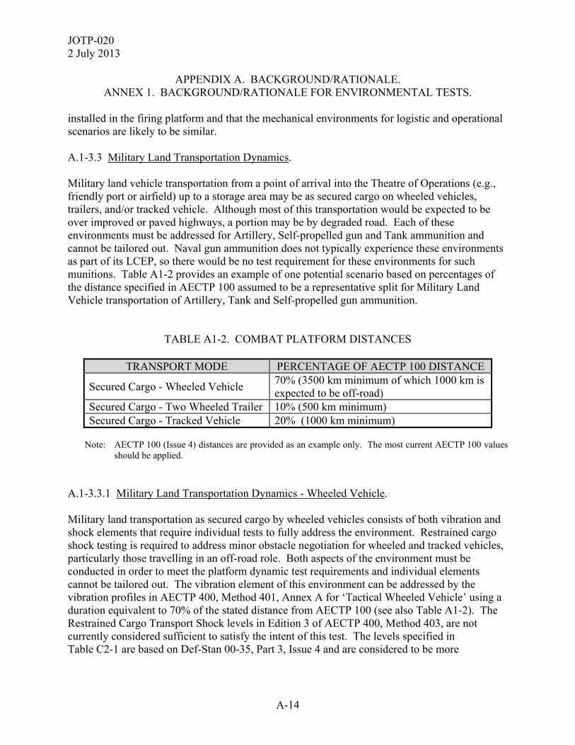
APPENDIX A. BACKGROUND/RATIONALE. ANNEX 1. BACKGROUND/RATIONALE FOR ENVIRONMENTAL TESTS.
installed in the firing platform and that the mechanical environments for logistic and operational scenarios are likely to be similar. A.1-3.3 Military Land Transportation Dynamics. Military land vehicle transportation from a point of arrival into the Theatre of Operations (e.g., friendly port or airfield) up to a storage area may be as secured cargo on wheeled vehicles, trailers, and/or tracked vehicle. Although most of this transportation would be expected to be over improved or paved highways, a portion may be by degraded road. Each of these environments must be addressed for Artillery, Self-propelled gun and Tank ammunition and cannot be tailored out. Naval gun ammunition does not typically experience these environments as part of its LCEP, so there would be no test requirement for these environments for such munitions. Table A1-2 provides an example of one potential scenario based on percentages of the distance specified in AECTP 100 assumed to be a representative split for Military Land Vehicle transportation of Artillery, Tank and Self-propelled gun ammunition.
TABLE A1-2. COMBAT PLATFORM DISTANCES
TRANSPORT MODE PERCENTAGE OF AECTP 100 DISTANCE
Secured Cargo - Wheeled Vehicle 70% (3500 km minimum of which 1000 km is expected to be off-road)
Secured Cargo - Two Wheeled Trailer 10% (500 km minimum) Secured Cargo - Tracked Vehicle 20% (1000 km minimum)
Note: AECTP 100 (Issue 4) distances are provided as an example only. The most current AECTP 100 values
should be applied. A.1-3.3.1 Military Land Transportation Dynamics - Wheeled Vehicle. Military land transportation as secured cargo by wheeled vehicles consists of both vibration and shock elements that require individual tests to fully address the environment. Restrained cargo shock testing is required to address minor obstacle negotiation for wheeled and tracked vehicles, particularly those travelling in an off-road role. Both aspects of the environment must be conducted in order to meet the platform dynamic test requirements and individual elements cannot be tailored out. The vibration element of this environment can be addressed by the vibration profiles in AECTP 400, Method 401, Annex A for ‘Tactical Wheeled Vehicle’ using a duration equivalent to 70% of the stated distance from AECTP 100 (see also Table A1-2). The Restrained Cargo Transport Shock levels in Edition 3 of AECTP 400, Method 403, are not currently considered sufficient to satisfy the intent of this test. The levels specified in Table C2-1 are based on Def-Stan 00-35, Part 3, Issue 4 and are considered to be more
JOTP-020 2 July 2013
A-15
APPENDIX A. BACKGROUND/RATIONALE. ANNEX 1. BACKGROUND/RATIONALE FOR ENVIRONMENTAL TESTS.
representative of the actual field levels. The number of shocks specified in Table C2-1 represents those typical for 1000 km of transportation. A.1-3.3.2 Military Land Transportation Dynamics - Trailer. Military land transportation within a trailer can be addressed by the vibration profiles in AECTP 400, Method 401, Annex A for ‘Two Wheeled Trailer’ using a duration equivalent to 10% of the stated distance from AECTP 100 (see also Table A1-2). A.1-3.3.3 Military Land Transportation Dynamics - Tracked. Military land transportation as secured cargo by tracked vehicles can be addressed by the vibration profiles in AECTP 400, Method 401, Annex B for ‘Materiel transported as Secure Cargo’ using a duration equivalent to 20% of the stated distance from AECTP 100 (see also Table A1-2). Typically, the shock aspects associated with this environment are addressed by other tests in the sequence so there is no requirement to address these specifically. A.1-3.3.4 Military Land Transportation Dynamics - Loose Cargo. For some Nations it is common to transport as limited quantity or ‘ready use’ ammunition in the towing vehicle as loose cargo. This requires specific testing within the environmental sequence in accordance with AECTP 400, Method 406, Procedure I or II depending upon whether the ammunition in its tactical packaging is likely to slide or roll. Since no overall distance is specified in AECTP 100, the default of 20 minutes testing as per AECTP 400, Method 406 is sufficient for most applications. A.1-3.4 Military Sea Transportation Dynamics. The dynamic environment for sea transportation by military vessels does not differ significantly from that for commercial shipping so no additional specific testing is required for military transport ships provided the testing identified at paragraph A.1-3.1.3 is addressed. A.1-3.5 Military Air Transportation Dynamics. Ammunition may be subjected to Military Air transportation by either fixed wing transport aircraft (jet and propeller) or helicopters. Distances for each mode of transport are specified in AECTP 100. Each of these environments must be addressed as applicable. Occasionally, Artillery and Self-propelled gun ammunition may also be resupplied by parachute, whilst all ammunition types may be subjected to under-slung movement in a tactical scenario.
JOTP-020 2 July 2013
A-16
APPENDIX A. BACKGROUND/RATIONALE. ANNEX 1. BACKGROUND/RATIONALE FOR ENVIRONMENTAL TESTS.
A.1-3.5.1 Military Air Transportation Dynamics - Jet Aircraft Vibration. The vibration environment associated with cruise is largely addressed by other vibration environments within the LCEP and need not necessarily be tested. The take-off vibration environment is significantly more severe than that for cruise, and can be addressed by the vibration profiles in AECTP 400, Method 401, Annex C for ‘Jet Aircraft Cargo - Takeoff’. The duration of this test is determined based on the number of takeoff events. The number of takeoff events in the life of gun ammunition may be estimated from the total flight duration defined in AECTP 100, Annex E, Appendix 1, for each commodity type transported by ‘Jet Aircraft’ divided by an assumed average flight duration of 10 hours per flight. A.1-3.5.2 Military Air Transportation Dynamics - Fixed Wing Propeller Aircraft Vibration. The most common propeller cargo aircraft used throughout NATO is the C130, of which the four and six bladed propeller variants are most typical (4-blade, f0=68 Hertz (Hz) and 6-blade, f0=102 Hz). The vibration severities for these aircraft are defined in AECTP 400, Method 401, Annex C, for ‘Propeller Aircraft’. If other cargo aircraft are identified as part of the LCEP, then the blade frequencies (f0) for these shall also require consideration. Since it is not always possible to predetermine the specific aircraft types that will be used during transportation, the total test duration based on the total flight duration defined in AECTP 100, Annex E, Appendix 1 for each commodity type transported by ‘Propeller Aircraft’ should be split between the different blade frequencies (f0) identified. For C130, this will require the test to be divided equally between the two blade frequencies (f0=68 Hz and 102 Hz) as a minimum. A.1-3.5.3 Military Air Transportation Dynamics - Helicopter Vibration. Gun launched ammunition may be transported by a variety of helicopters as part of its LCEP. Some of the more common helicopter types used throughout NATO with a cargo capacity can be grouped according to their fundamental blade frequencies as per Table A1-3. The vibration environment for these cargo helicopters can be addressed by the vibration profiles in AECTP 400, Method 401, Annex D for ‘Helicopter Cargo’. If other cargo helicopters are identified as part of the LCEP, then the blade frequencies (f1) for these shall also require consideration, but only if they are sufficiently different to the 11 Hz and 17 Hz already identified. Since it is not always possible to predetermine the specific aircraft types that will be used during transportation, the total test duration based on the total flight duration defined in AECTP 100, Annex E, Appendix 1 for each commodity type transported by ‘Helicopter’ should be split between the different helicopter types identified. For those identified in Table A1-3, this will require the test to be divided equally between the stated blade frequencies.
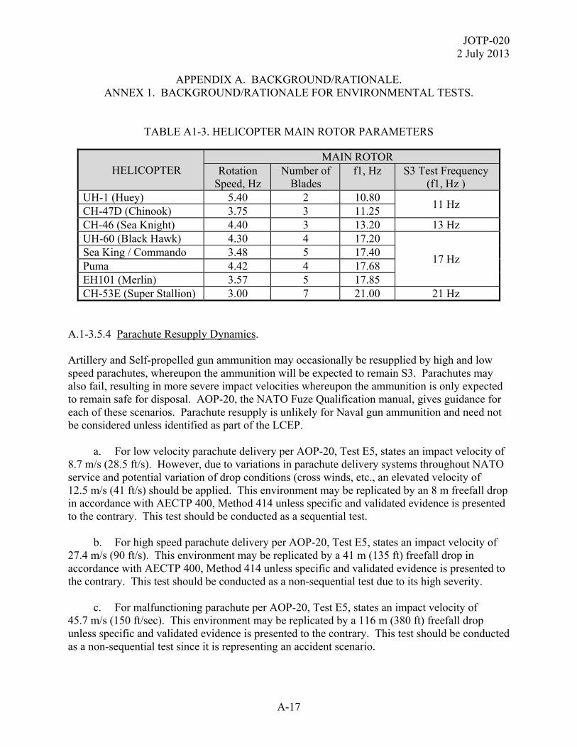
JOTP-020 2 July 2013
A-17
APPENDIX A. BACKGROUND/RATIONALE. ANNEX 1. BACKGROUND/RATIONALE FOR ENVIRONMENTAL TESTS.
TABLE A1-3. HELICOPTER MAIN ROTOR PARAMETERS
HELICOPTER MAIN ROTOR
Rotation Speed, Hz
Number of Blades
f1, Hz S3 Test Frequency (f1, Hz )
UH-1 (Huey) 5.40 2 10.80 11 Hz
CH-47D (Chinook) 3.75 3 11.25 CH-46 (Sea Knight) 4.40 3 13.20 13 Hz UH-60 (Black Hawk) 4.30 4 17.20
17 Hz Sea King / Commando 3.48 5 17.40 Puma 4.42 4 17.68 EH101 (Merlin) 3.57 5 17.85 CH-53E (Super Stallion) 3.00 7 21.00 21 Hz
A.1-3.5.4 Parachute Resupply Dynamics. Artillery and Self-propelled gun ammunition may occasionally be resupplied by high and low speed parachutes, whereupon the ammunition will be expected to remain S3. Parachutes may also fail, resulting in more severe impact velocities whereupon the ammunition is only expected to remain safe for disposal. AOP-20, the NATO Fuze Qualification manual, gives guidance for each of these scenarios. Parachute resupply is unlikely for Naval gun ammunition and need not be considered unless identified as part of the LCEP. a. For low velocity parachute delivery per AOP-20, Test E5, states an impact velocity of 8.7 m/s (28.5 ft/s). However, due to variations in parachute delivery systems throughout NATO service and potential variation of drop conditions (cross winds, etc., an elevated velocity of 12.5 m/s (41 ft/s) should be applied. This environment may be replicated by an 8 m freefall drop in accordance with AECTP 400, Method 414 unless specific and validated evidence is presented to the contrary. This test should be conducted as a sequential test. b. For high speed parachute delivery per AOP-20, Test E5, states an impact velocity of 27.4 m/s (90 ft/s). This environment may be replicated by a 41 m (135 ft) freefall drop in accordance with AECTP 400, Method 414 unless specific and validated evidence is presented to the contrary. This test should be conducted as a non-sequential test due to its high severity. c. For malfunctioning parachute per AOP-20, Test E5, states an impact velocity of 45.7 m/s (150 ft/sec). This environment may be replicated by a 116 m (380 ft) freefall drop unless specific and validated evidence is presented to the contrary. This test should be conducted as a non-sequential test since it is representing an accident scenario.
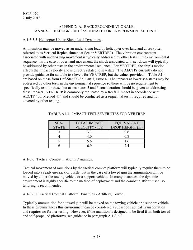
JOTP-020 2 July 2013
A-18
APPENDIX A. BACKGROUND/RATIONALE. ANNEX 1. BACKGROUND/RATIONALE FOR ENVIRONMENTAL TESTS.
A.1-3.5.5 Helicopter Under-Slung Load Dynamics. Ammunition may be moved as an under-slung load by helicopter over land and at sea (often referred to as Vertical Replenishment at Sea or VERTREP). The vibration environment associated with under-slung movement is typically addressed by other tests in the environmental sequence. In the case of over land movement, the shock associated with set-down will typically be addressed by other tests in the environmental sequence. For VERTREP, the ship’s motion affects the impact velocity and is directly related to sea-state. The AECTPs currently do not provide guidance for suitable test levels for VERTREP, but the values provided in Table A1-4 are based on those from Def-Stan 00-35, Part 3, Issue 4. The impacts at lower sea-states may be addressed by other tests in the environmental sequence so there will be no requirement to specifically test for these, but at sea-states 5 and 6 consideration should be given to addressing these impacts. VERTREP is commonly replicated by a freefall impact in accordance with AECTP 400, Method 414 and should be conducted as a sequential test if required and not covered by other testing.
TABLE A1-4. IMPACT TEST SEVERITIES FOR VERTREP
SEA-STATE
TOTAL IMPACT VELOCITY (m/s)
EQUIVALENT DROP HEIGHT (m)
3 3.3 0.6 4 4.0 0.8 5 5.6 1.6 6 6.9 2.4
A.1-3.6 Tactical Combat Platform Dynamics. Tactical movement of munitions by the tactical combat platform will typically require them to be loaded into a ready-use rack or bustle, but in the case of a towed gun the ammunition will be moved by either the towing vehicle or a support vehicle. In many instances, the dynamic environment is highly specific to the method of deployment and the combat platform used, so tailoring is recommended. A.1-3.6.1 Tactical Combat Platform Dynamics - Artillery, Towed. Typically ammunition for a towed gun will be moved on the towing vehicle or a support vehicle. In these circumstances this environment can be considered a subset of Tactical Transportation and requires no further testing. However, if the munition is designed to be fired from both towed and self-propelled platforms, see guidance in paragraph A.1-3.6.2.
JOTP-020 2 July 2013
A-19
APPENDIX A. BACKGROUND/RATIONALE. ANNEX 1. BACKGROUND/RATIONALE FOR ENVIRONMENTAL TESTS.
A.1-3.6.2 Tactical Combat Platform Dynamics - Tank and Self-Propelled Gun. Tailoring of the vibration and shock environment based on measured data for all storage locations is required although AECTP 400, Method 401, Annex B gives generic default vibration spectra for ‘Materiel In Turret Bustle Rack Or Installed In Turret’ and for ‘Heavy Vehicle - Materiel On Sponson Or Installed In Hull’. Some Nations may hold ammunition stocks in more than one location so the total distance stated in AECTP 100 for the ‘Combat Platform’ should be divided equally between the two tests identified above. When using default test severities, shocks other than those generated by auto-loaders are assumed to be addressed by other tests in the environmental sequence. A.1-3.6.3 Tactical Combat Platform Dynamics - Naval Gun. Although the sea transportation vibration environment is relatively benign and requires no specific testing, testing to address the combat platform environment is required due to the duration of exposure. Tailoring of the vibration and shock environment based on measured data is recommended although AECTP 400, Method 401, Annex E gives generic default vibration spectra for ‘Surface Ships, Minesweeper Size And Above’. This should be applied for the default duration of one hour per axis. Sea slamming dynamics are not addressed in the AECTPs so this should be addressed in accordance with National policy. A.1-3.6.4 Unpackaged Drop Tests. The Unpackaged Drop test simulates accidental drops encountered during handling of bare munitions, for example during resupply operations. The drop heights used will be LCEP specific. Minimum drop height is 1.5 m for all munitions (to represent manual handling), and the munition should remain safe to fire after dropping. In addition, you should consider other drop heights to verify that the ammunition will be safe to dispose if dropped during loading into the Combat Platform. If ammunition subjected to this test is damaged to such an extent that it cannot be fired and the damage does not create a hazardous condition, it should be tested at lower drop heights to determine the height for all drop orientations at which the ammunition shows no evidence of physical damage. A.1-3.6.5 Autoloader Cycling Test. When ammunition will be used with an automatic loader or ammunition handling mechanism, the accelerations, shocks, vibrations, and other stresses imposed on the ammunition must be measured and a tailored test severity defined. As an alternative, test ammunition may be cycled through the ammunition handling system and/or autoloader (load-extract testing).

JOTP-020 2 July 2013
A-20
APPENDIX A. BACKGROUND/RATIONALE. ANNEX 2. BACKGROUND/RATIONALE FOR FIRING TESTS.
A.2-1. INTRODUCTION. a. Every gun system is essentially a pressure vessel. As such it is necessary to demonstrate that the system can hold and vent the pressurised propelling charge gasses, and launch the projectile as intended, without presenting a hazard to personnel or platform. This is demonstrated through a number of firing tests conducted under various conditions to establish the safe operating pressures for the system. STANAG 4110 defines the pressure terms used for Cannon and outlines the methods employed in assessing those pressures. Figure A2-1 gives a graphical interpretation of the pressure terms for gun tubes and projectiles, with their approximate interrelationships in accordance with STANAG 4110.
Figure A2-1. Pressure Terms.
Charge Related Terms Projectile Related Terms
EMOP
MOP
ESCP
Pressure
PSMP
PDP (1)
PPMP
ESCP
MOP
EMOP
Cold
3sd
1.75sd Ideally 1.75sd (2)
1.75sd
3sd
Key:
EMOP = Extreme Maximum Operating Pressure
MOP = Maximum Operating Pressure
ESCP = Extreme Service Conditions Pressure
PSMP = Projectile Safe Maximum Pressure
PDP = Projectile Design Pressure
PPMP = Projectile Permissible Maximum Pressure MCP = Minimum Charge Pressure (for stickers) sd = Standard Deviation of ESCP Notes: 1. PDP may be equal to, but no less than EMOP. 2. Ideally PPMP should be 1.75sd lower than PDP and
represents the minimum projectile Proof Pressure. STANAG 4110 permits slight reduction of PMP to accommodate a lower Proof Pressure but this erodes the margin of safety for the projectile. PDP cannot be moved.
3. System DP and PMP are the lesser of the gun DP and PMP,
or the corresponding projectile DP and PMP. System DP may be equal to but not less than EMOP.
4. This diagram assumes a conventional propellant pressure
profile. For surface moderated or ballistic modified propellants, the temperature at which the risk of exceeding the design limits for the projectile may not be the highest temperature. However, the basic principle remains that the probability of exceeding the design pressure of the projectile should not be greater than one in a million.
MCP
3sd
Hot
Margin of Safety
JOTP-020 2 July 2013
A-21
APPENDIX A. BACKGROUND/RATIONALE. ANNEX 2. BACKGROUND/RATIONALE FOR FIRING TESTS.
b. This JOTP is only concerned with the ammunition and therefore assumes that the gun tube, breech, and other system components already have established safety and suitability criteria. In order to carry out a safety and suitability for service evaluation for the ammunition during launch there must already be Gun System Design Pressure (GDP) and Gun System Permissible Maximum Pressure (GPMP) limits available. The Gun System pressure limits may have been determined in parallel with a particular ammunition design. However, in many cases, several ammunition systems may be developed for a single gun. It is important to keep a distinction between the gun system pressure limits and the ammunition system pressure limits. In all cases the ammunition limits must be at, or preferably below, the gun limits. c. Gun system wear or fatigue profiles and the Cannon Safe Maximum Pressure Curve (STANAG 4110) shall also be performed to determine when and where maximum pressure occurs and to identify appropriate gun tubes for testing. A.2-2. SAFETY EVALUATION OF PROJECTILES. A.2-2.1 Projectile Pressure Limits. a. With the ammunition it is necessary to establish similar pressure limits for the projectile to those established for the gun system. The values for Projectile Design Pressure (PDP) and Projectile Permissible Maximum Pressure (PPMP) will have been established during design and development. b. The Projectile Strength of Design Test and the Projectile Safety in Gun Test, outlined in Appendix D have been developed to provide the minimum required evidence that the design actually meets the established values. A.2-2.2 Projectile Strength of Design Test. The Projectile Strength of Design Test has been developed to demonstrate for all projectiles that component casings and structures will not permanently deform or break up under the stresses induced between PPMP and PDP. For the purpose of this test, projectiles developed with energetic or hazardous fill shall be tested with inert fills. a. The trial is to determine the strength of the projectile at maximum firing stresses. Therefore, it is important to avoid firing rounds that are inherently stronger than the average population. It is recommended that effort is made to select weak projectiles (e.g., minimum metal). However, the critical requirement for the projectiles is that they represent the whole population of manufactured projectiles and that sufficient measurements are taken to ensure they represent that population.
JOTP-020 2 July 2013
A-22
APPENDIX A. BACKGROUND/RATIONALE. ANNEX 2. BACKGROUND/RATIONALE FOR FIRING TESTS.
b. Charge pressure and pressure rise are critical. The maximum stresses must be represented, without exceeding System Design Pressure (SDP). If insufficient pressures are achieved the trial may need to be repeated or a lower System Permissible Maximum Pressure (SPMP) declared. c. The trial is to determine deformation therefore as many rounds as possible should be recovered with as little deceleration and impact damage as possible. This may require overwater recovery or other soft recovery methods. d. Set-up (expansion of projectile diameter) should not exceed the difference between the design minimum bore diameter of the gun tube and the design maximum projectile body diameter. Set-down (contraction of the projectile diameter) should not be more than 0.5% of the caliber. For carrier projectiles set-down (or set-up of the payload) should not impede payload ejection or damage the payload or ejection system such that it causes a hazard. e. Obviously the projectile should not break up in-bore or in flight (unless designed to do so, e.g., sabots). However, the post-trial analysis should also examine the rounds for any signs of break up, deformation, cracking, body engraving and dimensional changes. Also any driving band shall be examined for correct engraving and signs of slippage. The gun tube should also be examined for deformation. Any observations must be recorded and their acceptability assessed. A.2-2.3 Projectile Safety in Gun Test. a. The Projectile Safety in Gun Test was developed to demonstrate for any projectile containing energetic or hazardous materials that those materials will not escape or react in bore, or just forward of the muzzle, under the stresses induced at PPMP. b. If sufficient data were obtained during the conduct of the Projectile Strength of Design Test or other trial, including the hazardous material, then this specific trial may not be necessary. c. Projectiles must be as representative of the overall production population as possible (not specially selected for a particular property). d. This trial requires an element of pre-stressing of the hazardous materials. This pre-stressing is to induce as quickly as possible any cracking, de-bonding, separation or powdering that the materials may be prone to. Although environmental test procedures are used to provide the stressing it is not an environmental assessment. Unrepresentative material failure should be avoided but some form of both thermal and mechanical shock needs to be applied. Vibration, bounce or other cyclic stress will also be required if powdering or separation of materials could increase the hazard.
JOTP-020 2 July 2013
A-23
APPENDIX A. BACKGROUND/RATIONALE. ANNEX 2. BACKGROUND/RATIONALE FOR FIRING TESTS.
e. The charges for this trial should produce PPMP. If the mean pressure falls below PPMP then the declared PPMP should become this lower mean, or rounds should be added until a mean of PPMP is achieved. f. Much of the assessment for this trial is the same as for the Strength of Design with rounds recovered for examination. As well as structural examination, some rounds, particularly for high explosive (HE) fillings, should be split open (remotely) and examined for filling distribution (e.g., a central cavity known as piping), filling distortion, and any signs of partial or particle level ignition. Again, any observations must be recorded and their acceptability assessed. g. The lower of the pressure limits between GDP and PDP as well as between GPMP and PPMP become the system limits for pressure, SDP and permissible maximum pressure (PMP). Once established these limits are then used in the evaluation of Safety of the Propelling Charges. These values can also be used as boundaries for Batch Lot Acceptance and Proof Firings. h. A Design Pressure (DP) and PMP should be demonstrated for both the UFT and LFT as temperature may change the way materials react to pressure. Therefore some materials may become brittle and fail at the minimum cold temperature when they may not fail at the maximum hot temperature even though the pressures generated by the charge may be much higher hot. It may not be possible to determine an actual DP or PMP at LFT. In most cases charge pressures are used to provide an estimate such that DP is estimated as Mean Pressure at LFT + 4.75 standard deviations, and PMP is Mean Pressure at LFT + 3 standard deviations. This form of estimate is also used frequently at UFT and due to the vagaries of statistics can be the source of confusion regarding the Charge Safety assessment. i. Note: It is sometimes the situation, particularly on fixed ammunition, that the Charge/Cartridge Case is critical to system obturation. In such situations the Cartridge Case will also require a Strength of Design evaluation and may influence the System limits for pressure. A.2-3. SAFETY EVALUATION OF PROPELLING CHARGES. a. In order to complete any assessment of the safety and suitability of Gun Ammunition evidence for the following elements of Propelling (Charge) System safety must be provided: (1) Regular ignition (acceptable ignition delay). (2) No signs of pressure-time irregularities. (3) No unacceptable (negative) differential pressure behind the projectile. (4) Predictable performance across the required temperature range.

JOTP-020 2 July 2013
A-24
APPENDIX A. BACKGROUND/RATIONALE. ANNEX 2. BACKGROUND/RATIONALE FOR FIRING TESTS.
(5) Remote chance of exceeding the PMP. (6) Improbable chance of exceeding the SDP. b. The above evidence can be collected across all gun firing trials during development and qualification of the ammunition. However, the Preliminary and Final Propelling System Safety Tests, outlined in Appendix D of this document, have been developed to provide a systematic and unbiased source for the required evidence. A.2-3.1 Preliminary Propelling System Safety Test. The Preliminary Propelling System Safety Test is aimed at providing evidence of regular and acceptable Propelling System performance across the required temperature range. If sufficient data are available from an alternate test, then this specific test may not be necessary. a. The trial requires propellant from two manufacturing runs (lots). This addresses the possibility of changes in performance between manufacturing runs. The trial also requires a single gun tube. This is usually a new tube just after proof to give expected maximum pressure. For conventional (non-chromed) gun tubes, this may be expressed as a tube with a minimum of 95% wear life remaining. b. The gun tube is drilled to accommodate dynamic recording of the pressure within the gun chamber to provide a record of pressure versus time for each round. If possible, pressure is measured at the breech face and just behind the base of the seated projectile. If required the gun tube could be drilled for pressure measurement along its length to add pressure versus distance data. However, this is rarely specified and only considered necessary for guns with an unusual tube profile or particularly small predicted safety margin. c. The pressure versus time traces and the data for time to pressure maximum and time to shot exit should be examined for any irregularities. Large time delays which could be classed as a hang-fire (nominally in excess of 300 ms for indirect fire and 100 ms for direct fire) or irregular times to pressure maximum or shot exit are considered unacceptable and will require further investigation and possible redesign. d. Differential pressures are obtained from simultaneous time-pressure measurements taken at the breech face and just behind the base of the seated projectile. A negative differential pressure occurs whenever the chamber pressure of a weapon at the forward end of the chamber is higher than the pressure at the breech end at some time during the pressure-time history. This is a potentially hazardous condition which is indicative of an oscillating pressure wave in the chamber. In firing a round, the initial occurrence of negative-differential pressure will be observed on a pressure-time trace at a time prior to reaching peak pressure. This may be followed by swings to positive, negative, and then positive differential pressures. The peak of the initial negative differential pressure is usually the most significant because it occurs prior to

JOTP-020 2 July 2013
A-25
APPENDIX A. BACKGROUND/RATIONALE. ANNEX 2. BACKGROUND/RATIONALE FOR FIRING TESTS.
the movement of the projectile. Projectile movement will permit expansion of the gases and a lessening of any negative differential pressure that may exist. e. Rounds are fired conditioned at sufficient temperatures to plot the temperature versus pressure profile. As a minimum this should be UFT, LFT, and a nominal ambient (usually 21 °C). This data can be used to calculate temperature corrections for the ammunition. The Final Propelling System Safety Test will be fired with rounds conditioned to the temperature which consistently gives the highest pressure. If no temperature consistently gives the highest pressure then the Final Propelling System Safety Test may need to be fired with rounds conditioned at UFT, LFT, and nominal ambient. A.2-3.2 Final Propelling System Safety Test. The Final Propelling System Safety Test is specifically designed to allow Analysis of Variance (ANOVA) techniques to be used to estimate the mean and distribution for the Extreme Service Condition Pressure (ESCP). For a relatively easily calculated, unbiased estimate, the data set must consist of rounds split evenly between a minimum of two gun tubes, two propelling charge lots, and two separate occasions. Other conditions such as temperature can be introduced but this will complicate the calculations and require additional rounds. a. Historically it was decided that the minimum number of rounds experiencing each specific set of conditions should be 7. Therefore, the recommended minimum test structure is with 56 rounds split as shown in Appendix D Table D4-1. b. Alternatively a gross mean pressure and variance, assuming a normal distribution, can be estimated. However, statistical confidence cannot be accurately calculated with this alternative method and the effects of the various conditions, particularly propellant lot variation, are harder to detect. Therefore, this alternative calculation requires considerably more rounds to achieve a reliable estimate and could still underestimate variance without well-defined manufacturing controls on lot to lot variability. c. The primary function of the estimate of ESCP mean and distribution is to determine if the chance of exceeding PMP is remote and the chance of exceeding SDP is improbable. In terms of risk to the gun and ammunition system this equates to; there should be a probability of no more than 1 charge in 1,000 exceeding PMP at extreme service conditions; and there should be a probability of no more than 1 charge in 1,000,000 exceeding SDP at extreme service conditions. The pressures associated with these probabilities are termed the Maximum Operating Pressure (MOP) and Extreme Maximum Operating Pressure (EMOP). Therefore:
MOP ≤ PMP
EMOP ≤ SDP
JOTP-020 2 July 2013
A-26
APPENDIX A. BACKGROUND/RATIONALE. ANNEX 2. BACKGROUND/RATIONALE FOR FIRING TESTS.
d. For the simplistic normal distribution approach the remote estimate for MOP is considered to be mean ESCP plus 3 standard deviations (which is approximately 1 in 1,000) and the improbable estimate for EMOP is considered to be mean ESCP plus 4.75 standard deviations (which is approximately 1 in 1,000,000). e. The Final propelling Charge Test requires the recorded pressures to represent the Extreme Service Conditions. The charges should be conditioned to the temperature that produces the highest pressure. It is also recommended that the gun tubes are new with no less than 95% life remaining (for coated barrels where wear is less appreciable, this can be relaxed), as with the preliminary propelling charge trial. However, some gun tubes may be prone to a phenomenon known as gun tube hump where pressures may rise steadily to a peak over a number of firings. In such cases, gun tubes near their peak hump condition can be chosen, or more usually, a correction figure for hump is added to the results for mean ESCP, MOP, and EMOP. A.2-4. ADDITIONAL TESTS. In addition to the basic safety tests there are additional tests that are required to demonstrate safety of ammunition on launch. These are the Worn Tube Safety Test, Intermediate Zone(s), and Sticker Assessment Tests. A.2-4.1 Worn Tube Safety Test. The Worn Tube Safety Test is additional to the Projectile Strength of Design and Projectile Safety in Gun tests, and examines the effects of changes in the stress acting on the Projectile once the Gun Tube begins to wear or erode. a. A worn tube is identified as one that has a level of wear or erosion at the condemnation criteria specified by the nation that developed the gun tube. In this context, wear is defined as the regular removal of metal from the bore by firing; it may lead either to a circumferential increase in the bore diameter or to ovality. Erosion is defined as an irregular removal of metal from the bore by firing; it is normally associated with chrome-plated tubes where the chrome has worn away. A gun tube with minimum remaining life as determined by the condemnation criteria is required and it should approach but not reach the condemnation limit within the test. b. The first part of the test should be conducted with inert rounds that are recovered. These rounds are measured and examined in the same manner as the Strength of Design Projectiles. If it is considered that the round still remains safe to fire then a number of live rounds are fired and examined in the same manner as the Safety in Gun Projectiles (including recovery if practical). The assessment criteria should be same as for Projectile Safety in Gun.
JOTP-020 2 July 2013
A-27
APPENDIX A. BACKGROUND/RATIONALE. ANNEX 2. BACKGROUND/RATIONALE FOR FIRING TESTS.
c. The charge used for this is the equivalent charge that would achieve PMP at both UFT and LFT in a new tube as it is unlikely that PMP will be achieved in a worn tube. A.2-4.2 Alternative Zone and Sticker Assessment Tests. The Alternative Zone and Sticker Assessment Tests may be required for modular or multi-zone charges, particularly where multiple propellants are involved. There is no particular test structure although a minimum of 10 rounds at each temperature is recommended for each scenario. a. Usually only the top zone is examined for safety for multi-zone charges. However, satisfactory safety data similar to that generated by the Preliminary Propelling System Safety Test is required for all zones. This may come from development trials, but must be available. There may be certain zones that are more susceptible to negative pressure differentials or extreme ignition delays than the top or bottom zone. b. There may be a zone that has a steeper pressure rise than the zone with the maximum pressure. In which case some of the Projectile Safety tests may need to be repeated with both the maximum pressure and maximum pressure rise zones. c. Stickers are projectiles which fail to leave the gun tube after the charge has ignited. The confined charge gases remain a significant hazard until the gun tube can be safely vented which may not be easy to achieve. Stickers usually occur on the bottom zone of multi-zone charges at the LFT. Evidence is required from firings at LFT pressures less a suitable margin (e.g., 3 standard deviations) for low pressure charges.
JOTP-020 2 July 2013
A-28
APPENDIX A. BACKGROUND/RATIONALE. ANNEX 3. BACKGROUND/RATIONALE FOR SYSTEM INTERFACE TESTS.
A.3-1. INTRODUCTION. Evidence of safe loading of the ammunition is also required. This is achieved through a number of tests that have been developed through experience. In particular there are Fallback, Loading/Unloading, and Autoloader Shock Tests. Although these could be classed as mechanical environmental tests they largely require the round to be fired after the loading environment has been assessed. a. Fallback. Fallback is peculiar to separate-loading projectiles. There is a potential for these projectiles to fall back onto the charge when firing at high elevations and the result on launch can be catastrophic. Fallback has been associated with improper ramming. However, there have been instances where fallback was the result of incompatibility between projectile driving band and the forcing cone of the gun tube. All newly developed separate-loading projectiles should be tested to determine seating characteristics. Fallback can also be detected by using the cable method as described in ITOP 04-2-802. b. Cartridge Loading/Unloading (Cycling). This test is performed to assure that the cartridge is capable of being loaded and unloaded to prevent it from becoming stuck in the chamber and/or coming apart while unloading. Typically the round is cycled in and out of the chamber up to three times before being fired. Usually only an ambient assessment is conducted although the effect at the extremes of temperature should be considered. c. Hot Gun Cook Off. (1) The purpose of hot-gun test / assessment is to determine the temperature and time at which ammunition is likely to cook-off when loaded into a hot breech, and the pressures generated in the event of a cook-off. (2) Firing ammunition for prolonged periods, or after a series of engagements at high rates of fire may result in sufficient gun heating to cause ammunition to cook-off if left in the breech chamber for extended periods (such as during a misfire). A projectile filled with HE may cook-off with a low order detonation if left in a hot gun, destroying the gun and possibly killing the crew. Additionally, the explosive filling may melt, with the potential for exudation or other effects. A propelling charge loaded into a hot gun may cook-off depending upon the temperature of the breech wall, heat dissipation, and the construction of the charge. In extreme occasions, a combustible case could ignite as it is being loaded and before the breech is closed, or it could ignite before there is time to lay the gun. At a given temperature, the time required for a projectile to cook-off is far greater than that for a propelling charge – although this may not necessarily be the case for novel energetic materials and/or thin walled projectiles. The time to initiate propelling charge cook-off may be within the order of a few minutes.

JOTP-020 2 July 2013
A-29
APPENDIX A. BACKGROUND/RATIONALE. ANNEX 3. BACKGROUND/RATIONALE FOR SYSTEM INTERFACE TESTS.
(3) Hot gun cook-off is typically assessed based on the results of gun heating trials and small-scale tests to determine the temperature of ignition of the energetic material(s) used within the munition. A trial may be conducted if considered necessary.
JOTP-020 2 July 2013
A-30
APPENDIX A. BACKGROUND/RATIONALE. ANNEX 4. BACKGROUND/RATIONALE FOR NON-SEQUENTIAL SAFETY TESTS.
A.4-1. ELECTROMAGNETIC ENVIRONMENTAL EFFECTS. A.4-1.1 HERO. This test assesses the safety of the AUR Electrically Initiated Devices (EIDs also known as Electroexplosive Devices (EEDs)) or Electronic Safe and Arm Devices (ESADs) and associated firing lines when exposed to electromagnetic environments such as those which may be encountered during the ordnance system stockpile to safe separation sequence (transportation/storage, assembly/disassembly, staged, loading/unloading, platform-loaded, and immediate post-launch). Levels should encompass sea, land, and aviation storage, usage, and shipment requirements. A.4-1.2 ESD. These tests assess the safety of the munition when exposed to ESD phenomenon such as those encountered during handling and helicopter transport. A.4-1.3 Lightning Hazard. These tests assess the safety of the munition when exposed to near and direct strike lightning, which may occur during logistic and field operations. A.4-2. HEALTH HAZARDS. Blast Overpressure, Impulse Noise, and Toxicity Tests are primarily tests aimed at examining the pressure, level of noise, and toxic gasses produced by the charge that escape the gun tube during operation. The exact conduct of the tests will vary dependent upon the platform and operational requirement (e.g., proximity of crew and other personnel). The tests can be conducted individually, but it is typical to combine them and conduct them concurrently with other tests. A.4-2.1 Acoustic Energy (Blast Overpressure and Impulse Noise). Blast Overpressure and Impulse Noise are usually measured when firing at maximum service pressure at ambient temperature. If the results are marginal or there is an identified temperature effect this should be repeated at extreme service condition pressure or at that pressure estimated to give the highest Blast Overpressure. Pressure and Noise are measured at standard crew positions; at predetermined distances from the muzzle and breach; and with the platform in all standard firing configurations. Usually the munitions are fired with the gun tube at a minimum of three elevations. International Standard ISO 10843: 1997 Acoustics - Methods provides further information regarding the description and physical measurement of single, or series of impulses.
JOTP-020 2 July 2013
A-31
APPENDIX A. BACKGROUND/RATIONALE. ANNEX 4. BACKGROUND/RATIONALE FOR NON-SEQUENTIAL SAFETY TESTS.
A.4-2.2 Munition Combustion Products. Toxicity is also usually measured at standard service pressure, although cold and low pressure charges may also need examination due to the different obturation that may be achieved at low temperatures and pressures. Propellant gases contain harmful chemical substances such as CO, CO2, SO2, HCN, NO, and NO2, as well as toxic particulates , for example lead, which may be hazardous to personnel. These toxic substances are usually modeled based upon the charge composition, and then if necessary, the most hazardous substances are measured during firing. These measurements should be taken at standard crew positions; at predetermined distances from the muzzle and breach; and with the platform in all standard firing configurations. If the platform has extraction equipment, measurements should be taken with them operating and non-operating. Toxicity may be assessed using a measured rate of fire or multiple round rapid fire depending on the gun system and analysis technique (Note: there may be a build-up of gases following multiple round rapid fire).

JOTP-0202 July 2013
A-32
(This page is intentionally blank.)
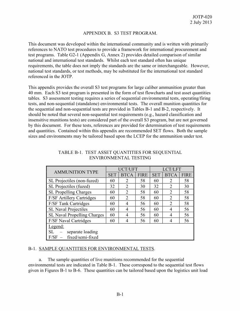
JOTP-020 2 July 2013
B-1
APPENDIX B. S3 TEST PROGRAM. This document was developed within the international community and is written with primarily references to NATO test procedures to provide a framework for international procurement and test programs. Table G2-1 (Appendix G, Annex 2) provides detailed comparison of similar national and international test standards. Whilst each test standard often has unique requirements, the table does not imply the standards are the same or interchangeable. However, national test standards, or test methods, may be substituted for the international test standard referenced in the JOTP. This appendix provides the overall S3 test programs for large caliber ammunition greater than 40 mm. Each S3 test program is presented in the form of test flowcharts and test asset quantities tables. S3 assessment testing requires a series of sequential environmental tests, operating/firing tests, and non-sequential (standalone) environmental tests. The overall munition quantities for the sequential and non-sequential tests are provided in Tables B-1 and B-2, respectively. It should be noted that several non-sequential test requirements (e.g., hazard classification and insensitive munitions tests) are considered part of the overall S3 program, but are not governed by this document. For these tests, references are provided for determination of test requirements and quantities. Contained within this appendix are recommended SET flows. Both the sample sizes and environments may be tailored based upon the LCEP for the ammunition under test.
TABLE B-1. TEST ASSET QUANTITIES FOR SEQUENTIAL ENVIRONMENTAL TESTING
AMMUNITION TYPE UCT/UFT LCT/LFT
SET BTCA FIRE SET BTCA FIRE SL Projectiles (non-fuzed) 60 2 58 60 2 58 SL Projectiles (fuzed) 32 2 30 32 2 30 SL Propelling Charges 60 2 58 60 2 58 F/SF Artillery Cartridges 60 2 58 60 2 58 F/SF Tank Cartridges 60 4 56 60 2 58 SL Naval Projectiles 60 4 56 60 4 56 SL Naval Propelling Charges 60 4 56 60 4 56 F/SF Naval Cartridges 60 4 56 60 4 56 Legend: SL – separate loading F/SF – fixed/semi-fixed
B-1. SAMPLE QUANTITIES FOR ENVIRONMENTAL TESTS. a. The sample quantities of live munitions recommended for the sequential environmental tests are indicated in Table B-1. These correspond to the sequential test flows given in Figures B-1 to B-6. These quantities can be tailored based upon the logistics unit load
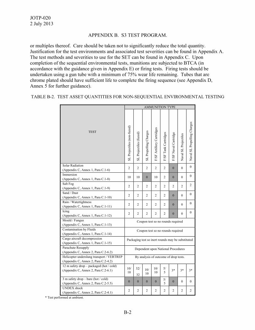
JOTP-020 2 July 2013
B-2
APPENDIX B. S3 TEST PROGRAM.
or multiples thereof. Care should be taken not to significantly reduce the total quantity. Justification for the test environments and associated test severities can be found in Appendix A. The test methods and severities to use for the SET can be found in Appendix C. Upon completion of the sequential environmental tests, munitions are subjected to BTCA (in accordance with the guidance given in Appendix E) or firing tests. Firing tests should be undertaken using a gun tube with a minimum of 75% wear life remaining. Tubes that are chrome plated should have sufficient life to complete the firing sequence (see Appendix D, Annex 5 for further guidance). TABLE B-2. TEST ASSET QUANTITIES FOR NON-SEQUENTIAL ENVIRONMENTAL TESTING
TEST
AMMUNITION TYPE
SL
Pro
ject
iles
(no
n-fu
zed)
SL
Pro
ject
iles
(fu
zed)
SL
Pro
pell
ing
Cha
rges
F/S
F A
rtil
lery
Car
trid
ges
F/S
F T
ank
Car
trid
ges
F/S
F N
aval
Car
trid
ge
Nav
al S
L P
roje
ctil
es
Nav
al S
L P
rope
llin
g C
harg
es
Solar Radiation (Appendix C, Annex 1, Para C.1-6)
2 2 2 2 2 0 0 0
Immersion (Appendix C, Annex 1, Para C.1-8)
10 10 0 10 2 0 0 0
Salt Fog (Appendix C, Annex 1, Para C.1-9)
2 2 2 2 2 2 2 2
Sand / Dust (Appendix C, Annex 1, Para C.1-10)
2 2 2 2 2 0 0 0
Rain / Watertightness (Appendix C, Annex 1, Para C.1-11)
2 2 2 2 2 0 0 0
Icing (Appendix C, Annex 1, Para C.1-12)
2 2 2 2 2 0 0 0
Mould / Fungus (Appendix C, Annex 1, Para C.1-13)
Coupon test so no rounds required
Contamination by Fluids (Appendix C, Annex 1, Para C.1-14)
Coupon test so no rounds required
Cargo aircraft decompression (Appendix C, Annex 1, Para C.1-15)
Packaging test so inert rounds may be substituted
Parachute Resupply (Appendix C, Annex 2, Para C.2-6.2)
Dependent upon National Procedures
Helicopter underslung transport / VERTREP (Appendix C, Annex 2, Para C.2-4.2)
By analysis of outcome of drop tests.
12 m safety drop – packaged (hot / cold) (Appendix C, Annex 2, Para C.2-6.1)
10/ 10
32/
32
10/ 10
10/ 10
5/ 5
3* 3* 3*
3 m safety drop – bare (hot / cold) (Appendix C, Annex 2, Para C.2-5.5)
0 0 0 0 5/ 5
0 0 0
UNDEX shock (Appendix C, Annex 2, Para C.2-4.1)
2 2 2 2 2 2 2 2
* Test performed at ambient.
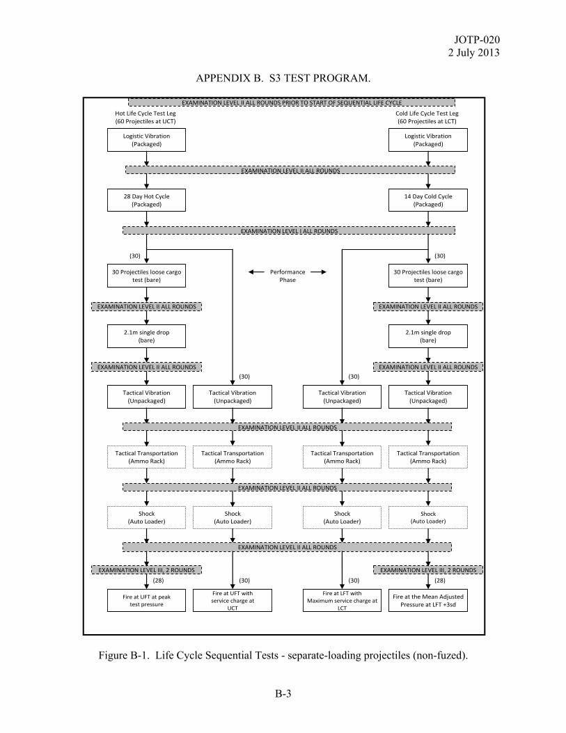
JOTP-020 2 July 2013
B-3
APPENDIX B. S3 TEST PROGRAM.
Figure B-1. Life Cycle Sequential Tests - separate-loading projectiles (non-fuzed).
EXAMINATION LEVEL II ALL ROUNDS PRIOR TO START OF SEQUENTIAL LIFE CYCLE
2.1m single drop (bare)
Logistic Vibration (Packaged)
Logistic Vibration (Packaged)
Fire at UFT at peak test pressure
Fire at UFT with service charge at
UCT
Fire at LFT with Maximum service charge at
LCT
Fire at the Mean Adjusted Pressure at LFT +3sd
Shock (Auto Loader)
Shock (Auto Loader)
Shock (Auto Loader)
Shock (Auto Loader)
Tactical Transportation (Ammo Rack)
Tactical Transportation (Ammo Rack)
Tactical Transportation (Ammo Rack)
Tactical Transportation (Ammo Rack)
Tactical Vibration (Unpackaged)
Tactical Vibration (Unpackaged)
Tactical Vibration (Unpackaged)
Tactical Vibration (Unpackaged)
2.1m single drop (bare)
30 Projectiles loose cargo test (bare)
30 Projectiles loose cargo test (bare)
28 Day Hot Cycle (Packaged)
14 Day Cold Cycle (Packaged)
EXAMINATION LEVEL II ALL ROUNDS
EXAMINATION LEVEL I ALL ROUNDS
Hot Life Cycle Test Leg (60 Projectiles at UCT)
Cold Life Cycle Test Leg (60 Projectiles at LCT)
Performance Phase
(30) (30)
(30) (30)
(30) (30) (28) (28)
EXAMINATION LEVEL II ALL ROUNDS
EXAMINATION LEVEL II ALL ROUNDS
EXAMINATION LEVEL II ALL ROUNDS
EXAMINATION LEVEL II ALL ROUNDS
EXAMINATION LEVEL II ALL ROUNDS
EXAMINATION LEVEL II ALL ROUNDS
EXAMINATION LEVEL II ALL ROUNDS
EXAMINATION LEVEL III, 2 ROUNDS EXAMINATION LEVEL III, 2 ROUNDS
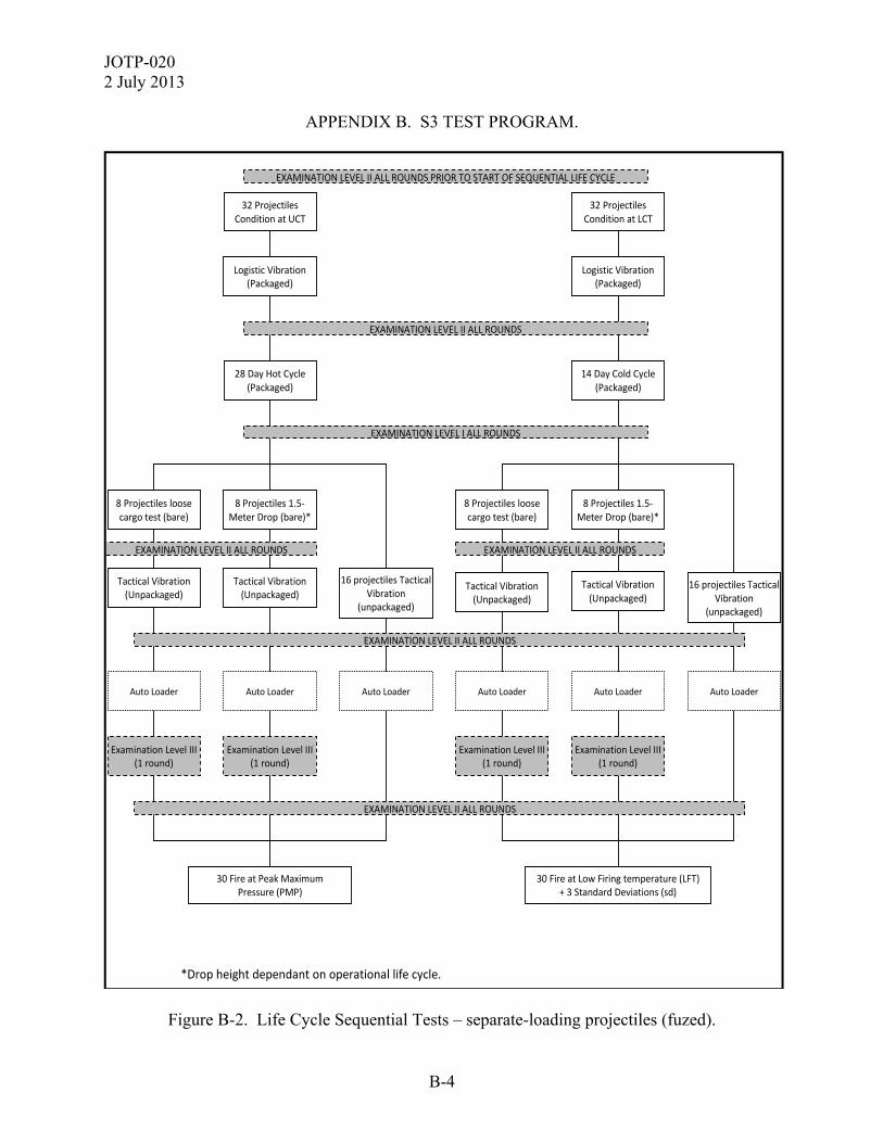
JOTP-020 2 July 2013
B-4
APPENDIX B. S3 TEST PROGRAM.
Figure B-2. Life Cycle Sequential Tests – separate-loading projectiles (fuzed).
*Drop height dependant on operational life cycle.
EXAMINATION LEVEL II ALL ROUNDS PRIOR TO START OF SEQUENTIAL LIFE CYCLE
32 Projectiles Condition at LCT
Logistic Vibration (Packaged)
Auto Loader
30 Fire at Low Firing temperature (LFT) + 3 Standard Deviations (sd)
Examination Level III(1 round)
Tactical Vibration (Unpackaged)
Tactical Vibration (Unpackaged)
8 Projectiles loose cargo test (bare)
16 projectiles Tactical Vibration
(unpackaged)
14 Day Cold Cycle (Packaged)
8 Projectiles 1.5‐Meter Drop (bare)*
Auto Loader Auto Loader
Examination Level III (1 round)
32 Projectiles Condition at UCT
Logistic Vibration (Packaged)
Auto Loader
30 Fire at Peak Maximum Pressure (PMP)
Examination Level III (1 round)
Tactical Vibration (Unpackaged)
Tactical Vibration (Unpackaged)
8 Projectiles loose cargo test (bare)
16 projectiles Tactical Vibration
(unpackaged)
28 Day Hot Cycle (Packaged)
8 Projectiles 1.5‐Meter Drop (bare)*
Auto Loader Auto Loader
Examination Level III (1 round)
EXAMINATION LEVEL II ALL ROUNDS
EXAMINATION LEVEL I ALL ROUNDS
EXAMINATION LEVEL II ALL ROUNDS
EXAMINATION LEVEL II ALL ROUNDS EXAMINATION LEVEL II ALL ROUNDS
EXAMINATION LEVEL II ALL ROUNDS
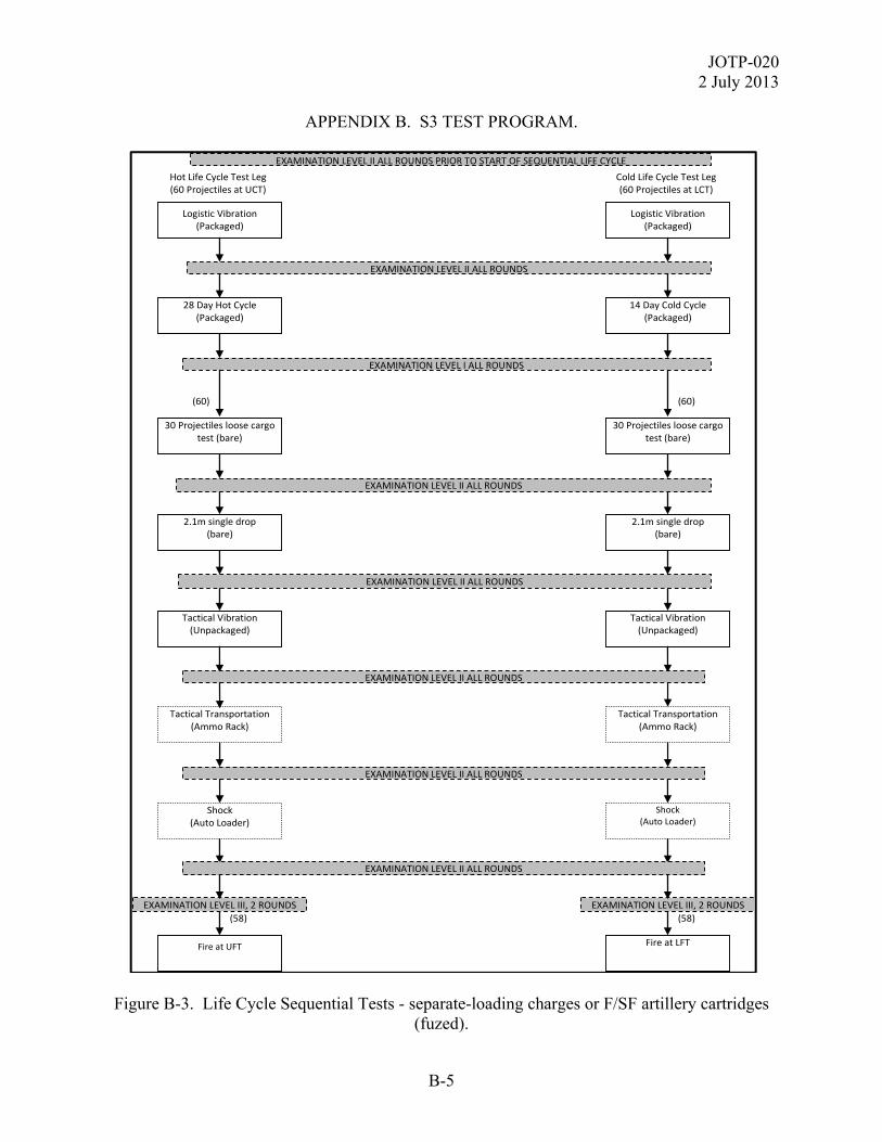
JOTP-020 2 July 2013
B-5
APPENDIX B. S3 TEST PROGRAM.
Figure B-3. Life Cycle Sequential Tests - separate-loading charges or F/SF artillery cartridges (fuzed).
EXAMINATION LEVEL II ALL ROUNDS PRIOR TO START OF SEQUENTIAL LIFE CYCLE
2.1m single drop (bare)
Logistic Vibration (Packaged)
Logistic Vibration (Packaged)
Fire at UFT Fire at LFT
Shock (Auto Loader)
Shock (Auto Loader)
Tactical Transportation (Ammo Rack)
Tactical Transportation(Ammo Rack)
Tactical Vibration (Unpackaged)
Tactical Vibration (Unpackaged)
2.1m single drop (bare)
30 Projectiles loose cargo test (bare)
30 Projectiles loose cargo test (bare)
28 Day Hot Cycle (Packaged)
14 Day Cold Cycle (Packaged)
EXAMINATION LEVEL II ALL ROUNDS
EXAMINATION LEVEL I ALL ROUNDS
Hot Life Cycle Test Leg (60 Projectiles at UCT)
Cold Life Cycle Test Leg(60 Projectiles at LCT)
(60) (60)
(58) (58)
EXAMINATION LEVEL II ALL ROUNDS
EXAMINATION LEVEL II ALL ROUNDS
EXAMINATION LEVEL II ALL ROUNDS
EXAMINATION LEVEL II ALL ROUNDS
EXAMINATION LEVEL II ALL ROUNDS
EXAMINATION LEVEL III, 2 ROUNDS EXAMINATION LEVEL III, 2 ROUNDS
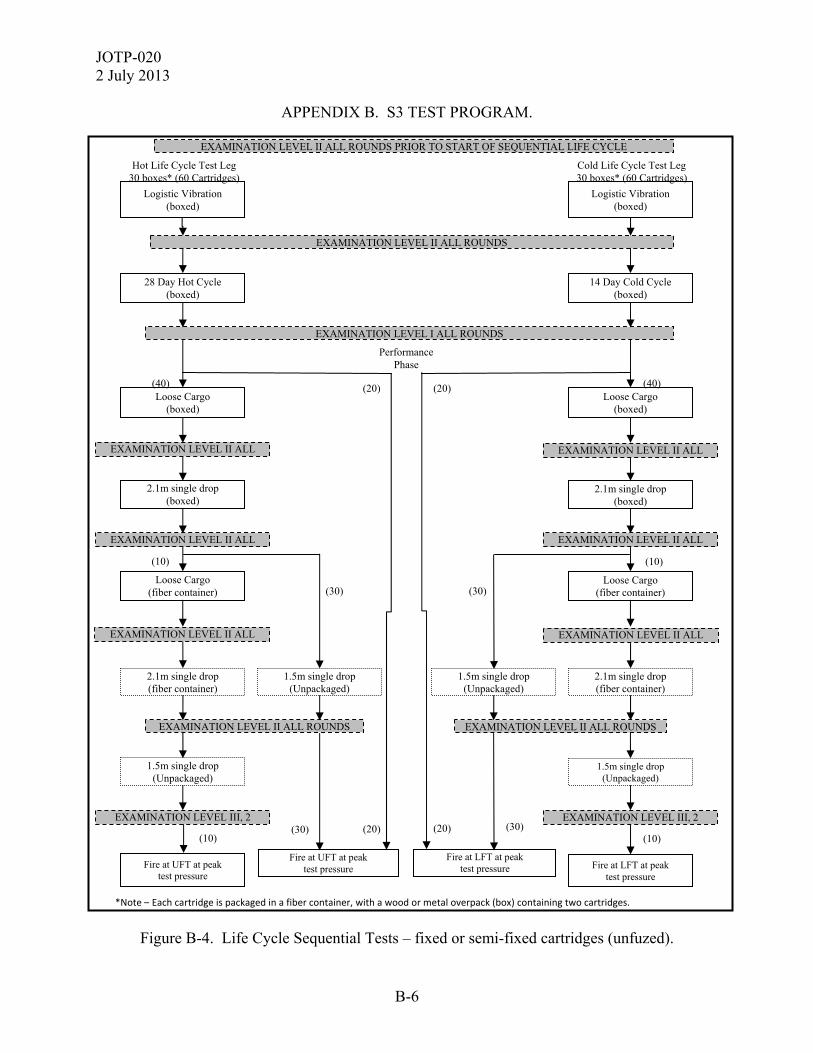
JOTP-020 2 July 2013
B-6
APPENDIX B. S3 TEST PROGRAM.
Figure B-4. Life Cycle Sequential Tests – fixed or semi-fixed cartridges (unfuzed).
Fire at UFT at peak test pressure
Fire at UFT at peak test pressure
Fire at LFT at peak test pressure Fire at LFT at peak
test pressure
1.5m single drop (Unpackaged)
1.5m single drop (Unpackaged)
2.1m single drop (fiber container)
1.5m single drop (Unpackaged)
1.5m single drop (Unpackaged)
2.1m single drop (fiber container)
(30) (30) (10) (10)
EXAMINATION LEVEL II ALL ROUNDS
EXAMINATION LEVEL III, 2 EXAMINATION LEVEL III, 2
2.1m single drop (boxed)
Loose Cargo (fiber container)
Loose Cargo (fiber container)
2.1m single drop (boxed)
Loose Cargo (boxed)
Loose Cargo (boxed)
Performance Phase
(40) (40) (20) (20)
28 Day Hot Cycle (boxed)
14 Day Cold Cycle (boxed)
EXAMINATION LEVEL I ALL ROUNDS
EXAMINATION LEVEL II ALL ROUNDS PRIOR TO START OF SEQUENTIAL LIFE CYCLE
Logistic Vibration (boxed)
Logistic Vibration (boxed)
EXAMINATION LEVEL II ALL ROUNDS
Hot Life Cycle Test Leg 30 boxes* (60 Cartridges)
Cold Life Cycle Test Leg 30 boxes* (60 Cartridges)
EXAMINATION LEVEL II ALL EXAMINATION LEVEL II ALL
EXAMINATION LEVEL II ALL EXAMINATION LEVEL II ALL
(10)
EXAMINATION LEVEL II ALL EXAMINATION LEVEL II ALL
(30) (30)
(10)
EXAMINATION LEVEL II ALL ROUNDS
(20) (20)
*Note – Each cartridge is packaged in a fiber container, with a wood or metal overpack (box) containing two cartridges.

JOTP-020 2 July 2013
B-7
APPENDIX B. S3 TEST PROGRAM.
Figure B-5. Life Cycle Sequential Tests - Tank Munitions.
Fire 5 from Cold
Tactical Transportation (Loose Cargo, Packaged)
(5)
(49)
Fire 5 from Cold
(39)
(5)
Tactical Drop (1.5-Meter Unpackaged Drops, two each)
(23) (11 Hot/Humid
12 Hot/Dry)
(44)
Tactical Transportation (Unpackaged)
EXAMINATION LEVEL II ALL ROUNDS
(44)
(26)
(44) (28)
(28)
(28)
EXAMINATION LEVEL II, ALL ROUNDS; EXAMINATION LEVEL III, 1 ROUND FROM EACH STORAGE CONDITION (HOT DRY, HOT HUMID, AND COLD)
Auto Loader
Tactical Transportation (Unpackaged)
Tactical Storage (Unpackaged) 14(15-day hot/dry) / 14 (15-day hot/humid)
EXAMINATION LEVEL II ALL ROUNDS
(23)
Tactical Drop (1.5-Meter Unpackaged Drops, two each)
(3 Hot Humid 2 Hot Dry)
EXAMINATION LEVEL II ALL ROUNDS
(5)
Fire 5 from Hot/Humid cycle
(5) Fire 5 from Hot/Dry Cycle
EXAMINATION LEVEL II ALL ROUNDS
Tactical Transportation (Loose Cargo, Packaged)
Fire 5 from Hot/Humid Cycle
EXAMINATION LEVEL II ALL ROUNDS Fire 5 from
Hot/Dry Cycle (38)
Tactical Drop (2.1-Meter Individual Packaged Drops, two each)
Tactical Drop (2.1-Meter Individual Packaged Drops, two each)
Fire 5 from Hot/Humid Cycle
Fire 5 from Hot/Dry Cycle (48)
Logistic Handling (2.1-Meter Pallet Drop)
(54)
Fire 5 from Cold
(59) Logistic Handling
(2.1-Meter Pallet Drop)
EXAMINATION LEVEL II ALL ROUNDS
(58)
Logistic Transportation (Pallet)
Logistic Storage (3-day cold)
EXAMINATION LEVEL I, ALL ROUNDS; EXAMINATION LEVEL III, 1 ROUND FROM EACH STORAGE
Cold Life Cycle Test Leg (60 service rds)
(60) Tactical Transportation
(Secured Cargo, Palletized)
(30) (30)
(60)
Logistic Transportation (Pallet)
Logistic Storage (7-day hot/dry)
EXAMINATION LEVEL II ALL ROUNDS PRIOR TO START OF SEQUENTIAL LIFE CYCLE
Hot Life Cycle Test Leg (60 service rds)
Logistic Storage (10-day hot/humid)
Tactical Transportation (Secured Cargo, Palletized)
Fire Remaining Rounds at UFT
(43)
Auto Loader
Tactical Storage (Unpackaged) 15-day cycle test
Fire Remaining Rounds at LFT
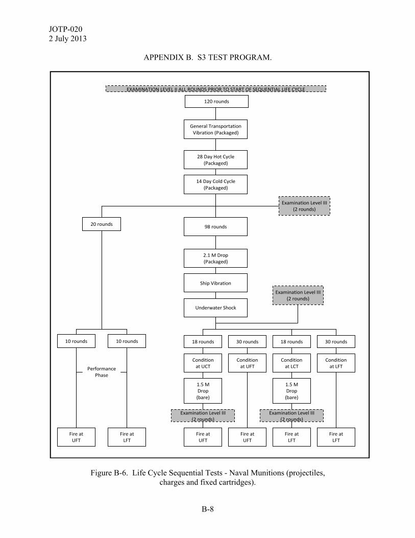
JOTP-020 2 July 2013
B-8
APPENDIX B. S3 TEST PROGRAM.
Figure B-6. Life Cycle Sequential Tests - Naval Munitions (projectiles, charges and fixed cartridges).
General Transportation Vibration (Packaged)
120 rounds
Examination Level III (2 rounds)
Examination Level III (2 rounds)
2.1 M Drop (Packaged)
Ship Vibration
Underwater Shock
28 Day Hot Cycle (Packaged)
14 Day Cold Cycle (Packaged)
98 rounds
18 rounds 18 rounds 30 rounds 30 rounds
Condition at UCT
Condition at UFT
Condition at LCT
Condition at LFT
1.5 M Drop (bare)
Fire at UFT
1.5 M Drop (bare)
Examination Level III (2 rounds)
Examination Level III (2 rounds)
Fire at LFT
Fire at UFT
Fire at LFT
20 rounds
10 rounds 10 rounds
Fire at UFT
Fire at LFT
Performance Phase
EXAMINATION LEVEL II ALL ROUNDS PRIOR TO START OF SEQUENTIAL LIFE CYCLE
JOTP-020 2 July 2013
B-9
APPENDIX B. S3 TEST PROGRAM. b. Consideration should be given to static firing of the payloads for carrier type projectiles. Any such firings should be undertaken with full instrumentation appropriate for monitoring the output of that payload. A minimum of five payloads should be functioned at each firing temperature. c. During the sequential environmental test, rounds may become unsafe. If this occurs, remove them from the sequence, set them aside and document the damage for subsequent assessment. Damaged rounds may be replaced but would not count as a full sequential round (i.e., not been subjected to the full sequence). Furthermore, some rounds might become damaged to such extent that they could not be fired but do not present a direct safety hazard. In such case, these rounds could complete the environmental sequence and may be used for BTCA in lieu of the scheduled BTCA rounds. B-2. SAMPLE QUANTITIES FOR NON-SEQUENTIAL ENVIRONMENTAL TESTS. The sample quantities of live munitions recommended for the non-sequential environmental tests are indicated in Table B-2. These tests are Life Cycle dependant and may not necessarily be required. Justification for the test environments and associated test severities can be found in Appendix A. The test methods and severities to use for the non-sequential environmental tests can be found in Appendix C. Upon completion of the non-sequential environmental tests, munitions are subjected to Level 1 inspection, and depending on the test may see Level 2 inspection, Level 3 inspection, or be fired. B-3. SAMPLE QUANTITIES FOR SAFE FUNCTIONING AND GUN INTERFACE ASSESSMENT TESTS. The sample quantities of live munitions recommended for the safe functioning assessment tests are indicated in Table B-3.

JOTP-020 2 July 2013
B-10
APPENDIX B. S3 TEST PROGRAM.
TABLE B-3. TEST ASSET QUANTITIES FOR SAFE FUNCTIONING AND GUN INTERFACE TESTS
TEST
AMMUNITION TYPE
Tem
pera
ture
SL
Pro
ject
iles
(non
-fuz
ed)
SL
Pro
ject
iles
(fu
zed)
SL
Pro
pelli
ng C
harg
es
F/S
F A
rtil
lery
Car
trid
ges
F/S
F T
ank
Car
trid
ges
F/S
F N
aval
Car
trid
ges
SL
Nav
al P
roje
ctile
s
SL
Nav
al P
rope
lling
Cha
rges
Projectile Strength of Design – Inert Fill Phase (Appendix D, Annex 1)
UFT LFT
10 10
10 10
0 0
10 10
10 10
10 10
10 10
0 0
Projectile Strength of Design – Live Fill Phase (1) (Appendix D, Annex 1)
UFT LFT
10 10
10 10
0 0
10 10
10 10
10 10
10 10
0 0
Projectile Safety in Gun (Appendix D, Annex 2)
UFT LFT
60 60
60 60
35 35
60 60
60 60
60 60
60 60
35 35
Preliminary Propelling System Safety (Appendix D, Annex 3)
UFT
+21°C LFT
0 0 0
0 0 0
20 20 20
20 20 20
20 20 20
20 20 20
0 0 0
20 20 20
Final Propelling System Safety (Appendix D, Annex 4)
UFT 0 0 56 56 56 56 0 56
Worn Tube Safety – Inert Fill Phase (1)
(Appendix D, Annex 5)
UFT LFT
5 5
5 5
0 0
5 5
10 10
5 5
5 5
0 0
Worn Tube Safety – Live Fill Phase(2) (Appendix D, Annex 5)
UFT LFT
20/5 20/5
20/5 20/5
0 0
20/5 20/5
10 10
20/5 20/5
20/5 20/5
0 0
Load/unload (Appendix D, Annex 6, para D.6-3)
As required
0 0 0 5 5 5 0 0
Fallback (ITOP 04-2-802)
As required
5 5 0 0 0 0 5 0
Shock attenuating plug (Appendix D, Annex 6, para D.6-2)
UFT LFT
20 20
0 0
0 0
0 0
0 0
0 0
0 0
0 0
Hot gun cook-off (Appendix D, Annex 6, para D.6-1)
Minimum of one, but additional munitions as required
7 7 7
Alternative zone firings As required Sticker assessment (Appendix D, Annex 6, para D.6-4)
As required
Charge adjust, warmer and interference rounds as required for individual tests Notes: (1) Initial test phase consists of firing inert filled projectiles. Second test phase consists of firing live filled projectiles. If the end user configuration does not contain energetic or other hazardous materials, then the second (live) test phase is not required. (2) Test quantities vary according to projectile type.
JOTP-020 2 July 2013
B-11
APPENDIX B. S3 TEST PROGRAM. a. Worn Tube. Artillery projectiles loaded with HE or other hazardous fillings. (1) Inert Phase. Fire a sample of 10 inert-loaded projectiles - 5 at LFT and 5 at UFT, with the aim of recovering at least 50% of the projectiles for inspection. (2) Live Phase. If there is no significant damage, then fire live projectiles as follows: (a) HE filled projectiles. 40 live HE filled projectiles with inert or dummy fuzes - 20 at LFT and 20 at UFT, with the aim of recovering 50% of the projectiles for inspection. (b) Payload dispensing projectiles (HE or other hazardous fillings). 10 projectiles comprising live payload, live expelling charges and inert or dummy fuzes - 5 at LFT and 5 at UFT, with the aim of recovering 50% of the projectiles for inspection. b. Tank projectiles explosive filled and KE. (1) Inert Phase for HE projectiles and also KE projectiles. Fire a sample of 20 inert projectiles - 10 at LFT and 10 at UFT, with the aim of recovering at least 50% of the projectiles fired. It’s recommended to fire the projectiles using two tubes. (2) Live Phase. If there is no significant damage, then fire live projectiles as follows: HE filled projectiles, 20 live HE filled projectiles - 10 at LFT and 10 at UFT. B-4. SAMPLE QUANTITIES FOR NON-SEQUENTIAL SAFETY TESTS AND ASSESSMENTS. The following tests (or test evidence) are also required. Alternatively, the objectives of these tests may be met based upon assessment of evidence from other tests carried out upon the munition. a. Hazard Classification Testing per STANAG 4123 and AASTP-3. Test quantities are given in the referenced test standard. b. Insensitive Munitions Tests per STANAG 4439 and AOP-39. Test quantities are given in the referenced test standard. c. Weapon Danger Area as described in Appendix D, Annex 7, paragraph D.7-3. This may be by assessment of evidence from other tests carried out upon the munition. (1) Warhead Arena as described in Appendix D, Annex 7, paragraph D.7-1 This will require a minimum of two projectiles. (2) Range Safety will require test quantities dependent upon national procedures for ricochet assessment.

JOTP-020 2 July 2013
B-12
APPENDIX B. S3 TEST PROGRAM. d. Health Hazard assessment, incorporating toxic substances, blast overpressure and acoustic energy as described in Appendix D, Annex 7, paragraph D.7-2. Separate tests to obtain the data for these assessments may not be required. Data may be acquired during the conduct of other firing tests using appropriate instrumentation. e. If the munitions contain electrically susceptible components (e.g., electrical primers, electrical initiation devices), then E3 characterization tests will be required (Appendix C, Annex 3). Instrumented components may be substituted where actual measurement of the maximum no-fire stimulus may be obtained. Systems or subsystems incorporating ESADs must be tested while in the functional mode. At a minimum, E3 assessment tests will include the following: (1) One (1) live munition and 1 inert munition with 20 live sets of EID/ESADs for Lightning Hazard. (2) One (1) inert munition (no fill/energetic material) capable of disassembly/reassembly without damage with instrumented EID/ESAD empty-inert with bridge intact and exposed for HERO Tests. (3) One (1) inert munition with 30 live sets of EID/ESADs for ESD Tests (20 for personnel and 10 for helicopter-borne ESD).

JOTP-020 2 July 2013
C-1
APPENDIX C. ENVIRONMENTAL TEST DESCRIPTIONS. This document was developed within the international community and is written with primarily references to NATO test procedures to provide a framework for international procurement and test programs. Table G2-1 (Appendix G, Annex 2) provides detailed comparison of similar national and international test standards. Whilst each test standard often has unique requirements, the table does not imply the standards are the same or interchangeable. However, national test standards, or test methods, may be substituted for the international test standard referenced in the JOTP. This appendix provides descriptions of all the environmental (climatic, dynamic, and electrical) tests that should be selected based upon your LCEP as described in the Safety Test Programs included in Appendix B. Background and rationale for these tests are provided in Appendix A.

JOTP-020 2 July 2013
C-2
APPENDIX C. ENVIRONMENTAL TEST DESCRIPTIONS. ANNEX 1. CLIMATIC TEST DESCRIPTIONS.
C.1-1. HUMID HEAT (HOT HUMID CYCLE). Perform Aggravated Humidity testing in accordance with AECTP 300, Method 306, Procedure I using the following test parameters: a. Munition Configuration: Unpackaged munitions. b. Test Level: AECTP 300, Method 306, Figure 1 ‘Aggravated Cycle (cycle 3)’. c. Test Duration: Ten 24-hour cycles to be applied. C.1-2. LOW TEMPERATURE STORAGE. Perform Low Temperature testing in accordance with AECTP 300, Method 303, Procedure I using the following test parameters: a. Munition Configuration: Storage configuration (packaged or unpackaged munitions). b. Test Level: Constant temperature of -51 °C. c. Test Duration: 72 hours (3 days) continuous. C.1-3. LOW TEMPERATURE CYCLE. This test may be performed in addition to, or as an alternative to, the Low Temperature Storage Test at the discretion of the National Safety Authority. Perform Low Temperature testing in accordance with AECTP 300, Method 303, Procedure I using the following test parameters: a. Munition Configuration: Storage configuration (packaged or unpackaged munitions). b. Test Level: AECTP 230, Leaflet 2311/2, Table 14 ‘C2 Cycles’ (Temperatures: -37 °C to -46 °C.). c. Test Duration: 14 diurnal (24-hour) cycles to be applied. C.1-4. HIGH TEMPERATURE STORAGE. Perform High Temperature testing in accordance with AECTP 300, Method 302, Procedure I using the following test parameters: a. Munition Configuration: Storage configuration (packaged or unpackaged munitions). b. Test Levels:
JOTP-020 2 July 2013
C-3
APPENDIX C. ENVIRONMENTAL TEST DESCRIPTIONS. ANNEX 1. CLIMATIC TEST DESCRIPTIONS.
(1) Inert projectiles or munitions that do not contain energetic materials that are temperature sensitive: Constant temperature of 71 °C for 216 hours (9 days). (2) Munitions that contain energetic materials that are temperature sensitive (e.g., explosives based on TNT, or double/triple base propellants): Constant temperature of 58 °C for 528 hours (22 days). C.1-5. HIGH TEMPERATURE CYCLE. Perform High Temperature testing in accordance with AECTP 300, Method 302, Procedure I using the following test parameters: a. Munition Configuration: Storage configuration (packaged or unpackaged munitions). b. Test Level: AECTP 300, Method 302, Table 1 ‘High Temperature Diurnal Cycles’ Category A1 Induced Conditions (Temperatures: 33 °C to 71 °C.). c. Test Duration: 28 diurnal (24-hour) cycles to be applied. C.1-6. SOLAR RADIATION. Perform Solar Radiation testing in accordance with AECTP 300, Method 305, Procedure I using the following test parameters: a. Munition Configuration: Unpackaged munitions. b. Test Level: AECTP 300, Method 305, Figure 1 ‘Cycling Test’ Category A1 (temperatures: 32 °C to 49 °C. Irradiance: 0 W/m2 to 1120 W/m2.). There is no requirement to test for Naval gun ammunition. c. Test Duration: Seven 24-hour solar cycles to be applied. C.1-7. THERMAL SHOCK. Perform Thermal Shock testing in accordance with AECTP 300, Method 304, Procedure I using the following test parameters: a. Munition Configuration: Unpackaged munitions. b. Test Levels: (1) Low Temperature Shock: 21 °C to -51 °C.
JOTP-020 2 July 2013
C-4
APPENDIX C. ENVIRONMENTAL TEST DESCRIPTIONS. ANNEX 1. CLIMATIC TEST DESCRIPTIONS.
(2) High Temperature Shock: Unpackaged SRE temperature to -5 °C. c. Test Duration: Five cycles of both the low and high temperature shock tests (10 shocks in total). The munitions are to remain in each test chamber until temperature stabilization is achieved (24 hours maximum for unpackaged munitions). C.1-8. IMMERSION. Perform Immersion testing in accordance with AECTP 300, Method 307, Procedure I using the following test parameters: a. Munition Configuration: Unpackaged munitions. b. Conditioning Temperature: Munitions are to be preconditioned to a temperature of 27 °C above the water temperature to represent exposure to solar heating immediately prior to immersion {per AECTP 300, Method 307, Paragraph 2.4.1a(1)}. There is no requirement to test for Naval gun ammunition. c. Depth of Immersion: Complete immersion to a depth of 1 meter, or equivalent pressure. d. Test Duration: 30 minutes immersion. e. Other: Weigh the test munition(s) prior to testing, immediately after testing once surface moisture has been removed, and after drying at laboratory ambient temperature for 24 hours. Alternatively, the munition(s) may be disassembled to determine presence of moisture and ingress path(s). C.1-9. SALT FOG. Perform Salt Fog testing in accordance with AECTP 300, Method 309 using the following test parameters: a. Munition Configuration: Unpackaged munitions. b. Test Levels: Use default parameters as specified in AECTP 300, Method 309. c. Test Duration: Two alternating wet-dry cycles. C.1-10. SAND AND DUST. Perform Sand and Dust testing in accordance with AECTP 300, Method 313, Procedures I (Blowing Dust) and II (Blowing Sand) using the following test parameters:
JOTP-020 2 July 2013
C-5
APPENDIX C. ENVIRONMENTAL TEST DESCRIPTIONS. ANNEX 1. CLIMATIC TEST DESCRIPTIONS.
a. Munition Configuration: Unpackaged munitions. b. Conditioning Temperature: Munitions are to be preconditioned to a temperature of 49 °C prior to exposure. c. Test Levels: (1) Wind Blown Dust - Use default parameters as specified in AECTP 300, Method 313, Procedure II. (2) Wind Blown Sand - Use default parameters as specified in AECTP 300, Method 313, Procedure I for material that may be used near operating surface vehicles (sand concentration = 1.1±0.3 g/m3; wind velocity = 18 to 30 m/s). (3) There is no requirement to test for Naval gun ammunition. d. Test Duration: Apply default parameters as specified in AECTP 300, Method 313. Note that it is recommended to conduct the sand and dust tests individually. C.1-11. RAIN/WATERTIGHTNESS. Perform Rain/Watertightness testing in accordance with AECTP 300, Method 310, Procedure I using the following test parameters: a. Munition Configuration: Unpackaged munitions. b. Conditioning Temperature: Munitions are to be preconditioned to a temperature of 10 °C above the water temperature. c. Test Levels: Rainfall rate = 100 mm/hour. Wind velocity = 18 m/s. d. Test Duration: Two (2) hours. C.1-12. ICING. Perform Icing testing in accordance with AECTP 300, Method 311 using the following test parameters: a. Munition Configuration: Unpackaged munitions. b. Test Levels: Use default parameters as specified in AECTP 300, Method 311. c. Ice Thickness: 13 mm per AECTP 300, Method 311, Paragraph 2.4.6(b).
JOTP-020 2 July 2013
C-6
APPENDIX C. ENVIRONMENTAL TEST DESCRIPTIONS. ANNEX 1. CLIMATIC TEST DESCRIPTIONS.
d. Ice Removal: In accordance with approved field methodologies. C.1-13. MOLD/FUNGUS GROWTH. Perform Mold Growth testing in accordance with AECTP 300, Method 308, using the following test parameters: a. Munition Configuration: Unpackaged munitions. b. Test Duration: 28 days. c. This test should be conducted as a non-sequential test. C.1-14. CONTAMINATION BY FLUIDS. Perform Fluid Contamination testing in accordance with AECTP 300, Method 314, using the following test parameters: a. Munition Configuration: Unpackaged munitions. b. Test Requirements: To be tailored according to the LCEP. c. This test should be conducted as a non-sequential test. C.1-15. CARGO AIRCRAFT DECOMPRESSION. Perform Rapid Decompression testing in accordance with AECTP 300, Method 312, Procedure III using the following test parameters: a. Munition Configuration: Packaged munitions. b. Conditioning Temperature: Munitions are to be preconditioned to laboratory ambient temperature. c. Pressures: Initial pressure = 60 kPa. Final pressure = 18.8 kPa. d. Decompression Time: No longer than 15 seconds.

JOTP-020 2 July 2013
C-7
APPENDIX C. ENVIRONMENTAL TEST DESCRIPTIONS.
ANNEX 2. DYNAMIC TEST DESCRIPTIONS. C.2-1. LOGISTIC LAND TRANSPORTATION DYNAMICS – COMMERCIAL. C.2-1.1 Land Transportation Commercial (Common Carrier) Vibration. Perform vibration testing in accordance with AECTP 400, Method 401, Procedure III using the following test parameters: a. Munition Configuration: Packaged or palletized. b. Test Level: AECTP 400, Method 401, Figure A-1 ‘Ground Wheeled Common Carrier’. c. Test Duration: Equivalent to the distance specified in AECTP 100, Annex E, Appendix 1 for transportation by ‘Land Commercial Vehicle’ for either Artillery, Tank, Self-propelled gun or Naval gun ammunition. d. Test Temperature: Temperature condition the test munitions prior to, and during vibration testing. Stabilize all cold munitions to -46 °C, and all hot munitions to the packaged SRE temperature. Note: Although the Common Carrier vibration environment is relatively benign compared to other wheeled vehicle vibration environments, the test should not be tailored out due to the intent of loosening up the test munitions and packaging prior to conduct of temperature and humidity tests. C.2-1.2 Packaged Transit Drop – Palletized. Perform drop testing in accordance with AECTP 400, Method 414, Procedure I using the following test parameters: a. Munition Configuration: Palletized b. Test Level: Single drop of 2.1 m onto a concrete supported steel surface. c. Drop Orientation: Each pallet load is to be dropped once to impact base down. d. Test Temperature: Temperature condition the test munitions prior to testing. Stabilize all cold munitions to -46 °C, and all hot munitions to the packaged SRE temperature. The drop tests should be conducted within the shortest duration possible upon removal from the conditioned environment. The maximum duration should be no longer than 30 minutes. During transport from the conditioned environment to the test site, it is good practice to minimize heat
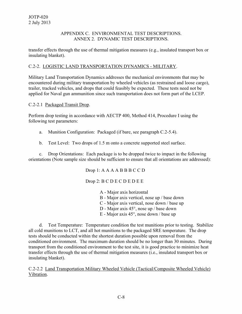
JOTP-020 2 July 2013
C-8
APPENDIX C. ENVIRONMENTAL TEST DESCRIPTIONS. ANNEX 2. DYNAMIC TEST DESCRIPTIONS.
transfer effects through the use of thermal mitigation measures (e.g., insulated transport box or insulating blanket). C.2-2. LOGISTIC LAND TRANSPORTATION DYNAMICS - MILITARY. Military Land Transportation Dynamics addresses the mechanical environments that may be encountered during military transportation by wheeled vehicles (as restrained and loose cargo), trailer, tracked vehicles, and drops that could feasibly be expected. These tests need not be applied for Naval gun ammunition since such transportation does not form part of the LCEP. C.2-2.1 Packaged Transit Drop. Perform drop testing in accordance with AECTP 400, Method 414, Procedure I using the following test parameters: a. Munition Configuration: Packaged (if bare, see paragraph C.2-5.4). b. Test Level: Two drops of 1.5 m onto a concrete supported steel surface. c. Drop Orientations: Each package is to be dropped twice to impact in the following orientations (Note sample size should be sufficient to ensure that all orientations are addressed): Drop 1: A A A A B B B C C D Drop 2: B C D E C D E D E E A - Major axis horizontal B - Major axis vertical, nose up / base down C - Major axis vertical, nose down / base up D - Major axis 45°, nose up / base down E - Major axis 45°, nose down / base up d. Test Temperature: Temperature condition the test munitions prior to testing. Stabilize all cold munitions to LCT, and all hot munitions to the packaged SRE temperature. The drop tests should be conducted within the shortest duration possible upon removal from the conditioned environment. The maximum duration should be no longer than 30 minutes. During transport from the conditioned environment to the test site, it is good practice to minimize heat transfer effects through the use of thermal mitigation measures (i.e., insulated transport box or insulating blanket). C.2-2.2 Land Transportation Military Wheeled Vehicle (Tactical/Composite Wheeled Vehicle) Vibration.

JOTP-020 2 July 2013
C-9
APPENDIX C. ENVIRONMENTAL TEST DESCRIPTIONS. ANNEX 2. DYNAMIC TEST DESCRIPTIONS.
Perform vibration testing in accordance with AECTP 400, Method 401, Procedure III using the following test parameters: a. Munition Configuration: Packaged. b. Test Level: AECTP 400, Method 401, Figure A-2 ‘Tactical Wheeled Vehicle - All Terrain’. c. Test Duration: Equivalent to 70% of the distance specified in AECTP 100, Annex E, Appendix 1 for transportation by ‘Land Military Vehicle’ for either artillery, tank or self-propelled gun. There is no requirement to test for Naval gun ammunition. d. Test Temperature: Temperature condition the test munitions prior to, and during vibration testing. Stabilize all cold munitions to LCT, and all hot munitions to the packaged SRE temperature. Note: Military wheeled vehicle transportation comprises two aspects to fully define the environment – vibration and shock. Therefore, at least one of the shock tests in paragraph C.2-2.5 is also required. C.2-2.3 Land Transportation Military Wheeled Trailer Vibration. Perform vibration testing in accordance with AECTP 400, Method 401, Procedure III using the following test parameters: a. Munition Configuration: Packaged. b. Test Level: AECTP 400, Method 401, Figure A-3 ‘Two Wheel Trailer’. c. Test Duration: Equivalent to 10% of the distance specified in AECTP 100, Annex E, Appendix 1 for transportation by ‘Land Military Vehicle’ for either artillery, tank or self-propelled gun. There is no requirement to test for Naval gun ammunition. d. Test Temperature: Temperature condition the test munitions prior to, and during vibration testing. Stabilize all cold munitions to -46 °C, and all hot munitions to the packaged SRE temperature. C.2-2.4 Land Transportation Military Tracked Vehicle Vibration. Perform vibration testing in accordance with AECTP 400, Method 401, Procedure III using the following test parameters: a. Munition Configuration: Packaged.

JOTP-020 2 July 2013
C-10
APPENDIX C. ENVIRONMENTAL TEST DESCRIPTIONS. ANNEX 2. DYNAMIC TEST DESCRIPTIONS.
b. Test Level: AECTP 400, Method 401, Figure B-1 ‘Materiel Transported as Secured Cargo’. c. Test Duration: Equivalent to 20% of the distance specified in AECTP 100, Annex E, Appendix 1 for transportation by ‘Land Military Vehicle’ for either artillery, tank or self-propelled gun. There is no requirement to test for Naval gun ammunition. d. Test Temperature: Temperature condition the test munitions prior to, and during vibration testing. Stabilize all cold munitions to -46 °C, and all hot munitions to the packaged SRE temperature. C.2-2.5 Military Vehicle Shock. When testing for wheeled vehicle, there is effectively a vibration and a shock element. In addition to the vibration tests above, at least one of the following transport shock test methods is required as determined by the LCEP. C.2-2.5.1 Restrained Cargo Shock. Perform shock testing in accordance with AECTP 400, Method 403 using the following test parameters: a. Munition Configuration: Packaged. b. Test Level: All shocks stated in Table C2-1, applied in each sense of each orthogonal axis. The shocks may be applied as either half-sine pulses or a single decaying sinusoidal pulse encompassing both senses in each axis. Terminal peak saw-tooth pulses or Shock Response Spectrum (SRS) methods may be substituted for the levels specified in Table C2-1 if it can be shown to produce equivalent velocities. AECTP 400, Method 417 provides guidance for SRS methods.
TABLE C2-1. RESTRAINED CARGO TRANSPORT SHOCK LEVELS
HALF SINE PULSE OR DECAYING SINUSOID Duration 5 ms Frequency (F): 100 Hz
Duration (T): 0.37 s (Number of Complete Cycles (N): 37)
Damping Factor: 3% of critical Amplitude
(g pk) Number of
Shocks Amplitude of First
Peak (g pk)
Number of Repetitions
8.0 42 8.0 42 10.0 21 10.0 21 12.0 3 12.0 3
Note: all shocks to be applied in each sense of each orthogonal axis.

JOTP-020 2 July 2013
C-11
APPENDIX C. ENVIRONMENTAL TEST DESCRIPTIONS. ANNEX 2. DYNAMIC TEST DESCRIPTIONS.
c. Test Duration: The numbers of shock repetitions stated in Table C2-1 are equivalent to 1000 km of off-road wheeled vehicle transportation. The number of shock repetitions to be applied should be calculated based on 70% of the distance specified in AECTP 100, Annex E, Appendix 1 for transportation by ‘Land Military Vehicle’ for either artillery, tank or self-propelled gun. However, the number of shock repetitions should be no fewer than those stated in Table C2-1. There is no requirement to test for Naval gun ammunition. d. Test Temperature: Temperature condition the test munitions prior to, and during shock testing. Stabilize all cold munitions to -46 °C, and all hot munitions to the packaged SRE temperature. C.2-2.5.2 Loose Cargo. Perform loose cargo (bounce) testing in accordance with AECTP 400, Method 406, Procedure I or II depending upon packaging, using the following test parameters: a. Munition Configuration: Bare or primary packaging (depending on the transport configuration). b. Test Level: Default values stated in AECTP 400, Method 406, Annex A: 300 rpm circular synchronous motion for 20 minutes. Where possible test in two orientations (horizontal and vertical), dividing total test duration between each. There is no requirement to test for Naval gun ammunition. c. Test Temperature: Temperature condition the test munitions prior to, and during testing. Stabilize all cold munitions to LCT, and all hot munitions to the packaged SRE temperature. C.2-3. LOGISTIC AIR TRANSPORTATION DYNAMICS - MILITARY. Military Air Transportation Dynamics addresses the mechanical environments that may be encountered during military transportation by fixed wing aircraft (propeller and jet), helicopter, and the shocks associated with parachute resupply. NOTE: All tests under these sections must be completed in order to satisfy the S3 objectives for Military Air Transportation. C.2-3.1 Fixed Wing Aircraft Transportation. Fixed Wing Aircraft Transportation includes both Turboprop and Jet Aircraft Vibration as described in the following paragraphs.
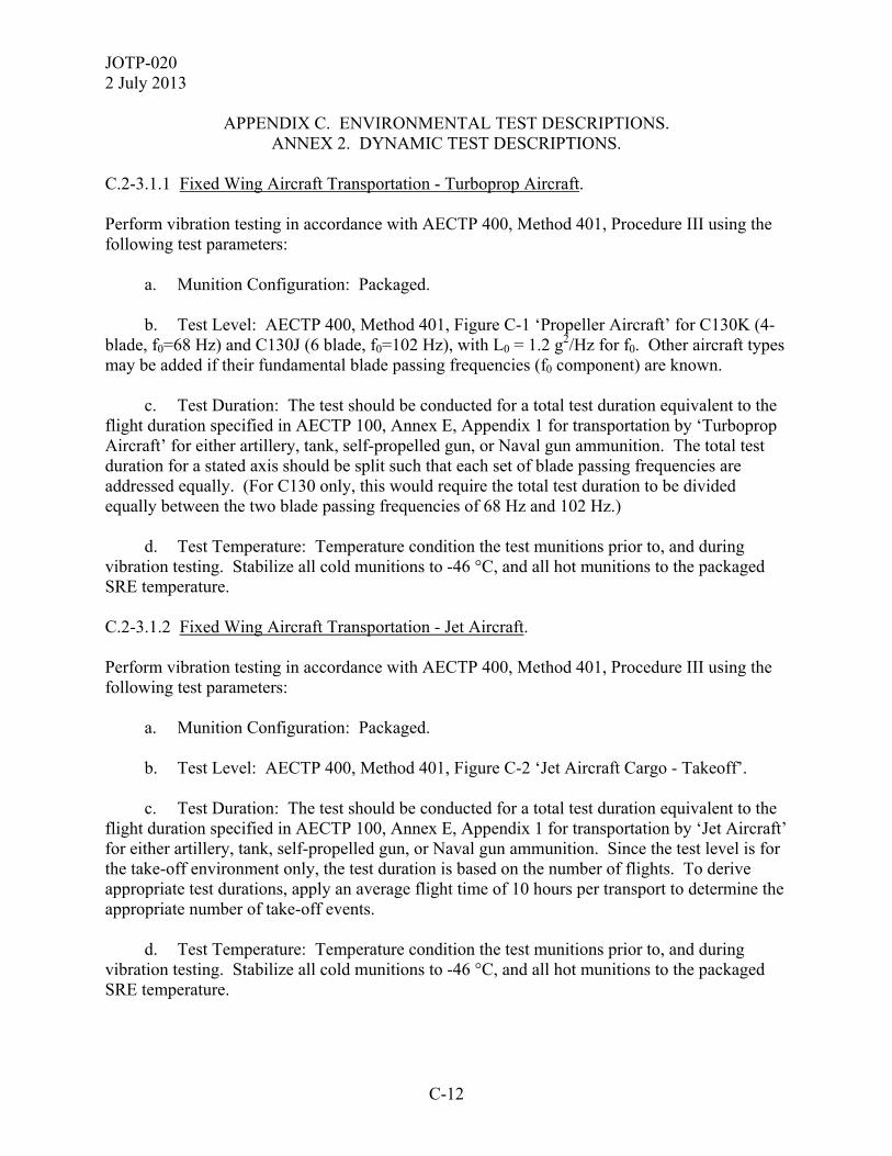
JOTP-020 2 July 2013
C-12
APPENDIX C. ENVIRONMENTAL TEST DESCRIPTIONS. ANNEX 2. DYNAMIC TEST DESCRIPTIONS.
C.2-3.1.1 Fixed Wing Aircraft Transportation - Turboprop Aircraft. Perform vibration testing in accordance with AECTP 400, Method 401, Procedure III using the following test parameters: a. Munition Configuration: Packaged. b. Test Level: AECTP 400, Method 401, Figure C-1 ‘Propeller Aircraft’ for C130K (4-blade, f0=68 Hz) and C130J (6 blade, f0=102 Hz), with L0 = 1.2 g2/Hz for f0. Other aircraft types may be added if their fundamental blade passing frequencies (f0 component) are known. c. Test Duration: The test should be conducted for a total test duration equivalent to the flight duration specified in AECTP 100, Annex E, Appendix 1 for transportation by ‘Turboprop Aircraft’ for either artillery, tank, self-propelled gun, or Naval gun ammunition. The total test duration for a stated axis should be split such that each set of blade passing frequencies are addressed equally. (For C130 only, this would require the total test duration to be divided equally between the two blade passing frequencies of 68 Hz and 102 Hz.) d. Test Temperature: Temperature condition the test munitions prior to, and during vibration testing. Stabilize all cold munitions to -46 °C, and all hot munitions to the packaged SRE temperature. C.2-3.1.2 Fixed Wing Aircraft Transportation - Jet Aircraft. Perform vibration testing in accordance with AECTP 400, Method 401, Procedure III using the following test parameters: a. Munition Configuration: Packaged. b. Test Level: AECTP 400, Method 401, Figure C-2 ‘Jet Aircraft Cargo - Takeoff’. c. Test Duration: The test should be conducted for a total test duration equivalent to the flight duration specified in AECTP 100, Annex E, Appendix 1 for transportation by ‘Jet Aircraft’ for either artillery, tank, self-propelled gun, or Naval gun ammunition. Since the test level is for the take-off environment only, the test duration is based on the number of flights. To derive appropriate test durations, apply an average flight time of 10 hours per transport to determine the appropriate number of take-off events. d. Test Temperature: Temperature condition the test munitions prior to, and during vibration testing. Stabilize all cold munitions to -46 °C, and all hot munitions to the packaged SRE temperature.
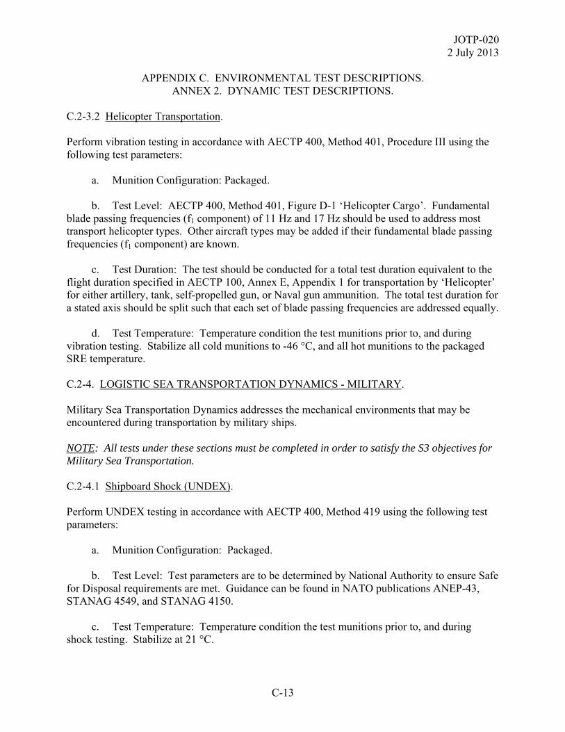
JOTP-020 2 July 2013
C-13
APPENDIX C. ENVIRONMENTAL TEST DESCRIPTIONS. ANNEX 2. DYNAMIC TEST DESCRIPTIONS.
C.2-3.2 Helicopter Transportation. Perform vibration testing in accordance with AECTP 400, Method 401, Procedure III using the following test parameters: a. Munition Configuration: Packaged. b. Test Level: AECTP 400, Method 401, Figure D-1 ‘Helicopter Cargo’. Fundamental blade passing frequencies (f1 component) of 11 Hz and 17 Hz should be used to address most transport helicopter types. Other aircraft types may be added if their fundamental blade passing frequencies (f1 component) are known. c. Test Duration: The test should be conducted for a total test duration equivalent to the flight duration specified in AECTP 100, Annex E, Appendix 1 for transportation by ‘Helicopter’ for either artillery, tank, self-propelled gun, or Naval gun ammunition. The total test duration for a stated axis should be split such that each set of blade passing frequencies are addressed equally. d. Test Temperature: Temperature condition the test munitions prior to, and during vibration testing. Stabilize all cold munitions to -46 °C, and all hot munitions to the packaged SRE temperature. C.2-4. LOGISTIC SEA TRANSPORTATION DYNAMICS - MILITARY. Military Sea Transportation Dynamics addresses the mechanical environments that may be encountered during transportation by military ships. NOTE: All tests under these sections must be completed in order to satisfy the S3 objectives for Military Sea Transportation. C.2-4.1 Shipboard Shock (UNDEX). Perform UNDEX testing in accordance with AECTP 400, Method 419 using the following test parameters: a. Munition Configuration: Packaged. b. Test Level: Test parameters are to be determined by National Authority to ensure Safe for Disposal requirements are met. Guidance can be found in NATO publications ANEP-43, STANAG 4549, and STANAG 4150. c. Test Temperature: Temperature condition the test munitions prior to, and during shock testing. Stabilize at 21 °C.

JOTP-020 2 July 2013
C-14
APPENDIX C. ENVIRONMENTAL TEST DESCRIPTIONS. ANNEX 2. DYNAMIC TEST DESCRIPTIONS.
d. This test should be conducted as a non-sequential test on a single tactical transportation package if the criteria is ‘safe for disposal’, or during the LCEP life cycle test sequence on selected munitions if the criteria is ‘safe for use’. C.2-4.2 Helicopter Replenishment At Sea (VERTREP). Perform drop testing in accordance with AECTP 400, Method 414, Procedure I using the following test parameters: a. Munition Configuration: Palletized (and netted) in approved helicopter lift configuration. b. Test Level: Appropriate drop height to be selected from Appendix A, Annex 1, Table A1-4 noting tailoring guidance in Appendix A, Annex 1, paragraph A.1-3.5.5. This environment is predominantly for Naval gun ammunition, but may also be applicable for artillery, self-propelled gun, and tank ammunition depending upon LCEP. c. Drop Orientation: Each pallet is to be dropped once to impact in the base down orientation. d. Test Temperature: Temperature condition the test munitions prior to testing. Stabilize all cold munitions to -32 °C (category M3), and all hot munitions to the packaged SRE temperature. The drop tests should be conducted within the shortest duration possible upon removal from the conditioned environment. The maximum duration should be no longer than 30 minutes. During transport from the conditioned environment to the test site, it is good practice to minimize heat transfer effects through the use of thermal mitigation measures (i.e. insulated transport box or insulating blanket). C.2-5. TACTICAL COMBAT PLATFORM DYNAMICS. Tactical Combat Platform Dynamics addresses the mechanical environments that may be encountered during deployment on the tactical combat platform and drops that could feasibly be expected during loading and other handling operations. It is recommended that actual environments be measured and used to develop vibration test criteria whenever possible. The default test severities stated in the following paragraphs are intended to represent ‘fallback’ test levels in lieu of actual measured data. C.2-5.1 Towed Artillery Ammunition Vibration. In most circumstances, the vibration environment associated with ammunition for towed artillery can be considered as a subset of tactical transportation and there is no requirement for further testing unless the LCEP requires otherwise or the ammunition is fired from other combat platforms. In such cases, specific tailored testing will be required.

JOTP-020 2 July 2013
C-15
APPENDIX C. ENVIRONMENTAL TEST DESCRIPTIONS. ANNEX 2. DYNAMIC TEST DESCRIPTIONS.
Note: Towed artillery with an auto-loader system will require the auto-loader shock test as defined below in paragraph C.2-5.6. C.2-5.2 Self-Propelled Gun (Artillery) And Tank Ammunition Vibration. Perform vibration testing in accordance with AECTP 400, Method 401, Procedure III using the following test parameters: a. Munition Configuration: Unpackaged in simulated ready-use racking. b. Test Level: Ammunition may be stowed in different locations depending upon the configuration of the combat platform. Select the appropriate test severity from those stated below that best defines the ammunition stowage configuration. Where the ammunition may be stowed in either configuration, testing should be undertaken using both severities, or the worst case severity (nominally AECTP 400, Method 401, Figure B-3). (1) For ammunition stowed in the vehicle turret: AECTP 400, Method 401, Figure B-2 ‘Materiel In Turret Bustle Rack Or Installed In Turret’. (2) For ammunition stowed in the vehicle hull: AECTP 400, Method 401, Figure B-3 ‘Heavy Vehicle - Materiel On Sponson Or Installed In Hull’. c. Test Duration: The test should be conducted for a total test duration equivalent to the distance specified in AECTP 100, Annex E, Appendix 1 for ‘Operational Mode’ transportation for either tank or self-propelled gun ammunition. If applying both test severities due to multiple stowage locations, the duration of each should be equivalent to half of the total distance. d. Test Temperature: Temperature condition the test munitions prior to, and during vibration testing. Stabilize all cold munitions to -46 °C, and all hot munitions to the unpackaged SRE temperature. Note: Self-propelled guns and tanks with an auto-loader system will require the auto-loader shock test as defined in paragraph C.2-5.6. C.2-5.3 Naval Gun Ammunition Vibration. Perform vibration testing in accordance with AECTP 400, Method 401, Procedure I using the following test parameters: a. Munition Configuration: Unpackaged in simulated ready-use racking. b. Test Level: AECTP 400, Method 401, Table E-1 ‘Shipborne Vibration - Surface Ships, Minesweeper Size And Above - Upper Deck, Protected Compartments, Hull’.

JOTP-020 2 July 2013
C-16
APPENDIX C. ENVIRONMENTAL TEST DESCRIPTIONS. ANNEX 2. DYNAMIC TEST DESCRIPTIONS.
c. Test Duration: The test should be conducted for the default duration of one hour per axis. d. Test Temperature: Temperature condition the test munitions prior to, and during vibration testing. Stabilize all cold munitions to -46 °C, and all hot munitions to the unpackaged SRE temperature. NOTE: Naval guns with an auto-loader system will require the auto-loader shock test as defined below in paragraph C.2-5.6. C.2-5.4 Unpackaged Handling Drop (Safe to Fire). Perform drop testing in accordance with AECTP 400, Method 414, Procedure I using the following test parameters: a. Munition Configuration: Unpackaged. b. Test Level: Single drop of 1.5 m onto a concrete supported steel surface. c. Drop Orientation: Each test munition is to be dropped once to impact in one of the following orientations (Note: sample size should be sufficient to ensure that all orientations are addressed): (1) A - Major axis horizontal. (2) B - Major axis vertical, nose up / base down. (3) C - Major axis vertical, nose down / base up. (4) D - Major axis 45°, nose up / base down. (5) E - Major axis 45°, nose down / base up. d. Test Temperature: Temperature condition the test munitions prior to testing. Stabilize all cold munitions to -46 °C, and all hot munitions to the packaged SRE temperature. The drop tests should be conducted within the shortest duration possible upon removal from the conditioned environment. The maximum duration should be no longer than 15 minutes. During transport from the conditioned environment to the test site, it is good practice to minimize heat transfer effects through the use of thermal mitigation measures (i.e. insulated transport box or insulating blanket). NOTE: The 1.5 m bare drop may damage the test munitions to such a degree that it is determined that the round should not be loaded into the weapon. Once such damage has been

JOTP-020 2 July 2013
C-17
APPENDIX C. ENVIRONMENTAL TEST DESCRIPTIONS. ANNEX 2. DYNAMIC TEST DESCRIPTIONS.
observed on two consecutive rounds, a separate subtest using a separate sample should be used to determine a set of reduced-severity conditions of drop orientations and heights, which will reduce the damage to the ammunition to a level where all or nearly all of the test munitions will be capable of being loaded and fired. Usually, the drop height will be reduced in 300 mm increments until a suitable height is established for each orientation. If the limiting factor is chambering the cartridge, an actual weapon should be used, rather than a chamber gauge. A chamber gauge is usually more restrictive. Sometimes ammunition which will not fit the chamber gauge can be chambered in the weapon. After the subtest has determined an acceptable height, the remainder of the LCEP rounds will be tested at this height. C.2-5.5 Unpackaged Handling Drop (Safe to Fire). Perform drop testing in accordance with AECTP 400, Method 414, Procedure I using the following test parameters: a. Munition Configuration: Unpackaged. b. Test Level: Combat platform specific or selected from the following values: (1) Artillery (Towed) Ammunition = No additional requirement. (2) Self-Propelled Gun Ammunition = 2.1 m. (3) Tank Ammunition = 3 m. (4) Naval Gun Ammunition = 3 m. c. Drop Orientation: Each test munition is to be dropped once to impact in the orientation considered most vulnerable by the National Authority. This will typically be (but not exclusively) onto the fuze for fuzed projectiles or the primer for propelling charges. For single piece fixed ammunition, either of these vulnerabilities may be considered, as might potential for damage to the projectile to cartridge case interface. If multiple vulnerabilities are identified, then testing should be conducted to address each of these. d. Test Temperature: Temperature condition the test munitions prior to testing. Stabilize all cold munitions to -46 °C, and all hot munitions to the packaged SRE temperature. The drop tests should be conducted within the shortest duration possible upon removal from the conditioned environment. The maximum duration should be no longer than 15 minutes. During transport from the conditioned environment to the test site, it is good practice to minimize heat transfer effects through the use of thermal mitigation measures (i.e., insulated transport box or insulating blanket). e. This test should be conducted as a non-sequential test.
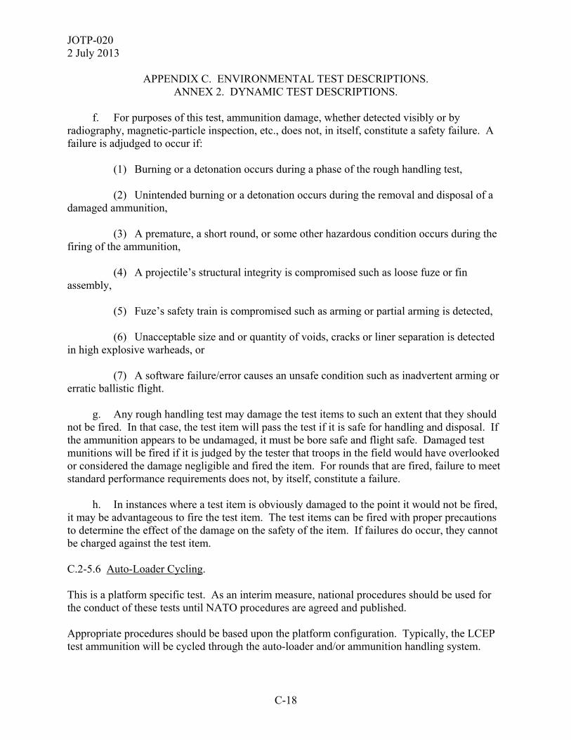
JOTP-020 2 July 2013
C-18
APPENDIX C. ENVIRONMENTAL TEST DESCRIPTIONS. ANNEX 2. DYNAMIC TEST DESCRIPTIONS.
f. For purposes of this test, ammunition damage, whether detected visibly or by radiography, magnetic-particle inspection, etc., does not, in itself, constitute a safety failure. A failure is adjudged to occur if: (1) Burning or a detonation occurs during a phase of the rough handling test, (2) Unintended burning or a detonation occurs during the removal and disposal of a damaged ammunition, (3) A premature, a short round, or some other hazardous condition occurs during the firing of the ammunition, (4) A projectile’s structural integrity is compromised such as loose fuze or fin assembly, (5) Fuze’s safety train is compromised such as arming or partial arming is detected, (6) Unacceptable size and or quantity of voids, cracks or liner separation is detected in high explosive warheads, or (7) A software failure/error causes an unsafe condition such as inadvertent arming or erratic ballistic flight. g. Any rough handling test may damage the test items to such an extent that they should not be fired. In that case, the test item will pass the test if it is safe for handling and disposal. If the ammunition appears to be undamaged, it must be bore safe and flight safe. Damaged test munitions will be fired if it is judged by the tester that troops in the field would have overlooked or considered the damage negligible and fired the item. For rounds that are fired, failure to meet standard performance requirements does not, by itself, constitute a failure. h. In instances where a test item is obviously damaged to the point it would not be fired, it may be advantageous to fire the test item. The test items can be fired with proper precautions to determine the effect of the damage on the safety of the item. If failures do occur, they cannot be charged against the test item. C.2-5.6 Auto-Loader Cycling. This is a platform specific test. As an interim measure, national procedures should be used for the conduct of these tests until NATO procedures are agreed and published. Appropriate procedures should be based upon the platform configuration. Typically, the LCEP test ammunition will be cycled through the auto-loader and/or ammunition handling system.
JOTP-020 2 July 2013
C-19
APPENDIX C. ENVIRONMENTAL TEST DESCRIPTIONS. ANNEX 2. DYNAMIC TEST DESCRIPTIONS.
Guidance for assessing auto-loader shock is given in ITOP 03-2-051. This will incorporate ram-extraction and therefore a separate test will not be necessary in this case. a. Munition Configuration: Unpackaged. b. Test Temperature: Temperature condition the test munitions prior to, and during shock testing. Stabilize all cold munitions to LFT, and all hot munitions to UFT. C.2-6. NON-SEQUENTIAL DYNAMIC TESTS. C.2-6.1 (Logistic) 12 Meter Safety Drop. This mandatory logistic drop test, as described in STANAG 4375, assesses the safety of the AUR when exposed to a free-fall drop which may be encountered during ship loading operations. a. Test Temperature: Temperature condition the munition prior to conducting the logistic drop tests. Stabilize all designated cold munitions to a temperature of -46 °C. Stabilize all designated hot munitions to the packaged SRE temperature. Drop tests should be conducted within 30 minutes of removal from the conditioned environment. b. Munition Configuration: This test should be conducted as a non-sequential, factory-fresh munition packaged in the logistic container. c. Test Procedure: Conduct one handling drop test on each drop test munition from height of 12 meters onto a concrete supported steel surface. The drop test should be conducted in accordance with STANAG 4375. d. Drop Orientation: The test munition is to be released such that it will approximate an initial impact in one of the following orientations: (1) Major axis vertical, nose up. (2) Major axis vertical, nose down. (3) Major axis horizontal. e. The sample size shall be subdivided to ensure at least one impact occurs in each of the most severe orientations in terms of the potential reaction of the munition. C.2-6.2 Parachute Resupply.

JOTP-020 2 July 2013
C-20
APPENDIX C. ENVIRONMENTAL TEST DESCRIPTIONS. ANNEX 2. DYNAMIC TEST DESCRIPTIONS.
a. Munitions may be re-supplied by parachute delivery and are expected to remain S3 following such an event. Per AOP-20, Test E5, high velocity parachute systems may result in impact velocities of 27.4 m/s (90 ft/sec), while the low velocity drop is aligned with the requirement from Def Stan 00-35 (Issue 4). b. Munitions that may be re-supplied by parachute delivery are at risk of a malfunctioning parachute drop scenario and are expected to remain safe for disposal. Per AOP-20, Test E5, malfunctioning parachute systems may result in impact velocities of 45.7 m/s (150 ft/sec). c. Testing may be achieved by directly dropping from an aircraft in accordance with ITOP 07-2-509(1). Parachute delivery may also be simulated using a free-fall drop tailored to give the correct impact velocity, as listed below. C.2-6.2.1 Low Velocity Parachute Drop. This test should be conducted as a non-sequential test on a minimum of three fully live munitions per pallet, including live fuzes where applicable. a. Test Temperature: Temperature condition the munitions prior to the test. Stabilize all designated cold munitions to a temperature of -46 °C. Stabilize all designated hot munitions to the packaged SRE temperature. Drop tests should be conducted within 30 minutes of removal from conditioning. b. Munition Configuration: Conduct this test on packaged and palletized munitions with appropriate parachute drop specific padding/crushable material. The remainder of the pallet should be filled with suitable ballast. c. Test Procedure: Conduct one drop in accordance with AECTP 400, Method 414, from a height of 8 m onto concrete to simulate a Low Velocity Air Drop. The test munition is to be released such that it will approximate an initial impact drop orientation of base down. A laboratory shock test may be applied if it can be demonstrated to produce an equivalent velocity and loading on the munition. C.2-6.2.2 High Velocity Parachute Drop. This test should be conducted as a non-sequential test on a minimum of three munitions with live fuzes (other energetic components may be inert). a. Test Temperature. The high velocity parachute drop is conducted at ambient temperature.
JOTP-020 2 July 2013
C-21
APPENDIX C. ENVIRONMENTAL TEST DESCRIPTIONS. ANNEX 2. DYNAMIC TEST DESCRIPTIONS.
b. Test Configuration. Conduct this test on packaged and palletized munitions with appropriate parachute drop specific padding/crushable material. The remainder of the pallet should be filled with suitable ballast. c. Drop Height. In order to achieve the impact velocity of 27.4 m/s (90 ft/sec), this environment is commonly replicated by a 41 m (135 ft) freefall drop unless specific and validated evidence is presented to the contrary. d. Number of Drops. It is not expected that a munition would be dropped more than once from this extreme height during its service life; thus, only one drop is required. C.2-6.2.3 Malfunctioning Parachute Drop. This test should be conducted as a non-sequential test on a total of three munitions with live fuzes (other energetic components may be inert). a. Test Temperature. The malfunctioning parachute drop is conducted at ambient temperature. b. Test Configuration. Conduct this test on packaged and palletized munitions with appropriate parachute drop specific padding/crushable material. The remainder of the pallet should be filled with suitable ballast. c. Drop Height. In order to achieve the impact velocity of 45.7 m/s (150 ft/sec), this environment is commonly replicated by a 116 m (380 ft) freefall drop unless specific and validated evidence is presented to the contrary. d. Number of Drops. It is not expected that a munition would be dropped more than once from this extreme height during its service life; thus, only one drop is required.
JOTP-020 2 July 2013
C-22
APPENDIX C. ENVIRONMENTAL TEST DESCRIPTIONS. ANNEX 3. ELECTROMAGNETIC ENVIRONMENT EFFECTS TEST DESCRIPTIONS.
C.3-1. HAZARDS OF ELECTROMAGNETIC RADIATION TO ORDNANCE. Conduct the HERO test using guidance in AECTP 500, Category 508, Leaflet 3, and the parameters found in for all LCEP configurations. HERO tests are performed using one complete inert munition with instrumented inert EIDs and/or ESADs. The HERO tests generally use an electric measuring chain (instrumented EIDs) that will collect measured induced stimulus data. The instrumented EIDs have a thermal sensor placed near them to measure the slightest change in temperature, which is then translated into induced current and a safety margin is calculated in accordance with AECTP 500, Category 508, Leaflet 3. In case other EIDs (e.g., electroexplosive devices (EEDs), gap initiators, exploding foil initiators) are used, it is acceptable to conduct tests without instrumentation, but a considerably higher number of units and a theoretical analysis will be required; or the margin must be placed on the test environment for GO-NO-GO testing of live EIDs. Therefore, for non-instrumented devices, six EIDs or ESADs are required for this test per Appendix B, and the analysis or higher test environment is required. C.3-2. ELECTROSTATIC DISCHARGE TESTS. C.3-2.1 Personnel Handling. a. Personnel handling ESD tests are performed using an inert munition which contains inert or live EIDs/ESADs. A minimum of 20 complete sets of EIDs/ESADs are required (see Appendix B). b. Conduct personnel handling ESD tests using guidance in AECTP 500, Category 508, Leaflet 2. The discharge is applied to all connectors (protective covers removed) and electronics accessible during system checks and/or field assembly. ESADs shall be tested while in the functional mode. c. Inspect and test all EIDs/ESADs for activation. C.3-2.2 Helicopter-Borne Transportation. a. Helicopter-borne transportation ESD tests are performed using an inert munition, which contains inert or live EIDs/ESADs. A minimum of 10 complete sets of EIDs/ESADs are required (see Appendix B). b. Conduct helicopter-borne transportation ESD tests using AECTP 500, Category 508, Leaflet 2. c. Inspect and test all EIDs/ESADs for activation.
JOTP-020 2 July 2013
C-23
APPENDIX C. ENVIRONMENTAL TEST DESCRIPTIONS. ANNEX 3. ELECTROMAGNETIC ENVIRONMENT EFFECTS TEST DESCRIPTIONS.
C.3-3. LIGHTNING HAZARD. a. The tests are performed with the munition in the worst case configuration based on analysis of the LCEP scenario. b. One complete live munition is subjected to indirect and direct lightning strike tests. c. Additional indirect or direct lightning tests shall be performed using inert munitions with instrumented inert or live EIDs/ESADs. A minimum of 20 complete sets of EIDs/ESADs (10 for indirect lightning strike and 10 for direct lightning strike) are required to provide adequate data when instrumented components are not available (see Appendix B). d. Perform the lightning strike tests using the parameters found in AECTP 500, Category 508, Leaflet 4.

JOTP-0202 July 2013
C-24
(This page is intentionally blank.)

JOTP-020 2 July 2013
D-1
APPENDIX D. S3 NON-SEQUENTIAL/FIRING TESTS. This document was developed within the international community and is written with primarily references to NATO test procedures to provide a framework for international procurement and test programs. Table G2-1 (Appendix G, Annex 2) provides detailed comparison of similar national and international test standards. Whilst each test standard often has unique requirements, the table does not imply the standards are the same or interchangeable. However, national test standards, or test methods, may be substituted for the international test standard referenced in the JOTP. This appendix provides descriptions of all of the non-sequential and firing tests or assessments required in the S3 Test Programs. Rationale for these tests are provided in Appendix A.
JOTP-020 2 July 2013
D-2
APPENDIX D. S3 NON-SEQUENTIAL/FIRING TESTS. ANNEX 1. PROJECTILE STRENGTH-OF-DESIGN TEST.
D.1-1. PROJECTILE STRENGTH-OF-DESIGN TEST. Strength-of-design tests are conducted with inert-loaded projectiles to verify the projectile structural components can withstand the maximum firing stresses; ten each at UFT and LFT with one additional round set aside for comparison to recovered projectiles. This projectile will not be fired; it can be used as an examination projectile for comparison with recovered projectiles. It can be utilized to check for hardness, sectioned, and examined to verify that physical property requirements are met. D.1-1.1 Method. a. The tube used for this test shall have a minimum of 75% wear life remaining. b. Test projectiles must be inert loaded, if applicable. If cargo projectiles, then cargo must be inert. Stamp a number on each projectile for identification after recovery. c. Make pre-fire dimensional measurements (diameters, hardness weight) on projectiles to be fired. Compare with drawing requirements. If satisfactory proceed with the test. d. Scribe index marks across all projectile joints (if applicable). e. Fire the UFT conditioned projectiles with a propelling charge that will yield (as close to as possible) 4.75 standard deviations above the ESCP. This approach is not greatly different than the historical method of firing at 105% PMP, and either method is acceptable. This can be achieved either by temperature conditioning and/or by providing a special propelling system to develop the required chamber pressure. f. Fire the LFT conditioned projectiles with a propelling charge that will yield (as close to as possible) 4.75 standard deviations above the ESCP. This can be achieved either by temperature conditioning and/or by providing a special propelling system to develop the required chamber pressure. g. Observe the rounds fired to determine where the projectiles impact. The goal is to recover at least 50% of the projectiles. Select the appropriate recovery technique. Recovered projectiles may require sectioning or disassembly. NOTE: Fire additional projectiles as required if insufficient numbers of projectiles are recovered to permit adequate analysis. h. During firing, visually capture the initial flight of each projectile. i. Measure the projectile spin rate, if required, following guidance in ITOP 04-2-811.

JOTP-020 2 July 2013
D-3
APPENDIX D. S3 NON-SEQUENTIAL/FIRING TESTS. ANNEX 1. PROJECTILE STRENGTH-OF-DESIGN TEST.
j. If the munitions under test are cargo-carrying projectiles, a portion of the projectiles should be fired in the ejection mode and the cargo and carrier recovered and examined. D.1-1.2 Data Required. a. General Test Data. (1) Date of test. (2) Test location. (3) Weapon configuration and component serial numbers. (4) Gun tube inspection results (before and after test) and munition history. (5) Surface meteorological data at gun position and at target area if applicable. (6) Aloft meteorological (1000 meters above expected maximum ordinate) data taken at a location along the trajectory. Ideally at the location where trajectory maximum ordinate is expected. b. Round by Round. (1) Time of firing. (2) Munition configuration and lot numbers. (3) Weight of each fuzed projectile and each propelling charge or of each cartridge. (4) Weapon elevation and line of fire. (5) Muzzle velocity. (6) Munition conditioning temperature. (7) Peak or chamber pressure and, if applicable, differential pressures. (8) Projectile seating depth. (9) High speed video or still imagery of projectile exiting tube. (10) Projectile yaw, if applicable.

JOTP-020 2 July 2013
D-4
APPENDIX D. S3 NON-SEQUENTIAL/FIRING TESTS. ANNEX 1. PROJECTILE STRENGTH-OF-DESIGN TEST.
(11) Confirmation of rocket motor ignition or base bleed (if applicable). (12) Fall of shot data. (13) Evidence of excessive coppering, if applicable. (14) Pre and post firing measurements of front and rear bourrelet diameters on recovered projectiles. D.1-1.3 Data Reduction and Analysis. a. For each of the two temperatures, determine the mean and standard deviation of the peak chamber pressure, muzzle velocity, and shot range. b. Review photographs and videos. c. After recovery examine the projectile for the following (impact damage should be separately recorded): (1) Loss or breakup of metal-parts components. (2) Looseness of the driving band. (3) Excessive wear of the driving band. (4) Evidence of filler or propellant gas leakage around joints of multi-piece projectiles. (5) Movement of components with respect to one another as evidenced by misalignment of scribe marks. (6) Engraving around the circumference of the body or evidence of upsetting (failure of cylindrical body in radial expansion caused by axial compression). Some body engraving is acceptable provided the depth is not excessive; however, engraving on the entire circumference is cause for concern. (7) Deformation as evidenced by significant changes in diametrical measurements. d. For cargo-carrying rounds which were fired and ejected, examine and measure the recovered cargo and carrier.

JOTP-020 2 July 2013
D-5
APPENDIX D. S3 NON-SEQUENTIAL/FIRING TESTS. ANNEX 2. PROJECTILE SAFETY IN GUN TEST.
D.2-1. PROJECTILE SAFETY TEST. This test is designed to provide preliminary data on the safety of the test munition. These data are required to give assurance that the test munition can proceed into the more strenuous sequential environmental tests. The pre-firing environmental conditioning test simulates the extreme temperature environments and the severe shocks, bumps, and drops that a munition may receive when: a. Thrown on the bed of a truck or tracked vehicle. b. Transported unsecured over rough terrain. c. Dropped from a tailgate or helicopter. d. Dropped while being loaded onto a vehicle or into a weapon. D.2-1.1 Method. a. A preliminary test is required for projectiles which contain white phosphorus. (1) Orient 10 projectiles/cartridges with their longitudinal axes in a horizontal plane. (2) Mark the test munitions to indicate the upper side for reference during the heating and cooling cycles. (3) Subject them to a 7-day temperature cycle using the Climatic Category A1 of AECTP 200. The 7-day test is followed by a 24-hour post-storage cooling period at 21 °C. (4) Perform radiographic inspection to determine if a side void was established which could lead to projectile unbalance. (5) Uniformly condition the samples to 21 °C for a minimum of 24 hours, then fire with a service charge (highest zone) in an appropriate weapon using a tube with 75% wear remaining life. (6) Measure/collect fall of shot data. (7) Determine whether the unbalance (if any) is sufficient to produce erratic flight. If satisfactory, continue the initial safety test. If unsatisfactory, stop testing, and consult with the developer.
JOTP-020 2 July 2013
D-6
APPENDIX D. S3 NON-SEQUENTIAL/FIRING TESTS. ANNEX 2. PROJECTILE SAFETY IN GUN TEST.
b. Label munition for identification. For semi-fixed munitions, charges must be adjusted after exposure to the sequence. c. Determine which test sequence (from Figures D2-1, D2-2, or D2-3) is required based on the type of munition.
Figure D2-1. Initial Safety Test for Separate Loading Projectiles.

JOTP-020 2 July 2013
D-7
APPENDIX D. S3 NON-SEQUENTIAL/FIRING TESTS. ANNEX 2. PROJECTILE SAFETY IN GUN TEST.
Figure D2-2. Initial Safety Test for Propelling Charges.

JOTP-020 2 July 2013
D-8
APPENDIX D. S3 NON-SEQUENTIAL/FIRING TESTS. ANNEX 2. PROJECTILE SAFETY IN GUN TEST.
Figure D2-3. Initial Safety Test for Cartridges.
JOTP-020 2 July 2013
D-9
APPENDIX D. S3 NON-SEQUENTIAL/FIRING TESTS. ANNEX 2. PROJECTILE SAFETY IN GUN TEST.
d. Conduct the 2.1 m and 1.5 m drops using guidance contained in Appendix C, Annex 2, paragraph C.2-5.4 (using drop heights and packaging configurations as stated in the figures). e. Conduct loose-cargo testing using guidance contained in Appendix C, Annex 2, paragraph C.2-2.5.2. Conduct loose-cargo testing of separate-loading projectiles with lifting plugs installed and torqued to specification values. The loose cargo test for separate-loading projectiles and propelling charges is conducted with half the samples positioned vertically and half horizontally. The loose cargo test for semi-fixed cartridges is done sequentially (10 minutes positioned horizontally and 10 minutes positioned vertically). This is necessary to minimize sample sizes. Loose cargo tests of boxed semi-fixed cartridges for the full 20-minute duration in the vertical or horizontal position are conducted as part of the sequential environmental test. f. Conduct the 7-day temperature cycle using the Climatic Category B3 of AECTP 200. This temperature cycling is designed to stress HE fillings or rocket motors after the rough handling tests. This test should be omitted only in very exceptional circumstances, when there is strong evidence to support the view that such cycling will have no effect on the test munition. g. Following each phase of the environmental sequences, radiographically inspect all test munitions and document any damage. If grommets or obturator bands fail during any phase of the test, they will not be replaced. All separate-loading projectiles, which have been severely damaged at the shock-attenuating or universal lifting plugs, will be discarded. They will not be fired. If a component or explosive munition show signs of separating or tightening, record the amount of movement, and return the munition to its original condition or remove it from the test before testing is resumed. The rough handling tests may damage the test munitions. They will be weapon fired, but only if it is judged by the tester that troops in a tactical environment, using only superficial examination, would have overlooked or considered the damage negligible and fired them. h. In some instances the initial safety test may damage a significant number of test munitions to the point that they should not be fired. This defeats the purpose of the test since the intent was to fire a maximum number of samples. If this occurs, stop the test, and consult with the developer to determine a course of action. i. Separate loading projectiles, shall be fired such that projectile PMP is achieved regardless of its conditioning temperature (UFT or LFT). This can be accomplished by heating a suitable propelling charge, using a special propelling charge designed to produce PMP or adding excess propellant to a service charge to achieve PMP. D.2-1.2 Data Required. a. General Test Data. (1) Date of each test sequence.
JOTP-020 2 July 2013
D-10
APPENDIX D. S3 NON-SEQUENTIAL/FIRING TESTS. ANNEX 2. PROJECTILE SAFETY IN GUN TEST.
(2) Test sequence location. (3) Environmental test equipment description. (4) Test sequence packaging configuration description and photographs. (5) Video of drops and loose cargo tests. (6) Radiographs of test munitions after each test sequence. (7) Photographs and summary descriptions of damaged munitions. (8) Weapon configuration and component serial numbers. (9) Gun tube inspection results (before and after test) and munition history. (10) Surface meteorological data at gun position and at target area if applicable. (11) Aloft meteorological (1000 meters above expected maximum ordinate) data taken at a location along the trajectory. Ideally at the location where trajectory maximum ordinate is expected. b. Round by Round. (1) Time of firing. (2) Munition configuration and lot numbers. (3) Weight of each fuzed projectile and each propelling charge or of each cartridge. (4) Weapon elevation and line of fire. (5) Muzzle velocity. (6) Munition conditioning temperature. (7) Copper Crusher (peak) pressure if applicable. (8) Projectile seating depth. (9) High speed video or still imagery of projectile exiting tube. (10) Projectile yaw, if applicable.

JOTP-020 2 July 2013
D-11
APPENDIX D. S3 NON-SEQUENTIAL/FIRING TESTS. ANNEX 2. PROJECTILE SAFETY IN GUN TEST.
(11) Confirmation of rocket motor ignition or base bleed function (if applicable). (12) Fall of shot data. (13) Evidence of excessive coppering, if applicable. D.2-1.3 Data Reduction and Analysis. a. For each of the two conditioning temperatures, determine the mean and standard deviation of the peak chamber pressure, muzzle velocity, and shot range. b. Review photographs, videos and summary descriptions from environmental as well as firing tests to determine if any safety problems occurred.
JOTP-020 2 July 2013
D-12
APPENDIX D. S3 NON-SEQUENTIAL/FIRING TESTS. ANNEX 3. PRELIMINARY PROPELLING SYSTEM SAFETY TEST.
D.3-1. PRELIMINARY PROPELLING SYSTEM SAFETY TEST. If the test munition is a propelling system, testing must be conducted with the projectile that produces the highest chamber pressure using the highest propelling charge zone. D.3-1.1 Method. a. The propelling charge used for this test shall be representative of the production configuration using the highest charge zone. b. The tube used for this test shall have a remaining wear life as follows: (1) Chromed tubes: Chromed tubes tend not to show appreciable wear throughout their life. Therefore, any tube showing no chrome loss is acceptable. (2) Non-chromed tubes: New tube that has only been proof-fired. If this is not possible, use a tube with the maximum remaining life available and document the life. Minimum remaining life must be no less than 75%. c. If fixed or semi-fixed cartridges are to be tested, drill holes in the cartridge cases such that they correspond to the piezoelectric gauge location on the weapon chamber forward and rear. Create a reference mark on the base of the case that is to align with a corresponding mark on the breech face to ensure alignment of the case holes with the transducers once loaded. d. Service or inert projectiles may be used. Alternate projectiles may be used provided their interior ballistic characteristics and volume intrusion into the propellant bed/cannon chamber are demonstrated to be consistent with the service projectile. e. When using propellants which generate the highest chamber pressure at temperatures other than the UFT or LFT, additional specific testing must be performed. f. Instrumentation/warmer rounds shall be fired at the beginning of each temperature group. Anti-interference and/or warmer round(s) shall be fired between temperature groups. g. Fire 10-round groups at temperatures of LFT, 21 °C, and UFT. h. A consistent rate of fire is required during each temperature series. Usually this will be no more than 10 minutes between rounds. i. In order to check for residue, flash-back, after burn or burning embers, the breech opening shall be automatic (if applicable). Place an infrared camera to record hot activity at the breech.

JOTP-020 2 July 2013
D-13
APPENDIX D. S3 NON-SEQUENTIAL/FIRING TESTS. ANNEX 3. PRELIMINARY PROPELLING SYSTEM SAFETY TEST.
D.3-1.2 Data Required. a. General Test Data. (1) Date of test. (2) Test location. (3) Weapon configuration and component serial numbers. (4) Gun tube inspection results (before and after test) and munition history. (5) Surface meteorological data at gun position and at target area if applicable. (6) Aloft meteorological (1000 meters above expected maximum ordinate) data taken at a location along the trajectory. Ideally at the location where trajectory maximum ordinate is expected. b. Round by Round. (1) Time of firing. (2) Munition configuration and lot numbers. (3) Weight of each fuzed projectile and each propelling charge or of each cartridge. (4) Weapon elevation and line of fire. (5) Muzzle velocity. (6) Munition conditioning temperature. (7) Piezoelectric chamber pressure (pressure vs. time for each transducer). (8) Ignition delay (t2). (9) Action time (t4). (10) Peak negative differential pressure. (11) Copper crusher (peak) pressure if applicable. (12) Projectile seating depth.

JOTP-020 2 July 2013
D-14
APPENDIX D. S3 NON-SEQUENTIAL/FIRING TESTS. ANNEX 3. PRELIMINARY PROPELLING SYSTEM SAFETY TEST.
(13) High speed video or still imagery of projectile exiting tube. (14) Confirmation of rocket motor ignition or base bleed function (if applicable). (15) Evidence of residue, flash-back, after burn or burning embers. (16) Evidence of excessive coppering, if applicable. D.3-1.3 Data Reduction and Analysis. a. For each of the three temperatures, determine the mean and standard deviation of the following: (1) Peak chamber pressure. (2) Muzzle velocity. (3) Initial negative differential pressures. b. If pressure and velocity requirements are not met, contact the appropriate national agencies. c. If ignition delays exceed prescribed limits, the cause must be determined before proceeding with the safety test. d. Follow the procedures of ITOP 04-2-700 to determine if the differential pressures are a matter of concern. If they are, inform the appropriate agencies, and proceed with the safety test only if there is a consensus to do so. If there is no problem, continue with the safety tests of this publication, obtaining differential pressures for the various phases, periodically examining the effect of the tests (from vibration, for example) on differential pressure. e. Plot chamber pressure versus temperature, and from this, obtain a temperature coefficient for pressure (change in pressure per degree change in temperature). Compare this result with the previous temperature-coefficient determinations made during development tests.
JOTP-020 2 July 2013
D-15
APPENDIX D. S3 NON-SEQUENTIAL/FIRING TESTS. ANNEX 4. FINAL PROPELLING SYSTEM SAFETY TEST.
D.4-1. FINAL PROPELLING SYSTEM SAFETY TEST. a. This test is conducted to obtain a maximum chamber pressure and muzzle velocity standard deviation. These values shall be compared with the ESCP and Life Cycle Standard Deviation (LCSD) from the LCEP test. If the results are not significantly different, the data may be combined. If the results are significantly different further testing may be required in consultation in accordance with national practices. b. The recommended test configuration consists of two propellant lots, two firing events, and two gun tubes. Statistically, a two-lot-test provides the best data. However, the statistical analysis of the data (for example, from Annex A of STANAG 4110) can also be applied to the analysis of the results from a One Lot Test, but the ESCP and LCSD should be recalculated based on data from subsequent propellant lots. The trial will consist of 56 rounds conditioned to UFT, or the temperature that produces the maximum chamber pressure and muzzle velocity standard deviation. c. Method. (1) This test is based upon the experimental design methods recommended for ANOVA. It is assumed that data for the analysis will be collected from a single test, although the analysis is still possible using data from a number of separate tests. (2) The test requires the use of two gun tubes and that they are fired concurrently in sequence and hence the weapons are required at the same firing point at the same time. Statistically, a two lot test provides the best data. However, the statistical analysis of the data can also be applied to the analysis of the results from a one lot test but the ESCP and LCSD should be recalculated based on data for subsequent propellant lots (guidance in Annex A of STANAG 4110). (3) During the firing test a steady and consistent rate of fire must be adhered to. Typical rates of fire range from 5 to 10 minutes between rounds. Tables D4-1 and D4-2 outline the two-lot and one-lot test sequences.

JOTP-020 2 July 2013
D-16
APPENDIX D. S3 NON-SEQUENTIAL/FIRING TESTS. ANNEX 4. FINAL PROPELLING SYSTEM SAFETY TEST.
TABLE D4-1. TWO-LOT TEST PROPELLING SYSTEM SAFETY TEST
OCCASION 1 OCCASION 2
Gun Tube 1 Gun Tube 2 Gun Tube 1 Gun Tube 2
Lot 1 Lot 2 Lot 2 Lot 1 Lot 1 Lot 2 Lot 2 Lot 1
rd 1 rd 2 rd 3 rd 4 rd 29 rd 30 rd 31 rd 32 rd 5 rd 6 rd 7 rd 8 rd 33 rd 34 rd 35 rd 36 rd 9 rd 10 rd 11 rd 12 rd 37 rd 38 rd 39 rd 40
rd 13 rd 14 rd 15 rd 16 rd 41 rd 42 rd 43 rd 44 rd 17 rd 18 rd 19 rd 20 rd 45 rd 46 rd 47 rd 48 rd 21 rd 22 rd 23 rd 24 rd 49 rd 50 rd 51 rd 52 rd 25 rd 26 rd 27 rd 28 rd 53 rd 54 rd 55 rd 56
TABLE D4-2. ONE-LOT TEST PROPELLING SYSTEM SAFETY TEST
OCCASION 1 OCCASION 2 OCCASION 3 OCCASION 4
Tube 1 Tube 2 Tube 1 Tube 2 Tube 1 Tube 2 Tube 1 Tube 2
rd 1 rd 2 rd 15 rd 16 rd 29 rd 30 rd 43 rd 44 rd 3 rd 4 rd 17 rd 18 rd 31 rd 32 rd 45 rd 46 rd 5 rd 6 rd 19 rd 20 rd 33 rd 34 rd 47 rd 48 rd 7 rd 8 rd 21 rd 22 rd 35 rd 36 rd 49 rd 50 rd 9 rd 10 rd 23 rd 24 rd 37 rd 38 rd 51 rd 52
rd 11 rd 12 rd 25 rd 26 rd 39 rd 40 rd 53 rd 54 rd 13 rd 14 rd 27 rd 28 rd 41 rd 42 rd 55 rd 56
d. Data Required. (1) General Test Data. (a) Date of test. (b) Test location. (c) Weapon configuration and component serial numbers. (d) Gun tube inspection results (before and after test) and munition history. (e) Surface meteorological data at gun position and at target area if applicable.

JOTP-020 2 July 2013
D-17
APPENDIX D. S3 NON-SEQUENTIAL/FIRING TESTS. ANNEX 4. FINAL PROPELLING SYSTEM SAFETY TEST.
(f) Aloft meteorological (1000 meters above expected maximum ordinate) data taken at a location along the trajectory. Ideally at the location where trajectory maximum ordinate is expected. (2) Round by Round. (a) Time of firing. (b) Munition configuration and lot numbers. (c) Weight of each fuzed projectile and each propelling charge or of each cartridge. (d) Weapon elevation and line of fire. (e) Muzzle velocity. (f) Munition conditioning temperature. (g) Piezoelectric chamber pressure (pressure vs. time for each transducer). (h) Ignition delay (t2). (i) Action time (t4). (j) Peak negative differential pressure. (k) Copper crusher (peak) pressure if applicable. (l) Projectile seating depth. (m) High speed video or still imagery of projectile exiting tube. (n) Confirmation of rocket motor ignition or base bleed function (if applicable). (o) Evidence of residue, flash-back, after burn or burning embers. (p) Evidence of excessive coppering, if applicable. e. Data Reduction and Analysis. (1) For each of the three temperatures, determine the mean and standard deviation of the following:

JOTP-020 2 July 2013
D-18
APPENDIX D. S3 NON-SEQUENTIAL/FIRING TESTS. ANNEX 4. FINAL PROPELLING SYSTEM SAFETY TEST.
(a) Peak chamber pressure. (b) Muzzle velocity. (c) Initial negative differential pressures. (2) Follow the procedures of ITOP 04-2-700 to determine if the differential pressures are a matter of concern. If they are, inform the appropriate agencies, and proceed with the safety test only if there is a consensus to do so. (3) Plot chamber pressure versus temperature, and from this obtain a temperature coefficient for pressure (change in pressure per degree change in temperature). Compare this result with the coefficient computed during the Preliminary Propelling System Safety Test.

JOTP-020 2 July 2013
D-19
APPENDIX D. S3 NON-SEQUENTIAL/FIRING TESTS. ANNEX 5. WORN TUBE SAFETY TEST.
D.5-1. WORN TUBE SAFETY TEST. a. Perform this test to determine that the projectile can successfully withstand the firing stresses in a worn barrel. The main problems associated with worn tubes are: (1) Loss of velocity. (2) Damage to the projectile. (3) Erratic flight. (4) Damage to the electronic or mechanical components of cargo-carrying projectiles (torsional impulse). (5) Evidence of balloting (damage to gun or projectile). b. A worn tube is defined as one that has a level of wear/erosion at the condemnation criteria as specified by the developing nation. Wear is defined as the regular removal of steel from the bore by firing; it may lead either to a circumferential increase in the bore diameter or to ovality. Erosion is defined as an irregular removal of steel from the bore by firing; it is normally seen in chrome-plated barrels where the chrome has been worn away. c. This test is conducted in two phases. During the first phase a series if inert projectiles are fired, some of which are recovered and examined to determine if projectile body or rotating band have been deformed as a result for firing. If the results of the first phase are satisfactory the test can proceed to the second phase. During the second phase a series of tactical projectiles (filled with HE or other hazardous filling) are fired with the PMP charge at UFT and LFT to further assess their performance from a worn tube. d. Method. (1) For this test select a tube that is within the fourth quarter of wear life (less than 25% remaining wear life) such that the tube will not reach condemnation limit by the end of the test. (2) Make pre-fire dimensional measurements (diameters, hardness weight) on projectiles to be fired. Compare with drawing requirements. If satisfactory proceed with the test. (3) Scribe index marks across all projectile joints (if applicable).

JOTP-020 2 July 2013
D-20
APPENDIX D. S3 NON-SEQUENTIAL/FIRING TESTS. ANNEX 5. WORN TUBE SAFETY TEST.
(4) Fire inert fill phase projectiles, temperature conditioned, to UFT and LFT. They shall be fired into an area that will minimize damage at impact (soft sand instead of rocky terrain) and permit projectile recovery. (5) At least 50% of the projectiles shall be recovered for radiographic examination and if necessary disassembly and sectioning, except where munition design makes recovery impractical. (6) If cargo-carrying projectiles are being tested, eject and recover some of the cargo in addition to the carrier during the inert fill phase. (7) If the inert fill phase projectile results are satisfactory, fire the tactical fill phase projectiles. Separate loading projectiles and semi-fixed artillery cartridges are fired with the projectiles conditioned to UFT/LFT with propelling charges that would produce PMP in a new tube. Fixed cartridges are fired with the cartridges conditioned to UFT/LFT. e. Data Required. (1) General Test Data. (a) Date of test. (b) Test location. (c) Weapon configuration and component serial numbers. (d) Gun tube inspection results (before and after test) and munition history. (e) Surface meteorological data at gun position and at target area if applicable. (f) Aloft meteorological (1000 meters above expected maximum ordinate) data taken at a location along the trajectory. Ideally at the location where trajectory maximum ordinate is expected. (2) Round by Round. (a) Time of firing. (b) Munition configuration and lot numbers. (c) Weight of each projectile or cartridge with fuze where applicable.

JOTP-020 2 July 2013
D-21
APPENDIX D. S3 NON-SEQUENTIAL/FIRING TESTS. ANNEX 5. WORN TUBE SAFETY TEST.
(d) Weapon elevation and line of fire. (e) Muzzle velocity. (f) Munition conditioning temperature. (g) Copper crusher (peak) pressure. (h) Projectile seating depth. (i) High speed video or still imagery of projectile exiting tube. (j) Projectile yaw, if applicable. (k) Confirmation of rocket motor ignition or base bleed function (if applicable). (l) Fall of shot data. (m) Evidence of excessive coppering, if applicable. (n) Post firing measurements of front and rear bourrelet diameters and movement of scribe marks on recovered projectiles. (o) Photographs of recovered projectiles. f. Data Reduction and Analysis. (1) After recovery examine the projectiles for the following (impact damage should be separately recorded): (a) Loss or breakup of metal-parts components. (b) Looseness of the driving band. (c) Excessive wear of the driving band. (d) Evidence of filler or propellant gas leakage around joints of multi-piece projectiles. (e) Movement of components with respect to one another as evidenced by misalignment of scribe marks.

JOTP-020 2 July 2013
D-22
APPENDIX D. S3 NON-SEQUENTIAL/FIRING TESTS. ANNEX 5. WORN TUBE SAFETY TEST.
(f) Engraving around the circumference of the body or evidence of upsetting (failure of cylindrical body in radial expansion caused by axial compression). Some body engraving is acceptable provided the depth is not excessive; however, engraving on the entire circumference is cause for concern. (g) Deformation as evidenced by significant changes in diametrical measurements. (h) For cargo-carrying rounds which were fired and ejected, examine and measure the recovered cargo and carrier. 1 For each of the two temperatures and test phases, determine the mean and standard deviation of the peak chamber pressure, muzzle velocity and shot range. 2 Determine range and deflection probable errors. 3 Review photographs and videos.

JOTP-020 2 July 2013
D-23
APPENDIX D. S3 NON-SEQUENTIAL/FIRING TESTS. ANNEX 6. AMMUNITION/GUN INTERFACE TESTS.
D.6-1 HOT GUN COOK-OFF. a. A gun heating trial should have been conducted during its qualification testing. This determines the rate at which the chamber heats up for a stated firing scenario (usually a predetermined number of rounds fired at maximum rate of fire) and the rate at which heat is subsequently dissipated. During the gun heating trial, the temperature of the chamber walls is monitored and recorded (e.g., by using an instrumented munition, thermocouple, or pyrometer). b. During qualification of the energetic material(s) used within the munition, the temperature of ignition will have been determined. This temperature should then be compared with that measured for the chamber wall to determine the likelihood that the energetic material(s) will spontaneously ignite. If the temperature of ignition for the energetic material(s) is high compared with the chamber wall temperature, then cook-off in a hot gun is unlikely. If the temperature of ignition is low, or similar compared with the chamber wall temperature then cook-off in a hot gun is likely. If it is likely that the energetic material(s) used in the munition could feasibly cook-off, then consideration should be given to the test methodology in this annex. D.6-1.1 Instrumentation. Gun instrumented with pressure transducers to provide pressure vs. time if a cook-off occurs. Instrumentation is also needed to determine projectile velocity. D.6-1.2 Method. a. Raise the temperature of the gun to give a chamber wall temperature equal to that determined during the gun heating trial. Heating coils may be used for this. b. Load the munition(s) and close the breech (caution is required due to the hot gun scenario and these operations should be done remotely). c. Wait for one hour, recording time and pressure. d. If cook-off has not occurred within one hour, remotely open breech, and allow gun to cool for a further half hour. If there is no sign of smoke or fume being emitted, the munitions may be removed. If there is smoke or fume present, then the wait period must be extended for another half hour with an open breech or until such time that it is safe to remove the munitions (remotely). e. Test munitions that did not cook-off must be destroyed following the hot gun cook-off test because these munitions have been over-stressed.
JOTP-020 2 July 2013
D-24
APPENDIX D. S3 NON-SEQUENTIAL/FIRING TESTS. ANNEX 6. AMMUNITION/GUN INTERFACE TESTS.
CAUTION: Due to the dangerous nature of this test, all loading and unloading operations must be undertaken remotely. Cook-off of hot propelling charges is likely to result in significant pressures being generated that exceed service pressures. Cook-off of a HE projectile is likely to result in a low-order detonation. D.6-2. SHOCK-ATTENUATING LIFTING PLUG. a. Many artillery projectiles are being assembled and issued with universal flanged shock-attenuating lifting plugs. These plugs protect the nose of the projectile if it is transported as loose cargo or dropped. Small impact forces will cause the plug to bend as the shock is absorbed. High impact forces will cause the plug to snap off leaving a short threaded stub in the nose of the projectile. This stub cannot be easily removed thus preventing the fuzing and firing of projectiles which have been subjected to severe nose impact forces. The troops are instructed to discard all projectiles which have severed plugs. b. The projectile testing performed during life cycle sequential test may not be sufficient to adequately evaluate the safety of the shock-attenuating plug. This is due to the fact that the 45° (base or nose) drop in most instances will not stress the plug (and nose area) to maximum levels. Thus a separate test may be required. c. This test is designed to stress the nose area of the projectile to the maximum limit allowed by the plug. The projectile is then fuzed and fired at extreme temperatures and chamber pressures. The maximum force that can be applied to the plug before it breaks is dependent on the height of the drop and angle of impact. These factors must be determined prior to testing. The most severe angle of impact generally occurs during an angled base drop. This angle can be estimated from the geometry of the plug flange and projectile body or by dropping a projectile with a strain patch on the nose at various base-down angles. The height required to break the plug (at the critical angle) can be determined by dropping (at ambient temperature) a small sample of projectile at various heights onto a steel plate. After the height causing breakage is determined, a height slightly below this value is selected for the supplementary test. The supplementary test is conducted as shown in Figure D6-1. Twenty projectiles each are tested at UCT and 20 projectiles are tested at LCT.
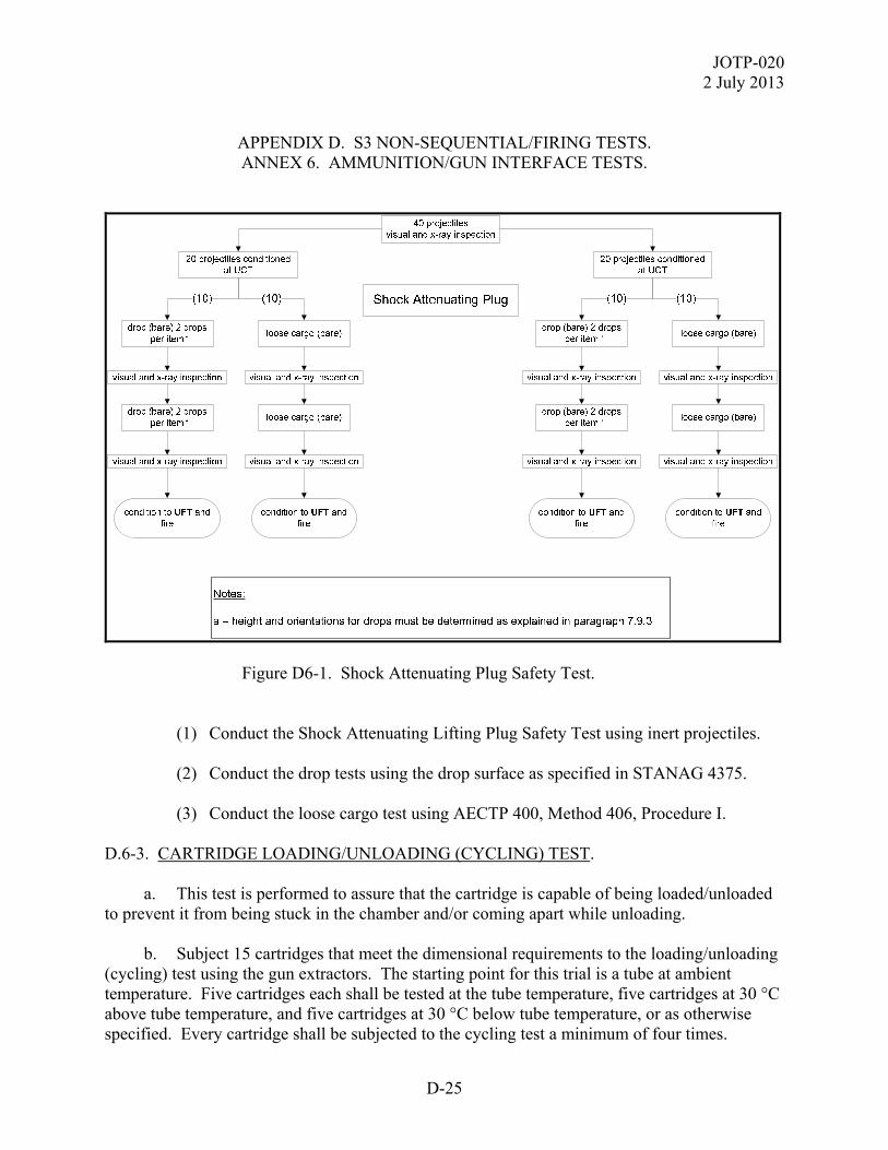
JOTP-020 2 July 2013
D-25
APPENDIX D. S3 NON-SEQUENTIAL/FIRING TESTS. ANNEX 6. AMMUNITION/GUN INTERFACE TESTS.
Figure D6-1. Shock Attenuating Plug Safety Test. (1) Conduct the Shock Attenuating Lifting Plug Safety Test using inert projectiles. (2) Conduct the drop tests using the drop surface as specified in STANAG 4375. (3) Conduct the loose cargo test using AECTP 400, Method 406, Procedure I. D.6-3. CARTRIDGE LOADING/UNLOADING (CYCLING) TEST. a. This test is performed to assure that the cartridge is capable of being loaded/unloaded to prevent it from being stuck in the chamber and/or coming apart while unloading. b. Subject 15 cartridges that meet the dimensional requirements to the loading/unloading (cycling) test using the gun extractors. The starting point for this trial is a tube at ambient temperature. Five cartridges each shall be tested at the tube temperature, five cartridges at 30 °C above tube temperature, and five cartridges at 30 °C below tube temperature, or as otherwise specified. Every cartridge shall be subjected to the cycling test a minimum of four times.

JOTP-020 2 July 2013
D-26
APPENDIX D. S3 NON-SEQUENTIAL/FIRING TESTS. ANNEX 6. AMMUNITION/GUN INTERFACE TESTS.
D.6-4. STICKERS. Sticker testing is conducted with inert projectiles. Sticker testing is done to determine the probability of a projectile lodging or sticking in the bore after the otherwise normal functioning of the ignition system and propelling charge, guidance in ITOP 04-2-804. A sticker creates a potential hazard because of the residual pressure remaining within the chamber.

JOTP-020 2 July 2013
D-27
APPENDIX D. S3 NON-SEQUENTIAL/FIRING TESTS.
ANNEX 7. OTHER GUN FIRING TESTS/ASSESSMENTS. D.7-1. WARHEAD ARENA TRIALS. Warhead arena trials are performed to determine safe separation distances and range safety parameters. These trials should be conducted with non-sequential, factory fresh projectiles unless it can be shown that exposure to thermal and dynamic stresses in the SET Sequence results in an increase in fragmentation distance. Guidance for this test can be found in ITOP 04-2-813. a. Perform this test on a minimum of two (depending on munition type) individual projectiles at ambient temperature. b. Warhead arena trials require the use of the projectile only. However, the tester should evaluate whether ancillary components directly attached to the projectile, either by design or by inadvertent action, could significantly affect the fragment dispersion pattern. c. Place the munition in the instrumented arena and detonate the projectile. d. Determine fragment size, velocity, mass, spatial distribution, and levels of noise and blast pressure. D.7-2. HEALTH HAZARD TESTS/ASSESSMENTS. Health hazard data may be collected during the firing tests. The hazards to be assessed for large caliber gun munitions are described below. D.7-2.1 Impulse Noise and Blast Overpressure. For each new propellant application, including those used in fixed and semi-fixed munitions, a blast overpressure test to measure muzzle blast shall be conducted. These data are required to determine if the shock wave damages structures and/or injures personnel (Blast Overpressure) or damages hearing (Impulse Noise). Both tests can be done together and involves firing at the service charge that gives the greatest pressures, usually at three gun elevations (guidance in TOP 04-2-831). These tests are customarily conducted at ambient temperature. If preliminary data indicate that results are influenced by temperature or charge zone, they must be conducted at the worst predicted conditions. Auditory hazard measurement is addressed by ISO 10843 and MIL-STD-1474. In addition, TR-HFM-090-ANN-H contains a compilation of different blast overpressure methodologies and analysis. In particular, the Stuhmiller model is currently used by many organizations for occupational exposure limits. D.7-2.2 Toxic Chemical Substances.
JOTP-020 2 July 2013
D-28
APPENDIX D. S3 NON-SEQUENTIAL/FIRING TESTS.
ANNEX 7. OTHER GUN FIRING TESTS/ASSESSMENTS. Collect and analyze toxic chemical data during firing tests. Pre-test analysis is recommend to determine most likely combustion products (gaseous and particulate) and their concentrations. The test design should encompass configurations most likely to produce the greatest combustion product hazards. Concentrations for HCN, CO, CO2, SO2, NO, NO2, and Pb shall be measured at the operator’s face and at other strategic locations. The resulting values should be presented in the form of concentration versus time curves and integrated over time to produce the equivalent exposure. The toxic substances under review must be examined by appropriate qualified personnel for potential human (exposure time and dose) health hazards. These hazards shall be evaluated with respect to the envisaged operational environment and on the basis of pertinent national laws and regulations. D.7-2.3 Radiating Energy. During firing tests if applicable, install radiometric sensors in the operator's eye positions (including one at the operator's eyepiece, and any observer location, as applicable) and aim them along the flight path of the munition. Deploy photometrically calibrated detectors for several firings as above. Radiometric data that contain visible spectrum levels may be reduced to provide photometric data. Obtain measurements of radiation capable of causing a thermal injury at the operator's face position. D.7-3. WEAPON DANGER AREAS/ZONES (SURFACE DANGER ZONE). While not considered part of the safety test of munitions, an essential safety related test involves the determination of weapon danger areas (also referred to as surface danger zone) that must be provided when the projectile is employed during training, target practice, and combat. The basic methods for conducting such a test program involve such things as ricochet area, dispersion patterns, fragmentation area, muzzle debris, noise, maximum ordinates, and ranges for various elevations and propellant weights. Obtain guidance from National Authority(ies). D.7-4. THERMAL STABILITY. This test is designed to evaluate the thermal stability of the munition to elevated thermal conditions to determine whether it is too hazardous for transport. The munition may be tested bare or in its logistic container. Gradually raise the temperature of the test munition to 75 ± 2 °C and hold for 48 hours in a chamber equipped with ventilation and explosion proof electrical features. Place a thermocouple either on the outside casing of the unpackaged munition or on the outside casing of the munition that is located near the center of the package. Record the temperature at a minimum of one minute intervals in order to assess any temperature increase that could represent an exothermic reaction. If no reaction occurs, allow the munition to cool to ambient before inspecting for exudation or damage. Additional information is located in United Nations (UN) ST/SC/AC.10/1. The test munition is considered too hazardous for transport if any of the following occur:

JOTP-020 2 July 2013
D-29
APPENDIX D. S3 NON-SEQUENTIAL/FIRING TESTS.
ANNEX 7. OTHER GUN FIRING TESTS/ASSESSMENTS. a. It explodes. b. It ignites. c. It generates colored fumes or odor. d. It experiences a temperature rise exceeding 3 °C. e. The outside casing of the munition or its container is damaged.

JOTP-0202 July 2013
D-30
(This page is intentionally blank.)
JOTP-020 2 July 2013
E-1
APPENDIX E. LEVEL 3 INSPECTION - BREAKDOWN TEST AND CRITICAL ANALYSIS.
This document was developed within the international community and is written with primarily references to NATO test procedures to provide a framework for international procurement and test programs. Table G2-1 (Appendix G, Annex 2) provides detailed comparison of similar national and international test standards. Whilst each test standard often has unique requirements, the table does not imply the standards are the same or interchangeable. However, national test standards, or test methods, may be substituted for the international test standard referenced in the JOTP. E-1. GENERAL INSPECTION. a. All trial munitions shall be subjected to visual inspection and cold radiography (using the LCT from the LCEP) upon their receipt at the trial establishment. For granular or stick type propellants, radiography at ambient temperature will be sufficient. b. Visual inspection shall be carried out between each test within the sequential environmental trial. Additional radiography (ambient or cold depending on the assessed likely failure modes) may be required at key points during the sequential environmental trial where it is suspected there may be an increased likelihood of damage from individual environmental tests. Final inspection at the end of the sequential environmental trial shall consist of visual inspection and cold radiography. c. Non-functioning tests should be carried out as part of routine examination prior to and during the sequential environmental trial. Techniques may include arming then disarming the fuze (only if it is safe to do so) and primer resistance checks on charge systems, and using electronic test sets where applicable. These tests can give important information regarding the continued safety and safe functioning of the munition. d. The condition of any packaging materials and desiccants should also be noted along with the condition of the munition. E-2. BREAKDOWN AND ANALYSIS REQUIREMENTS. a. The following tests are broadly applicable to armor piercing projectiles (tracer), HE shells (main charge, transfer charge, firing train, base bleed unit, and/or rocket motor), carrier shells (payload(s), expulsion charge(s), base bleed, and/or firing train), and propelling charges (main charge, booster charge, transfer charge, igniter, and/or primer). b. The exact requirements for BTCA need to be determined on a case-by-case basis taking into consideration the degree of novelty and/or complexity of the munition system (including projectile, propelling charge and initiation device). They will be determined by known failure modes and life limiting factors for comparable munitions.

JOTP-020 2 July 2013
E-2
APPENDIX E. LEVEL 3 INSPECTION - BREAKDOWN TEST AND CRITICAL ANALYSIS.
c. Prior to commencement of all tests, at least one full munition system (herein referred to simply as the munition) from the same batch(es)/lot(s) as those undergoing the sequential environmental tests should be disassembled and analyzed to identify potential failure modes that may occur. This sets the baseline for comparison against the environmentally stressed munitions. There should also be baseline munitions for the functioning tests. It may also be possible to use manufacturers (material and munition) batch/lot acceptance tests provided these give data equivalent to that required above for baseline purposes. Furthermore, data from development tests may be used for baseline purposes provided the munition is of the same build standard as the test munitions and provides data equivalent to that required for baseline purposes. However, it should be noted that these latter options may not permit comparison against the physical condition of the AURs following the sequential environmental trial. d. Prior to BTCA, it will be necessary to gather material characterization data in accordance with STANAG 4170 to permit comparison with environmentally stressed munitions. Baseline data can be obtained via STANAG 4170 material qualification tests. Alternative sources are material manufacturers batch/lot acceptance data, or material characterization tests carried out on samples taken from munitions set-aside for baseline assessments. It is essential to ensure that the same test procedures used to determine the baseline properties of materials are used during BTCA. e. During disassembly and material extraction, care must be taken to ensure that the extracted samples do not become contaminated (by structural materials or other matter) and/or physically damaged/changed (e.g., compressed, cracked, abraded, etc.). Furthermore, caution must be exercised when unscrewing threaded joints where explosive crystals may be present as a result of environmental exposure, leading to the potential for their initiation from pinching and/or friction. Additionally, Phosphine is likely to be present in the packaging for Red Phosphorus containing projectiles in sufficient quantity to exceed recommended human health exposure limits. Processing (unpacking and disassembly) should only be undertaken in well ventilated areas using appropriate personal protective equipment (respirators etc.). Pyrotechnic compositions containing metal fuels (e.g., magnesium) are prone to oxidation resulting in the production of hydrogen gas, which if present in sufficient quantity, is explosive. Therefore relevant safety procedures must be implemented when processing munitions containing these compositions. f. Small items such as igniters, initiators, etc. pose particular difficulties during disassembly, and it may not be possible to extract sufficient material without damaging the material contained within. In such cases it is acceptable to perform just visual and radiographic examination followed by functioning tests (at extremes of service temperature). In some cases it may be possible to extract sufficient material to perform small scale tests such as volatile content determination and/or appropriate thermal analysis techniques (e.g., heat-flow calorimetry or differential scanning calorimetry). g. The aspects below are provided as an indication of the types of testing required:

JOTP-020 2 July 2013
E-3
APPENDIX E. LEVEL 3 INSPECTION - BREAKDOWN TEST AND CRITICAL ANALYSIS.
(1) Inspection. (a) Prior to disassembly, perform physical integrity and dimensional checks of the munition, sub-systems, energetic materials and structural materials. This can be achieved through visual examination (including photography as required), radiography, CT scan, dye penetrant, bore-scope (for base bleed conduits and other cavities), ultrasonic inspection and/or fluoroscopy both prior to, and following disassembly. Some techniques may be more applicable to structural materials which must also be assessed. Dimensional checks should assess physical dimensions and mass of the all-up-munition, sub-systems and energetic materials to demonstrate compliance with specifications/drawings. Verify the fuze for safety and mode-setting where appropriate. (b) During disassembly, pay particular attention to signs of cracking, surface crystallisation/dusting (e.g., nitramines in warheads), exudation (e.g., nitro-glycerine in propellants or wax in warheads), corrosion, discoloration, wear, missing components, dislodged components, and other damage (e.g., splits in combustible cases). 1 Examine plastics, rubbers, foams, seals, etc. for signs of degradation or uptake of plasticiser. ‘O’ rings should be examined for compression set and that they still meet their specification requirements. 2 Examine the fuze for any signs of degradation. Record all variables and observations. (2) Chemical Tests. (a) Chemical composition, including total volatile matter and moisture content, must be assessed to demonstrate compliance with specifications/drawings. These are applicable to explosives, propellants, pyrotechnics and gunpowders. (b) Chemical stability must be assessed for all energetic materials, although the tests used will be material dependant. The vacuum stability test is particularly applicable for main charge explosives. Chemical stabilizer depletion testing (AOP-48) is applicable for nitrate-ester propellants, with a preference for multi-temperature aging since this gives both stabilizer content and chemical kinetics. (c) Pyrotechnic compositions having a metal fuel are prone to oxidation (e.g., smoke and illuminating compositions). This is brought about by the reaction of the metal fuel with moisture which results in the production of hydrogen. To assess levels of the fuel degradation it is recommended that the free (after oxidation) and total (oxidized and un-oxidized) metal contents of compositions should be determined using suitable analytical techniques. (3) Compatibility Tests.
JOTP-020 2 July 2013
E-4
APPENDIX E. LEVEL 3 INSPECTION - BREAKDOWN TEST AND CRITICAL ANALYSIS.
(a) Chemical/explosive compatibility (per STANAG 4147) between all components with the energetic materials they will be in contact with (both in physical contact and by gas/vapor path) should have been assessed during material qualification and/or design of the munition. This compatibility data shall be presented as a matrix that lists the materials, and for each explosive declares whether there is contact or not with evidence to support the claim of compatibility where contact is expected. (b) During BTCA, any material incompatibilities and/or migration of explosive species are likely to become evident during the Level 1 visual inspection. Any such anomalies observed shall be noted and assessed further to address whether the munition remains safe as defined in AAS3P-1. An example is the migration of species from one energetic material to another (e.g., burn-rate modifiers from one propellant to another). (4) Physical Properties - Explosive Materials. (a) Assessment of flow properties and particle size distribution for granular materials (such as granular propellants and some pyrotechnic compositions), checking for coagulation of granular materials, ‘slump’ (particularly in propellants), bulk cracking and surface cracking/crazing. Optical microscopy is particularly applicable for gunpowders to assess crystal morphology and for potassium nitrate leeching. (b) Thermal analysis methods, especially differential scanning calorimetry, are useful tools that may indicate changes in the material over time and are particularly suited to subsequent comparison during In-Service Surveillance. They are applicable to most explosive materials, especially pyrotechnics, since they can be performed on small samples of material. (5) Mechanical Properties. Mechanical properties (such as tensile/compressive/ shear strength and hardness) of explosive materials must be assessed at the full range of working temperatures for the munition. It will also be necessary to test structural materials at temperature extremes for safety critical munitions, such as cartridge cases or shell bodies, in order to verify design safety margins. Typical methods will include uniaxial tensile test to STANAG 4506 and differential thermal mechanical analysis to STANAG 4540. It may also be necessary to assess fatigue crack growth for some structural materials. The types of testing will ultimately be determined by the type of material being tested. (6) Hazard Properties. (a) Conduct STANAG 4170/AOP-7 small scale material qualification and hazard tests to assess hazard properties for comparison to baseline measurements. These may include, but are not limited to, methods to determine ease of initiation by impact, friction and electrical spark, along with temperature of ignition.
JOTP-020 2 July 2013
E-5
APPENDIX E. LEVEL 3 INSPECTION - BREAKDOWN TEST AND CRITICAL ANALYSIS.
(b) Normally the small scale tests will be sufficient, but larger scale tests may also be required if an issue is identified. The exact methods used would depend upon the type and quantity of material available for the tests but may include ‘gap tests’ and tests to assess velocity of detonation. However, they may ultimately require full scale (i.e. AUR) tests to assess the IM properties of the munition following environmental exposure. (7) Electrical/Electronic Components (if applicable). (a) Where the munition contains electrical sub-assemblies (e.g., electronic fuze, electrical primer) these should be removed during BTCA for inspection and functional checks. Functional checks should be performed on the sub-assemblies. Where this is not possible or does not allow full testing, then the sub-assembly may require further disassembly to permit such testing. (b) Following this, if possible, full disassembly should be conducted for detailed component level inspection. Specific points to observe are broken/loose joints (connectors and solder), damaged/broken components, damaged/broken circuit board tracks, abraded/broken cables/wiring, corrosion, dendritic growth (e.g., ‘tin whiskers’), condition of ‘potting’ compound (if present), and burst batteries. (c) Check electrical resistance of the primer, and verify function using a normal firing pulse. (8) Fuze (Mechanical) Components. (a) Where the munition contains a fuze (mechanical, electrical, or electro-mechanical) this should be removed during BTCA for inspection where possible. (b) If there is any doubt regarding the safe and reliable function of the fuze, or it cannot be demonstrated by alternative means, it may be necessary to carry out tests that simulate the various external stimuli required to arm the fuze (e.g., acceleration, spin). (c) The fuze should be disassembled to determine its internal physical condition and verify its safe condition. (9) Proof Function Of Carrier Shell Payloads. (a) Generally it is better to function carrier shells under proof conditions to assess correct expulsion and function of the payload. Correct function of parachutes, where present, should be verified. The duration over which the effect (e.g., smoke or light) is present should be timed to verify performance.

JOTP-020 2 July 2013
E-6
APPENDIX E. LEVEL 3 INSPECTION - BREAKDOWN TEST AND CRITICAL ANALYSIS.
(b) Smoke and illumination effects should also be verified by static component level firings. Duration/persistence of the effect (a function of burn rate and atmospheric conditions) and other key parameters such as irradiance frequency content (color output to the International Commission on Illumination color coordinates), effectiveness of obscurants compared with their design intent (e.g., visible or infra-red screening).

JOTP-020 2 July 2013
F-1
APPENDIX F. FACILITIES AND INSTRUMENTATION REQUIREMENTS. This document was developed within the international community and is written with primarily references to NATO test procedures to provide a framework for international procurement and test programs. Table G2-1 (Appendix G, Annex 2) provides detailed comparison of similar national and international test standards. Whilst each test standard often has unique requirements, the table does not imply the standards are the same or interchangeable. However, national test standards, or test methods, may be substituted for the international test standard referenced in the JOTP.
TABLE F-1. FACILITIES FOR S3 ASSESSMENT TESTING
FACILITY REQUIREMENTS Firing Range -Can accommodate firing platform or a fixed mount
-Suitable impact areas -Provides protection for personnel and equipment.
Climatic Simulation -able to condition test munitions from -54°C to 71°C. -can produce relative humidity levels between 5% to 95%.
Drop Test
-drop heights of up to 12 m -1,000 kg capacity -impact surface of 7.5 cm thick steel on 60 cm thick concrete -remotely operated
Rough Handling -1,800 kg capacity -2 m by 3 m table size -2.5 cm displacement -1 g acceleration at 4 to 5 Hz -able to condition test munitions from -54°C to 71°C.
Vibration -13,000 kg force 5-2000 Hz -Capable of specimen size 2 m x 2 m x 2 m
Physical Test -magnetic particle -liquid penetrant -projectile centre of gravity, & moment of inertia -radiographic
Material Analysis -As required
Chemical Analysis -refer to AOP-7
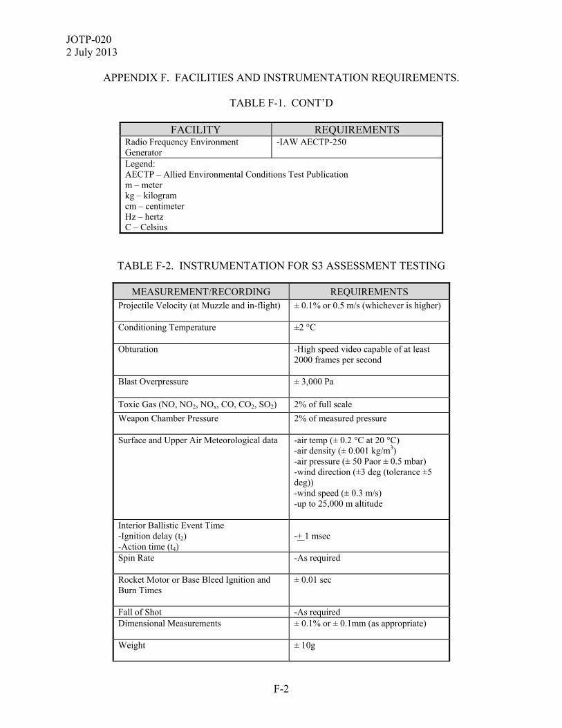
JOTP-020 2 July 2013
F-2
APPENDIX F. FACILITIES AND INSTRUMENTATION REQUIREMENTS.
TABLE F-1. CONT’D
FACILITY REQUIREMENTS Radio Frequency Environment Generator
-IAW AECTP-250
Legend: AECTP – Allied Environmental Conditions Test Publication m – meter kg – kilogram cm – centimeter Hz – hertz C – Celsius
TABLE F-2. INSTRUMENTATION FOR S3 ASSESSMENT TESTING
MEASUREMENT/RECORDING REQUIREMENTS Projectile Velocity (at Muzzle and in-flight) ± 0.1% or 0.5 m/s (whichever is higher)
Conditioning Temperature ±2 °C
Obturation -High speed video capable of at least
2000 frames per second
Blast Overpressure ± 3,000 Pa
Toxic Gas (NO, NO2, NOx, CO, CO2, SO2) 2% of full scale
Weapon Chamber Pressure 2% of measured pressure
Surface and Upper Air Meteorological data -air temp (± 0.2 °C at 20 °C) -air density (± 0.001 kg/m3) -air pressure (± 50 Paor ± 0.5 mbar) -wind direction (±3 deg (tolerance ±5 deg)) -wind speed (± 0.3 m/s) -up to 25,000 m altitude
Interior Ballistic Event Time -Ignition delay (t2) -Action time (t4)
-+ 1 msec
Spin Rate -As required
Rocket Motor or Base Bleed Ignition and Burn Times
± 0.01 sec
Fall of Shot -As required Dimensional Measurements ± 0.1% or ± 0.1mm (as appropriate)
Weight ± 10g
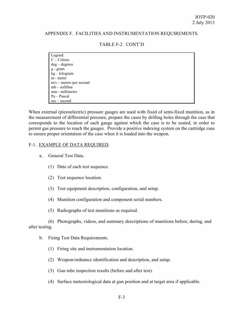
JOTP-020 2 July 2013
F-3
APPENDIX F. FACILITIES AND INSTRUMENTATION REQUIREMENTS.
TABLE F-2. CONT’D
Legend: C – Celsius deg – degrees g - gram kg – kilogram m - meter m/s – meters per second mb – millibar mm - millimeter Pa – Pascal sec – second
When external (piezoelectric) pressure gauges are used with fixed of semi-fixed munition, as in the measurement of differential pressure, prepare the cases by drilling holes through the case that corresponds to the location of each gauge against which the case is to be seated, in order to permit gas pressure to reach the gauges. Provide a positive indexing system on the cartridge case to ensure proper orientation of the case when it is loaded into the weapon. F-1. EXAMPLE OF DATA REQUIRED. a. General Test Data. (1) Date of each test sequence. (2) Test sequence location. (3) Test equipment description, configuration, and setup. (4) Munition configuration and component serial numbers. (5) Radiographs of test munitions as required. (6) Photographs, videos, and summary descriptions of munitions before, during, and after testing. b. Firing Test Data Requirements. (1) Firing site and instrumentation location. (2) Weapon/ordnance identification and description, and setup. (3) Gun tube inspection results (before and after test). (4) Surface meteorological data at gun position and at target area if applicable.

JOTP-020 2 July 2013
F-4
APPENDIX F. FACILITIES AND INSTRUMENTATION REQUIREMENTS. (5) Aloft meteorological (1000 meters above expected maximum ordinate) data taken at a location along the trajectory. Ideally at the location where trajectory maximum ordinate is expected. (6) Date, time of firing, and tube round count. (7) Munition lot numbers. (8) Weight of each munition (and components, if feasible). (9) Weapon elevation and line of fire. (10) Muzzle and downrange velocities, as applicable. (11) Munition conditioning temperature. (12) Peak pressure, chamber pressure, and pressure differential, as applicable. (13) Projectile seating depth, if applicable. (14) High speed video or still imagery of projectile exiting tube. (15) Projectile yaw, if applicable. (16) Confirmation of rocket motor ignition or base bleed (if applicable). (17) Fall of shot data. (18) Evidence of excessive “coppering”, if applicable. (19) Evidence of propellant residue in chamber. (20) Target impact dispersion (TID). (21) Action time and ignition delay, as applicable. F-2. DATA REDUCTION AND ANALYSIS. a. For each of the firing temperatures, determine the mean and standard deviation of the pressure data, and muzzle velocity. b. Review photographs, videos, and summary descriptions from environmental as well as firing tests to determine if any safety problems occurred.

JOTP-020 2 July 2013
G-1
APPENDIX G. ABBREVIATIONS / REFERENCES AND RELATED DOCUMENTS. ANNEX 1. ABBREVIATIONS.
This document was developed within the international community and is written with primarily references to NATO test procedures to provide a framework for international procurement and test programs. Table G2-1 (Appendix G, Annex 2) provides detailed comparison of similar national and international test standards. Whilst each test standard often has unique requirements, the table does not imply the standards are the same or interchangeable. However, national test standards, or test methods, may be substituted for the international test standard referenced in the JOTP. AAS3P Allied Ammunition Safety and Suitability for Service Assessment
Testing Publication AASTP Allied Ammunition Storage and Transport Publication AECTP Allied Environmental Conditions and Test Publication ANEP Allied Navy Engineering Publication ANOVA Analysis of Variance ANSI American National Standards Institute AOP Allied Ordnance Publication AP Allied Publication ARSP Allied Range Safety Publication AUR all-up round BTCA breakdown test and critical analysis C Celsius cm centimeter Def-Stan Defence Standard DP design pressure E3 electromagnetic environmental effects EED electro-explosive device EID electrically initiated device EMOP extreme maximum operating temperature ESAD electronic safe and arm device ESCP extreme service condition pressure ESD electrostatic discharge F frequency F/SF fixed/semi-fixed FR France ft feet

JOTP-020 2 July 2013
G-2
APPENDIX G. ABBREVIATIONS / REFERENCES AND RELATED DOCUMENTS. ANNEX 1. ABBREVIATIONS.
g gram GE Germany GDP gun system design pressure GLGM Gun-Launched Guided Munition GPMP gun system permissible maximum pressure HE high explosive HERO Hazards of Electromagnetic Radiation to Ordnance Hz Hertz IEC International Electrotechnical Commission IEEE Institute of Electrical and Electronics Engineers IM insensitive munition ISO International Organization for Standardization ITOP International Test Operations Procedure JOTP Joint Ordnance Test Procedure KE kinetic energy kg kilogram kJ/mol kilojoule per mole km kilometer LCEP life cycle environmental profile LCSD life cycle standard deviation LCT lower conditioning temperature LFT lower firing temperature m meter m/s meters per second mb millibar MIL-HDBK Military Handbook MIL-STD Military Standard mm millimeter MOP maximum operating pressure NATO North Atlantic Treaty Organization Pa Pascal PDP projectile design pressure PMP permissible maximum pressure PPMP projectile permissible maximum pressure

JOTP-020 2 July 2013
G-3
APPENDIX G. ABBREVIATIONS / REFERENCES AND RELATED DOCUMENTS. ANNEX 1. ABBREVIATIONS.
S3 safety and suitability for service S&A safe and arm (device) SAR safety assessment report SD standard deviation SDP system design pressure sec second SET Sequential Environmental Test SL separate loading SPMP system permissible pressure SRE solar radiation equivalent SRS shock response spectrum STANAG Standardization Agreement T time TB Technical Bulletin TID target impact dispersion TOP Test Operations Procedure TWR time waveform replication UCT upper conditioning temperature UFT upper firing temperature UK United Kingdom UN United Nations UNDEX underwater explosion US United States VERTREP Vertical Replenishment at Sea W/m2 watts per meter squared
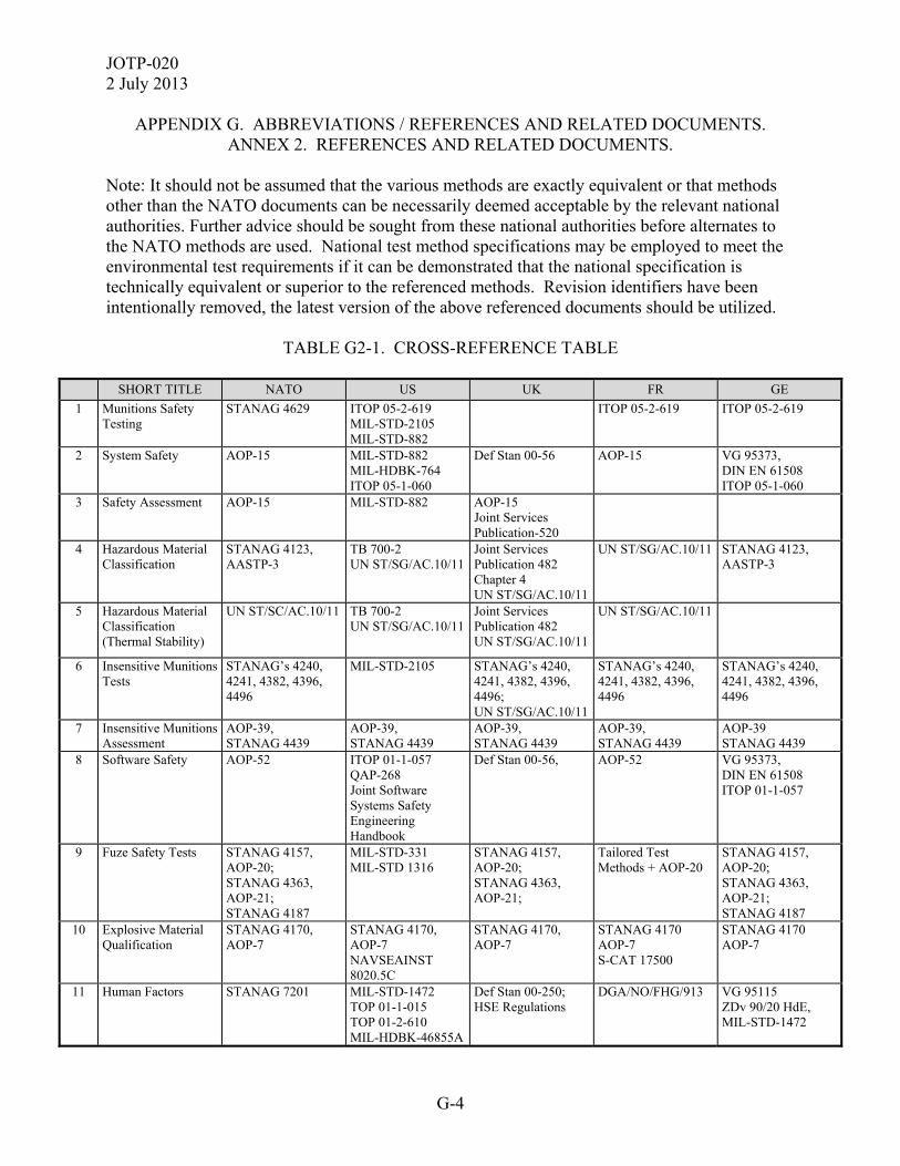
JOTP-020 2 July 2013
G-4
APPENDIX G. ABBREVIATIONS / REFERENCES AND RELATED DOCUMENTS. ANNEX 2. REFERENCES AND RELATED DOCUMENTS.
Note: It should not be assumed that the various methods are exactly equivalent or that methods other than the NATO documents can be necessarily deemed acceptable by the relevant national authorities. Further advice should be sought from these national authorities before alternates to the NATO methods are used. National test method specifications may be employed to meet the environmental test requirements if it can be demonstrated that the national specification is technically equivalent or superior to the referenced methods. Revision identifiers have been intentionally removed, the latest version of the above referenced documents should be utilized.
TABLE G2-1. CROSS-REFERENCE TABLE
SHORT TITLE NATO US UK FR GE
1 Munitions Safety Testing
STANAG 4629 ITOP 05-2-619 MIL-STD-2105 MIL-STD-882
ITOP 05-2-619 ITOP 05-2-619
2 System Safety
AOP-15 MIL-STD-882 MIL-HDBK-764 ITOP 05-1-060
Def Stan 00-56 AOP-15 VG 95373, DIN EN 61508 ITOP 05-1-060
3 Safety Assessment
AOP-15 MIL-STD-882 AOP-15 Joint Services Publication-520
4 Hazardous Material Classification
STANAG 4123, AASTP-3
TB 700-2 UN ST/SG/AC.10/11
Joint Services Publication 482 Chapter 4 UN ST/SG/AC.10/11
UN ST/SG/AC.10/11 STANAG 4123, AASTP-3
5 Hazardous Material Classification (Thermal Stability)
UN ST/SC/AC.10/11 TB 700-2 UN ST/SG/AC.10/11
Joint Services Publication 482 UN ST/SG/AC.10/11
UN ST/SG/AC.10/11
6 Insensitive Munitions Tests
STANAG’s 4240, 4241, 4382, 4396, 4496
MIL-STD-2105
STANAG’s 4240, 4241, 4382, 4396, 4496; UN ST/SG/AC.10/11
STANAG’s 4240, 4241, 4382, 4396, 4496
STANAG’s 4240, 4241, 4382, 4396, 4496
7 Insensitive Munitions Assessment
AOP-39, STANAG 4439
AOP-39, STANAG 4439
AOP-39, STANAG 4439
AOP-39, STANAG 4439
AOP-39 STANAG 4439
8 Software Safety
AOP-52
ITOP 01-1-057 QAP-268 Joint Software Systems Safety Engineering Handbook
Def Stan 00-56,
AOP-52 VG 95373, DIN EN 61508 ITOP 01-1-057
9 Fuze Safety Tests STANAG 4157, AOP-20; STANAG 4363, AOP-21; STANAG 4187
MIL-STD-331 MIL-STD 1316
STANAG 4157, AOP-20; STANAG 4363, AOP-21;
Tailored Test Methods + AOP-20
STANAG 4157, AOP-20; STANAG 4363, AOP-21; STANAG 4187
10 Explosive Material Qualification
STANAG 4170, AOP-7
STANAG 4170, AOP-7 NAVSEAINST 8020.5C
STANAG 4170, AOP-7
STANAG 4170 AOP-7 S-CAT 17500
STANAG 4170 AOP-7
11 Human Factors STANAG 7201 MIL-STD-1472 TOP 01-1-015 TOP 01-2-610 MIL-HDBK-46855A
Def Stan 00-250; HSE Regulations
DGA/NO/FHG/913 VG 95115 ZDv 90/20 HdE, MIL-STD-1472
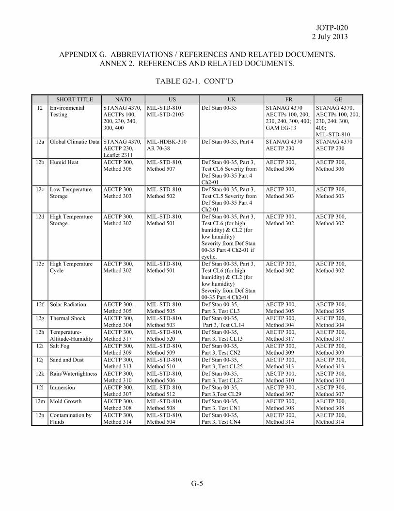
JOTP-020 2 July 2013
G-5
APPENDIX G. ABBREVIATIONS / REFERENCES AND RELATED DOCUMENTS. ANNEX 2. REFERENCES AND RELATED DOCUMENTS.
TABLE G2-1. CONT’D
SHORT TITLE NATO US UK FR GE
12 Environmental Testing
STANAG 4370, AECTPs 100, 200, 230, 240, 300, 400
MIL-STD-810 MIL-STD-2105
Def Stan 00-35 STANAG 4370 AECTPs 100, 200, 230, 240, 300, 400; GAM EG-13
STANAG 4370, AECTPs 100, 200, 230, 240, 300, 400; MIL-STD-810
12a Global Climatic Data STANAG 4370, AECTP 230, Leaflet 2311
MIL-HDBK-310 AR 70-38
Def Stan 00-35, Part 4 STANAG 4370 AECTP 230
STANAG 4370 AECTP 230
12b Humid Heat AECTP 300, Method 306
MIL-STD-810, Method 507
Def Stan 00-35, Part 3, Test CL6 Severity from Def Stan 00-35 Part 4 Ch2-01
AECTP 300, Method 306
AECTP 300, Method 306
12c Low Temperature Storage
AECTP 300, Method 303
MIL-STD-810, Method 502
Def Stan 00-35, Part 3, Test CL5 Severity from Def Stan 00-35 Part 4 Ch2-01
AECTP 300, Method 303
AECTP 300, Method 303
12d High Temperature Storage
AECTP 300, Method 302
MIL-STD-810, Method 501
Def Stan 00-35, Part 3, Test CL6 (for high humidity) & CL2 (for low humidity) Severity from Def Stan 00-35 Part 4 Ch2-01 if cyclic.
AECTP 300, Method 302
AECTP 300, Method 302
12e High Temperature Cycle
AECTP 300, Method 302
MIL-STD-810, Method 501
Def Stan 00-35, Part 3, Test CL6 (for high humidity) & CL2 (for low humidity) Severity from Def Stan 00-35 Part 4 Ch2-01
AECTP 300, Method 302
AECTP 300, Method 302
12f Solar Radiation AECTP 300, Method 305
MIL-STD-810, Method 505
Def Stan 00-35, Part 3, Test CL3
AECTP 300, Method 305
AECTP 300, Method 305
12g Thermal Shock AECTP 300, Method 304
MIL-STD-810, Method 503
Def Stan 00-35, Part 3, Test CL14
AECTP 300, Method 304
AECTP 300, Method 304
12h Temperature-Altitude-Humidity
AECTP 300, Method 317
MIL-STD-810, Method 520
Def Stan 00-35, Part 3, Test CL13
AECTP 300, Method 317
AECTP 300, Method 317
12i Salt Fog AECTP 300, Method 309
MIL-STD-810, Method 509
Def Stan 00-35, Part 3, Test CN2
AECTP 300, Method 309
AECTP 300, Method 309
12j Sand and Dust AECTP 300, Method 313
MIL-STD-810, Method 510
Def Stan 00-35, Part 3, Test CL25
AECTP 300, Method 313
AECTP 300, Method 313
12k Rain/Watertightness AECTP 300, Method 310
MIL-STD-810, Method 506
Def Stan 00-35, Part 3, Test CL27
AECTP 300, Method 310
AECTP 300, Method 310
12l Immersion AECTP 300, Method 307
MIL-STD-810, Method 512
Def Stan 00-35, Part 3,Test CL29
AECTP 300, Method 307
AECTP 300, Method 307
12m Mold Growth AECTP 300, Method 308
MIL-STD-810, Method 508
Def Stan 00-35, Part 3, Test CN1
AECTP 300, Method 308
AECTP 300, Method 308
12n Contamination by Fluids
AECTP 300, Method 314
MIL-STD-810, Method 504
Def Stan 00-35, Part 3, Test CN4
AECTP 300, Method 314
AECTP 300, Method 314

JOTP-020 2 July 2013
G-6
APPENDIX G. ABBREVIATIONS / REFERENCES AND RELATED DOCUMENTS. ANNEX 2. REFERENCES AND RELATED DOCUMENTS.
TABLE G2-1. CONT’D
SHORT TITLE NATO US UK FR GE
12o Aircraft Cargo Decompression
AECTP 300, Method 312
MIL-STD-810, Method 500
Def Stan 00-35, Part 3, Test CL9
AECTP 300, Method 312
AECTP 300, Method 312
12p Vibration Test STANAG 4370, AECTP 400
MIL-STD-810, Method 514
Def Stan 00-35, Part 3, Test M1
STANAG 4370, AECTP 400
STANAG 4370, AECTP 400
12q Vibration Test Schedule Development
STANAG 4370, AECTP 240, Leaflet 2410
MIL-STD-810, Methods 514, 527
Def Stan 00-35, Part 5
STANAG 4370, AECTP 240, Leaflet 2410
STANAG 4370, AECTP 240; ITOP 01-01-050
12r Commercial (Common Carrier) Transportation Vibration
AECTP 400, Methods 401, 421
MIL-STD-810, Method 514, 527
Def Stan 00-35, Part 3, Test M1, Annex A and M2
AECTP 400, Method 401
AECTP 400, Method 401
12s Military Wheeled Vehicle Transportation Vibration
AECTP 400, Methods 401, 421
MIL-STD-810, Methods 514, 527
Def Stan 00-35, Part 3, Test M1, Annex A and M2
AECTP 400, Method 401
AECTP 400, Method 401
12t Restrained Cargo Transport Shock
AECTP 400, Method 403
MIL-STD-810, Method 516, 527
Def Stan 00-35, Part 3, Test M3
AECTP 400, Method 417
AECTP 400, Method 417
12u Fixed Wing Aircraft Cargo Transportation Vibration
AECTP 400, Methods 401, 421
MIL-STD-810, Methods 514, 527
Def Stan 00-35, Part 3, Test M1, Annex A and M2
AECTP 400, Method 401
AECTP 400, Method 401
12v Helicopter Cargo Transportation Vibration
AECTP 400, Methods 401, 421
MIL-STD-810, Method 514, 527
Def Stan 00-35, Part 3, Test M1, Annex A and M2
AECTP 400, Method 401
AECTP 400, Method 401
12w Under Water Explosion (UNDEX)
STANAG 4549 STANAG 4150 ANEP 43
MIL-S-901 ANEP 43
Def Stan 00-35, Part 3, Test M7 (or Test M3).
STANAG 4150
12x Shipboard Vibration AECTP 400, Methods 401, 421
MIL-STD-810, Method 528, 527; MIL-STD-167
Def Stan 00-35, Part 3, Test M1, Annex A and M2
AECTP 400, Method 401
AECTP 400, Method 401
12y Fixed and Rotary Wing Captive Carriage Vibration
AECTP 400, Method 401,420, 421 and AECTP 240 Leaflet 2410
MIL-STD-810, Methods 514, 527
Def Stan 00-35, Part 5 (test spec development) Def Stan 00-35, Part 3, Test M1and M2 (tailored severities)
AECTP 400, Method 401 and AECTP 240 Leaflet 2410
AECTP 400, Method 401 and AECTP 240 Leaflet 2410
12z Gunfire Shock (Time Waveform Replication)
AECTP 400, Methods 405, 417, 421
MIL-STD-810, Method 519, 525, and 527
Def Stan 00-35, Part 3, Test M19 (tailored severities)
AECTP 400, Methods 405, 417, and 421
AECTP 400, Methods 405, 417, and 421
12aa Tactical and Launch Shocks (Shock Response Spectrum)
AECTP 400, Methods 417, 421 and AECTP 240, Leaflet 249-1
MIL-STD-810, Method 516, 527
Def Stan 00-35, Part 3, Test M19 (tailored severities)
AECTP 400, Methods 417, and AECTP 240, Leaflet 249-1
AECTP 400, Methods 417, and AECTP 240, Leaflet 2491
12ab Missile Free Flight Vibration
AECTP 400, Method 401, 421 and AECTP 240 Leaflet 2410
MIL-STD-810, Methods 514, 527
Def Stan 00-35, Part 5
AECTP 400, Method 401 and AECTP 240 Leaflet 2410
AECTP 400, Method 401 and AECTP 240 Leaflet 2410
12ac Packaged Transit Drop AECTP 400, Method 414
MIL-STD-810, Method 516
Def Stan 00-35, Part 3, Test M5
AECTP 400, Method 414
AECTP 400, Method 414
12ad Catapult Launch and Arrested Landing
AECTP 400, Methods 403, 405, 417, and 421
MIL-STD-810 Method 513, 516, and 525
AECTP 400, Methods 403, 405, 417, and 421
AECTP 400, Methods 403, 405, 417, and 421
AECTP 400, Methods 403, 405, 417, and 421

JOTP-020 2 July 2013
G-7
APPENDIX G. ABBREVIATIONS / REFERENCES AND RELATED DOCUMENTS. ANNEX 2. REFERENCES AND RELATED DOCUMENTS.
TABLE G2-1. CONT’D
SHORT TITLE NATO US UK FR GE
13 Unpackaged Handling Drop
STANAG 4375 MIL-STD-810, Method 516
Def Stan 00-35, Part 3, Test M5
STANAG 4375 STANAG 4375
14 Packaged and Unpackaged Safety Drops
STANAG 4375 MIL-STD-810, Method 516
Def Stan 00-35, Part 3, Test M5
STANAG 4375 STANAG 4375
15 Logistic Drop Test (12m drop)
STANAG 4375 MIL-STD-2105 ITOP 04-2-601
STANAG 4375 STANAG 4375 STANAG 4375
16 Parachute Drop AOP-20 MIL-STD-331 ITOP 07-2-509 TOP 04-2-509
Def Stan 00-35, Part 3, Test M5 AP101A 1102-1
AOP-20, MIL-STD-331
17 Dynamic Firing STANAG 4157, AOP-20; STANAG 4363, AOP-21
ITOP 04-2-806 STANAG 4157, AOP-20; STANAG 4363, AOP-21
STANAG 4157, AOP-20
STANAG 4157, AOP-20; STANAG 4363, AOP-21
18 Warhead Minimum Arming Distance
STANAG 4157, AOP-20; STANAG 4363, AOP-21
ITOP 04-2-806 STANAG 4157, AOP-20; STANAG 4363, AOP-21
STANAG 4157, AOP-20
STANAG 4157, AOP-20; STANAG 4363, AOP-21
19 Warhead Arena Test ITOP 04-2-813; MEM NA 00-130ASR-2-1 (Army FM 101-51-3-CD (EM 0260))
ITOP 04-2-813 ITOP 04-2-813; TL 1300-0011 Part 2, BWB WM VI 2 Hdb. Munitionsbewertung A 1981
20 Weapon Danger Area STANAG 2240, 2401, ARSP-1 Vol I and II, STANAG 2470, ARSP-2, Vol. 1
ITOP 05-2-505
STANAG 2240, 2401, ARSP-1 Vol I and II, STANAG 2470, ARSP-2, Vol. 1
TTA206 STANAG 2921
STANAG 2240, 2401, ARSP-1 Vol I and II, STANAG 2470, ARSP-2, Vol. 1; ZDv 44/10; ITOP 05-2-505
21 Rocket Motor Static Firing ITOP 05-2-500 ITOP 05-2-500 Def Stan 07-85
TL1376-0701, ITOP 05-2-500, AA WTD 91 07-520-004-002
22 Rocket Motor Case Burst ITOP 05-2-621 ITOP 05-2-621 ITOP 05-2-621, VA WTD 91 07-330-16
23 Motor Case Burst Probability
ARO Report 75-2 SMC-S-001
Def Stan 07-85
24 Health Hazards TOP 06-2-507 TOP 10-2-508 OPNAVINST 5100.19E and OPNAVINST 5100.23G
HSE Regulations

JOTP-020 2 July 2013
G-8
APPENDIX G. ABBREVIATIONS / REFERENCES AND RELATED DOCUMENTS. ANNEX 2. REFERENCES AND RELATED DOCUMENTS.
TABLE G2-1. CONT’D
SHORT TITLE NATO US UK FR GE
25 Toxic Gas / Materials ITOP 05-2-502 HSE Regulations Erl. BMVg InSan I4-42-19-01 ITOP 05-2-502
26 Laser Hazards STANAG 3606, ARSP-4
TB MED 524 MIL-HDBK-828
Joint Services Publication 390. HSE Regulations. Control of Artificial Optical Radiation at Work Regulations.
STANAG 3606, ARSP-4
STANAG 3606, ARSP-4
27 Ionizing Radiation Hazards TOP 03-2-711 HSE Regulations
28 Electronic Equipment Hazards
MIL-HDBK-45 Def Stan 00-10 HSE Regulations
29 Radiofrequency Health Hazards
STANAG 2345 TOP 03-2-616 OP3565 Vol. 1 DOD 6055.11
Joint Services Publication 392 Leaflet 35
ENV 501661 ENV 50061
DIN VDE-0848. T.1-4, DIN VDE-0848. T.2
30 Acoustic Noise MIL-STD-1474 ISO 10843: 1997
Def Stan 00-27 HSE Regulations
AT-83/27/28 ZDv 90/20 VM Blatt 1993
31 Blast Overpressure STANAG 4569 with references. Final Report RTO-HFM-089, -090, -148 TR-HFM-090-ANN-H
ITOP 04-2-822 DOD 6055.9-STD
Consignes et instructions relatives à l'enregistrement et à l'exploitation des bruits d'armes et des bruits de détonation
Vorschriften und Richtlinien zur Registrierung und Auswertung von Waffen und Detonationsknallen and STANAG 4569 with references. Final Report RTO-HFM-089, -090, -148
32 Electromagnetic Environmental Effects (tests)
STANAG 4370, AECTP 500
MIL-STD-464 TOP 01-2-511 MIL-STD-461
Def Stan 59-411
GAM DRAM 02
STANAG 4370, AECTP 500
33 Electromagnetic Environmental Effects (environment description)
STANAG 4370, AECTP 250, Leaflet 258
MIL-STD-464 MIL-HDBK-235
Def Stan 59-411
GAM DRAM 01 STANAG 4370, AECTP 250, Leaflet 258
34 Electromagnetic Environmental Effects (HERO)
STANAG 4370, AECTP 508 Leaflet 3
MIL-STD-464 MIL-HDBK-240 JOTP-061 OP3565 Vol. 2
Def Stan 59-114 Def Stan 59-411
GAM DRAM 02
STANAG 4370, AECTP 508, Leaflet 3
35 Electrostatic Discharge (ESD) Environmental Test
STANAG 4370, AECTP 250, Leaflet 253; AECTP 508, Leaflet 2
MIL-STD-464 JOTP-062
Def Stan 59-411
GAM DRAM 01 GAM DRAM 02
STANAG 4370, AECTP 250, Leaflet 253
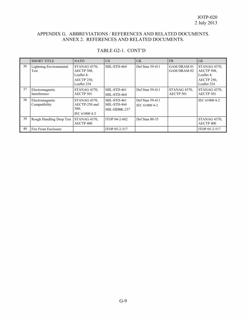
JOTP-020 2 July 2013
G-9
APPENDIX G. ABBREVIATIONS / REFERENCES AND RELATED DOCUMENTS. ANNEX 2. REFERENCES AND RELATED DOCUMENTS.
TABLE G2-1. CONT’D
SHORT TITLE NATO US UK FR GE
36 Lightning Environmental Test
STANAG 4370, AECTP 508, Leaflet 4; AECTP 250, Leaflet 254
MIL-STD-464
Def Stan 59-411
GAM DRAM 01 GAM DRAM 02
STANAG 4370, AECTP 508, Leaflet 4; AECTP 250, Leaflet 254
37 Electromagnetic Interference
STANAG 4370, AECTP 501
MIL-STD-461 MIL-STD-464
Def Stan 59-411 STANAG 4370, AECTP 501
STANAG 4370, AECTP 501
38 Electromagnetic Compatibility
STANAG 4370, AECTP-250 and 500; IEC 61000 4-2
MIL-STD-461 MIL-STD-464 MIL-HDBK-237
Def Stan 59-411 IEC 61000 4-2
IEC 61000 4-2
39 Rough Handling Drop Test STANAG 4370, AECTP 400
ITOP 04-2-602 Def Stan 00-35 STANAG 4370, AECTP 400
40 Fire From Enclosure ITOP 05-2-517 ITOP 05-2-517

JOTP-0202 July 2013
G-10
(This page is intentionally blank.)

JOTP-020 2 July 2013
Comments, suggestions, or questions on this document should be addressed to Range Infrastructure Division (CSTE-TM), US Army Test and Evaluation Command, 2202 Aberdeen Boulevard, Aberdeen Proving Ground, Maryland 21005-5001; or e-mailed to:
Since contact information can change, you may want to verify the currency of this address information using the ASSIST Online database at http://assist.daps.dla.mil. This document is identified by the accession number (AD No.) printed on the first page.