report for arrow energy major pipelines · the study was based on the requirements of as 2885.1...
TRANSCRIPT

This document may only be used by GHD’s client for the purpose for which it was commissioned and in accordance with the Terms of Engagement for the commission.
Unauthorised use of this document in any form whatsoever is prohibited.
Report for ARROW Energy Major Pipelines
Initial Safety Management Study
ABP No: 08-GHD-02-0006
REV 0
Rev No.
Author Reviewer Approved for Issue
Name Signature Name Signature Date
A J Doyle P Wheelwright PW B Jinks BJ 07/09/11
B J Doyle P Wheelwright PW B Jinks BJ 19/09/11
C R Turna J Doyle JD P Nasehmanesh PN 04/10/11
0 R Turna J Doyle P Nasehmanesh
20/10/11

08-GHD-02-0006 - Arrow Energy Major Pipelines - Initial Safety Management Study
Contents
1. Summary 1
2. Project Description 3
2.1 Pipeline 3
2.2 Pipeline Facilities and Stations 5
3. Location Analysis 6
3.1 Measurement Length 6
3.2 Location Classes 6
3.3 Location Analysis Results 9
4. Risk Identification 13
4.1 Penetration Resistance 13
4.2 No Rupture 13
4.3 Energy Discharge Rate 13
4.4 High Consequence Areas 14
4.5 Environmental and Land Constraints 14
5. Threat Analysis and Safety Management Study 15
5.1 Overlay Threats 15
5.2 Location Specific Threats 16
5.3 External Interference 16
6. Proposed Pipeline Risk Strategy 17
6.1 Overlay Threats 17
6.2 Location Specific Threats 19
7. Actions 23
8. Conclusions 27
9. Disclaimer 28
08-GHD-02-0006 - Arrow Energy Major Pipelines - Initial Safety Management Study
Table Index Table 1 Radiation Zones 6
Table 2 Industrial and Heavy Industrial Location Class 11
Table 3 CIC Location Class 11
Table 4 Energy Discharge Rates 14
Table 5 Actions from Workshop 23
Table 6 General Actions 25
Figures Figure 1 Locations Classes - Visual Guide
Appendices A ABP and ASP Pipelines Route Map (for Initial SMS – Alignment
Rev D)
B Assumptions for SMS and Conclusion of Preliminary Calcs
C Workshop Attendance Record
D SMS Location and Threat Analysis Table
E Wall Thickness Calculation Report
F Pipeline Preliminary Walk Through
G General Action Items Closed Out

08-GHD-02-0006 - Arrow Energy Major Pipelines - Initial Safety Management Study 1
1. Summary
It is a requirement of AS 2885.1 to undertake an Initial Safety Management Study (Initial SMS) in the
preliminary design phase for a high-pressure gas pipeline. The Initial SMS is conducted in order to
determine high consequence events and their proposed controls, and to provide sufficient information to
stakeholders in the process of regulatory approvals for the project.
The Initial SMS workshop for the Arrow Bowen Pipeline (ABP) was held on 25 and 26 August 2011 in the
Arrow Energy offices in Brisbane. The workshop was attended by the pipeline proponents (Arrow
Energy), a GIS operator (Arrow Energy) and pipeline engineers (GHD). The workshop attendance record
is attached in Appendix C.
The study was based on the requirements of AS 2885.1 2007. The following parameters were considered
for the study:
Basic pipeline design parameters.
Location Class assessments including definition of high consequence areas.
Typical threats in typical locations.
Location specific threats, particularly in high consequence areas.
Radiation contours for 4.7 and 12.6 kW/m2 in the event of full bore rupture.
The study started with a location analysis, based on pipeline route alignment established on the ABP GIS
and various GIS data including aerial imagery and topographic maps of the area along the alignment.
The version of the pipeline route alignment/GIS data that was used for the Initial SMS is referred to as
“Revision D”.
All KPs determined in the initial SMS workshop are correlated with the “Revision D” alignment, and are
referred to as “AB” in the Arrow Energy approved designation.
The location analysis produced a list of features along the route with associated possible threats.
The threats were identified as location-specific, length-specific and overlay threats (which correspond to
the whole pipeline route). Possible protective measures (both procedural and physical) and further
actions were proposed which would need to be completed and finally determined in the further design
and pipeline route adjustment.
The Location Class along the ABP has been designated as predominantly rural (R1).
Due to the presence of a school and kindergarten within the measurement length at AB 465, the location
class is designated as T1 with a Secondary location class-Sensitive (S) at this location.
The requirements for T1, S and Industrial locations include compliance to ‘no rupture’ criteria, considering
all identified credible threats, which means installation of no rupture/heavy wall pipe in these areas (refer
to Appendix E). The requirements for Heavy Industrial include compliance to no rupture criteria where
pipeline failure would create potential for consequence escalation. The SMS concluded that Heavy
Industrial locations along the ABP were not of high consequence and as such did not warrant the ‘no
rupture’ criteria.

08-GHD-02-0006 - Arrow Energy Major Pipelines - Initial Safety Management Study 2
The major general threats identified in the Initial SMS study include:
Contour forming for agricultural land.
Blade ploughing.
Third party interference by excavation or construction activities.
Failure of maintenance activities on gas and oil pipelines adjacent to the ABP.
Mining land subsidence.
Induced voltages from parallel overhead high-voltage power lines.
The actions resulting from the Initial SMS can be summarised as follows:
Further investigation of land use in terms of proposed developments, power generating and industrial
and mining facilities, in order to determine a potential impact on the pipeline, and assess the
consequence of pipeline failure.
Determine the areas subject to flooding and inundation through further studies and site surveys.
Further investigate the impact that some overlay threats, in particular blade ploughing and land
contouring, may have on the pipeline in order to determine the appropriate protection measures
(primarily depth of cover).
The safety management study process will therefore be continued through further design and formalised
within the detailed safety management study process.
The future detailed safety management study shall determine exact physical and procedural measures,
assess whether these measures eliminate the threat, assign consequence and likelihood values to non-
eliminated threats, determine the risk ranking and assign appropriate risk treatment actions.

08-GHD-02-0006 - Arrow Energy Major Pipelines - Initial Safety Management Study 3
2. Project Description
Arrow Energy (the Principal), is proposing to develop a pipeline network in central eastern Queensland (a
copy of the route map is attached as Appendix A) that will deliver coal seam gas from its gas fields in the
Bowen and Surat Basins to a proposed LNG facility to be located on Curtis Island near Gladstone.
The proposed network will be approximately 1,200 km long and will incorporate scraper stations and
intermediate mainline valves.
A pipeline licence has been granted for the major part of the proposed pipeline from the Surat Basin to
the facilities on Curtis Island.
No part of the proposed pipeline from the Bowen Basin has yet been assessed and this preliminary
engineering is associated with the full extent of approximately 610 km of pipeline length.
The ABP system will consist of a DN800 (32”), Class 600 buried steel pipeline. For the purpose of the
Initial SMS an operational case of a single pipeline, with full capacity/base load being supplied from
Bowen, was considered.
This report also considers a possible future upgrade of the ABP to DN1050 (42”) pipe diameter and the
pipeline design parameters are reflected in section 2.1.1 below.
However the Initial ABP SMS workshop was based on the current DN800 pipeline diameter.
A pipeline schematic drawing and the overall route map are attached in Appendix A.
2.1 Pipeline
The pipeline design parameters listed below are preliminary and are subject to change based on required
gas quantities, design work in the future and outcomes from the further detailed safety management
studies.
In particular:
Potential further pipeline route optimisations and adjustments will be considered.
The pipeline diameter has been nominated as DN800, based on different design flow cases.
For the purpose of the Initial SMS the option of DN800 pipe diameter with maximum allowable operating
pressure (MAOP) of 10.2 MPa was used, as it presents a conservative case in terms of radiation contour
and energy discharge rate in the event of pipeline rupture.
2.1.1 ABP Mainline
The ABP route runs from near Glenden north of Moranbah to a new Gathering Hub where the ABP
intersects with the Arrow Surat Pipeline serving the Surat Basin. Preliminary pipeline design parameters
used during the SMS were:
Diameter DN800
Pressure Design Factor 0.8
Pipe Grade API 5L X70

08-GHD-02-0006 - Arrow Energy Major Pipelines - Initial Safety Management Study 4
Standard Wall Pipe Thickness R1/R2 10.7 mm (Notes 1, 4)
High Consequence Heavy Wall Pipe Thickness 12.5 mm (Notes 2, 4, 7)
Rail Crossing Heavy Wall Pipe Thickness 14.9 mm (Notes 3, 4)
Road crossing Heavy Wall Pipe Thickness 13.8 mm (Notes 3, 5, 4)
Pipeline Assemblies 12.8 mm (Notes 6, 7)
Maximum Allowable Operating Pressure (MAOP) 10.2 MPa
Length 478 km approx.
Diameter DN1050 (possible upgrade)
Pressure Design Factor 0.8
Pipe Grade API 5L X70
Standard Wall Pipe Thickness R1/R2 14.0 mm (Notes 1, 4)
High Consequence Heavy Wall Pipe Thickness 14.5 mm (Notes 2, 4, 7)
Rail Crossing Heavy Wall Pipe Thickness 19.6 mm (Notes 3, 4)
Road crossing Heavy Wall Pipe Thickness 18.0 mm (Notes 3, 5, 4)
Pipeline Assemblies 16.8 mm (Notes 6, 7)
Maximum Allowable Operating Pressure (MAOP) 10.2 MPa
Length 478 km approx.
For a complete list of assumptions used for the SMS and conclusion of preliminary calculations, refer to
Appendix B.
Notes:
1. Based on pressure containment with Fd = 0.8. Occasional vehicle crossings and other criteria not
considered.
2. Excludes design for S and T2 areas.
3. Depending on quantities required, consider rationalising the high consequence road crossing and rail
crossing heavy wall materials.
4. Other wall thickness criteria, such as fatigue, not considered.
5. For designated, not occasional crossings.
6. Based on pressure containment with Fd = 0.67.
7. Depending on quantities required, consider rationalising the high consequence heavy wall and pipeline
assemblies materials.

08-GHD-02-0006 - Arrow Energy Major Pipelines - Initial Safety Management Study 5
2.2 Pipeline Facilities and Stations
The pipeline facilities will comprise the following:
Mid-point scraper station and main line valves (locations to be determined).
Custody Transfer Metering Station at the connection to the Gas Gathering Hub.

08-GHD-02-0006 - Arrow Energy Major Pipelines - Initial Safety Management Study 6
3. Location Analysis
The location analysis is a structured assessment of the land through which a pipeline passes. The
objective is to systematically identify land use and population density, providing important information on
any activities that potentially pose a threat to pipeline integrity, and thus present a risk to the asset and/or
the community. The location analysis determines the location class for this pipeline.
3.1 Measurement Length
AS 2885.1 requires a “measurement length” to be calculated. The land within a measurement length
along the pipeline route is assessed for a particular location class.
The measurement length is the radius of the 4.7 kW/m2 radiation contour for a full bore rupture, calculated
in accordance with API RP 521. This radiation will cause injury after 30 seconds exposure.
The main determinant of radiation contour is pipeline pressure and pipeline diameter.
The radiation contour has been determined as listed in Table 1 below:
Table 1 Radiation Zones
Pipeline Approximate Radiation Zone (m) for 4.7 kW/m2
DN800 – 10.2 MPa (Main Line) 1,100
DN1050 – 10.2 MPa (possible upgrade) 1,250
The radiation contour zone of 1,100 m for DN800 and 1,250 m for DN1050 (possible upgrade) has been
used for both the mainline and the lateral locations – for consistency. This is a conservative approach, as
the laterals are likely to be of smaller diameter.
The gas composition used for the modelling was based on the coal seam methane gas composition
provided for the initial SMS for the SGP.
3.2 Location Classes
Location classes as specified in AS 2885.1 Clause 4.3.4 and Clause 4.3.5 are defined below.
3.2.1 Primary Location Class
The pipeline route shall be classified into one of the Primary Location Classes R1, R2, T1 and T2 as
defined below.
RURAL (R1): Land that is unused, undeveloped or is used for rural activities such as grazing, agriculture
and horticulture. Rural applies where the population is distributed in isolated dwellings. Rural includes
areas of land with public infrastructure serving the rural use; roads, railways, canals, utility easements.
RURAL RESIDENTIAL (R2): Land that is occupied by single residence blocks typically in the range 1 ha
to 5 ha or is defined in a local land planning instrument as rural residential or its equivalent. Land used for
other purposes but with similar population density shall be assigned Rural Residential location class.

08-GHD-02-0006 - Arrow Energy Major Pipelines - Initial Safety Management Study 7
Rural Residential includes areas of land with public infrastructure serving the Rural Residential use;
roads, railways, canals, utility easements.
NOTE: In Rural Residential societal risk (the risk of multiple fatalities associated with a loss of containment) is not a dominant design
consideration.
RESIDENTIAL (T1): Land that is developed for community living. Residential applies where multiple
dwellings exist in proximity to each other and dwellings are served by common public utilities. Residential
includes areas of land with public infrastructure serving the residential use; roads, railways, recreational
areas, camping grounds/caravan parks, suburban parks, small strip shopping centres. Residential land
use may include isolated higher density areas provided they are not more than 10% of the land use. Land
used for other purposes but with similar population density shall be assigned Residential location class.
HIGH DENSITY (T2): Land that is developed for high density community use. High Density applies where
multi storey development predominates or where large numbers of people congregate in the normal use
of the area. High Density includes areas of public infrastructure serving the High Density Use; roads,
railways, major sporting and cultural facilities and land use areas of major commercial developments;
cities, town centres, shopping malls, hotels and motels.
NOTE: In Residential and High Density areas the societal risk associated with loss of containment is a dominant consideration.
In Rural and Rural Residential areas, consideration shall be given to whether a higher location class may
be necessary at any location where a large number of people may be present for a limited period.
NOTE: Examples include roads subject to heavy traffic congestion and sports fields.
3.2.2 Secondary Location Class
Location classes S, CIC, I, HI and W are subclasses that may occur in any primary location class. The
affected length is generally less than the length of the primary location class. Where the land use through
which the pipeline route passes is identified as S, CIC, I, HI or W the requirements of the primary location
class (R1, R2, T1, T2) shall be applied together with additional consideration and additional requirements
established for the S, CIC, I or W location class, as follows:
SENSITIVE USE (S): The Sensitive Use location class identifies land where the consequences of a
failure may be increased because it is developed for use by sectors of the community who may be unable
to protect themselves from the consequences of a pipeline failure. Sensitive uses are defined in some
jurisdictions, but include schools, hospitals, aged care facilities and prisons. Sensitive Use location class
shall be assigned to any portion of pipeline where there is a sensitive development within a measurement
length. It shall also include locations of high environmental sensitivity. The design requirements for high
density shall apply.
NOTE: In Sensitive Use areas, the societal risk associated with loss of containment is a dominant consideration.
INDUSTRIAL (I): The Industrial location class identifies land that poses a different range of threats
because it is developed for manufacturing, processing, maintenance, storage or similar activities or is
defined in a local land planning instrument as intended for light or general industrial use. Industrial applies
where development for factories, warehouses, retail sales of vehicles and plant predominates. Industrial
includes areas of land with public infrastructure serving the industrial use. Industrial location class shall be
assigned to any portion of pipeline where the immediately adjoining land use is industrial. The design requirements for residential shall apply.

08-GHD-02-0006 - Arrow Energy Major Pipelines - Initial Safety Management Study 8
NOTE: In Industrial use areas the dominant consideration may be the threats associated with the land use or the societal risk
associated with the loss of containment.
HEAVY INDUSTRIAL (HI): Sites developed or zoned for use by heavy industry or for toxic industrial use
locations shall be considered classified as Heavy Industrial. They shall be assessed individually to assess
whether the industry or the surroundings include features that:
(i) Contain unusual threats to the pipeline, or
(ii) Contain features that may cause a pipeline failure to escalate either in terms of fire, or for the
potential release of toxic or flammable materials into the environment.
Depending on the assessed severity the design, requirements of R2, T1 or T2 shall be applied.
NOTE: In Heavy Industrial use areas the dominant consideration may be the threats associated with the land use or a range of
location specific risks associated with the loss of containment.
COMMON INFRASTRUCTURE CORRIDOR (CIC): Land defined as a Common Infrastructure Corridor
(CIC), or which because of its function results in multiple (more than one) parallel infrastructure
development within a common easement or reserve, or in easements which are in close proximity.
CIC classification includes pipelines within reserves or easements for roads, railways, powerlines, buried
cables, or other pipelines.
NOTE: In CIC areas the dominant consideration may be the threats associated with the land use by other infrastructure operators or
the higher consequences of loss of containment associated with increased transient population (e.g. roads) or other parallel
infrastructure.
SUBMERGED (W): Land that is continuously or occasionally inundated with water to the extent that the
inundation water, or activities associated with it, is considered a design condition affecting the design of
the pipeline. Pipeline crossings of lakes, estuaries, harbours, marshes, flood plains and navigable
waterways are always included. Pipeline crossings of non-navigable waterways, rivers, creeks, and
streams, whether permanent or seasonal, are included where they meet the design criterion.
The Submerged class extends only to the estimated high water mark of the inundated area.
NOTE: The Submerged class refers only to onshore pipelines designed to this Part. Submarine or offshore pipelines are designed
to AS 2885.4.
3.2.3 Required Protective Measures
The required protective measures for threats are dependent on location class, given in section 5.5.4 of
AS 2885.1. This section is reproduced below.

08-GHD-02-0006 - Arrow Energy Major Pipelines - Initial Safety Management Study 9
5.5.4 Design for protection—General requirements
The pipeline design shall identify and document the external interference threats for which design for pipeline protection is required. Activities which could occur during the design life of the pipeline shall be considered.
NOTE: For guidance on the definition of design cases for protection, see Appendix D of AS 2885.1 - 2007.
External interference protection shall be achieved by selecting a combination of physical and procedural controls from the methods given in Table 5.5.4(A) and Table 5.5.4(B).
The following shall apply:
(a) A minimum of 1 physical control and 2 procedural controls shall be applied in R1 and R2 location classes.
(b) A minimum of 2 physical control and 2 procedural controls shall be applied in T1 and T2 location classes.
(c) For each control, all reasonably practicable methods shall be adopted.
(d) Physical controls for protection against high powered boring equipment or cable installation rippers shall not be considered absolute.
(e) In CIC location class, agreements to control the activities of each user shall be implemented with other users of the CIC wherever possible.
The adoption of minimum requirements for pressure design wall thickness, depth of cover and marking shall not be assumed to constitute design for protection.
The effectiveness of each external interference protection design shall be reviewed by a safety management study validation workshop.
3.3 Location Analysis Results
In the course of Initial SMS, a Location Class has been assigned to the areas along the pipeline route.
The indicative pipeline route map is shown in Appendix A.
The SMS Location and Threat Analysis Table, attached as Appendix D, comprises the initial location
analysis for the ABP pipeline route, and identifies particular features along the route such as isolated
houses, road crossings, industrial developments, sensitive use locations, etc.
Locations along the pipeline are further defined in the SMS Table as one of the following:
Point – relates to the specific location on the pipeline, isolated school, road crossing or powerline
crossing etc.
Length – relates to an interval of the pipeline route, such as residential area, farming/agricultural land,
pipeline running parallel to power lines, etc.
Overlay – associated with the very long section of the pipeline or over the entire pipeline.
08-GHD-02-0006 - Arrow Energy Major Pipelines - Initial Safety Management Study 10
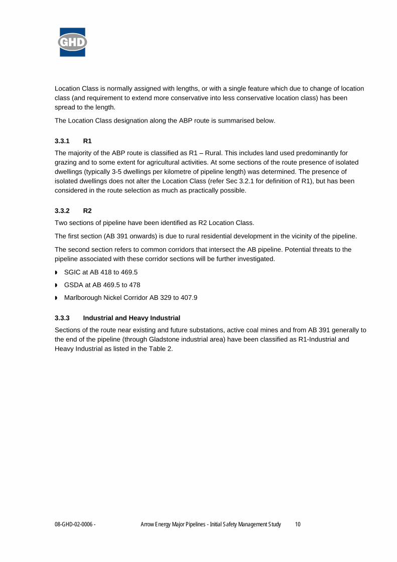
Location Class is normally assigned with lengths, or with a single feature which due to change of location
class (and requirement to extend more conservative into less conservative location class) has been
spread to the length.
The Location Class designation along the ABP route is summarised below.
3.3.1 R1
The majority of the ABP route is classified as R1 – Rural. This includes land used predominantly for
grazing and to some extent for agricultural activities. At some sections of the route presence of isolated
dwellings (typically 3-5 dwellings per kilometre of pipeline length) was determined. The presence of
isolated dwellings does not alter the Location Class (refer Sec 3.2.1 for definition of R1), but has been
considered in the route selection as much as practically possible.
3.3.2 R2
Two sections of pipeline have been identified as R2 Location Class.
The first section (AB 391 onwards) is due to rural residential development in the vicinity of the pipeline.
The second section refers to common corridors that intersect the AB pipeline. Potential threats to the
pipeline associated with these corridor sections will be further investigated.
SGIC at AB 418 to 469.5
GSDA at AB 469.5 to 478
Marlborough Nickel Corridor AB 329 to 407.9
3.3.3 Industrial and Heavy Industrial
Sections of the route near existing and future substations, active coal mines and from AB 391 generally to
the end of the pipeline (through Gladstone industrial area) have been classified as R1-Industrial and
Heavy Industrial as listed in the Table 2.
08-GHD-02-0006 - Arrow Energy Major Pipelines - Initial Safety Management Study 11
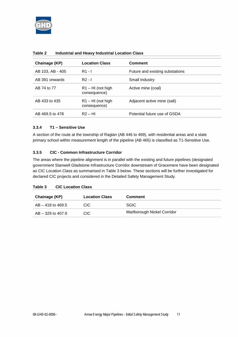
Table 2 Industrial and Heavy Industrial Location Class
Chainage (KP) Location Class Comment
AB 103, AB - 405 R1 - I Future and existing substations
AB 391 onwards R2 - I Small Industry
AB 74 to 77 R1 – HI (not high consequence)
Active mine (coal)
AB 433 to 435 R1 – HI (not high consequence)
Adjacent active mine (salt)
AB 469.5 to 478 R2 – HI Potential future use of GSDA
3.3.4 T1 – Sensitive Use
A section of the route at the township of Raglan (AB 446 to 469), with residential areas and a state
primary school within measurement length of the pipeline (AB 465) is classified as T1-Sensitive Use.
3.3.5 CIC - Common Infrastructure Corridor
The areas where the pipeline alignment is in parallel with the existing and future pipelines (designated
government Stanwell Gladstone Infrastructure Corridor downstream of Gracemere have been designated
as CIC Location Class as summarised in Table 3 below. These sections will be further investigated for
declared CIC projects and considered in the Detailed Safety Management Study.
Table 3 CIC Location Class
Chainage (KP) Location Class Comment
AB – 418 to 469.5 CIC SGIC
AB – 329 to 407.9 CIC Marlborough Nickel Corridor

08-GHD-02-0006 - Arrow Energy Major Pipelines - Initial Safety Management Study 12
Figure 1 - Locations Classes - Visual Guide
Primary Location Class
R1 R2 T1
Secondary Location Class
WCIC I HI S (Note)KP 0
74‐77
101‐102
103
329‐ 407.9
391
405
418 ‐ 4
69.5
433‐445
446‐469
465
478
Heavy In
dustria
l (activ
e coal m
ine) ‐ R1
/HI
Sensitive (p
ropo
sed mining camp) ‐ R1
/S
Indu
stria
l (substatio
n) ‐ R1
/I
Marlborou
gh Nickel Corrid
or ‐ R1
/CIC
Rural R
esiden
tial/Indu
stria
l ‐ R2/I
Indu
stria
l (substatio
n) ‐ R1
/I
SGIC ‐ ‐ R
1/CIC
Heavy In
dustria
l (activ
e salt mine) ‐ R1
/HI
Reside
ntial (Yarw
un) ‐ R1
Sensitive (schoo
l) ‐ T
1/S
End of ABP
Pipeline
Note: The ability to define S (and other location classes) at the ISMS stage depends on the available land use / GIS data collected by the Project.

08-GHD-02-0006 - Arrow Energy Major Pipelines - Initial Safety Management Study 13
4. Risk Identification
4.1 Penetration Resistance
Pipe wall thickness provides a resistance to penetration from an external interference threat. The level of
pipeline protection by resistance to penetration depends on the pipe wall thickness, material strength and
the physical parameters of the external interference threat.
Based on the input from the field it was determined that the maximum size of excavator that presents a
realistic threat from excavation for non-pipeline projects or work under control of third parties is a
35 tonne excavator. The “non-pipeline projects or work under control of third parties” refers to excavation
activities on the farms such as watering dam excavation, installation of drains or buried water PE lines,
installation of other services by third parties, and similar. Refer to Section 5.3 for further details about
possible use of other excavators or other external interference threats.
Penetration resistance calculations have been carried out to assess penetration resistance for the DN800
pipeline (current design case), and are provided in the attached wall thickness calculation report
(Appendix E).
4.2 No Rupture
The measurement length defines an area around the pipeline that is to be assessed for consequences of
loss of pipeline containment, whether from a “leak” or a “rupture”. The general land use, the presence of
residential areas, sensitive locations (schools, day care centres, hospitals, prisons, aged care facilities
and similar) are determined and the appropriate location class assigned.
The pipeline within a High Consequence Area (T1, T2, I and S location classes) must be designed for ‘no
rupture’ so that a rupture is not a credible failure mode. ‘Rupture’ in this context refers to a full-diameter
breach of the pipeline, or a ductile fracture, arrested within the initiating pipe that results in two open pipe
ends releasing gas. ‘No rupture’ compliance as per AS 2885.1 requirements is achieved by either:
1. Applying extra heavy wall pipe, so that the hoop stress does not exceed 30% of SMYS, or;
2. Determining the hoop stress such that that the “critical defect length” is less than 150% of the largest
equivalent defect length identified in that location.
It needs to be verified whether the 35 tonne excavator is the largest credible threat overall, specifically in
the high consequence areas. This will be done in the process of further design and in the process of
conducting the detailed safety management study.
4.3 Energy Discharge Rate
In addition to the no rupture requirements, AS 2885.1 sets maximum allowable energy discharge rates.
These rates must not exceed 10 GJ/s in Residential (T1), and Industrial locations (I), or 1 GJ/s in High
Density (T2) and Sensitive (S) Locations.
Energy discharge rates have been calculated and are listed in Table 4.

08-GHD-02-0006 - Arrow Energy Major Pipelines - Initial Safety Management Study 14
Table 4 Energy Discharge Rates
Energy Discharge (GJ/s) DN 800 and DN 1050 Pipeline Case (10.2 MPa)
1 46 mm hole
10 144 mm hole
Refer to the attached wall thickness calculation report (Appendix E) for a complete summary of the
resistance to penetration calculation.
In order to confirm whether the energy discharge criteria are met for the T1, I and S Location Class, the
threats that could create a hole in the pipe bigger than specified in Table 4 needs to be further
investigated and the resulting risks need to be thoroughly evaluated in a Detailed SMS.
4.4 High Consequence Areas
“High consequence” areas are locations where pipeline failure can be expected to result in multiple
fatalities or major environmental damage. For ABP, all the areas designated as T1 (residential), I
(industrial), and S (sensitive) are high consequence areas.
The route changes in the future are possible, and more detailed investigation during the design process
will confirm the presence of features such as nursing homes, schools, day care centres and similar which
may convert some areas into S location class.
The protection measures assigned to all high consequence areas are increased depth of cover
(1,200 mm) and heavy wall pipe.
4.5 Environmental and Land Constraints
The areas of environmental and land constraint have been investigated and mapped within the GIS. No
major environmental or land constraints have been determined during the Initial SMS, as apparently the
areas of concern have been avoided by careful route planning.

08-GHD-02-0006 - Arrow Energy Major Pipelines - Initial Safety Management Study 15
5. Threat Analysis and Safety Management Study
A comprehensive list of threats has been produced through the Initial SMS taking into consideration
previous experience and through the location analysis, using all available data and input from those who
have been investigating the proposed pipeline route in the field.
These threats will ultimately be associated with each and every location, as determined in the location
analysis. The Detailed SMS will then determine whether there are sufficient physical and procedural
measures in place to eliminate the threat, depending on the location class.
The typical overlay and location-specific threats have been identified in the course of location analysis as
shown in the SMS Location and Threat Analysis Table attached in Appendix D.
Overlay threats apply uniformly along the pipeline, whilst location specific threats are related to a point
location or a section (“length”) of the pipeline.
The threats can be also distinguished as either “design” or “external interference” events. The term
“design” should be interpreted very generally to mean all non-interference events (including operations). It
should not apply only to those items related to the engineers’ design.
The external interference events present the greatest danger to the pipeline, as statistically most pipeline
failures are as a direct result of external interference.
Furthermore, preliminary protection measures have been assigned in order to reduce all identified risks to
an acceptable level. This is the first step in the formal SMS. In the course of detailed design, this process
needs to be taken to the further level, which includes the detailed identification of threats, evaluation of
consequence and likelihood of pipeline failure, and formal ranking of risk and effectiveness of proposed
protection measures.
5.1 Overlay Threats
Listed below are some typical overlay or general threats from the complete listing:
Corrosion - external and internal;
Stress corrosion cracking;
Inadequate or incomplete maintenance;
Inadequate testing and inspection;
Undetected damage to pipe, coating or equipment;
Undetected critical weld defects;
Excavation of an existing pipeline or other service for maintenance or installation;
Terrorism, sabotage and vandalism; and
Fencing.

08-GHD-02-0006 - Arrow Energy Major Pipelines - Initial Safety Management Study 16
5.2 Location Specific Threats
Listed below are some typical location specific threats, from the complete listing:
Excessive external traffic loads;
Construction of other pipelines in Stanwell Gladstone Infrastructure Corridor;
Floods – erosion of cover;
Floods – floatation;
Pipeline scouring;
Table drain and road grading, and road maintenance;
Excavation of existing pipeline by third party;
Induced voltages from parallel power lines;
Quarry blasting;
Mining land subsidence;
Train derailment; and
Earthquake.
5.3 External Interference
External interference represents the most serious threat to most pipelines. Examples of external
interference threats include:
Blade ploughing;
Table drain and road grading, road maintenance;
Excavation by third party for farming activities;
Installation of third party services;
Road construction; and
Contour drain forming using bulldozers or graders.

08-GHD-02-0006 - Arrow Energy Major Pipelines - Initial Safety Management Study 17
6. Proposed Pipeline Risk Strategy
This section outlines the current risk mitigation strategies that are proposed for the threats that have been
identified as a result of the Initial SMS. The measures indicated are proposed to reduce the risk of the
listed threats occurring to an acceptable level.
For the purpose of this Initial SMS the threats and the proposed protection measures are previewed and
summarised only in the following section.
6.1 Overlay Threats
6.1.1 Excavation of an Existing Pipeline by Third Party
Excavation around the pipeline by third party for non-pipeline projects, or work under control of third
parties, refers to excavation activities on the farms such as watering dam excavation, excavation for new
drains, existing drains maintenance, installation of buried water PE lines; or it refers to other third party
work such as installation of other utility services by third parties, maintenance of existing utility services
and similar.
Excavation presents a threat by puncturing the pipeline with an excavator bucket. The maximum credible
size of the machinery used by a third party has been identified as a 35 tonne excavator fitted with
penetration teeth. More destructive plant such as excavators greater than 55 tonnes (normally used in
mines) is considered to be significantly rarer if not unlikely threats for these types of works.
The 35 tonne excavator fitted with penetration teeth would not penetrate either heavy or standard wall
pipe.
The pipeline will be monitored for third party work occurring along the right of way on a regular basis.
Pipeline marker signs will be installed at inter-visible intervals to indicate that there is a buried gas
pipeline. The signs will also show the operator’s phone numbers so that contractors etc. can ring prior to
commencing work or in case of an emergency. The stakeholders along the pipeline will be contacted
regularly and will be supplied with maps to ensure that they have the necessary information at hand to
identify the location of the pipeline.
Where the pipeline crosses third party services, the pipeline will generally pass under the other service,
Marker tape and marker mesh will be installed across the pipeline to provide an indication for gas
pipeline, and installation of concrete slab installed above the pipeline to provide a physical barrier will be
considered.
6.1.2 Corrosion – Internal
The gas entering the pipeline will be dehydrated to the transmission gas specification requirements,
which will ensure that free water will not enter the pipeline. The current gas composition has no
components which could initiate internal corrosion without water.
6.1.3 Corrosion – External
The pipeline will be coated with a high integrity protective coating as its primary protection from external
corrosion. This protective coating will be reinforced by a cathodic protection (CP) system, using an

08-GHD-02-0006 - Arrow Energy Major Pipelines - Initial Safety Management Study 18
impressed current or sacrificial anode system. The CP system will be monitored as part of the pipeline
management system to ensure that the correct negative potential is maintained along the pipeline.
CP test points will be located at critical crossings, and at regular intervals to assist with monitoring
performance.
6.1.4 Incorrect Construction, Testing and Inspection
The pipeline will be tested and constructed in accordance with AS 2885.1. The pipeline may be
constructed in an alliance or similar contractual arrangement to ensure that a balance between cost and
quality imperatives is maintained. The pipeline will be constructed from API 5L line pipe and therefore will
undergo extensive non-destructive testing. The pipeline will be constructed in accordance with a total
quality control plan including Non Destructive Testing (NDT), welding and holiday detection of the coating.
After installation, the pipeline will be hydrostatically tested in accordance with AS 2885.5.
6.1.5 Inadequate or Incomplete Maintenance
The pipeline will be maintained in accordance with AS 2885.3. This involves using a pipeline integrity
management plan and a Safety and Operating Plan. Pipeline operations will follow the requirements of
these plans, including scheduled maintenance and pipeline integrity checks, such as coating surveys and
intelligent pig runs. The pipeline and facilities will be operated by experienced and competent operators
who are familiar with the operation and the maintenance of the equipment being used.
6.1.6 Terrorism
In the light of the current political climate globally and in Australia, the possibility of a terrorist act cannot
be dismissed. A terrorist act on a pipeline may occur in a rural area if the objective is to interrupt supply,
and to escape apprehension. It is presumably less likely that an attack would occur in a heavily populated
area, since detection is more likely. Another factor is that it takes time to expose and damage a buried
pipeline, and presumably terrorists would have little time (before detection) if working in a populated area.
Pipeline stations present a potential target as the high-pressure gas equipment is above-ground, albeit
protected by a fenced compound. Again, it is considered more likely that such a site would be attacked
when it is unattended. The mitigation measures will be the restriction of access to pipeline stations and
facilities by security fencing and intruder alarms and by patrolling the pipeline.
6.1.7 Sabotage, Vandalism and Malicious Damage
As the pipeline is buried along its entire route and is fairly remote, the likelihood of potential deliberate
sabotage is reduced. The main areas of higher risk are the pipeline stations. Compared with terrorism,
vandalism is anticipated to have lesser consequences, although frequency would be higher. Locations
chosen for the above ground facilities will consider visibility and access. The metering stations are likely
to be fitted with intruder alarms to indicate unauthorised access.
6.1.8 Stress Corrosion Cracking (SCC)
SCC occurs generally downstream of compressor stations, where the pipeline is subjected to a high
stress range and high temperature. The risk of SCC occurring on the pipeline will be comprehensively
evaluated and specific measures may need to be implemented. These may include specific joint coatings,
sections of heavy wall pipe, or a more extensive coating inspection and maintenance program.

08-GHD-02-0006 - Arrow Energy Major Pipelines - Initial Safety Management Study 19
6.1.9 Earthquake
Operating experience has shown that buried gas pipelines are particularly resistant to earthquake forces.
The route will be reviewed to determine areas of especially high acceleration coefficient, and intersection
with faults (as per AS 1170). Where faults are encountered, correlation will be sought with recent seismic
activity to determine whether the fault should be classified as active.
Where positively active faults are intersected, precautions such as heavy wall pipe or above-ground
roller-supported pipe will be considered.
6.2 Location Specific Threats
6.2.1 Mining Land Subsidence
Areas subject to ground movement are primarily the areas in the mining leases, in particular where long
wall mining and underground coal gasification (UCG) is anticipated. These areas have been avoided by
pipeline route selection where it was feasible; however the pipeline traverses mining leases at some
locations (AB 74 to 77, EL 3 to 6, DL 7.3 to 14.1, SL 3.1 to 6.7). The likely extent and magnitude of land
subsidence needs to be established by liaising with the miner, in order to either avoid the land subsidence
areas by further route adjustments or assess what design options could be implemented to accommodate
for subsidence of certain magnitude.
6.2.2 Construction of Other Pipelines in Gladstone State Development Area
It is very likely that at least one other large diameter high pressure gas pipeline will have been installed in
government Gladstone State Development Area (GSDA) near Gladstone, parallel to the ABP. Given the
diameters of these pipelines, the size of the excavating machinery for maintenance of this type of works
could well be in the order of 80 or 90 tonne. The data for this type of the machinery needs to be gathered
and assessed for penetration resistance as they are not specified in AS 2885.1. However it has been
assessed that in this case it can be relied to a significant extent on procedural methods, such as site
supervision and work permit system, for the protection of the pipeline. This is because the construction of
the other pipelines is anticipated to be happening in the time period before the ABP is installed, therefore
there will be general awareness of both the ABP installation and of other projects (due to their size), and
accurate GIS data on the ABP location will be available.
6.2.3 Blade Ploughing
The location analysis indicates that blade ploughing is likely to occur in multiple long sections of the
pipeline route. Blade ploughing is a land clearing activity carried out periodically to control the regrowth of
native vegetation, generally to a depth that does not exceed 300-400 mm. However, the blade plough can
penetrate deeper at some locations because of uneven terrain, localised washouts, melon holes etc.
In areas that may be subject to blade ploughing, now or in the future, the pipeline is proposed to be
buried with a cover of 1,200 mm. In order to confirm the realistic depth of cover that would provide
adequate protection against blade ploughing, the threat of blade ploughing needs to be further
investigated to more accurately determine what is the maximum depth that a blade plough could
penetrate.

08-GHD-02-0006 - Arrow Energy Major Pipelines - Initial Safety Management Study 20
6.2.4 Contour Forming
Land contour forming for agricultural purposes has been identified in some areas. At quite a few locations
along the route this threat is considered as co-existent with blade ploughing.
Contour forming is normally carried out by a bulldozer and grader, to a depth on occasions beyond
700 mm. The areas where contour forming is regarded as possible have been initially identified, and need
to be further confirmed through site surveys, landowner liaison or other methods. The proposed
protection measure is an increased depth of cover of 1,200 mm, to ensure that it is not affected by
contour forming or maintenance. Further investigation of the contour forming threat is required in order to
confirm the realistic depth of cover that would provide adequate protection.
6.2.5 Induced Voltages
The location analysis has identified several areas where the pipeline alignment is parallel with high
voltage power lines for some distances, for example at AB 81 to 85.6, AB 462.9 to 464 and EL 47 to 48.5.
Where this occurs, a study will be performed to calculate the effect of the induced voltage and the fault
current on the pipeline during detailed design. Design measures will be implemented, as required, to
ensure continued pipeline integrity and operator safety.
The pipeline has been located, as far as practicable, to avoid parallel railway lines, and therefore to avoid
potentially serious induced voltages and fault currents. If proximity is unavoidable, suitable mitigation
such as installation of monolithic insulation joints, and other measures will be employed to ensure the
continued integrity of the pipeline and its cathodic protection system.
6.2.6 Failure of Control and Protective Equipment
The design intention is for pipeline and station pressure control systems to be high integrity, with full
redundancy. The pipeline may be protected from high temperature by a shutdown system.
The design philosophy at the meter station will incorporate dual regulator runs to minimise the possibility
of supply interruption from a single component failure.

08-GHD-02-0006 - Arrow Energy Major Pipelines - Initial Safety Management Study 21
6.2.7 Excessive External Traffic Loads
Several types of road crossing were identified in the location analysis. These are:
Formed gravel,
Unformed dirt,
Bitumen,
Paper roads (road casements without a gazetted road), and
Landholders’ access tracks.
These crossings will be designed with additional cover, heavy wall pipe and concrete slabs within table
drains, as per the standard crossing design.
To ensure that the pipelines cannot be overloaded in these locations, the depth of cover will be checked
as specified in AS 2885.1, i.e. in accordance with the requirements of API Recommended Practice 1102
“Steel Pipelines Crossings - Rail, Roads and Highways”. The loads used in the calculations will be the
maximum allowable axle loadings in accordance with the requirements of the Department of Main Roads.
6.2.8 Floods - Erosion of Cover
Erosion of cover is also possible at creek and river crossings, especially on the banks. For the majority of
the creek and river crossings, increased depth of cover of 1,200 mm and 2,000 mm respectively will be
used and protection measures installed on the banks as required by the crossing design.
6.2.9 Floods – Floatation
The low lying areas identified in the location analysis as prone to flooding may require buoyancy control
measures. These measures would include extra depth (1,200 mm), concrete coating of the pipeline, set-
on weights, or other buoyancy control measures to ensure that the pipe is negatively buoyant.
Flood areas will be determined in the further investigation and considered in the design.
6.2.10 Pipeline Scouring
The location analysis does not identify specific locations currently susceptible to scouring, however where
these areas are identified during design and construction, trench breakers will be installed to prevent
tunnelling of water and contour banks will be used to divert flows away from the pipeline onto undisturbed
areas.
6.2.11 Train Derailments
Sections of the route where the pipeline runs parallel with or crosses, a rail line will be installed generally
with additional depth of cover, using heavy wall pipe. Rail crossings will be carried out by thrust boring or
horizontal directional drilling and will be at an increased depth of cover as specified in AS 2885.1 i.e. in
accordance with the requirements of API Recommended Practice 1102 “Steel Pipelines Crossings – Rail,
Roads and Highways”. The proposed design is a minimum depth of cover of 2,000 mm under the table
drain, which will prevent possible contact during a derailment.

08-GHD-02-0006 - Arrow Energy Major Pipelines - Initial Safety Management Study 22
6.2.12 Table-Drains, Road Grading, and Road Maintenance
As mentioned above, standard construction methods are to be used across roads. These standard
construction details include concrete slabs under the table drains to prevent accidental over-excavation
above the pipeline. The pipeline is also buried with additional cover, and pipeline marker tape is installed,
across the road reserve.
6.2.13 Quarry Blasting
The pipeline passes close to some currently operating quarries. Blasting studies and calculations, for
some recently completed pipelines, indicated that separations as small as 50 m between explosive
charges up to 200 kg, and pipelines, are adequate to ensure that the pipeline is not damaged. It is
therefore considered likely that the pipeline route will be able to be easily adjusted to bypass quarry areas
and maintain the necessary separation. This will be reviewed during detailed design.

08-GHD-02-0006 - Arrow Energy Major Pipelines - Initial Safety Management Study 23
7. Actions
During the course of the Initial SMS, actions were identified to either confirm conditions along the route,
investigate risk elimination by realignment of the route, confirm the presence of sensitive areas or nearby
facilities, and further investigate the likely consequence of some external interference threats.
This will be done in preparation for the Detailed SMS, in order to confirm the designated Location Class,
determine threats to a further level of certainty and detail, propose required protection and mitigate risks
to the lowest practical level. The outstanding actions that need to be addressed are listed in Table 5 and
Table 6.
Table 5 Actions from Workshop
Chainage (KP) Threat Description Action Close Out
Powerline crossings
AB 70.1, 76.9, 77.9, 81 to 85.6, 253.5, 303.8, 354.6, 462.9 to 464
EL 13, 47.7, 47.8 to 48.5
Fault to earth - electrocution
Check radius of effect of earth faults - does it affect the pipeline.
Active mine (coal)
AB 74 to 77,
EL 3 to 6
SL 3.1 to 6.7
DL 7.3 to 14.1
Vibrations from blasting
Check with the coal mining companies with respect to potential blasting.
SGIC at AB 418 to 469.5
GSDA at AB 469.5 to 478
Marlborough Nickel Corridor AB – 329 to 407.9
Check declared CIC projects with interests.
Typical parallel water pipeline
AB 90 to 93
Vehicle loads during maintenance activities
Make sure the fence is specified in the licence agreement.
*Cleared areas - purpose unknown
AB 0 to 478 (all), EL 37 to end of lateral
Blade ploughing Review previous study by GHD on depth of blade ploughing to see whether 1,200 mm is enough.
Possible cultivation
AB 159 onwards, AB 172 to 174, AB 211 onwards, DL 0 onwards
Blade ploughing Review previous study by GHD on depth of blade ploughing to see whether 1,200 mm is enough.

08-GHD-02-0006 - Arrow Energy Major Pipelines - Initial Safety Management Study 24
Chainage (KP) Threat Description Action Close Out
Centre pivot irrigation to grow vegetation
AB 244 to 245
TBC Determine method and depth of tillage for centre pivot irrigation.
Contour banks (may be extended)
AB 311, AB 318 to 319, AB 343 to 344, AB 358 to 359, AB 372 to 373
Damage to pipe Determine the depth required for contour banks.
Possible flood plains
AB 320 onwards, AB 428 onwards, EL 29
Inundation with simultaneous liquefaction
Carry out appropriate geotech study.
Entire length Material Defects Require contractor to demonstrate
minimised and careful handling of coated pipe.
Entire length
Hydrotesting issues and 0.8 design factor issues
Make sure pipe spec captures recent industry lessons learned on items such as stress-strain curves, coating process, strain ageing, yield ratio, field weldability (all tests done on coated pipe).
Consider the initial additional impact of spiral welded pipe.
Entire length Coating damage in general
Ensure spec prescribes the use of brush type jeeper.
Entire length Undiagnosed welding defects due to poor NDT
Baseline calibration of AUT.
Entire length Cyclic fatigue of pipeline due to operation of upstream gathering system and downstream LNG plant
Confirm that cyclic operation does not give rise to fatigue design on the pipeline.
*Note: Identified cleared areas with the ‘purpose unknown’ differ from identified areas where cultivated land was evident.

08-GHD-02-0006 - Arrow Energy Major Pipelines - Initial Safety Management Study 25
Table 6 General Actions
Item # Action Assigned To
1 Railway depth of cover - measured from bottom of ballast? GHD
2 Specify minor and major watercourse crossings in the pipeline walk through GHD
3 Investigate possible third party CSG well at AB 89. Arrow
4
Investigate land use in area at AB 95 to 97, AB 98 to 100, AB 107, AB 133 to 137, AB 244 to 245 and check whether cleared area will be expanded with land owner. Arrow
5 Determine type of pipeline in easement at AB 96.8 approx. Arrow
6 Investigate the type of mining and mining methods at AB 227 to 228. Arrow
7 Investigate potential contour banks at AB 299 to 300, AB 319. Arrow
8 Investigate possible easement at AB 303.5. Arrow
9 Investigate cadastral portion at AB 364. Arrow
10 Investigate nature of structure/dwelling at AB 371.5. Arrow
11 Investigate nature of dwelling at SW of AB 373. Arrow
12 Check with local council the zoning at AB 380 to ensure that density does not increase further. Arrow
13 At AB 383 dwelling within 100 m of centreline, investigate moving the dwelling or the pipeline route. Arrow
14 Investigate structure/ruin at AB 386.5 Arrow
15 Investigate at NE of AB 397 looped track, is this a commercial enterprise. Arrow
16 Investigate AB 410.7 possible quarry. Is future quarry intended? Arrow
17 At AB 433 determine possible future extensions to salt mining. Arrow
18 At AB 446.3 waste transfer station needs to be relocated. Pipeline cannot be relocated due to SGIC. Arrow
19 Check at AB 445.5 to 446.5 (the reserve) what land use approvals are required for this apparent break in the SGIC. Arrow
20 Investigate at SW AB 446. Are these ponds/sewerage plants or what? Arrow
21 Investigate at AB 454 - 455 the number of houses/occupants in this town/village. Arrow
22 Calculate the overlap of measurement lengths in T1 and sensitive location class zones. GHD

08-GHD-02-0006 - Arrow Energy Major Pipelines - Initial Safety Management Study 26
Item # Action Assigned To
23 Investigate the feasibility of medium/heavy vessel making it up major rivers far enough to damage pipeline. Arrow
24 Investigate operating pressures for slurry pipelines to further consider threats posed to adjacent gas pipelines. GHD
25 GHD to determine frequency of DCVG surveys for detecting latent defects from third party impact. GHD
26 Determine the probability of blasting. Arrow
27 Try to find photo of lightning strike - Brian Martin, EPRA papers. GHD
28 Send sketch showing current MLV locations to GHD. Arrow
29 Ground truth between EL 8-9. Arrow
30 Confirm existence of well at EL 30 and evaluate if too close to the pipeline. Arrow
31 At EL 46 realign pipeline slightly to avoid mining township (if required once measurement length of EL is confirmed). Arrow
32 Check the proximity of wellheads at DL 3, 3.5, 6.7. Arrow

08-GHD-02-0006 - Arrow Energy Major Pipelines - Initial Safety Management Study 27
8. Conclusions
The scope of the Initial SMS for ABP was as follows:
Identification of basic pipeline design parameters.
Location analysis, including definition of “high consequence” areas.
Identification of typical overlay general threats.
Identification of main location specific threats.
Preliminary proposed risk strategy to reduce all identified risks to ALARP.
The scope has generally been fulfilled and the results of the Initial SMS workshop summarised in the
SMS Location and Threat Analysis Table in Appendix D.
In the course of the Initial SMS, a significant number of issues were identified that require further
investigation or action. These can be summarised as follows:
Confirmation of conditions along the route;
Investigation of extent of flooding areas;
Confirmation of presence and extent of sensitive areas; and
Further investigation of some major external interference threats in order to determine optimum
protection measures.
These actions are noted in the SMS Location and Threat Analysis Table and the separate comprehensive
list of actions has been presented for clarity in Section 7 of this Report.
The pipeline route that was assessed in the course of the Initial SMS is referred to as Revision D. The
indicative map of the route is provided in Appendix A. Any changes in the route that may occur after the
Initial SMS workshop will need to be evaluated. The SMS process will therefore be continued through
further design and formalised by conducting a detailed SMS.
The detailed SMS shall determine the exact physical and procedural measures required to mitigate
threats, assess whether these measures eliminate the threat, assign consequence and likelihood values
to non-eliminated threats, determine the risk ranking and assign appropriate risk treatment actions.

08-GHD-02-0006 - Arrow Energy Major Pipelines - Initial Safety Management Study 28
9. Disclaimer
This Report: has been prepared by GHD for Arrow Energy Pty Ltd and may only be used and relied on by Arrow Energy Pty Ltd for the purpose agreed between GHD and Arrow Energy Pty Ltd as set out in Section 1 of this Report.
GHD otherwise disclaims responsibility to any person other than Arrow Energy Pty Ltd arising in connection with this Report. GHD also excludes implied warranties and conditions, to the extent legally permissible.
The services undertaken by GHD in connection with preparing this Report were limited to those specifically detailed in the Report and are subject to the scope limitations set out in the Report.

08-GHD-02-0006 - Arrow Energy Major Pipelines - Initial Safety Management Study
Appendix A
ABP and ASP Pipelines Route Map (for Initial SMS – Alignment Rev D)


08-GHD-02-0006 - Arrow Energy Major Pipelines - Initial Safety Management Study
Appendix B
Assumptions for SMS and Conclusion of Preliminary Calcs

High level assumptions:
Stations and facilities not considered.
Construction not considered except for construction adjacent to operating pipeline.
Assumed homestead within measurement lengths are not treated as sensitive
Assumed all pipelines and laterals are piggable
Comments
Pipeline Nominal Diameter DN 800 (32 inch)
Pipe Material API 5L X70
Pipeline Length 478 km approx.
Pipeline Contents CSM
Rich Gas Composition(assumed)
Methane - 98.45%, Ethane (0.10%),Propane (0.10%), i-butane (0.10%), n-butane (0.10%), i-pentane (0.10%) , n-pentane (0.10%), Hexane (0.10%),Nitrogen (0.70%), Carbon Dioxide(0.15%) As per SGP Design Basis
Primary Location ClassesAlong Route R1Secondary Location ClassesAlong Route TBD
Design Factor0.8 Pipeline0.67 Facilities
Corrosion Allowance 0 mmExternal Threats / Plant in theRegion Refer to SMSIs "NO RUPTURE" DesignRequired ? Yes in high consequence areasCan rupture occur? If so, forwhat size plant?
No for up to 35T excavator, assumingheavy wall pipe used
Permissible Energy ReleaseRates in Each Location Class High Consequence - 10GJCalculated Energy ReleaseRate No LeakMeasurement Length(4.7kW/m2) (injury in 30 secsexposure) 1100 m approx.
Largest excavator sizeconsidered (design excavator) 35T
Worst case tooth Twin Tiger (one tooth)
Are the Nominated ExcavatorsCapable of Achieving "Leak"?
No - standard wallNo - heavy wall
Are there any "non-excavator"Threats/ Plant Capable ofAchieving Rupture ? Yes refer to SMS
Area/ Feature
R1 and R2 Areas
High Consequence Areas (exl.T2)
W Areas
Track - Open Cut
Crossing Cover 1500mm
Table Drain 1200mm
Concrete Slabs in Drain No
Crossing Cover 1500mm
Table Drain 1200mm
Concrete Slabs in Drain No
Crossing Cover 2000mm
Table Drain 2000mm
Concrete Slabs in Drain No
Legal Planned Road Reserve/Crossing
Water Course - Minor (<10mtoe to toe)
Crossing Cover 1200mm
Preliminary Depth of Cover SelectionsDOC (minimum)
1200mm (TBD)
Road - Bored
ABP Pipeline
Highway Crossing
1200mm
750mm
Assumptions for SMS and Conclusion of Preliminary Calcs
Road - Open Cut
TBD
1200mm

Water Course - Major Crossing Cover 2000mm
Crossing Cover 2000mm
Table Drain 2000mm
Foreign UtilityNormally cross below foreign utility, as
opposed to above.600mm
Foreign Utility - Above Ground
HV Power Line Crossing
Man Made Drain
Underneath Road 1500mm
Beside 1200mm
HV Power Line Parallel
Fibre Optic Parallel
Flood Plains
R1/R2 "Standard Wall (Note 1)High Consequence "Heavy Wall"
(Note 2)Road Crossing "Heavy Wall"
(Note 5)Rail Crossing "Heavy Wall"
(Note 3)Pipeline Assemblies
(Note 6)
10.7 mm 12.5 mm 13.8 mm 14.9 mm 12.8 mm
Notes1. Based on pressure containment with Fd = 0.8 Occasional vehicle crossings and other criteria not considered.2. Excludes design for S and T2 areas.3. Depending on quantities required, consider rationalising the high consequence road crossing and rail crossing heavy wall materials.4. Other wall thickness criteria, such as fatigue, have not been considered.5. For designated, not occasional crossings.6. Based on pressure containment with Fd = 0.67.
Hole size Area Energy release (GJ/s)10 78.53981634 0.04789494720 314.1592654 0.19157978830 706.8583471 0.43105452240 1256.637061 0.7663191550 1963.495408 1.19737367260 2827.433388 1.72421808870 3848.451001 2.34685239880 5026.548246 3.06527660190 6361.725124 3.879490698100 7853.981634 4.789494689110 9503.317777 5.795288573120 11309.73355 6.896872352130 13273.22896 8.094246024140 15393.804 9.38740959150 17671.45868 10.77636305160 20106.19298 12.2611064170 22698.00692 13.84163965180 25446.90049 15.51796279190 28352.8737 17.29007583200 31415.92654 19.15797876210 34636.05901 21.12167158220 38013.27111 23.18115429230 41547.56284 25.3364269240 45238.93421 27.58748941250 49087.38521 29.93434181260 53092.91585 32.3769841
0 1170 1
0 10170 10
Preliminary Wall Thickness Selections
As per surrounding area
As per surrounding area
1200mm
Railway
TBD
As per surrounding area
As per surrounding area
Parallel to Road
Combine? (Note 3)
Combine? (Note 3)
0
2
4
6
8
10
12
14
16
0 20 40 60 80 100 120 140 160 180
Ener
gy R
elea
se R
ate
(GJ/
s)
Hole Diameter (mm)
Energy Release Rate Vs. Hole Size10.2 MPa
Calculated Energy Release
1GJ/s
10GJ/s

08-GHD-02-0006 - Arrow Energy Major Pipelines - Initial Safety Management Study
Appendix C
Workshop Attendance Record


08-GHD-02-0006 - Arrow Energy Major Pipelines - Initial Safety Management Study
Appendix D
SMS Location and Threat Analysis Table

SMS Location and Threat Analysis Table
Severity Risk RankingDimensions Catastrophic Major Severe Minor Trivial Catastrophic Major Severe Minor Trivial
Initial SMS Workshop Record PeopleMultiple fatalities, or
Several fatalities or major injuries, orHospital treatment,or
First Aid Treatment, or "Minimal" Frequent Extreme Extreme High Intermediate Low
Project: Supplylong supplyinterruption, or restricted supply, or
Short interruption ofprolongedrestriction, or
Short supply restriction,or
No impact on supply Occasional Extreme High Intermediate Low Low
Date: Environment
ecosystem changedor made unviable
longtoterm environ impacts, hard to rectifyEnv Effects <1Haand <2yr, easilyrectified
Env impact <0.1Ha &few weeks
"Minimal" Unlikely High High Intermediate Low Negligible
Location: Remote High Intermediate Low Negligible Negligible
Facilitator: Hypothetical Intermediate Low Negligible Negligible Negligible
FrequencyOnce per year or more FrequentSeveral times in life of p/l
Occasional
Possible, but probablynot in life of this p/l
Unlikely
Not anticipated for thisp/l
Remote
Never occurred onsimilar p/l
Hypothetical
Pr= ProceduralPh= PhysicalR1and R2 require 1Ph + 2 PrT1 and T2 require 2 Ph + 2 Pr
Threat AnalysisFailure Analysis (referFracture Control Plan andEnvironmental & Other Plans
Risk TreatmentALARP Analysis
(if required)Actions
No.Point/Length Location
(Approx. KP)Primary
Location Class
SecondaryLocation Class(if applicable)
PredominantLand Use and
Other FeaturesCredible Threats
RequiredMeasures for
ExternalInterference
Threats
Selected Protection Measures
Failure ofProtectiveMeasuresPossible?
Comments / Actions from InitialSMS
Severity Frequency Risk Ranking
NEG: Review in FutureLOW: Management PlanINTER: Retoevaluate or ALARPanalysisHIGH Retoevaluate ASAPEXTREME: Retoevaluate
1.1 R1 Grazing Vehicle Loads 1Ph + 2 Pr No
Road maintenance activities i.e. excavations andgrading
Yes, for majorrework
Vehicle collision/Bogged vehicles (any vehicles) No
Erosion at track edges No
1.2 R1 Vehicle Loads 1Ph + 2 Pr No
Road construction activities i.e. excavations andgrading
Yes, for majorrework
Vehicle collision (any vehicles) No
Bogged vehicles (any vehicles) No
Erosion at track edges No
1.3 R1 Vehicle Loads 1Ph + 2 Pr No
Road maintenance activities i.e. excavations andgrading
No
Vehicle collision (any vehicles) No
Bogged vehicles (any vehicles) No
Erosion at track edges No
Road realignment Yes
Installation of large traffic signs/guard rails/lightposts
Yes
1.4 R1 Vehicle Loads No
Road maintenance activities i.e. excavations andgrading
No
Vehicle collision (any vehicles) Yes, due to sizeand weight ofvehicles
Bogged vehicles (any vehicles) No
Erosion at track edges No
Road realignment Yes
Installation of large traffic signs/guard rails/lightposts
Yes
1.5 R1 Flotation No
Vessel (small)/anchor/tree impact TBA
Large objects during flood impacting the pipeline Yes, large objectsand in combinationwith erosion ofcover
Erosion of cover Yes
1.6 R1 Flotation No
Erosion of cover Yes
Large objects during flood impacting the pipeline Yes, large objectsand in combinationwith erosion ofcover
Arrow Energy Offices,Bne
Location Analysis
Depth of cover (Ph)Signage (Pr)Wall thickness (Ph)Arrow inspector on site during activities (Pr)Third party liaison (Pr)Dial before you dig (Pr)
Depth of cover (Ph)Signage (Pr)Wall thickness (Ph)Arrow inspector on site during activities (Pr)Third party liaison (Pr)Dial before you dig (Pr)
Depth of cover (Ph)Signage (Pr)Wall thickness (Ph)Arrow inspector on site during activities (Pr)Third party liaison (Pr)Dial before you dig (Pr)
Depth of cover (Ph)Signage (Pr)Wall thickness (Ph)Arrow inspector on site during activities (Pr)Third party liaison (Pr)Dial before you dig (Pr)
Depth of cover (Ph)Heavy wall (Ph)CWC (Ph)
AB Gas Pipeline to Rev DAlignment
J Doyle
Risk AssessmentAS 4360 / 2885 App F
Thursday/Friday August25th/26th 2011
Note that the workshop was conducted in accordance with the Pipeline SafetyManagement Process of AS 2885.1 to 2007, as illustrated in the flowchart inFigure 2.3.1 of AS 2885.1. When reviewing this workshop record it should beread in conjunction with the flowchart.
Protection Analysis
1. Location Specific Threats
Depth of cover (Ph)
Typical Track CrossingAB 0 to 478 (All)All laterals
Future Road crossingsAB 0 to 478 (All)All laterals
Typical Road CrossingAB 0 to 478 (All)All laterals
Typical Highway CrossingAB 95, 404.9, 416.4
Typical watercourse majorcrossings i.e. riversAB 0 to 478 (All)All laterals
Typical watercourse minorcrossings i.e. creeks, drains,streamsAB 0 to 478 (All)All laterals
1

SMS Location and Threat Analysis Table
1.7 R1 Train Loads No
Train derailment to impact on pipeline Yes
Rail maintenance activities i.e. sleeperreplacement, track relays
No
Induced voltage from train line No
1.8 R1 Power Lines InProximity
Fault to earth to electrocution No Check radius of effect of earth faults todoes it affect the pipeline.
Fault to earth to coating damage Yes
Power pole installation Yes
1.9 R1 Pipeline maintenance activities i.e. excavation Yes
Vehicle loads during maintenance activities Yes
Installation of other pipelines Yes
Catastrophic failure of third party pipeline due toCP conflict
Yes
Catastrophic failure of third party pipeline due toany cause
Yes
1.10 R1 Pipeline maintenance activities i.e. excavation Yes
Vehicle loads during maintenance activities Yes
Water leak causing loss of cover Yes
1.11 R1 Other Pipeline inVicinity
Vehicle loads during maintenance activities Yes
Water leak causing some loss of cover Yes
1.12 R1 Petroleum Lease Wells (assumed Arrow wells):Drilling
Yes
Vehicle loads/bogging Yes
Flow lines (assumed Arrow flow lines)Trenching Yes
Vehicle loads Yes
Dam (assumed Arrow Dam)Bulk excavation/scrapers/dozers Yes
Vehicle loads Yes
1.13 R1 Petroleum Lease Wells (third party)Drilling
Yes
Vehicle loads/bogging Yes
Flow lines (third party)Trenching Yes
Vehicle loads Yes
Dam (third party)Bulk excavation/scrapers/dozers Yes
Vehicle loads Yes
1.14 R1 Mining Lease Possible open cut mining to physical impact ofpipeline
No
Possible underground mining to subsidence Yes
Vibrations from blasting Yes Look for overlaps between undergroundmining and large water course crossingsof pipelines.
Mine trucks traversing pipeline No
1.15 R1 Mining Lease Tracked vehicles adjacent to the pipeline or accesstrack construction
Yes
1.16 R2 CIC Industrial
1.17 R1 Pipeline maintenance activities i.e. excavation No
Vehicle loads during maintenance activities No
Catastrophic failure of third party pipeline due toany cause
No
1.18 R1 Vehicle loads during maintenance activities Yes Make sure the fence is specified in thelicence agreement.
Water leak causing loss of cover Yes
Check declared CIC projects withinterests.
Signage (Pr)Marker Tape (Pr)Separation (Ph)Proposed light duty fence between water andgas pipelines during construction (Pr)Third party liaison (Pr)Dial before you dig (Pr)Accurate positioning of pipeline (Pr)
Heavy Industrial(not high
consequence (nocoal stock piles and
mine does notdirectly lay over
pipeline))
Active mine (coal)AB 74 to 77
EL 3 to 6SL 3.1 to 6.7DL 7.3 to 14.1
Heavy Industrial(not high
consequence)
Signage (Pr)Marker Tape (Pr)Patrols (Pr)Community liaison (Pr)Liaison between proponent companies andexclusion of mining around pipeline preventswork within the pipeline easement (Pr)
Arrow inspector on site during activities (Pr)Depth of cover / Concrete slabs (Ph)Signage (Pr)Marker Tape (Pr)Separation approx. 30m (Ph)Depth of cover / separation / concrete slabs(Ph)Third party liaison (Pr)Dial before you dig (Pr)Accurate positioning of pipeline (Pr)
Typical parallel gas pipelineAB 265 to 349 (AGL),AB 329.2 to 407.5 (GladstoneNickel Project p/l),AB 408.7 to 411.1 (Gladstone torocky p/l (AGL Jemena to tbc))
Other Pipeline inVicinity
Wall thickness (Ph)Depth of cover (Ph)Signage (Pr)Arrow inspector on site during activities (Pr)Third party liaison (Pr)Dial before you dig (Pr)Correct pipeline earthing design (Ph)
Lateral separation (Ph)Operation safety procedures i.e. earth mats(Pr)Signage (Pr)Arrow inspector on site during activities (Pr)Third party liaison (Pr)Dial before you dig (Pr)Accurate positioning of pipeline (Pr)
Depth of cover / separation / concrete slabs(Ph)Signage (Pr)Marker Tape (Pr)Arrow inspector on site during activities (Pr)Third party liaison (Pr)Dial before you dig (Pr)Accurate positioning of pipeline (Pr)
Depth of cover / separation / concrete slabs(Ph)Signage (Pr)Marker Tape (Pr)Arrow inspector on site during activities (Pr)Third party liaison (Pr)Dial before you dig (Pr)Accurate positioning of pipeline (Pr)
Liaison between proponent companies andexclusion of mining around pipeline preventswork within the pipeline easement (Pr)
Assumed that pipeline is not designed for anysubsidence initially and capacity for subsidenceends up being calculated later
Signage (Pr)Marker Tape (Pr)
Signage (Pr)Arrow inspector on site during activities (Pr)Accurate positioning of pipeline (Pr)Patrols (Pr)
Signage (Pr)Arrow inspector on site during activities (Pr)Accurate positioning of pipeline (Pr)Patrols (Pr)
Typical Rail CrossingAB 90, 92.3, 101, 393, 416.5,427.6, 471EL 47
Powerline crossingsAB 70.1, 76.9, 77.9, 81 to 85.6,253.5, 303.8, 354.6, 462.9 to 464EL 13, 47.7, 47.8 to 48.5
Typical buried gas pipelinecrossingAB 0 to 478
Typical buried water/slurry pipelinecrossingAB 11.8EL 46.9
Other Pipeline inVicinity
Other Pipeline inVicinity
Typical above ground water/slurrypipeline crossingAB 387.2
CSG infrastructure Arrow: wells,flow lines, dam constructionAB 81.8, 89EL 30.2DL 2.2, 6
CSG infrastructure third party:wells, flow lines, dam constructionAB 81.8, 89EL 30.2DL 2.2, 6
Adjacent active mine (salt)AB 433 to 435
CICSGIC at AB 418 to 469.5GSDA at AB 469.5 to 478Marlborough Nickel Corridor AB329 to 407.9
Typical parallel water pipelineAB 90 to 93
Other Pipeline inVicinity
TBA
2

SMS Location and Threat Analysis Table
1.19 R1 Power Lines InProximity
Induced voltages from nearby power transmissionlines
No
Fault to earth to electrocution No
Fault to earth to coating damage Yes
Power pole installation Yes
1.20 R1 Industrial Industrial Blasting Yes
Bulk earth works Yes
Outlying earthing stakes Yes
Induced currents No
Fault to earth to electrocution No
Fault to earth to coating damage No
1.21 R1 Sensitive Mining Lease No identified threat to the pipeline N/A
1.22 R1 Grazing Blade ploughing No
Vehicle loads Yes
Rippers No
1.23 R1 Cropping Blade ploughing No Determine the depth of tillage.
Vehicle loads Yes
Rippers No
1.24 R1 TBC No Determine method of tillage for centrepivot irrigation.
Underground water pipe installation Yes
1.25 R1 Cropping TBC No Determine the height, and thereforedepth of cover, required for contourbanking.
1.26 R1 None Inundation with simultaneous liquefaction No Carry out appropriate geotech study.
1.27 R1 None Loss of FJC and corrosion to the pipeline No
1.28 R1 Grazing Installation of normal fence posts No
Installation of corner and strainer posts Yes
Stock damaging signs Yes
Dam construction Yes
1.29 R1 Grazing Vibration from Seismic Surveys Yes
1.30 R2 Industrial Residential/SmallIndustry
Swimming pools and dam construction No
1.30 T1 Residential Swimming pools and dam construction Signage (Pr)Patrols (Pr)Third party liaison (Pr)Arrow inspector (Pr)
No
1.31 T1 Sensitive Residential No identified threat N/A
2.1 Entire Length Design Errors No
Signage (Pr)Patrols (Pr)Third party liaison (Pr)Arrow inspector (Pr)
ResidentialYarwunAB 446 to 469
Rural residential/possible industrialAB 391 onwards
Signage (Pr)Patrols (Pr)Third party liaison (Pr)Arrow inspector (Pr)
Heavy wall (Ph)Depth of cover (Ph)Signage (Pr)Patrols (Pr)Marker tape (Pr)Third party liaison (Pr)Dial before you dig (Pr)Accurate positioning of pipeline (Pr)
Increase depth of cover (TBC)Signage (Pr)Patrols (Pr)Third party liaison (Pr)Arrow inspector during site work (Pr)Dial before you dig (Pr)Accurate positioning of pipeline (Pr)
Geotech study to define tenancy of flotation,with buoyancy control
Study to confirm that PASS actually is ASS andthen study to confirm that FJC will resist theacid
Contour banking (may beextended)AB 311, 318 to 319, 343 to 344,358 to 359, 372 to 373
Possible flood plainsAB 320 onwardsAB 428 onwardsEL 29
Review previous study by GHD ondepth of blade ploughing to see whether1200 mm is enough.
Signage (Pr)Patrols (Pr)Third party liaison (Pr)
Correct earthing design (Ph)Lateral separation (Ph)Operation safety procedures i.e. earth mats(Pr)Signage (Pr)Arrow inspector on site during activities (Pr)Third party liaison (Pr)Dial before you dig (Pr)Accurate positioning of pipeline (Pr)
Heavy wall (Ph)Depth of cover (Ph)Signage (Pr)Patrols (Pr)Marker tape (Pr)Third party liaison (Pr)Arrow inspector during site work (Pr)Dial before you dig (Pr)CP/earthing design (Ph)Accurate positioning of pipeline (Pr)Careful earthing design in the vicinity of thesubstation (Ph)
Heavy wall (Ph)Depth of cover (Ph)Signage (Pr)Patrols (Pr)Marker tape (Pr)Third party liaison (Pr)Arrow inspector during site work (Pr)Dial before you dig (Pr)Accurate positioning of pipeline (Pr)
Depth of cover 1200 mm (Ph)Signage (Pr)Patrols (Pr)Third party liaison (Pr)Arrow inspector during site work (Pr)Dial before you dig (Pr)Accurate positioning of pipeline (Pr)
Depth of cover 1200 mm (TBC) (Ph)Signage (Pr)Patrols (Pr)Third party liaison (Pr)Arrow inspector during site work (Pr)Dial before you dig (Pr)Accurate positioning of pipeline (Pr)
Cleared areas to purpose unknownAB 0 to 478 km (all)EL 37 onwards
2. Design and MaterialsDesign has been to approved standards andhas been checked. Approvals matrix to AS2885
Hydrotesting (partial measure)
Experienced personnel (RPEQ)
Second and third party verification of design.
CNPC and Shell will also overview and auditdesign
ISO 9001 accreditation
Depth of cover 1200 mm (TBC) (Ph)Signage (Pr)Patrols (Pr)Third party liaison (Pr)Arrow inspector during site work (Pr)Dial before you dig (Pr)Accurate positioning of pipeline (Pr)
PASS (potential acid sulphatessoil)AB 428 onwards
GrazingAB 0 to 478All Laterals
Third party seismic surveys
Sensitive (school)AB 465
Parallel powerlinesAB 81 to 85.6, 462.9 to 464EL 47.8 to 48.5
Future and existing substationsAB 103, AB 405
Proposed mining campAB 101 to 102
Centre pivot irrigation to growvegetationAB 244 to 245
Possible cultivationAB 159 onwards, 172 to 174, 211 -onwardsDL 0 onwards
3

SMS Location and Threat Analysis Table
2.2 Entire Length Material Defects
2.3 Entire Length Hydrotesting issues and 0.8 design factor issues
3.1 Entire Length Coating damage in general No Ensure spec prescribes the use ofbrush type jeeper.
Coating damage after pipe lowering due to backfill No
3.2 Entire Length Undiagnosed welding defects due to poor NDT No Baseline calibration of AUT.
3.3 Entire Length Cyclic fatigue of pipeline due to operation ofupstream gathering and downstream LNG plant
No Confirm that cyclic operation does notgive rise to fatigue design on thepipeline.
4.1 Entire Length Pipeline Internal Corrosion
4.2 Entire Length Pipeline External Corrosion
4.3 Entire Length Stress Corrosion Cracking / Environmentalcorrosion cracking
No
4.4 Entire Length Fatigue Cracking No
4.5 Entire Length Bacterial Corrosion No
4.7 Entire Length Cathodic Protection Shielding No
4.8 Entire Length Overpressure Control System Failure Multi redundant pressure control system as perAS 2885
No
4.9 Entire Length Inadequate servicing of valves No
4.10 Entire Length Inadequate servicing or obscuring of signage.
4.11 Entire Length Inadequate servicing of CPUs.
5.1 Entire Length Lapsed or incorrect CP testing No
5.2 Entire Length Overheating of coating system
5.3 Entire Length Incorrect as builts No
5.4 Entire Length Failure of third party liaison
5.5 Entire Length Procedures which place too much onus operatorshaving very high and very broad skill levels
No
No
Yes
No
No
3. Latent Construction Defects
4. Operation and Maintenance
5. Operating Errors
Materials have been selected to comply withdesign standards.
NDT, ITPs, material certificates and hydrotestsminimise the possibility of defects existing in thepipeline and facilities.
Owners team QA inspections at start of steelmaking process and throughout the wholecoating/delivery supply chain
Retain expert advisers
Real special precautions around handling ofFBE (handling specification)
The effect of coating process on the pipe
Receiving metallurgical advice (as a result ofthe effect of FBE coating on the pipe)
Appropriate specification
Enforcement of specification on site anddedicated backfill inspector
DCVG survey post burial and monitoring of theCP performance
Proposing a DCVG regime (operationsprocess)
Appropriate spec
Enforcement of spec
Hydrotesting
Assessed cyclic stressesHigh quality coatingIntelligent pigging
Cathodic protectionDCVG surveysProtective coatingIntelligent piggingBackfill specification and enforcementExternal coating spec and enforcementProper discovery of ASSField joint coating specs and enforcement
Make sure pipe spec captures recentindustry lessons learnt on items such asstresstostrain curves, coating process,strain aging, yield ratio, field weldability(all tests done on coated pipe).
Consider the initial additional impact ofspiral welded pipe.
No, subject toacceptance andimplementation ofrecommendations/actions
No, subject toacceptance andimplementation ofrecommendations/actions
Liaison with upstream and downstream at thedesign basis stage
Recording of number of pressure cycles(SCADA)
Intelligent pigging
Non corrosive and dry gasWater samplingRegular piggingOccasional intelligent piggingMoisture analyser
Require contractor to demonstrateminimised and careful handling ofcoated pipe.
Control of gas quality
Assessed cyclic stressesIntelligent pigging
Quality coating
Regular inspections to maintenance scheduleExperienced personnelHigh quality valves
Patrols.
Potential surveysCPU readingsMaintenance schedule
Competent operatorsAvailable trainingOperating proceduresLicensed operatorFail safe design
Spot dig ups on unpigged linesRoutine audits of operating practices andSCADA historyCompetent operatorsAvailable trainingOperating proceduresLicensed operatorFail safe design
QA proceduresAuditsCompetent operatorsAvailable trainingOperating proceduresLicensed operatorFail safe design
QA proceduresAuditsCompetent operatorsAvailable trainingOperating proceduresLicensed operator
Clear and unambiguous procedures andenforcementReview of operating procedures regularly
No
No
4

SMS Location and Threat Analysis Table
6.1 Entire Length Bushfire
6.2 Entire Length Lightning Yes
6.3 Entire Length Flooding N/A
6.4 Entire Length Earthquake Yes
6.5 Entire Length Tsunami to refer to location specific No
6.6 Entire Length Soil to expansion/contraction No
6.7 Entire Length Telluric effects No
7.1 Entire Length Incident due to sabotage, threat of sabotage orunauthorised operation.
Yes
7.2 Entire Length Terrorism/Vandalism
8.1 Entire Length Ground water and soil contamination from fuel andother chemicals used on site e.g. lubricants
No
ALL CONTROLS FAILED AS PER SECTION 2.3.6 to defer to detailed SMS
8. Environment
Yes
No
6. Natural Events
7. Security
CP potential readsAppropriate CP design
ROW PatrolsFenced FacilitiesBuried
ROW PatrolsFenced FacilitiesBuried
Low point drainsRegular cleaning pigs (controls quantity)Spill response proceduresCleaning pig proceduresSmall quantities of contaminants used
Depth of coverROW patrolsAppropriate facility design
Appropriate surge diversionAppropriate earthing
Refer to location specific
Seismic study to determine active fault lines inthe areasSpecial design at these locations
Depth of cover
Highly adhesive factory and FJC
5

08-GHD-02-0006 - Arrow Energy Major Pipelines - Initial Safety Management Study
Appendix E
Wall Thickness Calculation Report


ABPWall Thickness Requirement for Internal Pressure
1. Introduction
The design parameters are:DN800DN1050 (possible upgrade)API 5L X70MAOP/Design Pressure 10.2 MPa(g)Design Temperature: -10 to 60°C (assumed)
2. Design Basis and Scope
The further requirements of AS2885.1 are covered in separate calculations.
3. Assumptions
3.1 Code Related Inputs
3.1.1 Specified Minimum Yield Strength
Project:
This calculation only considers the internal pressure containment requirements. It is for preliminarydesign purposes only.
CALCULATION
41-24306
Client: Arrow Energy
Calculation Title: Job No:
SMYS (MPa) UTS (MPa)
565(minimum)485
API Grade
X 70
Arrow Energy (the Principal), is proposing to develop a pipeline network in central eastern Queenslandthat will deliver coal seam gas from its gas fields in the Bowen and Surat Basins to a proposed LNGfacility to be located on Curtis Island near Gladstone. The proposed network will be approximately1,200km long and will incorporate scraper stations and intermediate mainline valves.
A pipeline licence has been granted for the major part of the proposed pipeline from the Surat Basin,however an environment impact assessment of the initial 100km at the start of this pipeline, to the KoganNorth Central Gas Processing Facility near Dalby in south-eastern Queensland, is required.
No part of the proposed pipeline from the Bowen Basin has yet been assessed and this preliminaryengineering is associated with the full extent of approx. 610km of pipeline length, the subject of aseparate report.
The ABP system will consist of a DN800 (32”), Class 600 buried steel pipeline.This calculation also reflects a possible future upgrade of the ABP system to a DN1050 (42") pipediameter.
The basis for performing this calculation is in accordance with AS 2885.1-2007 Section 5.4.2, whichrequires numerous design, operation and constructability issues to investigated and (where applicable)wall thickness values to be calculated. The wall thickness shall be the greatest of the values calculated.
This calculation determines the pipeline wall thickness for the above mentioned project, taking intoconsideration internal pressure only.
Page 1 of 3

ABPWall Thickness Requirement for Internal Pressure
Project:CALCULATION
41-24306
Client: Arrow Energy
Calculation Title: Job No:
3.1.2 Design FactorThe maximum allowable design factors are:
0.80 - general0.67 - for pipeline assemblies and facilities
3.1.3 Gas Temperature
3.2 Design Basis Inputs
3.2.1 Additional Allowances
3.2.2 Pressure Class & PressureThe pipeline has a Design Pressure of 10.2 MPa.
4. Calculation Procedure
4.1 Internal Pressure
===== Wall Thickness
5. Calculation Results
5.1 Internal Pressure
PipelineAssemblies
800 32 813
813
Grade
General X 70800 32
Yield Strength
10.2 X 70 0.67 12.76
10.2 0.80
DNDN(in)
OD(mm)
Where the pipeline design temperature is above 65°C the yield stress of the pipe steel shall be de-ratedin line with AS2885.1 3.4.3 – Strength De-rating. The reduction in yield strength shall be 0.07%/°C bywhich the design temperature exceeds 23°C.
DesignFactor
MAOP(MPa)
The gas flowing through the pipeline is assumed to be 'Sales Gas' quality. Consequently the gas isdeemed to be 'Non-Corrosive'. Therefore, the pipeline will have a corrosion allowance of 0 mm.
Pressure (MAOP)Design Factor
10.69
Minimum WallThickness (mm)
The pipeline wall thickness is calculated using the Barlow formula for internal pressure, using Equation5.4.3 from AS 2885.1.
It is assumed that the maximum pipeline temperature is 60°C. Therefore strength de-rating is notrequired as per AS2885.1.
Outside Diameter
The minimum wall thickness for internal pressure is tabled below both pipe diameters with the associateddesign factors.
=2 ×
Page 2 of 3

ABPWall Thickness Requirement for Internal Pressure
Project:CALCULATION
41-24306
Client: Arrow Energy
Calculation Title: Job No:
6. Conclusion
Each location class requires the following minimum wall thickness to meet only the internal pressuredesign requirement. Results are rounded up to the nearest 0.1 mm.
DNupgrade
DN(in)
OD(mm)
MAOP(MPa)
GradeDesignFactor
Minimum WallThickness (mm)
X 70 0.67 16.75
General 1050 42 1067 10.2 X 70
All locations require a minimum wall thickness of 10.7 mm for DN800 or 14.1 mm for DN1050.Pipeline Assemblies and facilities require a minimum wall thickness of 12.8 mm for DN800 or16.8 mm for DN1050.
0.80 14.03
PipelineAssemblies
1050 42 1067 10.2
Page 3 of 3


ABPRail Crossing Calculation for ABP
1. Introduction
2. Input Data / Assumptions
2.1 Pipeline Parameters
21°C
Design Pressure 10.2 MPa
Min Operating Temperature -10°C
Pipe Type (Seamless / ERW / SAW)
CALCULATION
41-24306
Client: ARROW ENERGY
Calculation Title: Job No:
Design Factor 0.72
This calculation checks the resistance to external loads of DN800 pipe, at railway crossings on the ABPPipeline route, in accordance with AS 2885.1 and API RP1102.
Project:
Type / OD 813 mm
Pipe Grade / SMYS (MPa) X70 / 485 MPa
Installed Temperature (Assumed)
Max Operating Temperature 60°C
Type / OD (possible upgrade) 1067 mm
ERW
Arrow Energy (the Principal), is proposing to develop a pipeline network in central eastern Queensland thatwill deliver coal seam gas from its gas fields in the Bowen and Surat Basins to a proposed LNG facility to belocated on Curtis Island near Gladstone. The proposed network will be approximately 1,200km long and willincorporate scraper stations and intermediate mainline valves.
A pipeline licence has been granted for the major part of the proposed pipeline from the Surat Basin,however an environment impact assessment of the initial 100km at the start of this pipeline, to the KoganNorth Central Gas Processing Facility near Dalby in south-eastern Queensland, is required.No part of the proposed pipeline from the Bowen Basin has yet been assessed and this preliminaryengineering is associated with the full extent of approx. 610km of pipeline length, the subject of a separatereport.
The ABP system will consist of a DN800 (32”), Class 600 buried steel pipeline.This calculation also reflects a possible future upgrade of the ABP system to a DN1050 (42") pipe diameter.
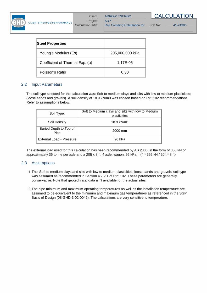
ABPRail Crossing Calculation for ABP
CALCULATION
41-24306
Client: ARROW ENERGY
Calculation Title: Job No:Project:
2.2 Input Parameters
2.3 Assumptions
1
2
External Load - Pressure 96 kPa
Soil Density
Buried Depth to Top ofPipe
Soil Type:
18.9 kN/m³
2000 mm
Soft to Medium clays and silts with low to Mediumplasticities
The external load used for this calculation has been recommended by AS 2885, in the form of 356 kN orapproximately 36 tonne per axle and a 20ft x 8 ft, 4 axle, wagon. 96 kPa = (4 * 356 kN / 20ft * 8 ft)
Steel Properties
Coefficient of Thermal Exp. ( ) 1.17E-05
The 'Soft to medium clays and silts with low to medium plasticities; loose sands and gravels' soil typewas assumed as recommended in Section 4.7.2.1 of RP1102. These parameters are generallyconservative. Note that geotechnical data isn't available for the actual sites.
The pipe minimum and maximum operating temperatures as well as the installation temperature areassumed to be equivalent to the minimum and maximum gas temperatures as referenced in the SGPBasis of Design (08-GHD-3-02-0045). The calculations are very sensitive to temperature.
Poisson's Ratio 0.30
Young's Modulus (Es) 205,000,000 kPa
The soil type selected for the calculation was: Soft to medium clays and silts with low to medium plasticities;(loose sands and gravels). A soil density of 18.9 kN/m3 was chosen based on RP1102 recommendations.Refer to assumptions below.

ABPRail Crossing Calculation for ABP
CALCULATION
41-24306
Client: ARROW ENERGY
Calculation Title: Job No:Project:
3. Calculation Results
The results are summarised below and detailed within Appendix A.
DN 800
DN 1050 (possible upgrade)
Effective stresses are within allowable limitsGirth weld stresses are within fatigue allowable limitsLongitudinal stresses are within fatigue allowable limits
4. Conclusion
5. References
API RP1102 - Steel Pipelines Crossing Railroads and HighwaysAS 2885.1 - Pipelines - Gas and Liquid Petroleum Part 1: Design and Construction, Appendix V
This calulation should be reviewed once the actual requirements of the rail authority are known.
CircumferentialStress (kPa)
CyclicLongitudinalStress (kPa)
Min. WallThickness
(mm)
CyclicCircumferential
Stress (kPa)
Best practice installation techniques, in accordance with API RP1102, are recommended. API RP1102,Section 4.9 recommends the location of longitudinal welds at the 45, 135, 225 or 315 degree position withthe crown at the zero position. Section 4.10 recommends locating girth welds at the crossing at a distance ofat least 3m from the centreline of the tracks.
The pipeline at the rail crossing is adequately designed to resist external loading as per API RP1102.Note that the API RP1102 calculation does not take any credit for added strength due to casings. This isbecause the space between the casing and pipeline is generally filled with a grout / cement, which cantransmit loads from the casing to the pipeline. That is, API RP1102 requires that the pipeline on its own(without casing) be designed to withstand the loads experienced at a rail crossing.
348,92148,002 273,175
CyclicLongitudinalStress (kPa)
CircumferentialStress (kPa)
Effective Stress(kPa)
Allowable Stress(kPa)
349,200
Allowable Stress(kPa)
Effective Stress(kPa)
14.90 57,473
The wall thickness at Railway crossings shall be a minimum of 14.9 mm for DN800 and 19.6 mmfor DN1050.
19.60 52,419 38,097 272,538 347,631 349,200
Min. WallThickness
(mm)
CyclicCircumferential
Stress (kPa)

ABPRail Crossing Calculation for ABP
Project:
Appendix 1 -Railway Crossing Calculation
DN800
CALCULATION
41-24306
Client: ARROW ENERGY
Calculation Title: Job No:

Client: ARROW ENERGY
Project: ARROW ENERGY ABP PIPELINECalculation Title: Rail Crossing Job No: 41-24306
Type / OD (mm) DN800 813.0 2.1E+08 kPaX70 485 1.17E-05 per °C14.9 mm 0.30
Weld Type10.20 MPa
Buried Height 2000 mm
Design FactorInstallation Temperature 21 °CMax Operating Temperature 60 °CMin Operating Temperature -10 °C
Trenched Construction?
Soil Type / DescriptionSoil Unit Weight 18.9 kN/m3
Single or Double Track Crossing? Double
Cyclic Circumferentialstress S-Hr 57473 kPaCylic Long stress S-Lr 48002 kPaCircumferential stress S-Hi 273175 kPaEffective Stress Seff (T2Min) 348921 kPa
Seff (T2Max) 325811 kPa% of Allowable / Limit
99.989
37.89
Pipeline Options
Steel Properties
Other
Pipeline Conditions
Longitudinal weld stresses are within fatigue limits.
Pipeline Results
Recommended value from RP1102: 18.9
Effective stresses are within allowable limits.Girth weld stresses are within fatigue limits.
Design Pressure (MAOP)
Soft to medium clays and silts with low to medium plasticities; loosesands and gravels
Young's Modulus (Es)
0.72
Wall Thickness (tw)
Enter value between 1800 and 4300. If pipe depth > 4300, enter 4300(conservative)
0.72 is used for crossing calc as per AS2885.1-2007 Section 5.7.3 c) (i)
APPENDIX 1
Pipe Grade / SMYS (MPa)Poisson's Ratio (vs)
Seamless and ERW
Coefficient of Thermal Exp. ( )
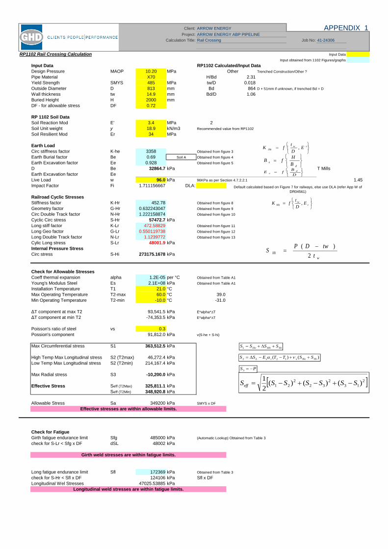
Client: ARROW ENERGY
Project: ARROW ENERGY ABP PIPELINE
Calculation Title: Rail Crossing Job No: 41-24306
RP1102 Rail Crossing Calculation Input Data
Input obtained from 1102 Figures/graphs
Input Data RP1102 Calculated/Input DataDesign Pressure MAOP 10.20 MPa Other Trenched Construction/Other ?
Pipe Material X70 H/Bd 2.31Yield Strength SMYS 485 MPa tw/D 0.018Outside Diameter D 813 mm Bd 864 D + 51mm if unknown, if trenched Bd = D
Wall thickness tw 14.9 mm Bd/D 1.06Buried Height H 2000 mmDF - for allowable stress DF 0.72
RP 1102 Soil DataSoil Reaction Mod E' 3.4 MPa 2Soil Unit weight y 18.9 kN/m3 Recommended value from RP1102
Soil Resilient Mod Er 34 MPa
Earth LoadCirc stiffness factor K-he 3358 Obtained from figure 3
Earth Burial factor Be 0.69 Soil A Obtained from figure 4
Earth Excavation factor Ee 0.928 Obtained from figure 5
D Be 32864.7 kPa T MillsEarth Excavation factor EeLive Load w 96.0 kPa 96KPa as per Section 4.7.2.2.1 1.45Impact Factor Fi 1.711156667 DLA:
Railroad Cyclic StressesStiffness factor K-Hr 452.78 Obtained from figure 8
Geometry factor G-Hr 0.632243047 Obtained from figure 9
Circ Double Track factor N-Hr 1.222158874 Obtained from figure 10
Cyclic Circ stress S-Hr 57472.7 kPaLong stiff factor K-Lr 472.58829 Obtained from figure 11
Long Geo factor G-Lr 0.550119738 Obtained from figure 12
Long Double Track factor N-Lr 1.1239772 Obtained from figure 13
Cylic Long stress S-Lr 48001.9 kPaInternal Pressure StressCirc stress S-Hi 273175.1678 kPa
Check for Allowable StressesCoeff thermal expansion alpha 1.2E-05 per °C Obtained from Table A1
Young's Modulus Steel Es 2.1E+08 kPa Obtained from Table A1
Installation Temperature T1 21.0 °CMax Operating Temperature T2-max 60.0 °C 39.0Min Operating Temperature T2-min -10.0 °C -31.0
T component at max T2 93,541.5 kPa E*alpha* T
T component at min T2 -74,353.5 kPa E*alpha* T
Poisson's ratio of steel vs 0.3Possion's component 91,812.0 kPa v(S-he + S-hi)
Max Circumferential stress S1 363,512.5 kPa
High Temp Max Longitudinal stress S2 (T2max) 46,272.4 kPaLow Temp Max Longitudinal stress S2 (T2min) 214,167.4 kPa
Max Radial stress S3 -10,200.0 kPa
Effective Stress Seff (T2Max) 325,811.1 kPaSeff (T2Min) 348,920.8 kPa
Allowable Stress Sa 349200 kPa SMYS x DF
Check for FatigueGirth fatigue endurance limit Sfg 485000 kPa (Automatic Lookup) Obtained from Table 3
check for S-Lr < Sfg x DF dSL 48002 kPa
Long fatigue endurance limit Sfl 172369 kPa Obtained from Table 3
check for S-Hr < Sfl x DF 124106 kPa Sfl x DFLongitudinal Wel Stresses 47025.53885 kPa
Longitudinal weld stresses are within fatigue limits.
Girth weld stresses are within fatigue limits.
Effective stresses are within allowable limits.
APPENDIX 1
Default calculated based on Figure 7 for railways, else use DLA (refer App W ofDR04561)
', EDt
fK wHe
de B
HfB
DB
fE de
rw
Hh EDtfK ,
wHi t
twDPS2
)(
213
232
221 )()()(
21 SSSSSSSeff
)()( 122 HiHestsL SSTTESS
HiHhHe SSSS1
PS3

ABPRail Crossing Calculation for ABP
Appendix 2 -Railway Crossing Calculation
DN1050
CALCULATIONClient: ARROW ENERGY
Project:Calculation Title: Job No: 41-24306

Client: ARROW ENERGY
Project: ABPCalculation Title: Rail Crossing Calculation for ABP Job No: 41-24306
Type / OD (mm) DN1050 1067.0 2.1E+08 kPaX70 485 1.17E-05 per °C19.6 mm 0.30
Weld Type10.20 MPa
Buried Height 2000 mm
Design FactorInstallation Temperature 21 °CMax Operating Temperature 60 °CMin Operating Temperature -10 °C
Trenched Construction?
Soil Type / DescriptionSoil Unit Weight 18.9 kN/m3
Single or Double Track Crossing? Double
Cyclic Circumferentialstress S-Hr 52419 kPaCylic Long stress S-Lr 38097 kPaCircumferential stress S-Hi 272538 kPaEffective Stress Seff (T2Min) 347631 kPa
Seff (T2Max) 320599 kPa% of Allowable / Limit
99.678
33.13
Soft to medium clays and silts with low to medium plasticities; loosesands and gravels
Young's Modulus (Es)
0.72
Wall Thickness (tw)
Enter value between 1800 and 4300. If pipe depth > 4300, enter 4300(conservative)
Longitudinal weld stresses are within fatigue limits.
Pipeline Results
Recommended value from RP1102: 18.9
Effective stresses are within allowable limits.Girth weld stresses are within fatigue limits.
APPENDIX 1
Pipe Grade / SMYS (MPa)Poisson's Ratio (vs)
Seamless and ERW
Coefficient of Thermal Exp. ( )
Design Pressure (MAOP)
0.72 is used for crossing calc as per AS2885.1-2007 Section 5.7.3 c) (i)
Pipeline Options
Steel Properties
Other
Pipeline Conditions

Client: ARROW ENERGY
Project: ABP
Calculation Title: Rail Crossing Calculation for ABP Job No: 41-24306
RP1102 Rail Crossing Calculation Input Data
Input obtained from 1102 Figures/graphs
Input Data RP1102 Calculated/Input DataDesign Pressure MAOP 10.20 MPa Other Trenched Construction/Other ?
Pipe Material X70 H/Bd 1.79Yield Strength SMYS 485 MPa tw/D 0.018Outside Diameter D 1067 mm Bd 1118 D + 51mm if unknown, if trenched Bd = D
Wall thickness tw 19.6 mm Bd/D 1.05Buried Height H 2000 mmDF - for allowable stress DF 0.72
RP 1102 Soil DataSoil Reaction Mod E' 3.4 MPa 2Soil Unit weight y 18.9 kN/m3 Recommended value from RP1102
Soil Resilient Mod Er 34 MPa
Earth LoadCirc stiffness factor K-he 3346 Obtained from figure 3
Earth Burial factor Be 0.54 Soil A Obtained from figure 4
Earth Excavation factor Ee 0.911 Obtained from figure 5
D Be 33398.3 kPaEarth Excavation factor EeLive Load w 96.0 kPa 96KPa as per Section 4.7.2.2.1 1.45Impact Factor Fi 1.711156667 DLA:
Railroad Cyclic StressesStiffness factor K-Hr 452.47 Obtained from figure 8
Geometry factor G-Hr 0.553161376 Obtained from figure 9
Circ Double Track factor N-Hr 1.274939429 Obtained from figure 10
Cyclic Circ stress S-Hr 52419.2 kPaLong stiff factor K-Lr 472.22724 Obtained from figure 11
Long Geo factor G-Lr 0.380625017 Obtained from figure 12
Long Double Track factor N-Lr 1.290275333 Obtained from figure 13
Cylic Long stress S-Lr 38097.1 kPaInternal Pressure StressCirc stress S-Hi 272537.7551 kPa
Check for Allowable StressesCoeff thermal expansion alpha 1.2E-05 per °C Obtained from Table A1
Young's Modulus Steel Es 2.1E+08 kPa Obtained from Table A1
Installation Temperature T1 21.0 °CMax Operating Temperature T2-max 60.0 °C 39.0Min Operating Temperature T2-min -10.0 °C -31.0
T component at max T2 93,541.5 kPa E*alpha* T
T component at min T2 -74,353.5 kPa E*alpha* T
Poisson's ratio of steel vs 0.3Possion's component 91,780.8 kPa v(S-he + S-hi)
Max Circumferential stress S1 358,355.3 kPa
High Temp Max Longitudinal stress S2 (T2max) 36,336.4 kPaLow Temp Max Longitudinal stress S2 (T2min) 204,231.4 kPa
Max Radial stress S3 -10,200.0 kPa
Effective Stress Seff (T2Max) 320,599.4 kPaSeff (T2Min) 347,631.1 kPa
Allowable Stress Sa 349200 kPa SMYS x DF
Check for FatigueGirth fatigue endurance limit Sfg 485000 kPa (Automatic Lookup) Obtained from Table 3
check for S-Lr < Sfg x DF dSL 38097 kPa
Long fatigue endurance limit Sfl 172369 kPa Obtained from Table 3
check for S-Hr < Sfl x DF 124106 kPa Sfl x DFLongitudinal Wel Stresses 41115.05346 kPa
Longitudinal weld stresses are within fatigue limits.
Girth weld stresses are within fatigue limits.
Effective stresses are within allowable limits.
APPENDIX 1
Default calculated based on Figure 7 for railways, else use DLA (refer App W ofDR04561)
', EDt
fK wHe
de B
HfB
DB
fE de
rw
Hh EDtfK ,
wHi t
twDPS2
)(
213
232
221 )()()(
21 SSSSSSSeff
)()( 122 HiHestsL SSTTESS
HiHhHe SSSS1
PS3


1. Introduction
The design parameters are:DN800DN1050 (possible upgrade)API 5L X70MAOP/Design Pressure 10.2 MPaDesign Temperature: -10 to 60°C
2. Design Basis and Scope
The further requirements of AS2885.1 are covered in separate calculations.
The aim of this calculation is to determine the minimum pipeline wall thickness with respect topenetration resistance by excavators.
The basis for performing this calculation is in accordance with AS 2885.1-2007 Section 5.4.2, whichrequires numerous design, operation and constructability issues to be investigated and (whereapplicable) wall thickness values to be calculated. The wall thickness shall be the greatest of the valuescalculated.
Arrow Energy (the Principal), is proposing to develop a pipeline network in central eastern Queensland thatwill deliver coal seam gas from its gas fields in the Bowen and Surat Basins to a proposed LNG facility to belocated on Curtis Island near Gladstone. The proposed network will be approximately 1,200km long and willincorporate scraper stations and intermediate mainline valves.
A pipeline licence has been granted for the major part of the proposed pipeline from the Surat Basin,however an environment impact assessment of the initial 100km at the start of this pipeline, to the KoganNorth Central Gas Processing Facility near Dalby in south-eastern Queensland, is required.No part of the proposed pipeline from the Bowen Basin has yet been assessed and this preliminaryengineering is associated with the full extent of approx. 610km of pipeline length, the subject of a separatereport.
The ABP system will consist of a DN800 (32”), Class 600 buried steel pipeline.This calculation also reflects a possible future upgrade of the ABP system to a DN1050 (42") pipe diameter.
CALCULATION
41-24306
Client: Arrow Energy
Calculation Title: Resistance to Penetration Job No:ABPProject:
The methods and equations will be used as they appear in the standard when determining the requiredwall thickness for the design pressure of 10.2MPa(g). The wall thickness required to prevent full borerupture and limit the release rate to 10GJ/s will be a factor in the selection of pipe for high consequenceareas.
1
CALCULATION
41-24306
Client: Arrow Energy
Calculation Title: Resistance to Penetration Job No:ABPProject:
3. Assumptions
3.1 Code Related Inputs
3.1.1 Specified Minimum Yield Strength
(Source: API 5L, Table 6)
3.1.2 Pressure Class & PressureA Maximum Allowable Operating Pressure (MAOP) of 10.2 MPa(g) is assumed.
3.2 Design Basis Inputs
3.2.1 Additional Allowances
3.2.2 Location Classes
3.3 Calculation Inputs
The following inputs have been used for the calculations.
Fracture Area - 80 mm2 at V-notch
Young's Modulus - 205,000 MPa
Charpy Impact Energy - 90J (assumed value)
B Factor
- 10 GJ/s = 144 mm
3.3.1 Charpy Impact Energy
X 70
The gas flowing through the pipeline is assumed to be 'Sales Gas' quality. Consequently the gas isdeemed to be 'Non-Corrosive'. Therefore, the pipeline will have a corrosion allowance of 0 mm.
The expected gas composition used in this calculation was specified by Arrow Energy andis in the Design Basis (08-GHD-3-02-0045). To be conservative, the rich gas compositionhas been used.
The calculation determines wall thickness from an assumed Charpy value of 90J based on critical defectlength. The wall thickness due to resistance to penetration has a low sensitivity to this value.
Maximum discharge rate hole diameters (refer Appendix)
- 1.3 for High Consequence Areas. A value of 1.3 has beenselected for conservatism over the equally credible value of 1.0
The largest credible excavator size is assumed to be 35 tonnes.
API Grade SMYS (MPa) UTS (MPa)
It is expected that the route will consist of both rural and high consequence areas. The highconsequence areas may have a variety of location classes however their requirements are common andthey will therefore be grouped together. For this preliminary calculation Sensitive areas (s) and T2 areas,which have a limiting release rate of 1GJ/s, have not been designed for in this calculation.
485 570 (minimum)
2
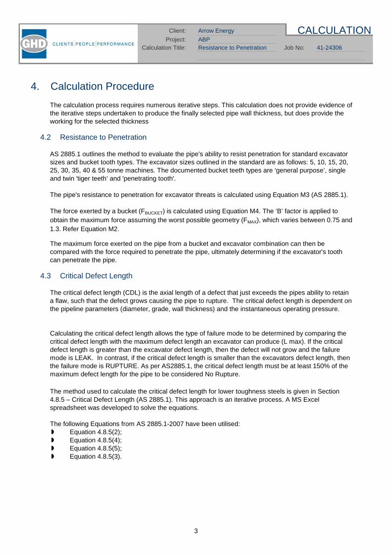
CALCULATION
41-24306
Client: Arrow Energy
Calculation Title: Resistance to Penetration Job No:ABPProject:
4. Calculation Procedure
4.2 Resistance to Penetration
4.3 Critical Defect Length
The following Equations from AS 2885.1-2007 have been utilised:Equation 4.8.5(2);Equation 4.8.5(4);Equation 4.8.5(5);Equation 4.8.5(3).
Calculating the critical defect length allows the type of failure mode to be determined by comparing thecritical defect length with the maximum defect length an excavator can produce (L max). If the criticaldefect length is greater than the excavator defect length, then the defect will not grow and the failuremode is LEAK. In contrast, if the critical defect length is smaller than the excavators defect length, thenthe failure mode is RUPTURE. As per AS2885.1, the critical defect length must be at least 150% of themaximum defect length for the pipe to be considered No Rupture.
The method used to calculate the critical defect length for lower toughness steels is given in Section4.8.5 – Critical Defect Length (AS 2885.1). This approach is an iterative process. A MS Excelspreadsheet was developed to solve the equations.
The force exerted by a bucket (FBUCKET) is calculated using Equation M4. The ‘B’ factor is applied toobtain the maximum force assuming the worst possible geometry (FMAX), which varies between 0.75 and1.3. Refer Equation M2.
The pipe's resistance to penetration for excavator threats is calculated using Equation M3 (AS 2885.1).
AS 2885.1 outlines the method to evaluate the pipe's ability to resist penetration for standard excavatorsizes and bucket tooth types. The excavator sizes outlined in the standard are as follows: 5, 10, 15, 20,25, 30, 35, 40 & 55 tonne machines. The documented bucket teeth types are ‘general purpose’, singleand twin 'tiger teeth’ and 'penetrating tooth'.
The calculation process requires numerous iterative steps. This calculation does not provide evidence ofthe iterative steps undertaken to produce the finally selected pipe wall thickness, but does provide theworking for the selected thickness
The maximum force exerted on the pipe from a bucket and excavator combination can then becompared with the force required to penetrate the pipe, ultimately determining if the excavator's toothcan penetrate the pipe.
The critical defect length (CDL) is the axial length of a defect that just exceeds the pipes ability to retaina flaw, such that the defect grows causing the pipe to rupture. The critical defect length is dependent onthe pipeline parameters (diameter, grade, wall thickness) and the instantaneous operating pressure.
3

CALCULATION
41-24306
Client: Arrow Energy
Calculation Title: Resistance to Penetration Job No:ABPProject:
4.4 Special Provisions for High Consequence Areas
4.4.1 No Rupture
No Rupture is achieved by one of the following:The hoop stress shall not exceed 30% of SMYS or;
4.4.2 Maximum Discharge Rate
5. Calculation Results
5.1 Resistance to Penetration
Pass Pass PassPass Pass Pass
15T 20T 25T 30T 35T 40T 55T
Single Penetration Tooth
Pass Pass Leak Leak
Excavator Weight
5T 10T
Excavator Weight
Pass PassPass Pass Pass Pass
Pass Pass PassPass Pass Pass Pass Pass
The largest equivalent defect is determined for the location class, and the hoop stress at MAOP isselected such that the critical defect length is not less than 150% of the axial length of the largestequivalent defect. This is conservatively applied to part-through wall defects, ie it assumesthat non-leaking defects, of sufficient size, can still lead to rupture. This approach isapproporiate for the purposes of preliminary calculations.
AS 2885.1 Clause 4.7.2 specifies that the pipeline shall be designed such that rupture is not a crediblefailure mode for the following location classes: T1, T2, I, S (and HI areas with the potential for anescalation in consequences). The Safety Management Study (risk assessment) will determine if thepipeline route passes through any of the aforementioned High Consequence Areas.
General Purpose Tooth
35T 40T 55T
General Purpose Tooth
Sensitive (S) locations shall be limited to 1 GJ/s, however these are not considered in this preliminarycalculation.
5T
The results of the resistance to penetration calculation, summarised and tabled below, show that theHigh Consequence pipe cannot be penetrated by a 35T excavator irrespective of tooth type. The wallthickness for pipe in High Consequence areas was set by the CDL requirements listed in Section 5.2
DN800
10T 15T 25T 30TPipe Wall Thickness
AS 2885.1 (Section 4.7.3) specifies that the maximum allowable discharge rate shall not exceed 10 GJ/sin Residential (T1), Industrial (I) and some heavy Industrial (HI) location classes.
20TB = 1.3
15T 20T 25T 30THigh Cons. 68.40% 12.5 mm B = 1.3
Twin Tiger ToothTwin Tiger Tooth
35T 40T 55TPipe Wall Thickness
Pass
B = 1.3
68.40%
Pipe Wall Thickness
5T 10TPass Pass Pass
High Cons. 68.40% 12.5 mm
High Cons. 12.5 mm
Excavator Weight
B = 1.3
4
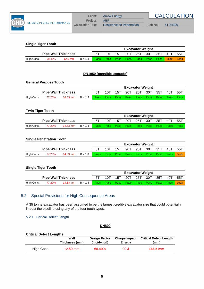
CALCULATION
41-24306
Client: Arrow Energy
Calculation Title: Resistance to Penetration Job No:ABPProject:
5.2 Special Provisions for High Consequence Areas
5.2.1 Critical Defect Length
DN1050 (possible upgrade)
DN800
Pass Pass Pass Pass Pass Leak
35T 40T 55THigh Cons. 77.20% 14.53 mm B = 1.3 Pass Pass Pass
Leak
Single Tiger Tooth
Excavator Weight
Pipe Wall Thickness 5T 10T 15T 20T 25T 30T
Pass Pass Pass Pass Pass Pass
30T 35T 40T 55THigh Cons. 77.20% 14.53 mm B = 1.3 Pass Pass
Pipe Wall Thickness 5T 10T 15T 20T 25T
Pass Pass Pass Pass
Single Penetration Tooth
Excavator Weight
55THigh Cons. 77.20% 14.53 mm B = 1.3 Pass Pass Pass Pass Pass
Excavator Weight
Pipe Wall Thickness 5T 10T 15T 20T 25T 30T 35T 40T
Pass Pass Pass Pass Pass
Twin Tiger Tooth
40T 55THigh Cons. 77.20% 14.53 mm B = 1.3 Pass Pass Pass Pass
General Purpose Tooth
Excavator Weight
Pipe Wall Thickness 5T 10T 15T 20T 25T 30T 35T
WallThickness (mm)
High Cons. 12.50 mm 166.5 mm
Critical Defect Lengths
Pass Pass Pass Pass Pass Pass Pass Leak Leak
Pipe Wall Thickness
Excavator Weight
5T 10T 15T 20T 25T 30T 55T40T40T35T
Design Factor(incidental)
Charpy ImpactEnergy
Critical Defect Length(mm)
68.40% 90 J
B = 1.3
A 35 tonne excavator has been assumed to be the largest credible excavator size that could potentiallyimpact the pipeline using any of the four tooth types.
High Cons. 68.40% 12.5 mm
Single Tiger Tooth
5

CALCULATION
41-24306
Client: Arrow Energy
Calculation Title: Resistance to Penetration Job No:ABPProject:
5.2.2 No Rupture
DN1050 (possible upgrade)
It can be seen that the worst case is for single point contact from a general purpose or tiger tooth bucketand it has been found that 12.5 mm thick pipe for the DN800 and 14.53 mm thick pipe for the DN1050are required to (just) satisfy the 150% rule.
Single Tiger 30 mm 166.4 mm 555%
Penetration 80 mm 166.4 mm 208%
General Purpose 110 mm 166.4 mm 151%
Twin Tiger 110 mm 166.4 mm 151%
High Consequence Pipe (14.53mm) DN105035 Tonne ExcavatorTooth Type Tooth Hole Diameter Critical Defect CDL% of Hole Size
Critical Defect LengthsWall
Thickness (mm)Design Factor
(incidental)Charpy Impact
EnergyCritical Defect Length
(mm)
High Cons. 14.53 mm 77.20% 90 J 166.4 mm
208%
151%
Single Tiger 30 mm 166.5 mm 555%
The No Rupture wall thickness for High Consequence pipe is tabulated below. Even though the pipelinecannot be penetrated by a 35 tonne excavator, the No Rupture requirements for 150% CDL have beenapplied. Consideration has not been given to Facilities and Road / Rail crossing pipe which can occurwithin a High Consequence Area, however it is envisaged that wall thicknesses and subsequently CDLwould be larger.
151%
Penetration 80 mm 166.5 mm
Tooth Hole Diameter Critical Defect35 Tonne ExcavatorHigh Consequence Pipe (12.5mm) DN800
CDL% of Hole Size
Twin Tiger 110 mmTwin Tiger 110 mm
General Purpose 110 mm 166.5 mm
Tooth Type
166.5 mm
6
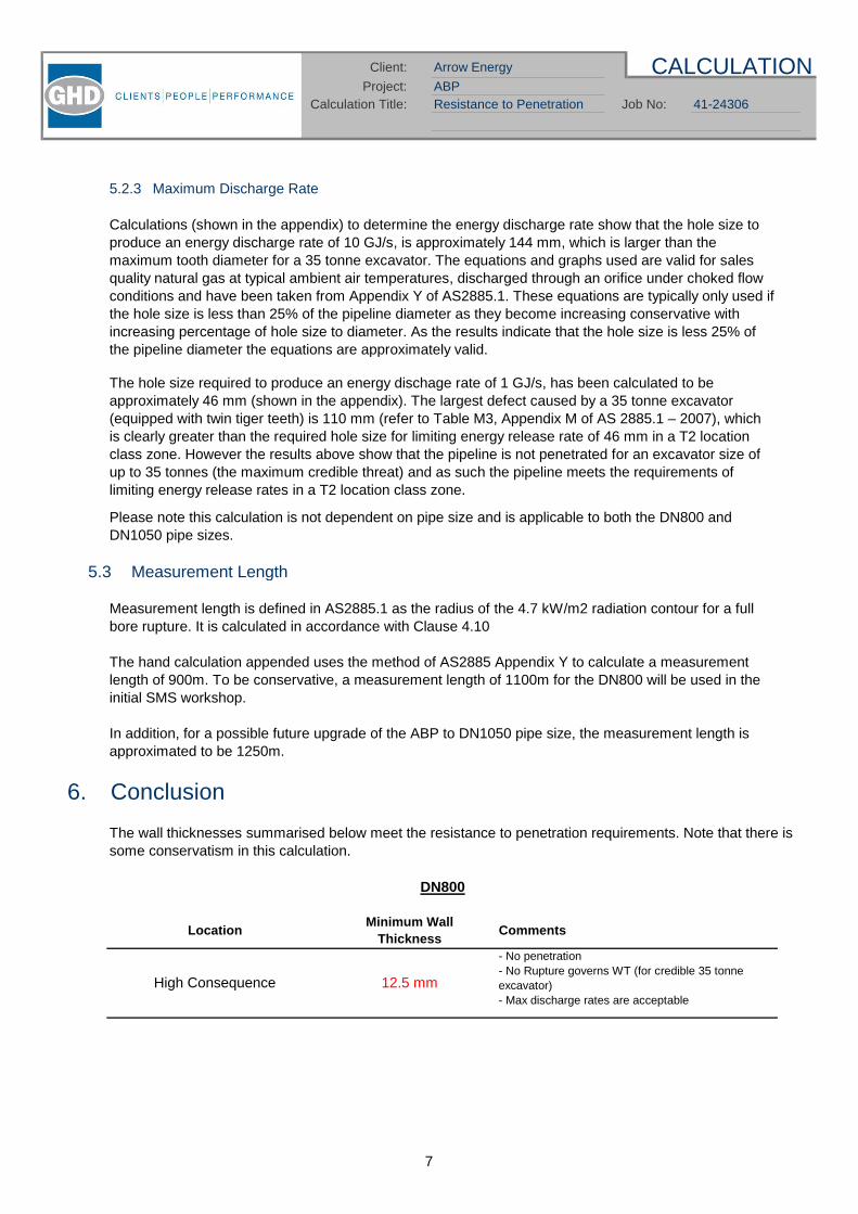
CALCULATION
41-24306
Client: Arrow Energy
Calculation Title: Resistance to Penetration Job No:ABPProject:
5.2.3 Maximum Discharge Rate
5.3 Measurement Length
6. Conclusion
DN800
High Consequence
Minimum WallThickness
12.5 mm
Calculations (shown in the appendix) to determine the energy discharge rate show that the hole size toproduce an energy discharge rate of 10 GJ/s, is approximately 144 mm, which is larger than themaximum tooth diameter for a 35 tonne excavator. The equations and graphs used are valid for salesquality natural gas at typical ambient air temperatures, discharged through an orifice under choked flowconditions and have been taken from Appendix Y of AS2885.1. These equations are typically only used ifthe hole size is less than 25% of the pipeline diameter as they become increasing conservative withincreasing percentage of hole size to diameter. As the results indicate that the hole size is less 25% ofthe pipeline diameter the equations are approximately valid.
Measurement length is defined in AS2885.1 as the radius of the 4.7 kW/m2 radiation contour for a fullbore rupture. It is calculated in accordance with Clause 4.10
The hand calculation appended uses the method of AS2885 Appendix Y to calculate a measurementlength of 900m. To be conservative, a measurement length of 1100m for the DN800 will be used in theinitial SMS workshop.
In addition, for a possible future upgrade of the ABP to DN1050 pipe size, the measurement length isapproximated to be 1250m.
Please note this calculation is not dependent on pipe size and is applicable to both the DN800 andDN1050 pipe sizes.
The hole size required to produce an energy dischage rate of 1 GJ/s, has been calculated to beapproximately 46 mm (shown in the appendix). The largest defect caused by a 35 tonne excavator(equipped with twin tiger teeth) is 110 mm (refer to Table M3, Appendix M of AS 2885.1 – 2007), whichis clearly greater than the required hole size for limiting energy release rate of 46 mm in a T2 locationclass zone. However the results above show that the pipeline is not penetrated for an excavator size ofup to 35 tonnes (the maximum credible threat) and as such the pipeline meets the requirements oflimiting energy release rates in a T2 location class zone.
- No penetration- No Rupture governs WT (for credible 35 tonneexcavator)- Max discharge rates are acceptable
CommentsLocation
The wall thicknesses summarised below meet the resistance to penetration requirements. Note that there issome conservatism in this calculation.
7

CALCULATION
41-24306
Client: Arrow Energy
Calculation Title: Resistance to Penetration Job No:ABPProject:
DN1050 (possible upgrade)
High Consequence 14.5 mm
- No penetration- No Rupture governs WT (for credible 35 tonneexcavator)- Max discharge rates are acceptable
LocationMinimum Wall
ThicknessComments
8

Resistance to Penetration Job No:ABP
AppendixSupporting Calculations
Project:CALCULATION
41-24306
Client: Arrow Energy
Calculation Title:


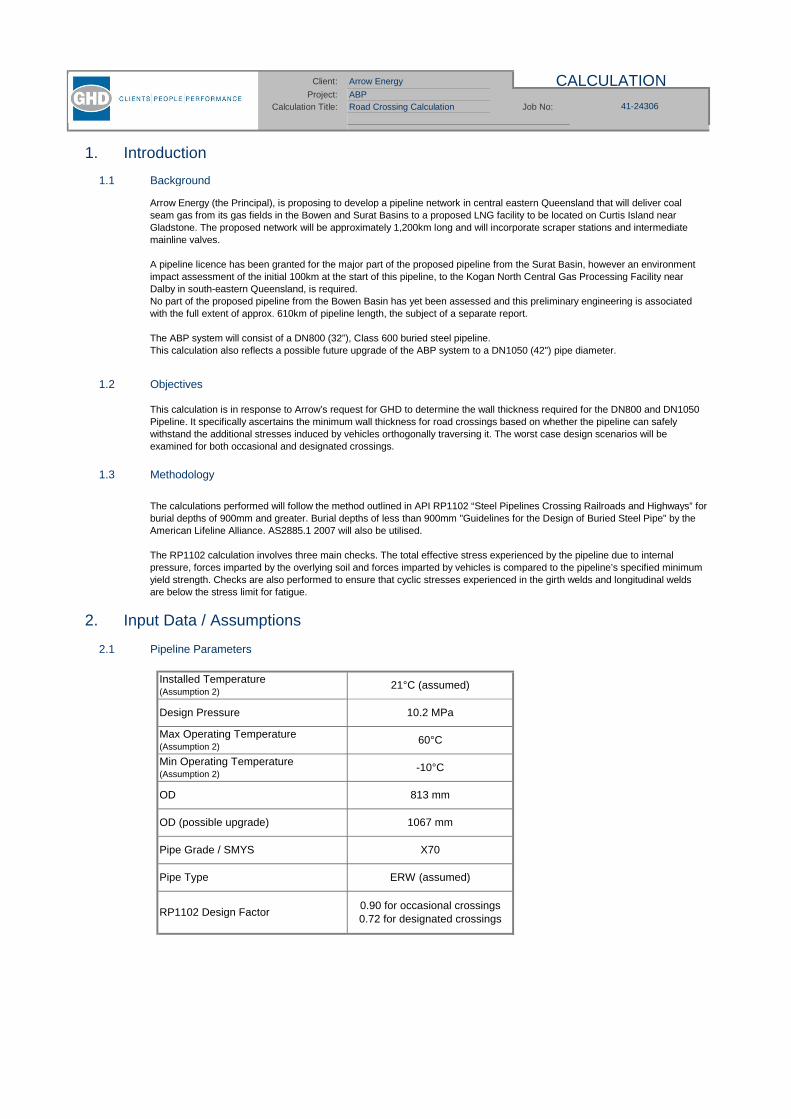
ABPRoad Crossing Calculation
1. Introduction
1.1 Background
1.2 Objectives
1.3 Methodology
2. Input Data / Assumptions
2.1 Pipeline Parameters
41-24306Job No:
Installed Temperature(Assumption 2)
Calculation Title:
21°C (assumed)
X70
Client: Arrow Energy
Max Operating Temperature(Assumption 2)
This calculation is in response to Arrow’s request for GHD to determine the wall thickness required for the DN800 and DN1050Pipeline. It specifically ascertains the minimum wall thickness for road crossings based on whether the pipeline can safelywithstand the additional stresses induced by vehicles orthogonally traversing it. The worst case design scenarios will beexamined for both occasional and designated crossings.
60°C
Min Operating Temperature(Assumption 2)
OD
CALCULATION
Design Pressure
Pipe Type
813 mm
-10°C
Pipe Grade / SMYS
0.90 for occasional crossings0.72 for designated crossings
The calculations performed will follow the method outlined in API RP1102 “Steel Pipelines Crossing Railroads and Highways” forburial depths of 900mm and greater. Burial depths of less than 900mm "Guidelines for the Design of Buried Steel Pipe" by theAmerican Lifeline Alliance. AS2885.1 2007 will also be utilised.
The RP1102 calculation involves three main checks. The total effective stress experienced by the pipeline due to internalpressure, forces imparted by the overlying soil and forces imparted by vehicles is compared to the pipeline’s specified minimumyield strength. Checks are also performed to ensure that cyclic stresses experienced in the girth welds and longitudinal weldsare below the stress limit for fatigue.
Project:
ERW (assumed)
10.2 MPa
RP1102 Design Factor
Arrow Energy (the Principal), is proposing to develop a pipeline network in central eastern Queensland that will deliver coalseam gas from its gas fields in the Bowen and Surat Basins to a proposed LNG facility to be located on Curtis Island nearGladstone. The proposed network will be approximately 1,200km long and will incorporate scraper stations and intermediatemainline valves.
A pipeline licence has been granted for the major part of the proposed pipeline from the Surat Basin, however an environmentimpact assessment of the initial 100km at the start of this pipeline, to the Kogan North Central Gas Processing Facility nearDalby in south-eastern Queensland, is required.No part of the proposed pipeline from the Bowen Basin has yet been assessed and this preliminary engineering is associatedwith the full extent of approx. 610km of pipeline length, the subject of a separate report.
The ABP system will consist of a DN800 (32”), Class 600 buried steel pipeline.This calculation also reflects a possible future upgrade of the ABP system to a DN1050 (42") pipe diameter.
OD (possible upgrade) 1067 mm

ABPRoad Crossing Calculation 41-24306Job No:Calculation Title:
Client: Arrow Energy CALCULATIONProject:
2.2 Steel Parameters
2.3 Soil Parameters
2.4 Vehicle Parameters
2.5 Assumptions
1
2
3
3. Exclusions
Detailed information regarding specific axle loads that may cross the pipeline are yet to be determined however thiscalculation utilises the recommendations from AS2885.1, which equates to a load of approximately 16 tonnes per axle.
Soil Density
Poisson's Ratio 0.30
1.17E-05
Young's Modulus (Es) 205,000 MPa
Buried Depth to Top ofPipe
750mm, 900mm, 1200mm, 1500mm, 2000mm
18.9 kN/m3
Coefficient of Thermal Exp. ( )
Soil Type:Soft to medium clays and silts with low to medium plasticities;
loose sands and gravels
The 'Soft to medium clays and silts with low to medium plasticities; loose sands and gravels' soil type was assumed asrecommended in Section 4.7.2.1 of RP1102. These parameters are generally conservative. Note that geotechnical data isn'tavailable for the actual sites.
The M1600 tandem axle wheel load will always be the worse case when using API RP1102 and therefore calculations will beperformed for only this wheel loading configuration for burial depths of 900mm and above. When using the "Guidelines for theDesign of Buried Steel Pipe" the worse case is the single axle load and therefore calculations will be performed only for thiswheel loading configuration for a burial depth of 750mm.
60 0.08
The pipe minimum and maximum operating temperatures as well as the installation temperature are assumed to be equivalentto the minimum and maximum gas temperatures as referenced in the SGP Basis of Design (08-GHD-3-02-0045). Thecalculations are very sensitive to temperature.
Description
W80 (single axle)
M1600(tandem axle)
Wheel Load (kN)
80
Wheel Contact
Area (m2)
0.10
This calculation report excludes special crossings.
The soil type selected for the calculation was: Soft to medium clays and silts with low to medium plasticities; (loose sands andgravels). A soil density of 18.9 kN/m3 was chosen based on RP1102 recommendations. Refer to assumptions below.
Specific information regarding crossings has not yet been determined. Typical values for the pipelines burial depth atcrossings has therefore been used.
As an unsealed surface does not spread the load as well as a sealed surface it will be used as the design input for 'pavementtype'. This will produce slightly conservative results for the major road crossings with engineered pavements.

ABPRoad Crossing Calculation 41-24306Job No:Calculation Title:
Client: Arrow Energy CALCULATIONProject:
4. Results Summary
DN800
DN1050 (possible upgrade)
5. Conclusion
6. References
API RP1102 - Steel Pipelines Crossing Railroads and HighwaysAS 2885.1 - Pipelines - Gas and Liquid Petroleum Part 1: Design and Construction, Appendix VGuidelines for the Design of Buried Steel Pipe - American Lifeline Alliance.
It is noted that the RP1102 calculation calls for higher wall thickness at deeper covers for any given wheel load. This counter-intuitive result has been encountered before and is a function of the way in which the method penalises increasing soil weight at afaster rate than it credits decreasing wheel load intensity as depth increases.
WheelLoad(kN)
No Pavement
60
Detailed Results are shown in the Appendix
No Pavement 0.9 10.3
RP1102DesignFactor
WallThickness
(mm)
Depth ofCoverage
(mm)NotesPavement
Tandem
Axle TypeMAOP
(MPa(g))
10.2
0.72 13.610.2
M1600 design load
M1600 design load
10.2
Tandem
900
0.9
No Pavement 0.72
11.0
M1600 design load60 1200 Tandem No Pavement
60 2000
13.8 M1600 design load10.2 60
RP1102DesignFactor
WallThickness
(mm)Notes
1500 Tandem
MAOP(MPa(g))
WheelLoad(kN)
Depth ofCoverage
(mm)Axle Type Pavement
10.2 60 900 Tandem No Pavement 0.9 13.4 M1600 design load
10.2 60 2000 Tandem No Pavement 0.9 14.3 M1600 design load
18.0 M1600 design load
10.2 60 1200 Tandem No Pavement 0.72
10.2 60 1500 Tandem No Pavement 0.72
As previously mentioned a separate method and guidelines were used for burial depths less than 900mm. According to thismethod, at a burial depth of 750mm, a wall thickness in excess of 11.0mm for DN800 and 13.0mm for DN1050 is needed to protectthe integrity of the pipeline and procedural controls will be required to control the occurrence of the 80kN load at random"occasional" crossings along the route. No attempt will be made to increase the R1/R2 locations wall thickness in order to resistsuch loads.
The primary objective of this report was to determine the minimum wall thickness required for Arrow's DN800 and DN1050 pipeline tosafely withstand the stress induced by design vehicles orthogonally traversing it. Calculations were performed in line with API RP1102,AS 2885.1-2007 and Guidelines for the Design of Buried Steel Pipe. The calculation determined that the minimum allowable wallthickness for occasional crossings is 11.0mm for DN800 and 14.3mm for DN1050 at depths of 900mm and greater. It is recommendedthat this combination of 11.0mm/14.3mm and 900mm be used globally in an effort to provide resistance to vehicular loads. If the pipewere to be buried at a depth smaller than 900mm, additional procedural controls will be required.
This calculation determined that the minimum wall thickness for designated road crossings is 13.8mm for DN800 and18.0mm for DN1050. In the event that specific road crossings and loads are identified at a later stage, additional protection measuressuch as concrete slabs should be considered.
Design
Loads
Occ
assi
on
alC
ross
ing
Des
ign
ated
Cro
ssin
g
Design
Loads
Occ
assi
on
alC
ross
ing
Des
ign
ated
Cro
ssin
g 17.8 M1600 design load
ABP
Appendix 1 - Calculation SummaryDN800
CALCULATIONClient: Arrow Energy
Calculation Title: Job No: 41-24306Project:
Road Crossing Calculation
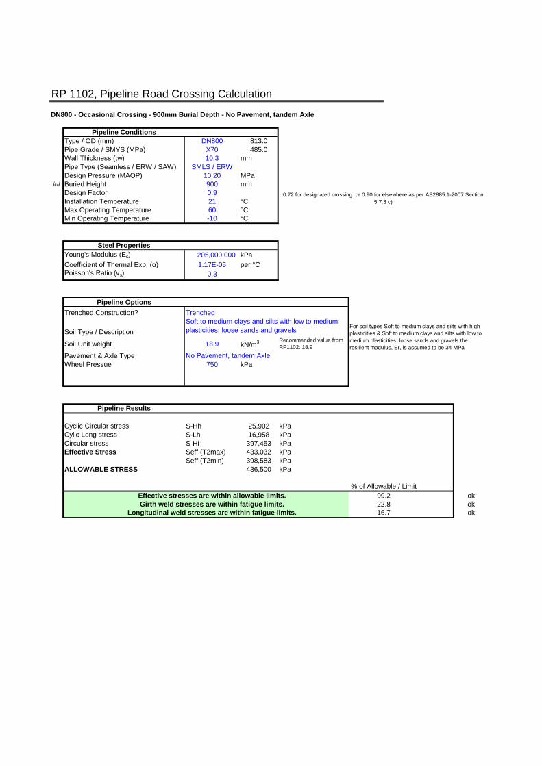
RP 1102, Pipeline Road Crossing Calculation
DN800 - Occasional Crossing - 900mm Burial Depth - No Pavement, tandem Axle
Pipeline ConditionsType / OD (mm) DN800 813.0Pipe Grade / SMYS (MPa) X70 485.0Wall Thickness (tw) 10.3 mmPipe Type (Seamless / ERW / SAW) SMLS / ERWDesign Pressure (MAOP) 10.20 MPa
## Buried Height 900 mmDesign Factor 0.9Installation Temperature 21 °CMax Operating Temperature 60 °CMin Operating Temperature -10 °C
Steel PropertiesYoung's Modulus (Es) 205,000,000 kPa
Coefficient of Thermal Exp. ( ) 1.17E-05 per °CPoisson's Ratio (vs) 0.3
Pipeline Options
Trenched Construction?
Soil Type / Description
Soil Unit weight 18.9 kN/m3 Recommended value fromRP1102: 18.9
Pavement & Axle TypeWheel Pressue 750 kPa
Pipeline Results
Cyclic Circular stress S-Hh 25,902 kPaCylic Long stress S-Lh 16,958 kPaCircular stress S-Hi 397,453 kPaEffective Stress Seff (T2max) 433,032 kPa
Seff (T2min) 398,583 kPaALLOWABLE STRESS 436,500 kPa
Effective stresses are within allowable limits. okGirth weld stresses are within fatigue limits. ok
Longitudinal weld stresses are within fatigue limits. ok
Trenched
No Pavement, tandem Axle
Soft to medium clays and silts with low to mediumplasticities; loose sands and gravels
0.72 for designated crossing or 0.90 for elsewhere as per AS2885.1-2007 Section5.7.3 c)
16.7
% of Allowable / Limit
For soil types Soft to medium clays and silts with highplasticities & Soft to medium clays and silts with low tomedium plasticities; loose sands and gravels theresilient modulus, Er, is assumed to be 34 MPa
99.222.8

API RP1102 Road crossing calculation 16/08/2011
RP1102 Road Crossing Calculation DN800 - Occasional Crossing - 900mm Burial Depth - No Pavement, tandem Axle
Input Data RP1102 Calculated/Input DataDesign Pressure MAOP 10.20 MPa Trenched Trenched Construction/Other ?
Pipe Material X70 H/Bd 1.11Yield Strength SMYS 485 MPa tw/D 0.013Outside Diameter D 813 mm Bd 813 mm D + 51mm if unknown, if trenched Bd = D
Wall thickness tw 10.3 mm Bd/D 1.00Pipe Type SMLS / ERWBuried Height H 900 mm No Pavement, tandem Axle Tandem Select pavement type and hence axle configuration from Table 1
DF - for allowable stress DF 0.9 % R 1.1 Select from Table 2
L 1 Select from Table 2
RP 1102 Soil DataSoil Type Soft to medium clays and silts with low to medium plasticities; loose sands and gravelsSoil Reaction Mod E' 3.4 MPa 2Soil Unit weight y 18.9 kN/m3 Recommended value from RP1102
Soil Resilient Mod Er 34 MPa Assumption based upon soil type
Earth LoadCirc stiffness factor K-he 5267.92 Obtained from figure 3
Earth Burial factor Be 0.3297 Soil A Obtained from figure 4
Earth Excavation factor Ee 1.0000 Obtained from figure 5
Earth Load S-he 26686.6 kPa
Live LoadAxle Load Pa 0 tonnes/axle
Tandem axle wheel load Pt 0 tonnes insert value if known
Single axle wheel load Ps 0 tonnes insert value if known
Design wheel load P kN Based on selection of tandem or single per above
Wheel contact area Ap 0 m2 Default figure is from RP1102 (0.093m2), user can select otherwise
Live Load w 750.0 kPaImpact Factor Fi 1.5 DLA: Default calculated based on Figure 7 for highways, else use DLA (refer App W of DR04561) 1.5
Highway Cyclic StressesCirc Highway stiff factor K-Hh 20.63 Obtained from figure 14
Circ Highway Geo factor G-Hh 1.01 Obtained from figure 15
Cyclic Circ stress S-Hh 25901.8 kPaLong Highway stiff factor K-Lh 14.8699 Obtained from figure 16
Long Highway Geo factor G-Lh 0.9216 Obtained from figure 17
Cylic Long stress S-Lh 16958.3 kPaInternal Pressure StressCirc stress S-Hi 397453.3981 kPa
Check for Allowable StressesCoeff thermal expansion alpha 1.2E-05 per °C Obtained from Table A1
Young's Modulus Steel Es 2.05E+08 kPa Obtained from Table A1
Installation Temperature T1 21.0 °CMax Operating Temperature T2-max 60.0 °CMin Operating Temperature T2-min -10.0 °C
T component at max T2 93,541.5 kPa E*alpha* T
T component at min T2 -74,353.5 kPa E*alpha* T
Poisson's ratio of steel vs 0.3Possion's component 127,242.0 kPa v(S-he + S-hi)
Max Circumferential stress S1 450,041.8 kPaMax Longitudinal stress S2 (T2max) 50,658.8 kPa
S2 (T2min) 218,553.8 kPaMax Radial stress S3 -10,200.0 kPa
Effective Stress Seff (T2max) 433,031.8 kPaSeff (T2min) 398,583.4 kPa
Allowable Stress Sa 436500 kPa SMYS x DF
Effective stresses are within allowable limits. ok
Check for FatigueGirth fatigue endurance limit Sfg 82737 kPa Obtained from Table 3
check for S-Lh < Sfg x DF 74463.4 kPa Sfg x DFGirth weld stresses are within fatigue limits. ok
Long fatigue endurance limit Sfl 172369 kPa Obtained from Table 3
check for S-Hh < Sfl x DF 155132 kPaLongitudinal weld stresses are within fatigue limits. ok
Value used to determine design wheel load. If chosen value results in design wheel load <80kN, 80kN is used in accordance with recommendation in AS2885.1 V4
213
232
221 )()()(
21 SSSSSSSeff
)()( 122 HiHestsL SSTTESS
HiHhHe SSSS1
PS3
', EDt
fK wHe
de B
HfB
DB
fE de
rw
Hh EDt
fK ,
w
wHi t
tDPS2
)(

RP 1102, Pipeline Road Crossing Calculation
DN800 - Occasional Crossing - 2000mm Burial Depth - No Pavement, tandem Axle
Pipeline ConditionsType / OD (mm) DN800 813.0Pipe Grade / SMYS (MPa) X70 485.0Wall Thickness (tw) 11 mmPipe Type (Seamless / ERW / SAW) SMLS / ERWDesign Pressure (MAOP) 10.20 MPa
## Buried Height 2000 mmDesign Factor 0.9Installation Temperature 21 °CMax Operating Temperature 60 °CMin Operating Temperature -10 °C
Steel PropertiesYoung's Modulus (Es) 205,000,000 kPa
Coefficient of Thermal Exp. ( ) 1.17E-05 per °CPoisson's Ratio (vs) 0.3
Pipeline Options
Trenched Construction?
Soil Type / Description
Soil Unit weight 18.9 kN/m3 Recommended value fromRP1102: 18.9
Pavement & Axle TypeWheel Pressue 750 kPa
Pipeline Results
Cyclic Circular stress S-Hh 17,841 kPaCylic Long stress S-Lh 13,393 kPaCircular stress S-Hi 371,836 kPaEffective Stress Seff (T2max) 428,737 kPa
Seff (T2min) 393,886 kPaALLOWABLE STRESS 436,500 kPa
Effective stresses are within allowable limits. okGirth weld stresses are within fatigue limits. ok
Longitudinal weld stresses are within fatigue limits. ok11.5
% of Allowable / Limit
For soil types Soft to medium clays and silts with highplasticities & Soft to medium clays and silts with low tomedium plasticities; loose sands and gravels theresilient modulus, Er, is assumed to be 34 MPa
98.218.0
Trenched
No Pavement, tandem Axle
Soft to medium clays and silts with low to mediumplasticities; loose sands and gravels
0.72 for designated crossing or 0.90 for elsewhere as per AS2885.1-2007 Section5.7.3 c)

API RP1102 Road crossing calculation 16/08/2011
RP1102 Road Crossing Calculation DN800 - Occasional Crossing - 2000mm Burial Depth - No Pavement, tandem Axle
Input Data RP1102 Calculated/Input DataDesign Pressure MAOP 10.20 MPa Trenched Trenched Construction/Other ?
Pipe Material X70 H/Bd 2.46Yield Strength SMYS 485 MPa tw/D 0.014Outside Diameter D 813 mm Bd 813 mm D + 51mm if unknown, if trenched Bd = D
Wall thickness tw 11 mm Bd/D 1.00Pipe Type SMLS / ERWBuried Height H 2000 mm No Pavement, tandem Axle Tandem Select pavement type and hence axle configuration from Table 1
DF - for allowable stress DF 0.9 % R 1.1 Select from Table 2
L 1 Select from Table 2
RP 1102 Soil DataSoil Type Soft to medium clays and silts with low to medium plasticities; loose sands and gravelsSoil Reaction Mod E' 3.4 MPa 2Soil Unit weight y 18.9 kN/m3 Recommended value from RP1102
Soil Resilient Mod Er 34 MPa Assumption based upon soil type
Earth LoadCirc stiffness factor K-he 4891.04 Obtained from figure 3
Earth Burial factor Be 0.7310 Soil A Obtained from figure 4
Earth Excavation factor Ee 1.0000 Obtained from figure 5
Earth Load S-he 54940.4 kPa
Live LoadAxle Load Pa 0 tonnes/axle
Tandem axle wheel load Pt 0 tonnes insert value if known
Single axle wheel load Ps 0 tonnes insert value if known
Design wheel load P kN Based on selection of tandem or single per above
Wheel contact area Ap 0 m2 Default figure is from RP1102 (0.093m2), user can select otherwise
Live Load w 750.0 kPaImpact Factor Fi 1.45 DLA: Default calculated based on Figure 7 for highways, else use DLA (refer App W of DR04561) 1.45
Highway Cyclic StressesCirc Highway stiff factor K-Hh 20.68 Obtained from figure 14
Circ Highway Geo factor G-Hh 0.72 Obtained from figure 15
Cyclic Circ stress S-Hh 17841.1 kPaLong Highway stiff factor K-Lh 14.9413 Obtained from figure 16
Long Highway Geo factor G-Lh 0.7493 Obtained from figure 17
Cylic Long stress S-Lh 13393.0 kPaInternal Pressure StressCirc stress S-Hi 371836.3636 kPa
Check for Allowable StressesCoeff thermal expansion alpha 1.2E-05 per °C Obtained from Table A1
Young's Modulus Steel Es 2.05E+08 kPa Obtained from Table A1
Installation Temperature T1 21.0 °CMax Operating Temperature T2-max 60.0 °CMin Operating Temperature T2-min -10.0 °C
T component at max T2 93,541.5 kPa E*alpha* T
T component at min T2 -74,353.5 kPa E*alpha* T
Poisson's ratio of steel vs 0.3Possion's component 128,033.0 kPa v(S-he + S-hi)
Max Circumferential stress S1 444,617.8 kPaMax Longitudinal stress S2 (T2max) 47,884.5 kPa
S2 (T2min) 215,779.5 kPaMax Radial stress S3 -10,200.0 kPa
Effective Stress Seff (T2max) 428,736.7 kPaSeff (T2min) 393,886.4 kPa
Allowable Stress Sa 436500 kPa SMYS x DF
Effective stresses are within allowable limits. ok
Check for FatigueGirth fatigue endurance limit Sfg 82737 kPa Obtained from Table 3
check for S-Lh < Sfg x DF 74463.4 kPa Sfg x DFGirth weld stresses are within fatigue limits. ok
Long fatigue endurance limit Sfl 172369 kPa Obtained from Table 3
check for S-Hh < Sfl x DF 155132 kPaLongitudinal weld stresses are within fatigue limits. ok
Value used to determine design wheel load. If chosen value results in design wheel load <80kN, 80kN is used in accordance with recommendation in AS2885.1 V4
213
232
221 )()()(
21 SSSSSSSeff
)()( 122 HiHestsL SSTTESS
HiHhHe SSSS1
PS3
', EDt
fK wHe
de B
HfB
DB
fE de
rw
Hh EDt
fK ,
w
wHi t
tDPS2
)(

RP 1102, Pipeline Road Crossing Calculation
DN800 - Designated Crossing - 1200mm Burial Depth - No Pavement, tandem Axle
Pipeline ConditionsType / OD (mm) DN800 813.0Pipe Grade / SMYS (MPa) X70 485.0Wall Thickness (tw) 13.6 mmPipe Type (Seamless / ERW / SAW) SMLS / ERWDesign Pressure (MAOP) 10.20 MPa
## Buried Height 1200 mmDesign Factor 0.72Installation Temperature 21 °CMax Operating Temperature 60 °CMin Operating Temperature -10 °C
Steel PropertiesYoung's Modulus (Es) 205,000,000 kPa
Coefficient of Thermal Exp. ( ) 1.17E-05 per °CPoisson's Ratio (vs) 0.3
Pipeline Options
Trenched Construction?
Soil Type / Description
Soil Unit weight 18.9 kN/m3 Recommended value fromRP1102: 18.9
Pavement & Axle TypeWheel Pressue 750 kPa
Pipeline Results
Cyclic Circular stress S-Hh 25,682 kPaCylic Long stress S-Lh 16,852 kPaCircular stress S-Hi 299,775 kPaEffective Stress Seff (T2max) 347,839 kPa
Seff (T2min) 314,474 kPaALLOWABLE STRESS 349,200 kPa
Effective stresses are within allowable limits. okGirth weld stresses are within fatigue limits. ok
Longitudinal weld stresses are within fatigue limits. ok20.7
% of Allowable / Limit
For soil types Soft to medium clays and silts with highplasticities & Soft to medium clays and silts with low tomedium plasticities; loose sands and gravels theresilient modulus, Er, is assumed to be 34 MPa
99.628.3
Trenched
No Pavement, tandem Axle
Soft to medium clays and silts with low to mediumplasticities; loose sands and gravels
0.72 for designated crossing or 0.90 for elsewhere as per AS2885.1-2007 Section5.7.3 c)

API RP1102 Road crossing calculation 16/08/2011
RP1102 Road Crossing Calculation DN800 - Designated Crossing - 1200mm Burial Depth - No Pavement, tandem Axle
Input Data RP1102 Calculated/Input DataDesign Pressure MAOP 10.20 MPa Trenched Trenched Construction/Other ?
Pipe Material X70 H/Bd 1.48Yield Strength SMYS 485 MPa tw/D 0.017Outside Diameter D 813 mm Bd 813 mm D + 51mm if unknown, if trenched Bd = D
Wall thickness tw 13.6 mm Bd/D 1.00Pipe Type SMLS / ERWBuried Height H 1200 mm No Pavement, tandem Axle Tandem Select pavement type and hence axle configuration from Table 1
DF - for allowable stress DF 0.72 % R 1.1 Select from Table 2
L 1 Select from Table 2
RP 1102 Soil DataSoil Type Soft to medium clays and silts with low to medium plasticities; loose sands and gravelsSoil Reaction Mod E' 3.4 MPa 2Soil Unit weight y 18.9 kN/m3 Recommended value from RP1102
Soil Resilient Mod Er 34 MPa Assumption based upon soil type
Earth LoadCirc stiffness factor K-he 3819.49 Obtained from figure 3
Earth Burial factor Be 0.4577 Soil A Obtained from figure 4
Earth Excavation factor Ee 1.0000 Obtained from figure 5
Earth Load S-he 26861.9 kPa
Live LoadAxle Load Pa 0 tonnes/axle
Tandem axle wheel load Pt 0 tonnes insert value if known
Single axle wheel load Ps 0 tonnes insert value if known
Design wheel load P kN Based on selection of tandem or single per above
Wheel contact area Ap 0 m2 Default figure is from RP1102 (0.093m2), user can select otherwise
Live Load w 750.0 kPaImpact Factor Fi 1.5 DLA: Default calculated based on Figure 7 for highways, else use DLA (refer App W of DR04561) 1.5
Highway Cyclic StressesCirc Highway stiff factor K-Hh 20.46 Obtained from figure 14
Circ Highway Geo factor G-Hh 1.01 Obtained from figure 15
Cyclic Circ stress S-Hh 25681.9 kPaLong Highway stiff factor K-Lh 14.7770 Obtained from figure 16
Long Highway Geo factor G-Lh 0.9216 Obtained from figure 17
Cylic Long stress S-Lh 16852.3 kPaInternal Pressure StressCirc stress S-Hi 299775 kPa
Check for Allowable StressesCoeff thermal expansion alpha 1.2E-05 per °C Obtained from Table A1
Young's Modulus Steel Es 2.05E+08 kPa Obtained from Table A1
Installation Temperature T1 21.0 °CMax Operating Temperature T2-max 60.0 °CMin Operating Temperature T2-min -10.0 °C
T component at max T2 93,541.5 kPa E*alpha* T
T component at min T2 -74,353.5 kPa E*alpha* T
Poisson's ratio of steel vs 0.3Possion's component 97,991.1 kPa v(S-he + S-hi)
Max Circumferential stress S1 352,318.8 kPaMax Longitudinal stress S2 (T2max) 21,301.9 kPa
S2 (T2min) 189,196.9 kPaMax Radial stress S3 -10,200.0 kPa
Effective Stress Seff (T2max) 347,839.4 kPaSeff (T2min) 314,474.0 kPa
Allowable Stress Sa 349200 kPa SMYS x DF
Effective stresses are within allowable limits. ok
Check for FatigueGirth fatigue endurance limit Sfg 82737 kPa Obtained from Table 3
check for S-Lh < Sfg x DF 59570.7 kPa Sfg x DFGirth weld stresses are within fatigue limits. ok
Long fatigue endurance limit Sfl 172369 kPa Obtained from Table 3
check for S-Hh < Sfl x DF 124105.6 kPaLongitudinal weld stresses are within fatigue limits. ok
Value used to determine design wheel load. If chosen value results in design wheel load <80kN, 80kN is used in accordance with recommendation in AS2885.1 V4
213
232
221 )()()(
21 SSSSSSSeff
)()( 122 HiHestsL SSTTESS
HiHhHe SSSS1
PS3
', EDt
fK wHe
de B
HfB
DB
fE de
rw
Hh EDt
fK ,
w
wHi t
tDPS2
)(

RP 1102, Pipeline Road Crossing Calculation
DN800 - Designated Crossing - 1500mm Burial Depth - No Pavement, tandem Axle
Pipeline ConditionsType / OD (mm) DN800 813.0Pipe Grade / SMYS (MPa) X70 485.0Wall Thickness (tw) 13.8 mmPipe Type (Seamless / ERW / SAW) SMLS / ERWDesign Pressure (MAOP) 10.20 MPa
## Buried Height 1500 mmDesign Factor 0.72Installation Temperature 21 °CMax Operating Temperature 60 °CMin Operating Temperature -10 °C
Steel PropertiesYoung's Modulus (Es) 205,000,000 kPa
Coefficient of Thermal Exp. ( ) 1.17E-05 per °CPoisson's Ratio (vs) 0.3
Pipeline Options
Trenched Construction?
Soil Type / Description
Soil Unit weight 18.9 kN/m3 Recommended value fromRP1102: 18.9
Pavement & Axle TypeWheel Pressue 750 kPa
Pipeline Results
Cyclic Circular stress S-Hh 22,513 kPaCylic Long stress S-Lh 15,610 kPaCircular stress S-Hi 295,357 kPaEffective Stress Seff (T2max) 346,286 kPa
Seff (T2min) 312,806 kPaALLOWABLE STRESS 349,200 kPa
Effective stresses are within allowable limits. okGirth weld stresses are within fatigue limits. ok
Longitudinal weld stresses are within fatigue limits. ok18.1
% of Allowable / Limit
For soil types Soft to medium clays and silts with highplasticities & Soft to medium clays and silts with low tomedium plasticities; loose sands and gravels theresilient modulus, Er, is assumed to be 34 MPa
99.226.2
Trenched
No Pavement, tandem Axle
Soft to medium clays and silts with low to mediumplasticities; loose sands and gravels
0.72 for designated crossing or 0.90 for elsewhere as per AS2885.1-2007 Section5.7.3 c)
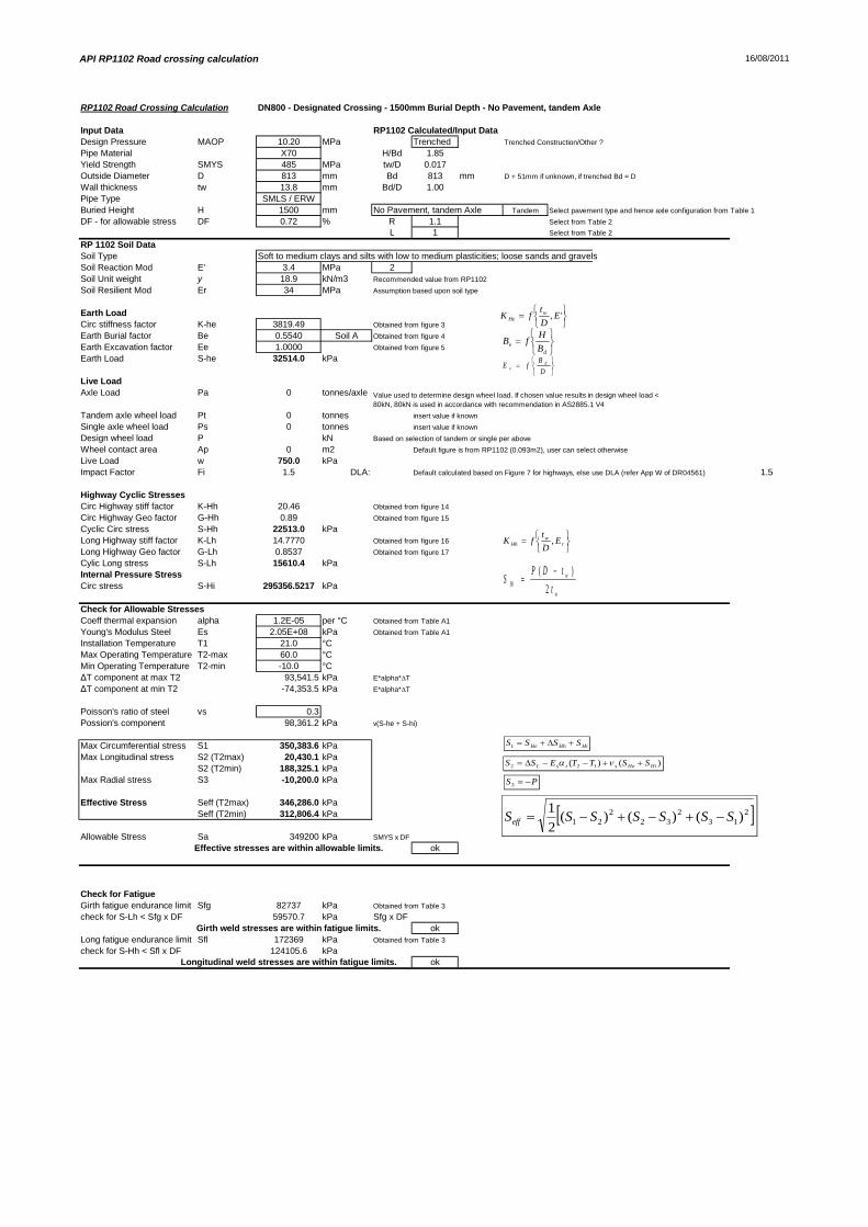
API RP1102 Road crossing calculation 16/08/2011
RP1102 Road Crossing Calculation DN800 - Designated Crossing - 1500mm Burial Depth - No Pavement, tandem Axle
Input Data RP1102 Calculated/Input DataDesign Pressure MAOP 10.20 MPa Trenched Trenched Construction/Other ?
Pipe Material X70 H/Bd 1.85Yield Strength SMYS 485 MPa tw/D 0.017Outside Diameter D 813 mm Bd 813 mm D + 51mm if unknown, if trenched Bd = D
Wall thickness tw 13.8 mm Bd/D 1.00Pipe Type SMLS / ERWBuried Height H 1500 mm No Pavement, tandem Axle Tandem Select pavement type and hence axle configuration from Table 1
DF - for allowable stress DF 0.72 % R 1.1 Select from Table 2
L 1 Select from Table 2
RP 1102 Soil DataSoil Type Soft to medium clays and silts with low to medium plasticities; loose sands and gravelsSoil Reaction Mod E' 3.4 MPa 2Soil Unit weight y 18.9 kN/m3 Recommended value from RP1102
Soil Resilient Mod Er 34 MPa Assumption based upon soil type
Earth LoadCirc stiffness factor K-he 3819.49 Obtained from figure 3
Earth Burial factor Be 0.5540 Soil A Obtained from figure 4
Earth Excavation factor Ee 1.0000 Obtained from figure 5
Earth Load S-he 32514.0 kPa
Live LoadAxle Load Pa 0 tonnes/axle
Tandem axle wheel load Pt 0 tonnes insert value if known
Single axle wheel load Ps 0 tonnes insert value if known
Design wheel load P kN Based on selection of tandem or single per above
Wheel contact area Ap 0 m2 Default figure is from RP1102 (0.093m2), user can select otherwise
Live Load w 750.0 kPaImpact Factor Fi 1.5 DLA: Default calculated based on Figure 7 for highways, else use DLA (refer App W of DR04561) 1.5
Highway Cyclic StressesCirc Highway stiff factor K-Hh 20.46 Obtained from figure 14
Circ Highway Geo factor G-Hh 0.89 Obtained from figure 15
Cyclic Circ stress S-Hh 22513.0 kPaLong Highway stiff factor K-Lh 14.7770 Obtained from figure 16
Long Highway Geo factor G-Lh 0.8537 Obtained from figure 17
Cylic Long stress S-Lh 15610.4 kPaInternal Pressure StressCirc stress S-Hi 295356.5217 kPa
Check for Allowable StressesCoeff thermal expansion alpha 1.2E-05 per °C Obtained from Table A1
Young's Modulus Steel Es 2.05E+08 kPa Obtained from Table A1
Installation Temperature T1 21.0 °CMax Operating Temperature T2-max 60.0 °CMin Operating Temperature T2-min -10.0 °C
T component at max T2 93,541.5 kPa E*alpha* T
T component at min T2 -74,353.5 kPa E*alpha* T
Poisson's ratio of steel vs 0.3Possion's component 98,361.2 kPa v(S-he + S-hi)
Max Circumferential stress S1 350,383.6 kPaMax Longitudinal stress S2 (T2max) 20,430.1 kPa
S2 (T2min) 188,325.1 kPaMax Radial stress S3 -10,200.0 kPa
Effective Stress Seff (T2max) 346,286.0 kPaSeff (T2min) 312,806.4 kPa
Allowable Stress Sa 349200 kPa SMYS x DF
Effective stresses are within allowable limits. ok
Check for FatigueGirth fatigue endurance limit Sfg 82737 kPa Obtained from Table 3
check for S-Lh < Sfg x DF 59570.7 kPa Sfg x DFGirth weld stresses are within fatigue limits. ok
Long fatigue endurance limit Sfl 172369 kPa Obtained from Table 3
check for S-Hh < Sfl x DF 124105.6 kPaLongitudinal weld stresses are within fatigue limits. ok
Value used to determine design wheel load. If chosen value results in design wheel load <80kN, 80kN is used in accordance with recommendation in AS2885.1 V4
213
232
221 )()()(
21 SSSSSSSeff
)()( 122 HiHestsL SSTTESS
HiHhHe SSSS1
PS3
', EDt
fK wHe
de B
HfB
DB
fE de
rw
Hh EDt
fK ,
w
wHi t
tDPS2
)(

Guidlines for the Design of Buried Steel Pipe, Pipeline Road Crossing Calculation
DN800 - Occasional Crossing - 750mm Burial Depth - No Pavement, single axle
Pipeline ConditionsType / OD (mm) DN800 813.0Pipe Grade / SMYS (MPa) X70 485.0Wall Thickness (tw) 12.8 mmPipe Type (Seamless / ERW / SAW) SMLS / ERWDesign Pressure (MAOP) 10.20 MPaBuried Height 750 mmDesign Factor 0.9Installation Temperature 21 °CMax Operating Temperature 60 °CMin Operating Temperature -10 °C
Steel PropertiesYoung's Modulus (Es) 205,000,000 kPaCoefficient of Thermal Exp. ( ) 1.17E-05 per °CPoisson's Ratio (vs) 0.3
Pipeline OptionsAxle Type
Axle Spacing 0 mm
Soil Type / Description
Soil Unit weight 18.9 kN/m3 Recommended value fromRP1102: 18.9
Design wheel load (Ps) 80 kNRecommended value fromAS2885: 80
Height of water table above pipe (hw) 0 m 0<=hw<=depth of cover
Pipeline Results
Circumferential stress S-c 241,209 kPaLongitudinal stress S-l (T2 max) -3,637 kPaLongitudinal stress S-l (T2 min) -171,532 kPaRadial stress S-r -10,200 kPaEffective Stress Seff (T2max) 248,193 kPa
Seff (T2min) 360,271 kPaALLOWABLE STRESS 436,500 kPa
Effective pipe stress is within the allowable pipe stress ok82.599.5
Soft to medium clays and silts with low to mediumplasticities; loose sands and gravels
For soil types Soft to medium clays and silts with highplasticities & Soft to medium clays and silts with low tomedium plasticities; loose sands and gravels the resilientmodulus, Er, is assumed to be 34 MPa
% of Allowable / Limit
SingleThe spacing between axles in the axle set for tandem and
triple axles.
Ring Buckling Stress Check

Guidelines for the Design of Buried Steel Pipe Calculation
Input Data Calculated/Input DataDesign Pressure MAOP 10200.00 kPaPipe Material X70 tw/D 0.016Yield Strength SMYS 485 MPa D/C 1.084Outside Diameter D 0.813 m C/D 0.9225092Outside Radius R 0.4065 I 1.748E-07 m^3Wall thickness tw 12.8 mm (EI)eq 35.83 kN.mPipe Type SMLS / ERW Rw 1 -Buried Height C 0.750 mDF - for allowable stress DF 0.9Design wheel load Ps 80 kN 80kN is used in accordance with recommendation in AS2885.1 V4
Deflection lag factor Dl 1.5 -Bedding constant K 0.1 -
Coeff thermal expansion alpha 1.2E-05 per °CYoung's Modulus Steel Es 2.05E+08 kPaInstallation Temperature T1 21.0 °CMax Operating Temperature T2-max 60.0 °CMin Operating Temperature T2-min -10.0 °CPoisson's ratio of steel v 0.3 -
RP 1102 Soil DataSoil Type Soft to medium clays and silts with low to medium plasticities; loose sands and gravelsSoil Reaction Mod E' 3400 kPa 2Soil Unit weight y 18.9 kN/m3 Recommended value from RP1102
Soil Resilient Mod Er 34 MPa Assumption based upon soil type
Earth LoadEarth Load Pv 14.18 kPa
Applied Surface LoadImpact Factor F' 1.15 Impact Factor obtained from Appendix B3
Offset Tandem surface load Po2 0Offset Triple surface load Po3 0Total surface Load Pp 78.09202541 kPa
OvalityCombined pressure on pipe Pc 92.27 kPaOvality dy/D 0.018683573 -
Through-Wall Bending StressCircumferential Stress S-c 241209 kPa
Ring Buckling CheckFactor of safety FS 3 -Empirical coefficient of elasticsupport B' 0.21 -Buckling vertical pressure loadlimit 411.18 kPa The vertical pressure load is below the buckling limit
Longitudinal StressHoop Stress S-h 323929.6875 kPaLongitudinal Stress (T2 max) S-l (T2max) -3637.4 kPaLongitudinal Stress (T2 min) S-l (T2min) -171532.4 kPa
Radial StressCirc stress S-r -10200.00 kPa
Check for Allowable Stresses
Max Circumferential stress S-c 241,208.8 kPa S1Max Longitudinal stress S-l (T2max) -3,637.4 kPa S2 (T2 max)
S-l (T2min) -171,532.4 kPa S2 (T2 min)Max Radial stress S-r -10,200.0 kPa S3
Effective Stress Seff (T2max) 248,192.6 kPaSeff (T2min) 360,270.7 kPa
Allowable Stress Sa 436500 kPa SMYS x DF
Effective stresses are within allowable limits. ok
Assume (EI)eq = EI as this is more conservative and thecoating and lining stiffenesses are assumed to be small
compared to the pipe
NOTE: Variable d in the applied surface load equation is assumed to be 0 for a singleaxle as this gives a more conservative calculation.
PS3
213
232
221 )()()(
21 SSSSSSSeff

Appendix 2 - Calculation SummaryDN1050

RP 1102, Pipeline Road Crossing Calculation
DN1050 - Occasional crossing - 900mm Burial Depth - No Pavement, tandem axle
Pipeline ConditionsType / OD (mm) DN1050 1067.0Pipe Grade / SMYS (MPa) X70 485.0Wall Thickness (tw) 13.4 mmPipe Type (Seamless / ERW / SAW) SMLS / ERWDesign Pressure (MAOP) 10.20 MPaBuried Height 900 mmDesign Factor 0.9Installation Temperature 21 °CMax Operating Temperature 60 °CMin Operating Temperature -10 °C
Steel PropertiesYoung's Modulus (Es) 205,000,000 kPa
Coefficient of Thermal Exp. ( ) 1.17E-05 per °CPoisson's Ratio (vs) 0.3
Pipeline Options
Trenched Construction?
Soil Type / Description
Soil Unit weight 18.9 kN/m3 Recommended value fromRP1102: 18.9
Pavement & Axle TypeWheel Pressue 750 kPa
Pipeline Results
Cyclic Circular stress S-Hh 23,844 kPaCylic Long stress S-Lh 14,613 kPaCircular stress S-Hi 400,997 kPaEffective Stress Seff (T2max) 433,396 kPa
Seff (T2min) 398,282 kPaALLOWABLE STRESS 436,500 kPa
Effective stresses are within allowable limits. okGirth weld stresses are within fatigue limits. ok
Longitudinal weld stresses are within fatigue limits. ok
Trenched
No Pavement, Tandem Axle
Soft to medium clays and silts with low to mediumplasticities; loose sands and gravels
0.72 for designated crossing or 0.90 for elsewhere as per AS2885.1-2007 Section5.7.3 c)
15.4
% of Allowable / Limit
For soil types Soft to medium clays and silts with highplasticities & Soft to medium clays and silts with low tomedium plasticities; loose sands and gravels theresilient modulus, Er, is assumed to be 34 MPa
99.319.6

API RP1102 Road crossing calculation 29/09/2011
RP1102 Road Crossing Calculation DN1050 - Occasional crossing - 900mm Burial Depth - No Pavement, tandem axle
Input Data RP1102 Calculated/Input DataDesign Pressure MAOP 10.20 MPa Trenched Trenched Construction/Other ?
Pipe Material X70 H/Bd 0.84Yield Strength SMYS 485 MPa tw/D 0.013Outside Diameter D 1067 mm Bd 1067 mm D + 51mm if unknown, if trenched Bd = D
Wall thickness tw 13.4 mm Bd/D 1.00Pipe Type SMLS / ERWBuried Height H 900 mm No Pavement, Tandem Axle Tandem Select pavement type and hence axle configuration from Table 1
DF - for allowable stress DF 0.9 % R 1.1 Select from Table 2
L 1 Select from Table 2
RP 1102 Soil DataSoil Type Soft to medium clays and silts with low to medium plasticities; loose sands and gravelsSoil Reaction Mod E' 3.4 MPa 2Soil Unit weight y 18.9 kN/m3 Recommended value from RP1102
Soil Resilient Mod Er 34 MPa Assumption based upon soil type
Earth LoadCirc stiffness factor K-he 5267.92 Obtained from figure 3
Earth Burial factor Be 0.2338 Soil A Obtained from figure 4
Earth Excavation factor Ee 1.0000 Obtained from figure 5
Earth Load S-he 24841.6 kPa
Live LoadAxle Load Pa 0 tonnes/axle
Tandem axle wheel load Pt 0 tonnes insert value if known
Single axle wheel load Ps 0 tonnes insert value if known
Design wheel load P 750 kN Based on selection of tandem or single per above
Wheel contact area Ap 0 m2 Default figure is from RP1102 (0.093m2), user can select otherwise
Live Load w 750.0 kPaImpact Factor Fi 1.5 DLA: Default calculated based on Figure 7 for highways, else use DLA (refer App W of DR04561) 1.5
Highway Cyclic StressesCirc Highway stiff factor K-Hh 20.63 Obtained from figure 14
Circ Highway Geo factor G-Hh 0.93 Obtained from figure 15
Cyclic Circ stress S-Hh 23844.5 kPaLong Highway stiff factor K-Lh 14.8699 Obtained from figure 16
Long Highway Geo factor G-Lh 0.7941 Obtained from figure 17
Cylic Long stress S-Lh 14613.0 kPaInternal Pressure StressCirc stress S-Hi 400997.0149 kPa
Check for Allowable StressesCoeff thermal expansion alpha 1.2E-05 per °C Obtained from Table A1
Young's Modulus Steel Es 2.05E+08 kPa Obtained from Table A1
Installation Temperature T1 21.0 °CMax Operating Temperature T2-max 60.0 °CMin Operating Temperature T2-min -10.0 °C
T component at max T2 93,541.5 kPa E*alpha* T
T component at min T2 -74,353.5 kPa E*alpha* T
Poisson's ratio of steel vs 0.3Possion's component 127,751.6 kPa v(S-he + S-hi)
Max Circumferential stress S1 449,683.1 kPaMax Longitudinal stress S2 (T2max) 48,823.1 kPa
S2 (T2min) 216,718.1 kPaMax Radial stress S3 -10,200.0 kPa
Effective Stress Seff (T2max) 433,396.4 kPaSeff (T2min) 398,281.9 kPa
Allowable Stress Sa 436500 kPa SMYS x DF
Effective stresses are within allowable limits. ok
Check for FatigueGirth fatigue endurance limit Sfg 82737 kPa Obtained from Table 3
check for S-Lh < Sfg x DF 74463.4 kPa Sfg x DFGirth weld stresses are within fatigue limits. ok
Long fatigue endurance limit Sfl 172369 kPa Obtained from Table 3
check for S-Hh < Sfl x DF 155132 kPaLongitudinal weld stresses are within fatigue limits. ok
Value used to determine design wheel load. If chosen value results in design wheel load <80kN, 80kN is used in accordance with recommendation in AS2885.1 V4
213
232
221 )()()(
21 SSSSSSSeff
)()( 122 HiHestsL SSTTESS
HiHhHe SSSS1
PS3
', EDt
fK wHe
de B
HfB
DB
fE de
rw
Hh EDt
fK ,
w
wHi t
tDPS2
)(

RP 1102, Pipeline Road Crossing Calculation
DN1050 - Occasional crossing - 2000mm Burial Depth - No Pavement, tandem axle
Pipeline ConditionsType / OD (mm) DN1050 1067.0Pipe Grade / SMYS (MPa) X70 485.0Wall Thickness (tw) 14.3 mmPipe Type (Seamless / ERW / SAW) SMLS / ERWDesign Pressure (MAOP) 10.20 MPaBuried Height 2000 mmDesign Factor 0.9Installation Temperature 21 °CMax Operating Temperature 60 °CMin Operating Temperature -10 °C
Steel PropertiesYoung's Modulus (Es) 205,000,000 kPa
Coefficient of Thermal Exp. ( ) 1.17E-05 per °CPoisson's Ratio (vs) 0.3
Pipeline Options
Trenched Construction?
Soil Type / Description
Soil Unit weight 18.9 kN/m3 Recommended value fromRP1102: 18.9
Pavement & Axle TypeWheel Pressue 750 kPa
Pipeline Results
Cyclic Circular stress S-Hh 16,121 kPaCylic Long stress S-Lh 10,949 kPaCircular stress S-Hi 375,438 kPaEffective Stress Seff (T2max) 435,805 kPa
Seff (T2min) 400,157 kPaALLOWABLE STRESS 436,500 kPa
Effective stresses are within allowable limits. okGirth weld stresses are within fatigue limits. ok
Longitudinal weld stresses are within fatigue limits. ok
Trenched
No Pavement, Tandem Axle
Soft to medium clays and silts with low to mediumplasticities; loose sands and gravels
0.72 for designated crossing or 0.90 for elsewhere as per AS2885.1-2007 Section5.7.3 c)
10.4
% of Allowable / Limit
For soil types Soft to medium clays and silts with highplasticities & Soft to medium clays and silts with low tomedium plasticities; loose sands and gravels theresilient modulus, Er, is assumed to be 34 MPa
99.814.7

API RP1102 Road crossing calculation 29/09/2011
RP1102 Road Crossing Calculation DN1050 - Occasional crossing - 2000mm Burial Depth - No Pavement, tandem axle
Input Data RP1102 Calculated/Input DataDesign Pressure MAOP 10.20 MPa Trenched Trenched Construction/Other ?
Pipe Material X70 H/Bd 1.87Yield Strength SMYS 485 MPa tw/D 0.013Outside Diameter D 1067 mm Bd 1067 mm D + 51mm if unknown, if trenched Bd = D
Wall thickness tw 14.3 mm Bd/D 1.00Pipe Type SMLS / ERWBuried Height H 2000 mm No Pavement, Tandem Axle Tandem Select pavement type and hence axle configuration from Table 1
DF - for allowable stress DF 0.9 % R 1.1 Select from Table 2
L 1 Select from Table 2
RP 1102 Soil DataSoil Type Soft to medium clays and silts with low to medium plasticities; loose sands and gravelsSoil Reaction Mod E' 3.4 MPa 2Soil Unit weight y 18.9 kN/m3 Recommended value from RP1102
Soil Resilient Mod Er 34 MPa Assumption based upon soil type
Earth LoadCirc stiffness factor K-he 5267.92 Obtained from figure 3
Earth Burial factor Be 0.5673 Soil A Obtained from figure 4
Earth Excavation factor Ee 1.0000 Obtained from figure 5
Earth Load S-he 60268.5 kPa
Live LoadAxle Load Pa 0 tonnes/axle
Tandem axle wheel load Pt 0 tonnes insert value if known
Single axle wheel load Ps 0 tonnes insert value if known
Design wheel load P 750 kN Based on selection of tandem or single per above
Wheel contact area Ap 0 m2 Default figure is from RP1102 (0.093m2), user can select otherwise
Live Load w 750.0 kPaImpact Factor Fi 1.45 DLA: Default calculated based on Figure 7 for highways, else use DLA (refer App W of DR04561) 1.45
Highway Cyclic StressesCirc Highway stiff factor K-Hh 20.63 Obtained from figure 14
Circ Highway Geo factor G-Hh 0.65 Obtained from figure 15
Cyclic Circ stress S-Hh 16121.0 kPaLong Highway stiff factor K-Lh 14.8699 Obtained from figure 16
Long Highway Geo factor G-Lh 0.6155 Obtained from figure 17
Cylic Long stress S-Lh 10948.5 kPaInternal Pressure StressCirc stress S-Hi 375438.4615 kPa
Check for Allowable StressesCoeff thermal expansion alpha 1.2E-05 per °C Obtained from Table A1
Young's Modulus Steel Es 2.05E+08 kPa Obtained from Table A1
Installation Temperature T1 21.0 °CMax Operating Temperature T2-max 60.0 °CMin Operating Temperature T2-min -10.0 °C
T component at max T2 93,541.5 kPa E*alpha* T
T component at min T2 -74,353.5 kPa E*alpha* T
Poisson's ratio of steel vs 0.3Possion's component 130,712.1 kPa v(S-he + S-hi)
Max Circumferential stress S1 451,828.0 kPaMax Longitudinal stress S2 (T2max) 48,119.1 kPa
S2 (T2min) 216,014.1 kPaMax Radial stress S3 -10,200.0 kPa
Effective Stress Seff (T2max) 435,804.9 kPaSeff (T2min) 400,156.8 kPa
Allowable Stress Sa 436500 kPa SMYS x DF
Effective stresses are within allowable limits. ok
Check for FatigueGirth fatigue endurance limit Sfg 82737 kPa Obtained from Table 3
check for S-Lh < Sfg x DF 74463.4 kPa Sfg x DFGirth weld stresses are within fatigue limits. ok
Long fatigue endurance limit Sfl 172369 kPa Obtained from Table 3
check for S-Hh < Sfl x DF 155132 kPaLongitudinal weld stresses are within fatigue limits. ok
Value used to determine design wheel load. If chosen value results in design wheel load <80kN, 80kN is used in accordance with recommendation in AS2885.1 V4
213
232
221 )()()(
21 SSSSSSSeff
)()( 122 HiHestsL SSTTESS
HiHhHe SSSS1
PS3
', EDt
fK wHe
de B
HfB
DB
fE de
rw
Hh EDt
fK ,
w
wHi t
tDPS2
)(

RP 1102, Pipeline Road Crossing Calculation
DN1050 - Designated crossing - 1200mm Burial Depth - No Pavement, tandem axle
Pipeline ConditionsType / OD (mm) DN1050 1067.0Pipe Grade / SMYS (MPa) X70 485.0Wall Thickness (tw) 17.8 mmPipe Type (Seamless / ERW / SAW) SMLS / ERWDesign Pressure (MAOP) 10.20 MPaBuried Height 1200 mmDesign Factor 0.72Installation Temperature 21 °CMax Operating Temperature 60 °CMin Operating Temperature -10 °C
Steel PropertiesYoung's Modulus (Es) 205,000,000 kPa
Coefficient of Thermal Exp. ( ) 1.17E-05 per °CPoisson's Ratio (vs) 0.3
Pipeline Options
Trenched Construction?
Soil Type / Description
Soil Unit weight 18.9 kN/m3 Recommended value fromRP1102: 18.9
Pavement & Axle TypeWheel Pressue 750 kPa
Pipeline Results
Cyclic Circular stress S-Hh 23,642 kPaCylic Long stress S-Lh 14,522 kPaCircular stress S-Hi 300,613 kPaEffective Stress Seff (T2max) 346,493 kPa
Seff (T2min) 312,320 kPaALLOWABLE STRESS 349,200 kPa
Effective stresses are within allowable limits. okGirth weld stresses are within fatigue limits. ok
Longitudinal weld stresses are within fatigue limits. ok
Trenched
No Pavement, Tandem Axle
Soft to medium clays and silts with low to mediumplasticities; loose sands and gravels
0.72 for designated crossing or 0.90 for elsewhere as per AS2885.1-2007 Section5.7.3 c)
19.0
% of Allowable / Limit
For soil types Soft to medium clays and silts with highplasticities & Soft to medium clays and silts with low tomedium plasticities; loose sands and gravels theresilient modulus, Er, is assumed to be 34 MPa
99.224.4

API RP1102 Road crossing calculation 29/09/2011
RP1102 Road Crossing Calculation DN1050 - Designated crossing - 1200mm Burial Depth - No Pavement, tandem axle
Input Data RP1102 Calculated/Input DataDesign Pressure MAOP 10.20 MPa Trenched Trenched Construction/Other ?
Pipe Material X70 H/Bd 1.12Yield Strength SMYS 485 MPa tw/D 0.017Outside Diameter D 1067 mm Bd 1067 mm D + 51mm if unknown, if trenched Bd = D
Wall thickness tw 17.8 mm Bd/D 1.00Pipe Type SMLS / ERWBuried Height H 1200 mm No Pavement, Tandem Axle Tandem Select pavement type and hence axle configuration from Table 1
DF - for allowable stress DF 0.72 % R 1.1 Select from Table 2
L 1 Select from Table 2
RP 1102 Soil DataSoil Type Soft to medium clays and silts with low to medium plasticities; loose sands and gravelsSoil Reaction Mod E' 3.4 MPa 2Soil Unit weight y 18.9 kN/m3 Recommended value from RP1102
Soil Resilient Mod Er 34 MPa Assumption based upon soil type
Earth LoadCirc stiffness factor K-he 3819.49 Obtained from figure 3
Earth Burial factor Be 0.3330 Soil A Obtained from figure 4
Earth Excavation factor Ee 1.0000 Obtained from figure 5
Earth Load S-he 25652.6 kPa
Live LoadAxle Load Pa 0 tonnes/axle
Tandem axle wheel load Pt 0 tonnes insert value if known
Single axle wheel load Ps 0 tonnes insert value if known
Design wheel load P 750 kN Based on selection of tandem or single per above
Wheel contact area Ap 0 m2 Default figure is from RP1102 (0.093m2), user can select otherwise
Live Load w 750.0 kPaImpact Factor Fi 1.5 DLA: Default calculated based on Figure 7 for highways, else use DLA (refer App W of DR04561) 1.5
Highway Cyclic StressesCirc Highway stiff factor K-Hh 20.46 Obtained from figure 14
Circ Highway Geo factor G-Hh 0.93 Obtained from figure 15
Cyclic Circ stress S-Hh 23642.1 kPaLong Highway stiff factor K-Lh 14.7770 Obtained from figure 16
Long Highway Geo factor G-Lh 0.7941 Obtained from figure 17
Cylic Long stress S-Lh 14521.7 kPaInternal Pressure StressCirc stress S-Hi 300613.4831 kPa
Check for Allowable StressesCoeff thermal expansion alpha 1.2E-05 per °C Obtained from Table A1
Young's Modulus Steel Es 2.05E+08 kPa Obtained from Table A1
Installation Temperature T1 21.0 °CMax Operating Temperature T2-max 60.0 °CMin Operating Temperature T2-min -10.0 °C
T component at max T2 93,541.5 kPa E*alpha* T
T component at min T2 -74,353.5 kPa E*alpha* T
Poisson's ratio of steel vs 0.3Possion's component 97,879.8 kPa v(S-he + S-hi)
Max Circumferential stress S1 349,908.1 kPaMax Longitudinal stress S2 (T2max) 18,860.0 kPa
S2 (T2min) 186,755.0 kPaMax Radial stress S3 -10,200.0 kPa
Effective Stress Seff (T2max) 346,493.3 kPaSeff (T2min) 312,320.4 kPa
Allowable Stress Sa 349200 kPa SMYS x DF
Effective stresses are within allowable limits. ok
Check for FatigueGirth fatigue endurance limit Sfg 82737 kPa Obtained from Table 3
check for S-Lh < Sfg x DF 59570.7 kPa Sfg x DFGirth weld stresses are within fatigue limits. ok
Long fatigue endurance limit Sfl 172369 kPa Obtained from Table 3
check for S-Hh < Sfl x DF 124105.6 kPaLongitudinal weld stresses are within fatigue limits. ok
Value used to determine design wheel load. If chosen value results in design wheel load <80kN, 80kN is used in accordance with recommendation in AS2885.1 V4
213
232
221 )()()(
21 SSSSSSSeff
)()( 122 HiHestsL SSTTESS
HiHhHe SSSS1
PS3
', EDt
fK wHe
de B
HfB
DB
fE de
rw
Hh EDt
fK ,
w
wHi t
tDPS2
)(

RP 1102, Pipeline Road Crossing Calculation
DN1050 - Designated crossing - 1500mm Burial Depth - No Pavement, tandem axle
Pipeline ConditionsType / OD (mm) DN1050 1067.0Pipe Grade / SMYS (MPa) X70 485.0Wall Thickness (tw) 18 mmPipe Type (Seamless / ERW / SAW) SMLS / ERWDesign Pressure (MAOP) 10.20 MPaBuried Height 1500 mmDesign Factor 0.72Installation Temperature 21 °CMax Operating Temperature 60 °CMin Operating Temperature -10 °C
Steel PropertiesYoung's Modulus (Es) 205,000,000 kPa
Coefficient of Thermal Exp. ( ) 1.17E-05 per °CPoisson's Ratio (vs) 0.3
Pipeline Options
Trenched Construction?
Soil Type / Description
Soil Unit weight 18.9 kN/m3 Recommended value fromRP1102: 18.9
Pavement & Axle TypeWheel Pressue 750 kPa
Pipeline Results
Cyclic Circular stress S-Hh 20,644 kPaCylic Long stress S-Lh 13,158 kPaCircular stress S-Hi 297,217 kPaEffective Stress Seff (T2max) 347,217 kPa
Seff (T2min) 312,810 kPaALLOWABLE STRESS 349,200 kPa
Effective stresses are within allowable limits. okGirth weld stresses are within fatigue limits. ok
Longitudinal weld stresses are within fatigue limits. ok
Trenched
No Pavement, Tandem Axle
Soft to medium clays and silts with low to mediumplasticities; loose sands and gravels
0.72 for designated crossing or 0.90 for elsewhere as per AS2885.1-2007 Section5.7.3 c)
16.6
% of Allowable / Limit
For soil types Soft to medium clays and silts with highplasticities & Soft to medium clays and silts with low tomedium plasticities; loose sands and gravels theresilient modulus, Er, is assumed to be 34 MPa
99.422.1

API RP1102 Road crossing calculation 29/09/2011
RP1102 Road Crossing Calculation DN1050 - Designated crossing - 1500mm Burial Depth - No Pavement, tandem axle
Input Data RP1102 Calculated/Input DataDesign Pressure MAOP 10.20 MPa Trenched Trenched Construction/Other ?
Pipe Material X70 H/Bd 1.41Yield Strength SMYS 485 MPa tw/D 0.017Outside Diameter D 1067 mm Bd 1067 mm D + 51mm if unknown, if trenched Bd = D
Wall thickness tw 18 mm Bd/D 1.00Pipe Type SMLS / ERWBuried Height H 1500 mm No Pavement, Tandem Axle Tandem Select pavement type and hence axle configuration from Table 1
DF - for allowable stress DF 0.72 % R 1.1 Select from Table 2
L 1 Select from Table 2
RP 1102 Soil DataSoil Type Soft to medium clays and silts with low to medium plasticities; loose sands and gravelsSoil Reaction Mod E' 3.4 MPa 2Soil Unit weight y 18.9 kN/m3 Recommended value from RP1102
Soil Resilient Mod Er 34 MPa Assumption based upon soil type
Earth LoadCirc stiffness factor K-he 3819.49 Obtained from figure 3
Earth Burial factor Be 0.4239 Soil A Obtained from figure 4
Earth Excavation factor Ee 1.0000 Obtained from figure 5
Earth Load S-he 32649.1 kPa
Live LoadAxle Load Pa 0 tonnes/axle
Tandem axle wheel load Pt 0 tonnes insert value if known
Single axle wheel load Ps 0 tonnes insert value if known
Design wheel load P 750 kN Based on selection of tandem or single per above
Wheel contact area Ap 0 m2 Default figure is from RP1102 (0.093m2), user can select otherwise
Live Load w 750.0 kPaImpact Factor Fi 1.5 DLA: Default calculated based on Figure 7 for highways, else use DLA (refer App W of DR04561) 1.5
Highway Cyclic StressesCirc Highway stiff factor K-Hh 20.46 Obtained from figure 14
Circ Highway Geo factor G-Hh 0.82 Obtained from figure 15
Cyclic Circ stress S-Hh 20643.9 kPaLong Highway stiff factor K-Lh 14.7770 Obtained from figure 16
Long Highway Geo factor G-Lh 0.7195 Obtained from figure 17
Cylic Long stress S-Lh 13157.6 kPaInternal Pressure StressCirc stress S-Hi 297216.6667 kPa
Check for Allowable StressesCoeff thermal expansion alpha 1.2E-05 per °C Obtained from Table A1
Young's Modulus Steel Es 2.05E+08 kPa Obtained from Table A1
Installation Temperature T1 21.0 °CMax Operating Temperature T2-max 60.0 °CMin Operating Temperature T2-min -10.0 °C
T component at max T2 93,541.5 kPa E*alpha* T
T component at min T2 -74,353.5 kPa E*alpha* T
Poisson's ratio of steel vs 0.3Possion's component 98,959.7 kPa v(S-he + S-hi)
Max Circumferential stress S1 350,509.7 kPaMax Longitudinal stress S2 (T2max) 18,575.8 kPa
S2 (T2min) 186,470.8 kPaMax Radial stress S3 -10,200.0 kPa
Effective Stress Seff (T2max) 347,217.3 kPaSeff (T2min) 312,809.6 kPa
Allowable Stress Sa 349200 kPa SMYS x DF
Effective stresses are within allowable limits. ok
Check for FatigueGirth fatigue endurance limit Sfg 82737 kPa Obtained from Table 3
check for S-Lh < Sfg x DF 59570.7 kPa Sfg x DFGirth weld stresses are within fatigue limits. ok
Long fatigue endurance limit Sfl 172369 kPa Obtained from Table 3
check for S-Hh < Sfl x DF 124105.6 kPaLongitudinal weld stresses are within fatigue limits. ok
Value used to determine design wheel load. If chosen value results in design wheel load <80kN, 80kN is used in accordance with recommendation in AS2885.1 V4
213
232
221 )()()(
21 SSSSSSSeff
)()( 122 HiHestsL SSTTESS
HiHhHe SSSS1
PS3
', EDt
fK wHe
de B
HfB
DB
fE de
rw
Hh EDt
fK ,
w
wHi t
tDPS2
)(

Guidlines for the Design of Buried Steel Pipe, Pipeline Road Crossing Calculation
DN1050 - Occasional Crossing - 750mm Burial Depth - No Pavement, single axle
Pipeline ConditionsType / OD (mm) DN1050 1067.0Pipe Grade / SMYS (MPa) X70 485.0Wall Thickness (tw) 16.8 mmPipe Type (Seamless / ERW / SAW) SMLS / ERWDesign Pressure (MAOP) 10.20 MPaBuried Height 750 mmDesign Factor 0.9Installation Temperature 21 °CMax Operating Temperature 60 °CMin Operating Temperature -10 °C
Steel PropertiesYoung's Modulus (Es) 205,500,000 kPaCoefficient of Thermal Exp. ( ) 1.17E-05 per °CPoisson's Ratio (vs) 0.3
Pipeline OptionsAxle Type
Axle Spacing 0 mm
Soil Type / Description
Soil Unit weight 18.9 kN/m3 Recommended value fromRP1102: 18.9
Design wheel load (Ps) 80 kNRecommended value fromAS2885: 80
Height of water table above pipe (hw) 0 m 0<=hw<=depth of cover
Pipeline Results
Circumferential stress S-c 241,192 kPaLongitudinal stress S-l (T2 max) -3,632 kPaLongitudinal stress S-l (T2 min) -171,527 kPaRadial stress S-r -10,200 kPaEffective Stress Seff (T2max) 248,174 kPa
Seff (T2min) 360,251 kPaALLOWABLE STRESS 436,500 kPa
Effective pipe stress is within the allowable pipe stress ok
SingleThe spacing between axles in the axle set for tandem and
triple axles.
Ring Buckling Stress Check82.599.5
Soft to medium clays and silts with low to mediumplasticities; loose sands and gravels
For soil types Soft to medium clays and silts with highplasticities & Soft to medium clays and silts with low tomedium plasticities; loose sands and gravels the resilientmodulus, Er, is assumed to be 34 MPa
% of Allowable / Limit

Guidelines for the Design of Buried Steel Pipe Calculation DN1050 - Occasional Crossing - 750mm Burial Depth - No Pavement, single axle
Input Data Calculated/Input DataDesign Pressure MAOP 10200.00 kPaPipe Material X70 tw/D 0.016Yield Strength SMYS 485 MPa D/C 1.423Outside Diameter D 1.067 m C/D 0.7029053Outside Radius R 0.5335 I 3.951E-07 m^3Wall thickness tw 16.8 mm (EI)eq 81.00 kN.mPipe Type SMLS / ERW Rw 1 -Buried Height C 0.750 mDF - for allowable stress DF 0.9Design wheel load Ps 80 kN 80kN is used in accordance with recommendation in AS2885.1 V4
Deflection lag factor Dl 1.5 -Bedding constant K 0.1 -
Coeff thermal expansion alpha 1.2E-05 per °CYoung's Modulus Steel Es 2.05E+08 kPaInstallation Temperature T1 21.0 °CMax Operating Temperature T2-max 60.0 °CMin Operating Temperature T2-min -10.0 °CPoisson's ratio of steel v 0.3 -
RP 1102 Soil DataSoil Type Soft to medium clays and silts with low to medium plasticities; loose sands and gravelsSoil Reaction Mod E' 3400 kPa 2Soil Unit weight y 18.9 kN/m3 Recommended value from RP1102
Soil Resilient Mod Er 34 MPa Assumption based upon soil type
Earth LoadEarth Load Pv 14.18 kPa
Applied Surface LoadImpact Factor F' 1.15 Impact Factor obtained from Appendix B3
Offset Tandem surface load Po2 0Offset Triple surface load Po3 0Total surface Load Pp 78.09202541 kPa
OvalityCombined pressure on pipe Pc 92.27 kPaOvality dy/D 0.01868121 -
Through-Wall Bending StressCircumferential Stress S-c 241192 kPa
Ring Buckling CheckFactor of safety FS 3 -Empirical coefficient of elasticsupport B' 0.21 -Buckling vertical pressure loadlimit 408.90 kPa The vertical pressure load is below the buckling limit
Longitudinal StressHoop Stress S-h 323910.7143 kPaLongitudinal Stress (T2 max) S-l (T2max) -3631.7 kPaLongitudinal Stress (T2 min) S-l (T2min) -171526.7 kPa
Radial StressCirc stress S-r -10200.00 kPa
Check for Allowable Stresses
Max Circumferential stress S-c 241,192.5 kPa S1Max Longitudinal stress S-l (T2max) -3,631.7 kPa S2 (T2 max)
S-l (T2min) -171,526.7 kPa S2 (T2 min)Max Radial stress S-r -10,200.0 kPa S3
Effective Stress Seff (T2max) 248,173.5 kPaSeff (T2min) 360,251.0 kPa
Allowable Stress Sa 436500 kPa SMYS x DF
Effective stresses are within allowable limits. ok
Assume (EI)eq = EI as this is more conservative and thecoating and lining stiffenesses are assumed to be small
compared to the pipe
NOTE: Variable d in the applied surface load equation is assumed to be 0 for a singleaxle as this gives a more conservative calculation.
PS3
213
232
221 )()()(
21 SSSSSSSeff

08-GHD-02-0006 - Arrow Energy Major Pipelines - Initial Safety Management Study
Appendix F
Pipeline Preliminary Walk Through
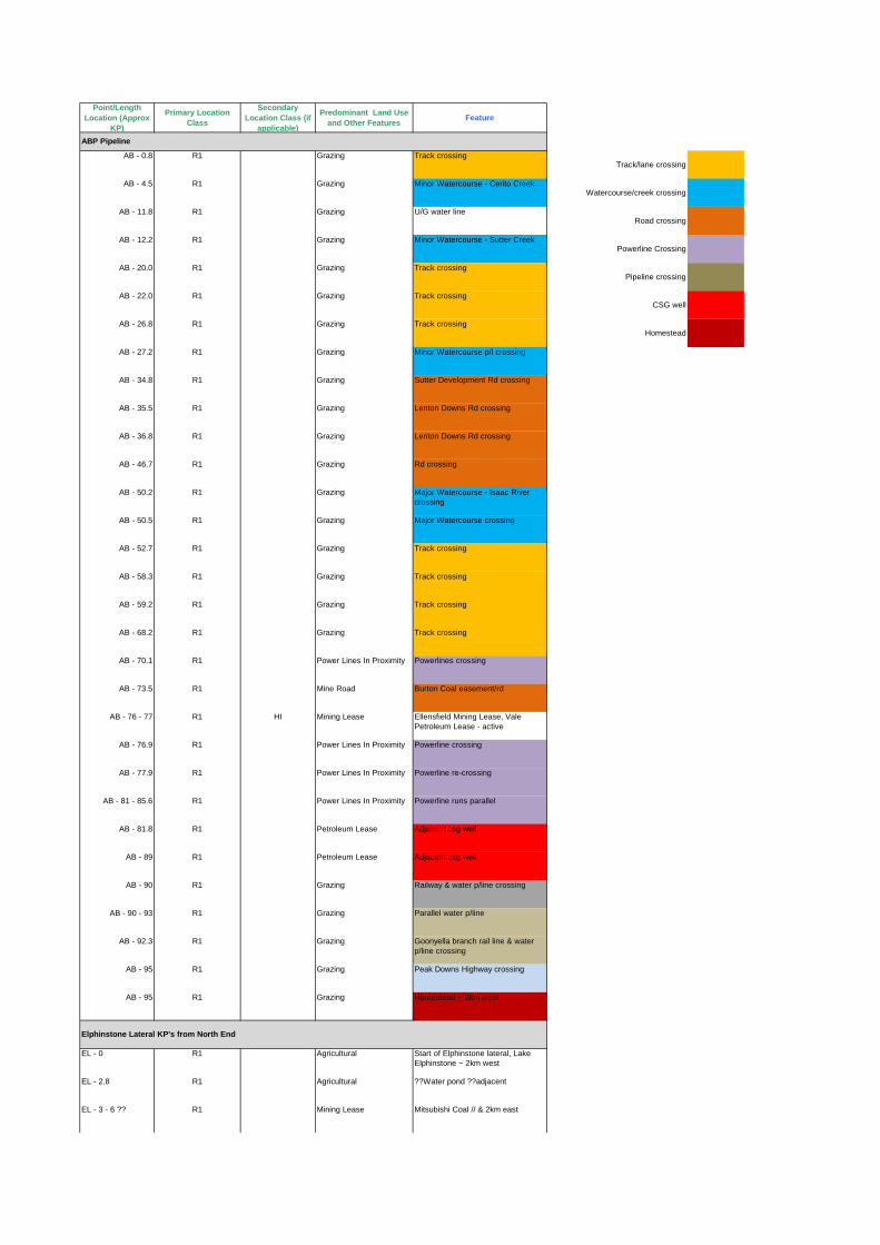
Point/LengthLocation (Approx
KP)
Primary LocationClass
SecondaryLocation Class (if
applicable)
Predominant Land Useand Other Features
Feature
AB - 0.8 R1 Grazing Track crossingTrack/lane crossing
AB - 4.5 R1 Grazing Minor Watercourse - Cerito CreekWatercourse/creek crossing
AB - 11.8 R1 Grazing U/G water lineRoad crossing
AB - 12.2 R1 Grazing Minor Watercourse - Sutter CreekPowerline Crossing
AB - 20.0 R1 Grazing Track crossingPipeline crossing
AB - 22.0 R1 Grazing Track crossingCSG well
AB - 26.8 R1 Grazing Track crossingHomestead
AB - 27.2 R1 Grazing Minor Watercourse p/l crossing
AB - 34.8 R1 Grazing Sutter Development Rd crossing
AB - 35.5 R1 Grazing Lenton Downs Rd crossing
AB - 36.8 R1 Grazing Lenton Downs Rd crossing
AB - 46.7 R1 Grazing Rd crossing
AB - 50.2 R1 Grazing Major Watercourse - Isaac Rivercrossing
AB - 50.5 R1 Grazing Major Watercourse crossing
AB - 52.7 R1 Grazing Track crossing
AB - 58.3 R1 Grazing Track crossing
AB - 59.2 R1 Grazing Track crossing
AB - 68.2 R1 Grazing Track crossing
AB - 70.1 R1 Power Lines In Proximity Powerlines crossing
AB - 73.5 R1 Mine Road Burton Coal easement/rd
AB - 76 - 77 R1 HI Mining Lease Ellensfield Mining Lease, ValePetroleum Lease - active
AB - 76.9 R1 Power Lines In Proximity Powerline crossing
AB - 77.9 R1 Power Lines In Proximity Powerline re-crossing
AB - 81 - 85.6 R1 Power Lines In Proximity Powerline runs parallel
AB - 81.8 R1 Petroleum Lease Adjacent csg well
AB - 89 R1 Petroleum Lease Adjacent csg well
AB - 90 R1 Grazing Railway & water p/line crossing
AB - 90 - 93 R1 Grazing Parallel water p/line
AB - 92.3 R1 Grazing Goonyella branch rail line & waterp/line crossing
AB - 95 R1 Grazing Peak Downs Highway crossing
AB - 95 R1 Grazing Homestead ~ 2km west
EL - 0 R1 Agricultural Start of Elphinstone lateral, LakeElphinstone ~ 2km west
EL - 2.8 R1 Agricultural ??Water pond ??adjacent
EL - 3 - 6 ?? R1 Mining Lease Mitsubishi Coal // & 2km east
Elphinstone Lateral KP's from North End
ABP Pipeline

EL - 13 R1 Power Lines In Proximity Powerline Crossing
EL - 14.9 R1 Agricultural unnamed road reserve crossing
EL - 19.9 R1 Agricultural Carborough Range - unnamed roadreserve
EL - 25.2 R1 Agricultural Track crossing
EL - 25.7 R1 Agricultural Track crossing
EL - 28.1 R1 Agricultural Track crossing
EL - 28.3 R1 Agricultural Track end?
EL - 30.2 R1 Agricultural adjacent SW7 csg wellsite (<100m)
EL - 35.2 R1 Agricultural Track crossing
EL - 35.8 R1 Agricultural Track crossing
EL - 45 - 46 R1 Mining Lease parellel to Coppabella m/lease(~1km east)
EL - 46.7 R1 Agricultural Track crossing
EL - 46.9 R1 Other Pipeline in Vicinity U/G Water line
EL - 47 R1 Industrial Railway - Goonyella branch
EL - 47.7 R1 Power Lines In Proximity Powerline crossing
EL - 47.8 - 48.5 R1 Power Lines In Proximity Parallel Powerlines < 100m
EL - 48.5 - 52 R1 Grazing Petroleum lease to end of lateral
EL - 52 R1 Grazing Joins ABP mainline
AB - 95-97 Possible cultivation over the pipeline
AB - 95.9 R1 Grazing Elphinstone Lateral
AB - 99.3 R1 Grazing Easement crossing
AB - 100 - 101 R1 Other Pipeline in Vicinity Coppabella p/line. P/line crossesroad easement twice
AB - 101 R1 Mining Lease Norwich Park branch rail line
AB - 101.9 R1 Mining Lease Rd crossing
AB - 103 - 105 R1 Grazing Large road easement runs parallel
AB - 107 R1 Grazing Road reserve crossing
AB - 105.1 R1 Grazing Minor Watercourse - North Creekcrossing
AB - 106.8 - 107 R1 Grazing Rd reserve crossing
AB - 109.3 R1 Grazing Annandale rd crossing
AB - 111.5 R1 Grazing Olive Downs B Haul road crossing?
AB - 111.8 R1 Grazing Track crossing
AB - 112 R1 Grazing Annandale rd crossing
AB - 119 R1 Grazing Annandale rd crossing
AB - 122.3 R1 Grazing Track crossing
AB - 125.3 R1 Grazing Track crossing
AB - 126 R1 Grazing Track crossing

AB - 127 R1 Grazing Track crossing
AB - 129.1 R1 Grazing Track crossing
AB - 129.8 R1 Grazing Track crossing
AB - 132 R1 Grazing ??east 400m??
AB - 132.5 R1 Grazing Track crossing
AB - 133 R1 Grazing ??east???
AB - 137 R1 Grazing ??east???
AB - 137 R1 Grazing Annandale rd crossing
SL - 0 R1 Agricultural Start of Dysaht lateral
SL - 0.5 R1 Other Pipeline in Vicinity CQP p/l crossing
SL - 3.1 - 6.7 R1 Mining Lease Mining Development Licence
SL - 7.5 R1 Agricultural Track crossing
SL - 13 - 14 R1 Grazing lateral runs along track
SL - 16 R1 Grazing Track crossing
SL - 18.8 R1 Grazing Major Watercourse - Isaac Rivercrossing
SL - 19.7 R1 Grazing Track crossing
SL - 25.8 R1 Grazing joins ABP main line
AB - 137.2 R1 Grazing Saraji Lateral
AB - 142 - 152 R1 Grazing Fitzroy Development Rd runsparallel
AB - 145.2 R1 Grazing Track crossing
AB - 151.6 R1 Grazing Track crossing
AB - 151 - 152 R1 Grazing ?? What't this??
AB - 157 R1 Grazing Track crossing
AB - 159.2 R1 Grazing Track crossing
AB - 161.2 R1 Grazing Track crossing
AB - 164.6 R1 Grazing Major Watercourse - Isaac River
AB - 165 R1 Grazing Homestead ~2km west
AB - 165.5 R1 Grazing Carfax rd crossing
AB - 170.2 R1 Grazing Track crossing
AB - 170.3 R1 Grazing Minor Watercourse - StephensCreek crossing
DL - 0 R1 Agricultural Start of Dysaht lateral
DL - 0 - 15 R1 Agricultural On Golden Mile Road alignment
DL - 0 R1 Other Pipeline in Vicinity CQP 1km south west of Dysahtlateral start
DL - 0.3 R1 Agricultural Track start
Saraji Lateral KP's from West End
Dysaht Lateral KP's from West End

DL - 2.2 R1 Grazing Bowen Norwich Park CSG p/lease -start
DL - 3.7 R1 Grazing Track start
DL - 6 R1 Grazing CSG wellhead - on alignment
DL - 7.3 - 14.1 R1 Mining Lease Mining Development Licence
DL - 10.6 R1 Mining Lease ??? > 300m s/west???
DL - 12 R1 Mining Lease Track crossing
DL - 15.3 R1 Grazing Track crossing
DL - 16.5 R1 Grazing Track crossing
DL - 17.1 R1 Grazing Minor Watercourse - StephensCreek crossing
DL - 20.2 R1 Grazing Track crossing
DL - 20.2 - 25.7 R1 Grazing lateral runs along FitroyDevelopment Road
DL - 25.7 R1 Grazing end of Dysaht Lateral
AB - 172.7 R1 Grazing Dysaht Lateral
AB - 173 R1 Grazing Fitzroy Development Road crossing
AB - 180.5 R1 Grazing Track crossing
AB - 189.5 R1 Grazing Track crossing
AB - 193.3 R1 Grazing Track crossing
AB - 194.8 R1 Grazing Track crossing
AB - 195.5 R1 Grazing May Downs Carfax road
AB - 196 R1 Grazing Track crossing
AB - 201.5 R1 Grazing Track crossing
AB - 205.2 R1 Grazing Track crossing
AB - 205.7 R1 Grazing Track crossing
AB - 206 R2 Grazing Langley Homestead ~ 2km southwest
AB - 210.9 R1 Grazing Track crossing
AB - 211.9 R1 Grazing Track crossing
AB - 212.9 R1 Grazing Major Watercourse - Rolf Ck (IsaacRiver) crossing
AB - 228.1 R1 Grazing May Downs road crossing
AB - 234 R1 Grazing Track crossing
AB - 234.7 R1 Grazing Major Watercourse - Isaac Rivercrossing
AB - 238.5 R1 Grazing (caused a 90deg kink - non-perren??) watercourse
AB -239.7 R1 Grazing ??Similar?? Watercourse
AB - 245 R2 Grazing Clive Homestead ~ 2km north east
AB - 245.9 R1 Grazing Track crossing
AB - 253.5 R1 Power Lines In Proximity Powerline crossing
AB - 254.7 R1 Petroleum Lease Manly Access Road crossing

AB - 262.2 R1 Grazing Track crossing
AB - 263.7 R1 Grazing Tartrus Road crossing
AB - 265 - 271 R1 Other Pipeline in Vicinity AGL p/line < 1km away runningparallel
AB - 276 - 277 R1 Grazing Track parallel / crossing
AB - 271 - 278 R1 Other Pipeline in Vicinity AGL p/line 200-300m away, runningparallel
AB - 278 - 349 R1 Other Pipeline in Vicinity AGL p/line < 1km away, runningparallel
AB - 279 R1 Grazing Track crossing
AB - 280 R1 Grazing unnamed rd reserve crossing
AB - 281.5 R1 Grazing Track crossing
AB - 282.2 R1 Grazing unnamed rd reserve crossing
AB - 284.7 R1 Grazing Duaringa Apis Ck rd crossing
AB - 289.7 - 291.8 R1 Grazing Apis Ck Stud Holding rd runsparallel
AB - 293 R1 Grazing Track starts
AB - 293 - 299 R1 Grazing Track runs parallel
AB - 300.2 R1 Grazing Track crossing
AB - 301.8 R1 Grazing Track crossing
AB - 302.3 R1 Grazing Track crossing
AB - 303.3 R1 Grazing Track crossing
AB - 303.8 R1 Power Lines In Proximity Powerline crossing
AB - 304.1 R1 Other Pipeline in Vicinity AGL P/line crossing
AB - 306.5 R1 Grazing Track crossing
AB - 308.1 R1 Grazing Track crossing
AB - 310.1 R1 Other Pipeline in Vicinity AGL P/line crossing
AB - 310.1 R1 Grazing Morbank Rd crossing
AB - 311.3 R1 Grazing Morbank Rd runs parallel
AB - 316.7 R1 Grazing Genroy Marlborough Rd crossing
AB - 316.5 R1 Other Pipeline in Vicinity AGL P/line crossing
AB - 319.5 R1 Grazing Major Watercourse - Fitzroy Rivercrossing
AB - 322.2 R1 Grazing Unnamed rd reserve crossing
AB - 324 R1 Grazing Redbank Homestead 500m NE
AB - 324.4 R1 Grazing Unnamed road reserve crossign
AB - 327.8 R1 Grazing Track starts
AB - 328.3 R1 Grazing Rd reserve crossing
AB - 329.2 R1 Other Pipeline in Vicinity Marlborough Nickel's GladstoneNickel Project p/line crossing
AB - 329.2 - 407.5 R1 Other Pipeline in Vicinity Gladstone Nickel Project p/line runsapprox parallel
AB - 338 R1 Grazing Fairview Rd crossing
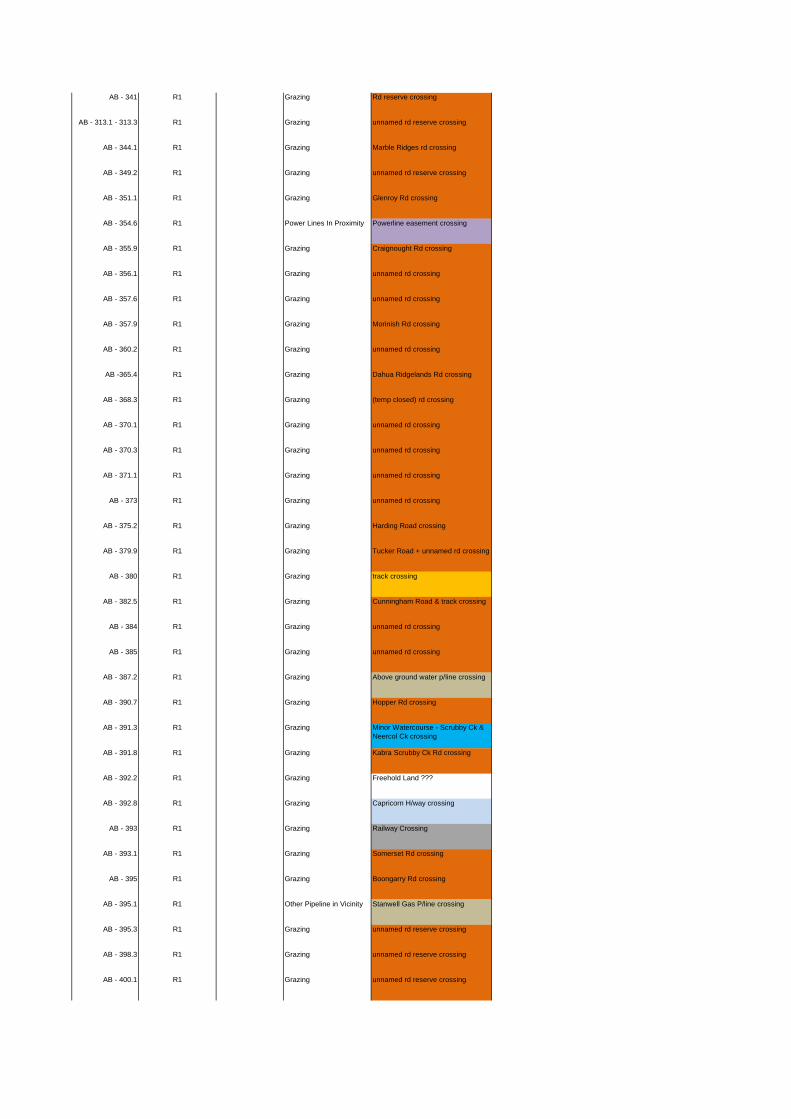
AB - 341 R1 Grazing Rd reserve crossing
AB - 313.1 - 313.3 R1 Grazing unnamed rd reserve crossing
AB - 344.1 R1 Grazing Marble Ridges rd crossing
AB - 349.2 R1 Grazing unnamed rd reserve crossing
AB - 351.1 R1 Grazing Glenroy Rd crossing
AB - 354.6 R1 Power Lines In Proximity Powerline easement crossing
AB - 355.9 R1 Grazing Craignought Rd crossing
AB - 356.1 R1 Grazing unnamed rd crossing
AB - 357.6 R1 Grazing unnamed rd crossing
AB - 357.9 R1 Grazing Morinish Rd crossing
AB - 360.2 R1 Grazing unnamed rd crossing
AB -365.4 R1 Grazing Dahua Ridgelands Rd crossing
AB - 368.3 R1 Grazing (temp closed) rd crossing
AB - 370.1 R1 Grazing unnamed rd crossing
AB - 370.3 R1 Grazing unnamed rd crossing
AB - 371.1 R1 Grazing unnamed rd crossing
AB - 373 R1 Grazing unnamed rd crossing
AB - 375.2 R1 Grazing Harding Road crossing
AB - 379.9 R1 Grazing Tucker Road + unnamed rd crossing
AB - 380 R1 Grazing track crossing
AB - 382.5 R1 Grazing Cunningham Road & track crossing
AB - 384 R1 Grazing unnamed rd crossing
AB - 385 R1 Grazing unnamed rd crossing
AB - 387.2 R1 Grazing Above ground water p/line crossing
AB - 390.7 R1 Grazing Hopper Rd crossing
AB - 391.3 R1 Grazing Minor Watercourse - Scrubby Ck &Neercol Ck crossing
AB - 391.8 R1 Grazing Kabra Scrubby Ck Rd crossing
AB - 392.2 R1 Grazing Freehold Land ???
AB - 392.8 R1 Grazing Capricorn H/way crossing
AB - 393 R1 Grazing Railway Crossing
AB - 393.1 R1 Grazing Somerset Rd crossing
AB - 395 R1 Grazing Boongarry Rd crossing
AB - 395.1 R1 Other Pipeline in Vicinity Stanwell Gas P/line crossing
AB - 395.3 R1 Grazing unnamed rd reserve crossing
AB - 398.3 R1 Grazing unnamed rd reserve crossing
AB - 400.1 R1 Grazing unnamed rd reserve crossing
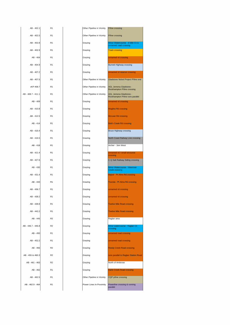
AB - 402.1 R1 Other Pipeline in Vicinity P/line crossing
AB - 402.5 R1 Other Pipeline in Vicinity P/line crossing
AB - 402.8 R1 Grazing Minor Watercourse - 4 Mile Ck &unnamed road crossing
AB - 402.9 R1 Grazing Track crossing
AB - 404 R1 Grazing unnamed rd crossing
AB - 404.9 R1 Grazing Burnett Highway crossing
AB - 407.2 R1 Grazing unnamed rd reserve crossing
AB - 407.5 R1 Other Pipeline in Vicinity Gladstone Nickel Project P/line end
vKP 408.7 R1 Other Pipeline in Vicinity AGL Jemena Gladstone -Rockhampton P/line crossing
AB - 408.7 - 411.1 R1 Other Pipeline in Vicinity AGL Jemena Gladstone -Rockhampton P/line runs parallel
AB - 409 R1 Grazing unnamed rd crossing
AB - 410.8 R1 Grazing Mogilno Rd crossing
AB - 412.5 R1 Grazing McLean Rd crossing
AB - 414 R1 Grazing Bob's Creek Rd crossing
AB - 416.4 R1 Grazing Bruce Highway crossing
AB - 416.5 R1 Grazing North Coast Railway Line crossing
AB - 418 R1 Grazing Archer - 1km West
AB - 421.4 R1 Grazing unnamed rd / small w/coursecrossing
AB - 427.6 R1 Grazing C Q Salt Railway Siding crossing
AB - 430 R1 Grazing Minor Watercourse - InkermanCreek crossing
AB - 431.4 R1 Grazing Bajool - Pt Alma Rd crossing
AB - 433 R1 Grazing Toonda - Pt Alma Rd crossing
AB - 436.7 R1 Grazing unnamed rd crossing
AB - 438.2 R1 Grazing unnamed rd crossing
AB - 438.8 R1 Grazing Twelve Mile Road crossing
AB - 442.2 R1 Grazing Twelve Mile Road crossing
AB - 445 R2 Grazing Raglan area
AB - 446.7 - 446.8 R2 Grazing Minor watercourse - Raglan Ckcrossing
AB - 450 R1 Grazing unnamed road crossing
AB - 452.2 R1 Grazing unnamed road crossing
AB - 455 R2 Grazing Reedy Creek Road crossing
AB - 455 to 460.3 R2 Grazing runs parallel to Raglan Station Road
AB - 461 - 463 R2 Grazing North of Ambrose
AB - 462 R1 Grazing Darts Creek Road crossing
AB - 462.5 R1 Other Pipeline in Vicinity CQP p/line crossing
AB - 462.9 - 464 R1 Power Lines In Proximity Powerline crossing & runningparallel

AB - 465.5 R1 Grazing Popenia Road crossing
AB - 467 R2 Grazing start of Mt Larcom area
AB - 467.5 R2 Grazing Gostevsky Road crossing
AB - 469.7 R2 Grazing Narrows Road crossing
AB - 469.9 R2 Industrial Other Pipeline in Vicinity CQP p/line crossing
AB - 470.3 R2 Industrial Other Pipeline in Vicinity Santos GLNG P/line crossing
AB - 470.4 R2 Industrial Other Pipeline in Vicinity QCLNG P/line crossing
AB - 470.4 R2 Industrial Other Pipeline in Vicinity APacLNG P/line crossing
AB - 471 - 476 R2 Industrial Other Pipeline in Vicinity
AB - 471 R2 Industrial Other Pipeline in Vicinity Railway crossing
AB - 476.1 R2 Industrial Other Pipeline in Vicinity CQP P/line crossing
AB - 478 R2 Industrial Other Pipeline in Vicinity end of p/line
AB - 418 - end R2 Industrial Petroleum Lease SGIC Corridor
AB - 469.5 - end R2 Industrial Petroleum Lease GSDA Corridor
AB - 329- 407.9 R2 Industrial Petroleum Lease Marlborough Nickel Corridor
08-GHD-02-0006 - Arrow Energy Major Pipelines - Initial Safety Management Study
Appendix G
General Action Items Closed Out

41/24306/426868
04 October 2011
To Ian Grimmer
Copy to Iain Burgess
From Rubi Turna Tel (07) 3316 3271
Subject ABP Initial SMS General Actions Closed Out Job no. 41/24306
As per Table 6 in Section 7 of the ABP Initial SMS Report (08-ABP-02-0006 Rev C), the following
general actions assigned to GHD have been closed out.
Item # General Action Comment Status
1 Railway depth of cover -
measured from bottom of ballast?
Railway depth of cover is measured from
bottom of rail not ballast as per API 1102.
Completed
2 Specify minor and majorwatercourse crossings in the
pipeline walk through.
Refer to Appendix F of ABP Initial SMSReport (08-ABP-02-0006 Rev C).
Completed
22 Calculate the overlap of
measurement lengths in T1 andSensitive location class zones.
T1 location class runs from AB 446 – 469
km. The S location class is located at AB465.
For a DN 800 pipe size the measurementlength is 1.1 km which gives an overlapdistance of 463.9 to 466.1 km.
For a DN 1050 pipe size themeasurement length is 1.25 km whichgives an overlap distance of 463.75 to
466.25 km.
Completed
24 Investigate operating pressures
for slurry pipelines to furtherconsider threats posed to
adjacent gas pipelines.
The Marlborough Nickel slurry pipeline is
classified as high pressure howeverunable to ascertain exact pressure.
Unable to
ascertain

241/24306/426868
25 GHD to determine frequency of
DCVG surveys for detecting
latent defects from third partyimpact.
Frequency of DCVG surveys are based
on the result of CPU test readings and at
the discretion of the operator. In somecases, DCVG surveys on similar sizepipelines have been conducted on a
yearly basis.
Completed
27 Try to find photo of lightning
strike.
Occurred on the Amadeus Basin
Pipeline.
Unable to
locate
Regards
Rubi TurnaPipeline Engineer

08-GHD-02-0006 - Arrow Energy Major Pipelines - Initial Safety Management Study
GHD 2011
201 Charlotte Street Brisbane QLD 4000
GPO Box 668 Brisbane QLD 4001
T: (07) 3316 3000 F: (07) 3316 3333 E: [email protected]