report from rf session (1:30-5:40 pm, 3/30/2004) h. haseroth and derun li center for beam physics...
Post on 21-Dec-2015
213 views
TRANSCRIPT

Report from RF Session Report from RF Session (1:30-5:40 PM, 3/30/2004)(1:30-5:40 PM, 3/30/2004)
H. Haseroth and Derun Li
Center for Beam PhysicsLawrence Berkeley National Laboratory
MICE Collaboration Meeting at CERNMarch 31, 2004

MICE Collaboration Mgt in CERNMarch 31, 2004
Report from RF Session Derun Li
Center for Beam Physics LBNL Page 2
MICE RF
• Eight 201.25 MHz cavities (4-cavity per module) with curved Be windows (21-cm radius and 0.38 mm thick)– Cavity body, ports, vacuum, probe, cooling channel– RF windows + couplers– Curved Be windows
• 8 MW (or more?) peak RF power system + distribution system – Low level RF control (RAL)– Driver amplifiers, amplifiers and PSs– Distribution system (rigid coaxial transmission lines,
pressurization with dry N2 or SF6), hybrids vs circulators, phase shifters, …

MICE Collaboration Mgt in CERNMarch 31, 2004
Report from RF Session Derun Li
Center for Beam Physics LBNL Page 3
Agenda
Status of the 200 MHz cavity (D. Li) Status of power amplifiers and drivers at RAL (P. Drumm) 201 MHz cavity fabrication (R. Rimmer) Status of power amplifiers and drivers at CERN
(H. Haseroth) Curved Be window designs (S. Yang) 201 MHz RF system for MICE (hybrids) (Al Moretti) Controls (Blondel’s table) Layout Layout Discussions

MICE RF - Power sources and distribution system
(PD, HH and AM’s presentations)
RF group at the Daresbury SRS
• Mike Dykes (group leader)
• Andy Moss (senior RF Engineer)
• plus two more
• MD & AM are here…

MICE Collaboration Mgt in CERNMarch 31, 2004
Report from RF Session Derun Li
Center for Beam Physics LBNL Page 5
Baseline ?
4 MW Transmitter2 MW Transmitter 2 MW Transmitter
Master Oscillator
201 MHz Cavity Module 201 MHz Cavity Module
3 db Hybrid & Load
Matched Splitter
Circulator & Load

MICE Collaboration Mgt in CERNMarch 31, 2004
Report from RF Session Derun Li
Center for Beam Physics LBNL Page 6
Split – Circulator - RF Scheme
R.F.LEVEL
R.F. LEVEL SUM
CIRCULATOR
CIRCULATOR
PHASE
SHIFTER
R.F. SOURCE33kV H.T. 18kV H.T.
TUNE ERROR
TUNE ERROR
CAVITY PHASE
PHASE DET
PHASE DET
TH116
2.5MW
4616
250kW
SOLID STATE DRIVER
R.F. LEVEL
AND
PHASE
CONTROL
CAVITY PHASE
F R
F R
70db COUPLER
70db COUPLER
MATCHED
POWER
SPLITTER
CAVITY
CAVITY
LOAD
LOAD

MICE Collaboration Mgt in CERNMarch 31, 2004
Report from RF Session Derun Li
Center for Beam Physics LBNL Page 7
RF Power Baseline Design
8 MW peak RF power:
• RF Power Design driven by cost issues (no funds for a new system)– Optimal – one amplifier per cavity
• Two amplifiers from LBNL = 4 MW total
• One or two amplifiers from CERN = 4 MW total– If 1 amplifier – needs a bigger drive?– Possibly more coaxial components from CERN
• Spare TH116 Tubes from ISIS
• Low level RF and RF layout (not covered this time)
MICE Collaboration Mgt in CERNMarch 31, 2004
Report from RF Session Derun Li
Center for Beam Physics LBNL Page 8
RF Power Amplifiers available at CERN/PS
There is one more amplifier from Linac1: It got modified to 88 MHz (foreseen for tests with our 88 MHz cavity for the cooling channel in the CERN scenario. 2 MW(FTH triode tube)driver (LHC type, modified) available If amplifier is modified: 4 MW achievable, but driver must be pushed
Of course: to modify to 88 MHz and modify again is not too attractive…

MICE Collaboration Mgt in CERNMarch 31, 2004
Report from RF Session Derun Li
Center for Beam Physics LBNL Page 9
RF driver Amplifiers available at CERN/PS
200 MHz: 3 amplifiers 350 (400) kW, one available now, 2 more in the near future(with Siemens tube no longer built). Still several spare tubes in stock. One tube good for up to 15 000 h in300s, 1 Hz, not full power regime.
Needs power supply for 40 kCHF. Switching via cathode (5 kCHF).
GSI (Hutter) says that change to a tube which is still available is not a major issue…
MICE Collaboration Mgt in CERNMarch 31, 2004
Report from RF Session Derun Li
Center for Beam Physics LBNL Page 10
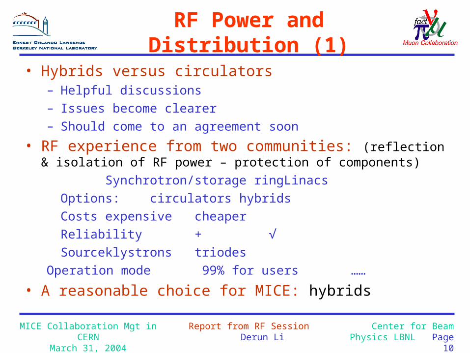
RF Power and Distribution (1)
• Hybrids versus circulators– Helpful discussions – Issues become clearer – Should come to an agreement soon
• RF experience from two communities: (reflection & isolation of RF power – protection of components)
Synchrotron/storage ring LinacsOptions: circulators hybridsCosts expensive cheaperReliability + √Source klystrons triodes
Operation mode 99% for users ……
• A reasonable choice for MICE: hybrids

MICE Collaboration Mgt in CERNMarch 31, 2004
Report from RF Session Derun Li
Center for Beam Physics LBNL Page 11
RF Power and Distribution (2)
• Rigid 50 Ω, 4 1/16”- 9 3/16” coaxial transmission lines with pressurized gas – SF6 gives higher P/P’ ratio, but have safety issues – Dry N2 at ~ 2 atm absolute pressure
Cost of the Components (by AM): The cost of components assuming 25 feet of 9 3/16 straight and 4 EL-Bows and 25 feet of straight 6 1/8 and 4 EL-Bows
25 feet ST 9 3/16 line $5,60025 feet ST 6 1/8 line $3,7004 EL-Bows 9 3/16 $10,3004 EL-Bows 6 1/8 $6,800The first Hybrid $8,000Second Hybrid $4,500First Hybrid Load $2,022Second Hybrid Load $1,400Mech. Phase Shifter $4,300Several directional C $4,500Total Cost = $49,722

MICE Collaboration Mgt in CERNMarch 31, 2004
Report from RF Session Derun Li
Center for Beam Physics LBNL Page 12
Main power consumption and cooling requirements for 1 Hz and 1 ms pulse length:
2 4 MW rf require about 2 10 MW supply.
Total: 20 kW with 0.1% duty cycle.
Filament needs 2 360 A and 15 V = 2 5 kW = 10 kW.
Total for final amplifiers: 30 kW
Total for driver amplifiers: 10 kW
Grand Total for rf amplifiers: 40 kW
50 % of power estimated to go into the cooling water: requires about 20 l/min water.
The rest goes into the air…
Available coax lines (9 inch?): 10 cubes for making 90 bends.
Power Consumption (HH)

The 201.25 MHz Cavity with Be windows
- Prototype(DL,RR,SY)

MICE Collaboration Mgt in CERNMarch 31, 2004
Report from RF Session Derun Li
Center for Beam Physics LBNL Page 14
Status
The 201 MHz cavity design and fabrication go smoothly Spun shells ready for machining after e-beam welding Nose pieces, stiffener rings and fixture were made Support structures for the equator welding Ready for equator welding tomorrow at JLab
Engineering design (details) is still continuing Ports (succeeded in extruding tests and qualified the
techniques) Couplers (done with conceptual design) Tuners
Significant progress on curved window design and fabrication– Succeeded in making S.S. curved windows, curved Be windows
for 805 MHz cavity by Brush-Wellman company– Ready for 201 MHz cavity windows
The cavity will be ready for test at MTA, Fermilab this fall !

MICE Collaboration Mgt in CERNMarch 31, 2004
Report from RF Session Derun Li
Center for Beam Physics LBNL Page 15
The Cavity Profile update
De-mountable Pre-curved Be windows to terminate RF fields at the iris
2o tilt angle
Spherical section at the equator to ease addition of ports (± ~ 6o)Elliptical-like (two circles) nose to reduce peak surface field
6-mm Cu sheet allows for uses ofspinning technique and mechanical tuners
Stiffener ring

MICE Collaboration Mgt in CERNMarch 31, 2004
Report from RF Session Derun Li
Center for Beam Physics LBNL Page 16
The Cavity Parameters
The cavity design parameters The cavity design parameters – Frequency: 201.25 MHzFrequency: 201.25 MHz– ββ = 0.87 = 0.87– Shunt impedance (VShunt impedance (VTT
22/P): ~ 22 MΩ/m/P): ~ 22 MΩ/m– Quality factor (QQuality factor (Q00): ~ 53,000): ~ 53,000– Curved Be window radius and thickness: 21-cm and 0.38-Curved Be window radius and thickness: 21-cm and 0.38-
mmmm
Nominal parameters for cooling channels in a muon collider or a neutrino factory and MICE– 16+/8 MV/m peak accelerating field– Peak input RF power ~ 4.6/1 MW per cavity (85% of Q0, 3τ
filling)– Average power dissipation per cavity ~ 8.4/1 kW – Average power dissipation per Be window ~ 100/12 watts

MICE Collaboration Mgt in CERNMarch 31, 2004
Report from RF Session Derun Li
Center for Beam Physics LBNL Page 17
Recent progress for the welding
fmeasured = 200.88 MHz

MICE Collaboration Mgt in CERNMarch 31, 2004
Report from RF Session Derun Li
Center for Beam Physics LBNL Page 18
Ready For Equator Welding

MICE Collaboration Mgt in CERNMarch 31, 2004
Report from RF Session Derun Li
Center for Beam Physics LBNL Page 19
Extruding tests at JLabExtruding tests at JLab

MICE Collaboration Mgt in CERNMarch 31, 2004
Report from RF Session Derun Li
Center for Beam Physics LBNL Page 20
RF Coupler

Curved Be windows

MICE Collaboration Mgt in CERNMarch 31, 2004
Report from RF Session Derun Li
Center for Beam Physics LBNL Page 22
Evolution of the pre-curved window
Earlier window geometry:
Concave radius > convex radius
Intersecting point
Concave radius R = 500mm
Convex radius R=230.8mm
Current window geometry
Concave radius < convex radius
770 mm
Intersecting point
Convex radius = 498.11 mm
Concave radius= 300 mm

MICE Collaboration Mgt in CERNMarch 31, 2004
Report from RF Session Derun Li
Center for Beam Physics LBNL Page 23
Curved window thickness: 0.38 mm(100 C temperature gradient)
Stress results
Max stress 177 MPa
Max stress 170 MPa
Displacement:
3-D model
Max bow 2.1 mm
2-D model
Max bow 2.25mm

MICE Collaboration Mgt in CERNMarch 31, 2004
Report from RF Session Derun Li
Center for Beam Physics LBNL Page 24
Analysis on the prototype window for 805 MHz cavity
The new geometry – 16cm diameter window

MICE Collaboration Mgt in CERNMarch 31, 2004
Report from RF Session Derun Li
Center for Beam Physics LBNL Page 25
Curved Be windows by BWM
Two curved Be windows for 805 MHz cavity: 0.254 mm thick and 16-cm diameterPre-formed the Be foils first at high temperature, brazed copper frames afterwards.The windows will be Ti nitrided at LBNL for high power test at MTA, Fermilab.
MICE Collaboration Mgt in CERNMarch 31, 2004
Report from RF Session Derun Li
Center for Beam Physics LBNL Page 26
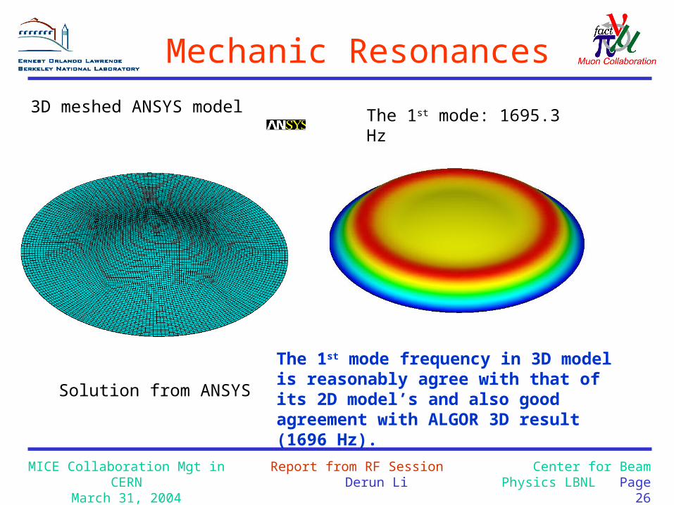
The 1st mode frequency in 3D model is reasonably agree with that of its 2D model’s and also good agreement with ALGOR 3D result (1696 Hz).
Solution from ANSYS
3D meshed ANSYS model The 1st mode: 1695.3 Hz
Mechanic Resonances

MICE Collaboration Mgt in CERNMarch 31, 2004
Report from RF Session Derun Li
Center for Beam Physics LBNL Page 27
The 9th mode: 4560 Hz
Solution from ANSYS
The 2nd and 3rd mode: 2055 Hz The 4rd and 5th mode: 3494 The 6th mode: 3754 Hz
The 7th mode: 3768 Hz
The 8th mode: 4544 HzThe 10th mode: 4866 Hz
Higher Mechanic Resonance Modes
Controls

MICE Collaboration Mgt in CERNMarch 31, 2004
Report from RF Session Derun Li
Center for Beam Physics LBNL Page 29
Discussions on Blondel’s table
∆E: A few times 10-3 of tolerance for RF voltage and phase
– Voltage stability of 10-3 is very difficult (impossible)– Phase stability: 0.5 degree – Measurement on beam
Do best to keep the voltage as stable as possible

MICE Collaboration Mgt in CERNMarch 31, 2004
Report from RF Session Derun Li
Center for Beam Physics LBNL Page 30
Summary
• 8 MW peak RF power sources have been identified, need to see actions (plans) on refurbishing and conditioning various components soon
• RF distribution system: hybrids versus circulators – Should reach an agreement for MICE soon
• Cavity prototype – Equator welding tomorrow (April 1, 2004)– Ready for ordering curved 201 MHz Be windows– Ready for high power test at MTA, Fermilab this fall
• Controls