report of geotechnical exploration and...
TRANSCRIPT

CONSULTANTS GEOTECHNICAL MATERIALS ENVIRONMENTAL FORENSICS
www.amengtest.com
REPORT OF GEOTECHNICAL EXPLORATION AND REVIEW PROPOSED MIDLAND WATER SYSTEM
UPGRADE MIDLAND, SOUTH DAKOTA
AET No. 17-02715
Date:
August 30, 2016 Prepared for: Town of Midland PO Box 232 Midland, South Dakota 57552
1745 Samco Road | Rapid City, SD 57702 Phone (605) 388-0029 | Toll Free (800) 972-6364 | Fax (605) 388-0064 | www.amengtest.com | AA/EEO
This document shall not be reproduced, except in full, without written approval from American Engineering Testing, Inc.
August 30, 2016 Town of Midland PO Box 232 Midland, South Dakota 57552 Attn: Mr. Jared Fosheim [email protected] RE: Geotechnical Exploration and Review Proposed Midland Water System Upgrade Midland, South Dakota Report No.17-02715 Dear Jared: American Engineering Testing, Inc. (AET) is pleased to present the results of our subsurface exploration program and geotechnical engineering review for the proposed water system upgrade to be constructed in Midland, South Dakota. These services were performed according to our proposal to Banner Associates dated June 28, 2016 and your authorization to proceed. We are submitting one electronic copy of the report to you, and a copy to Mr. Dave LaFrance P.E. of Banner Associates. Within the limitations of scope, budget, and schedule, our services have been conducted according to generally accepted geotechnical engineering practices at this time and location. Other than this, no warranty, either expressed or implied, is intended. Important information regarding risk management and proper use of this report is given in the Appendix entitled “Geotechnical Report Limitations and Guidelines for Use”. Please contact me if you have any questions about the report. I can also be contacted for arranging construction observation and testing services during the construction phase of this project. Sincerely, American Engineering Testing, Inc. Kristen R. Yates, P.E. Geotechnical Engineer Phone: (605) 388-0029 Fax: (605) 388-0064 [email protected] Page i
CONSULTANTS · GEOTECHNICAL · MATERIALS · ENVIRONMENTAL
A AMERICANENGINEERINGTESTING, INC.

Report of Geotechnical Exploration and Review Proposed Midland Water System AMERICAN August 30, 2016 ENGINEERING Report No. 17-02715 TESTING, INC.
Page ii Copyright 2016 American Engineering Testing, Inc. All Rights Reserved
Unauthorized use or copying of this document is strictly prohibited by anyone other than the client for the specific project.
SIGNATURE PAGE
Prepared for: Prepared by: Town of Midland American Engineering Testing, Inc. PO Box 232 1745 Samco Road Midland, South Dakota 57552 Rapid City, South Dakota 57702 (605) 388-0029 / www.amengtest.com Attn: Mr. Jared Fosheim [email protected] Report Authored By: Review By: Kristen R. Yates, PE Robert Temme, P.E. Geotechnical Engineer Vice President Western Region

Report of Geotechnical Exploration and Review Proposed Midland Water System AMERICAN August 30, 2016 ENGINEERING Report No. 17-02715 TESTING, INC.
TABLE OF CONTENTS Transmittal Letter ........................................................................................................................................... i Signature Page .............................................................................................................................................. ii 1.0 INTRODUCTION .................................................................................................................... 1 2.0 SCOPE OF SERVICES ............................................................................................................ 1 3.0 PROJECT INFORMATION ..................................................................................................... 1 4.0 SUBSURFACE EXPLORATION AND TESTING ................................................................ 2
4.1 Field Exploration Program .................................................................................................... 2 4.2 Laboratory Testing ................................................................................................................ 2
5.0 SITE CONDITIONS ................................................................................................................. 3 5.1 Surface Observations ............................................................................................................. 3 5.2 Subsurface Soils/Geology ....................................................................................................... 3 5.3 Groundwater .......................................................................................................................... 4
6.0 RECOMMENDATIONS .......................................................................................................... 4 6.1 Discussion .............................................................................................................................. 4 6.2 Water Tank Site Preparation ................................................................................................... 4 6.3 Tank Foundation Recommendations ..................................................................................... 5 6.4 Trench Excavation/Backfill ................................................................................................... 6 6.5 Corrosion Potential ................................................................................................................ 7
7.0 CONSTRUCTION CONSIDERATIONS ................................................................................ 8 7.1 Potential Difficulties .............................................................................................................. 8 7.2 Runoff Water in Excavation .................................................................................................. 8 7.3 Disturbance of Soils............................................................................................................... 9 7.4 Excavation Backsloping ........................................................................................................ 9 7.5 Observation and Testing ........................................................................................................ 9
8.0 LIMITATIONS ......................................................................................................................... 9 STANDARD SHEETS - Freezing Weather Effects on Building Construction Excavation and Refilling for Structural Support APPENDIX A – Geotechnical Field Exploration and Testing Unified Soil Classification System Site Location Map Boring Location Map Subsurface Boring Logs Swell/Consolidation Results Moisture-Density Relationship APPENDIX B – Geotechnical Report Limitations and Guidelines for Use
Page iii

Report of Geotechnical Exploration and Review Proposed Midland Water System AMERICAN August 30, 2016 ENGINEERING Report No. 17-02715 TESTING, INC.
PAGE 1 OF 9
1.0 INTRODUCTION
We understand a new water storage tank and new water lines are to be constructed in Midland,
South Dakota. Refer to the Site Vicinity Map in Appendix A of this report. To assist with the
planning and design, you have authorized American Engineering Testing, Inc. (AET) to conduct
a subsurface exploration program at the site, conduct soil laboratory testing, and perform a
geotechnical engineering review for the project. This report presents the results of the above
services, and provides our engineering recommendations based on this data.
2.0 SCOPE OF SERVICES
AET's services were performed in general accordance with our proposal dated June 28, 2016.
The authorized scope consists of the following:
Nine (9) standard penetration test (SPT) borings. One (1) SPT boring to a depth of approximately 25 feet south of the existing water storage tank location, and eight (8) SPT borings to depths of 10 feet along the alignment for the proposed water line.
Soil laboratory testing.
Geotechnical engineering analysis based on the gained data and preparation of this report.
These services are intended for geotechnical purposes only. The scope is not intended to explore
for the presence or extent of environmental contamination.
3.0 PROJECT INFORMATION
Based on the information provided by Banner Associates, we understand the project will include
a new water storage tank as well as water lines along Stanley Street, Pierre Street, and
Northwestern Avenue. We estimate approximately 2,900 lineal feet of new 6-inch diameter
water line between Phase I and Phase 2 of the project. We understand Phase I will include
350feet of water line placement on Stanley Street between Elm and Ash Streets; and 750 feet of
water line placement on Pierre Street between Ash and Russel Avenue. Phase 2 of the project
will include installation of approximately 1,800 feet of new water line along Northwestern
Avenue between Elm and Wakapala Streets. We anticipate the depth of the water line will be
between 6 to 8 feet below existing grades.
We understand the new water storage tank will be approximately 20 feet in diameter and 23 feet
in height and will be located immediately south of the existing water tank. We estimate this tank
will hold approximately 10,000 gallons of water.

Report of Geotechnical Exploration and Review Proposed Midland Water System AMERICAN August 30, 2016 ENGINEERING Report No. 17-02715 TESTING, INC.
PAGE 2 OF 9
The previously stated information represents our understanding of the proposed construction.
This information is an integral part of our engineering review. It is important that you contact us
if there are changes from that described so that we can evaluate whether modifications to our
recommendations are appropriate.
4.0 SUBSURFACE EXPLORATION AND TESTING
4.1 Field Exploration Program
The subsurface exploration program conducted for the project consisted of one (1) SPT boring at
the approximate location of the new water tank and eight (8) SPT borings along the proposed
water line alignment. The boring drilled at the tank site was taken to a depth of 25 feet below
grade. The borings along the water line alignment were drilled to approximately 10 feet below
grade at each location. The borings were drilled on August 15 and 16, 2016 and were located in
the field by Banner Associates personnel at the approximate locations shown on the Boring
Location Map within Appendix A. Surface elevations at the boring locations were provided by
Banner Associates.
The logs of the borings and details of the methods used appear in Appendix A. The logs contain
information concerning soil layering, soil classification, geologic description, and moisture
condition. Relative density or consistency is also noted for the natural soils, which is based on
the standard penetration resistance (N-value).
4.2 Laboratory Testing
The laboratory test program included natural moisture content, dry density, Atterberg Limits,
swell/consolidation, and moisture-density relationship (standard Proctor) tests. The results for
the natural moisture content, dry density, and Atterberg Limits tests appear in Appendix A on
the individual boring logs adjacent to the samples upon which they were performed. The
results of the swell/consolidation test and the standard Proctor are included on separate sheets
attached in Appendix A.

Report of Geotechnical Exploration and Review Proposed Midland Water System AMERICAN August 30, 2016 ENGINEERING Report No. 17-02715 TESTING, INC.
PAGE 3 OF 9
5.0 SITE CONDITIONS
5.1 Surface Observations
The water tank site is located on the northwest side of the town of Midland, west of 248th
Avenue. This site is located on a hill covered with sparse vegetation.
The new water lines will be located along existing roadways throughout the town of Midland.
Stanley Street, Pierre Street and Northwestern Avenue are east-west oriented streets and covered
with gravel. Natural grass and weeds border the roadways. Stanley Street and Pierre Street are
in residential areas, while Northwestern Avenue is in the commercial/light industrial area on the
south side of Midland. In general the region slopes down to the south and southeast towards the
Bad River located south of Northwestern Avenue.
5.2 Subsurface Soils/Geology
5.2.1 Water Tank Site (Boring B-1)
In general, the site geology within the proposed tank site consists of approximately 6-inches of fat
clay topsoil over approximately 1.5 feet of fat clay with sand and gravel over top approximately 10
feet of brown weathered fat clay shale over dark gray unweathered shale to the final depth drilled at
25 feet. The subsurface soils from 2.5 feet to the bottom of the boring are all considered hard in
consistency.
5.2.2 Water line Alignments (Borings B-2 through B-9)
The water line alignment borings encountered many different layers based on the location of the
boring. However, in general the dominant soil present was fat clay. Boring B-2 encountered
approximately 2.5 feet of fat clay over weathered shale and unweathered shale. Borings B-3 and B-
5 encountered mostly fat clay fill for the entire depth of the borings. Borings B-4, B-6, B-8, and B-
9 encountered fat clay from alluvium for the entire depth of the borings. Boring B-7 encountered a
combination of 2.5 feet of fat clay fill over fat clay alluvium to the final depth of the boring. The
consistency of the soil was mostly hard with a few areas of softer soils in the firm to very stiff range.
For detailed information on the soil layering and classification please refer to the individual
Subsurface Boring Logs located in Appendix A at the back of this report.

Report of Geotechnical Exploration and Review Proposed Midland Water System AMERICAN August 30, 2016 ENGINEERING Report No. 17-02715 TESTING, INC.
PAGE 4 OF 9
5.3 Groundwater
At the time of our field work, subsurface water was not measured in any of the nine (9) borings.
The lack of subsurface water noted at the boring locations should not be taken as an accurate
representation of the actual groundwater levels. A long period of time is generally required for
groundwater to stabilize in the soils and bedrock present at the site; this period of time is generally
not available during a typical subsurface exploration program.
6.0 RECOMMENDATIONS
6.1 Discussion
Our recommendations in the following sections are intended to minimize, to varying degrees,
movement related problems to the completed structure. Even if our recommendations are followed,
we cannot guarantee that some movement will not occur. The present state of the art is such that the
risk of movement cannot be accurately assessed. It depends on a number of uncontrolled variables
such as climatic conditions during and after construction, long term fluctuations of the groundwater
level, utility line leakage, landscaping, and other similar aspects. The risk of detrimental movement
must be assumed by the project owner.
To reduce the risk of movement of the bearing strata, good drainage must be maintained during and
after construction. For this reason we recommend that the excavations be left open a minimal
amount of time.
6.2 Water Tank Site Preparation
We recommend the existing topsoil be removed from within the construction limits at the tank site.
The topsoil may be stockpiled on-site for later reuse in landscaped areas only. The on-site natural
soils are suitable for use as over lot grading where necessary.
Based on the laboratory testing and the site observations, the site fat clay and shale soils have a
moderate swell potential at 2.2% with a corresponding swell pressure of 3,900 psf. To minimize
the potential for damaging differential and total movements to the completed structure through
moisture variations in the expansive clay soils, we recommend the site fat clay soils and shale be
removed from the tank footprint to allow for the placement of at least two (2) feet of imported
granular engineered fill below the foundation and at least four (4) feet below the tank base.

Report of Geotechnical Exploration and Review Proposed Midland Water System AMERICAN August 30, 2016 ENGINEERING Report No. 17-02715 TESTING, INC.
PAGE 5 OF 9
The areas to receive engineered fill should be scarified to an additional depth of 12-inches, the
moisture content of the scarified soils adjusted to -1 to +3% of optimum moisture content and the
soils recompacted to at least 95% of maximum standard Proctor (ASTM D 698) dry density. The
base of the excavation should be proof-rolled to verify a firm and unyielding subgrade is present,
and the geotechnical engineer, or their representative, should be allowed to observe the completed
excavations prior to placement of engineered fill.
Where engineered fill is required, we recommend the use of an imported non-expansive granular
material pre-approved by the geotechnical engineer. The granular engineered fill should be a
non-expansive material with a maximum size of 2-inches, 40-85% passing the No. 4 sieve, and
no more than 15% passing the #200 sieve with a Liquid Limit less than 25. Engineered fill
should be placed in 8-inch thick maximum loose lifts; the moisture content conditioned to within
3% of optimum moisture content and compacted to at least 95% of maximum standard Proctor
dry density.
Refer to the “Excavation and Refilling for Structural Support” and the “Freezing Weather Effects on
Building Construction” documents in the Standard Sheets section at the back of this report for
additional information.
6.3 Tank Foundation Recommendations
Based on the results of our field and laboratory data, it is our opinion that the water storage tank can
be placed on a concrete ringwall founded on spread footings as long as the recommendations
presented in this report are followed. As stated previously, we recommend the foundation be over-
excavated by at least two (2) feet and backfilled with imported granular non-expansive engineered
fill. The footing excavations should be laterally oversized at a 1H:1V ratio to accommodate the
required over-excavation. The engineered fill should be moisture conditions and placed as
described in Section 6.2 Site Preparation.
The ringwall footing should be placed at least four (4) feet below the adjacent ground surface for
frost protection. The spread footing foundation system may be designed for an allowable
bearing capacity of 2,500 psf. Provided the structure is properly constructed, the total movement
is estimated to be on the order of 1-inch with differential movements on the order of 1/2-inch.

Report of Geotechnical Exploration and Review Proposed Midland Water System AMERICAN August 30, 2016 ENGINEERING Report No. 17-02715 TESTING, INC.
PAGE 6 OF 9
Additional foundation movements could occur if water from any source infiltrates the foundation
soils; therefore, proper drainage should be provided in the final design, during construction and for
the life of the project.
We also recommend a perforated foundation drain be placed around the perimeter of the concrete
ringwall foundation. The drain should be placed at the bottom outside of the foundation
excavation. The drain systems should be wrapped with a filter fabric. The drain system should be
constructed with a slope to allow for routing water to one or more locations where it can be
removed by gravity flow.
We also recommend at least four (4) feet of imported granular non-expansive engineered fill be
placed below the base/floor of the tank. The engineered fill should be moisture conditions and
placed as described in Section 6.2 Site Preparation.
6.4 Trench Excavation/Backfill
We recommend that all topsoil and organic matter be removed along the proposed water line
alignment. The topsoil may be stockpiled for later use over the alignment of the completed main in
the road right-of-ways.
The information obtained from the boring logs indicates fat clay will be the predominant soil
type encountered along the majority of the alignment. It is our opinion the fat clay is suitable for
reuse as trench backfill. However, we recommend the moisture content of the compacted trench
backfill be within -1 to +3% of the optimum moisture content and the trench backfill be
compacted to at least 95% of maximum standard Proctor dry density. Where utility trenches
cross road alignments, we recommend the compaction requirement be increased to a minimum of
98% to reduce the potential of post construction settlement of the trench which can have an
adverse effect on roadways and pavements.
All backfill should be free of deleterious/frozen material and have a maximum aggregate size of
2-inches. Bedrock (shale) material should be processed/pulverized to reduce the nominal
fragment size to no greater than 2-inches. All backfill should be placed in loose lift thicknesses
of 8-inches or less. If hand-operated compaction equipment is used, the loose lift thickness

Report of Geotechnical Exploration and Review Proposed Midland Water System AMERICAN August 30, 2016 ENGINEERING Report No. 17-02715 TESTING, INC.
PAGE 7 OF 9
should be reduced to 4-inches or less. Compaction density tests should be performed on
alternating lifts to ensure the minimum density is maintained.
Should additional fill be required, the proposed imported backfill should be submitted to the
geotechnical engineer for approval prior to use.
If excavation faces are not retained, the excavations should maintain maximum allowable slopes in
accordance with OSHA Regulations (Standards 29 CFR), Part 1926, Subpart P, “Excavations”
(can be found on www.osha.gov). Even with the required OSHA sloping, water seepage or surface
runoff can potentially induce side slope erosion or running which could require slope maintenance.
It is our opinion the fat clay soils and weathered shale can be classified as Type B soils with
recommended slope laybacks of 1H:1V. It is our opinion the unweathered shale can be classified
as Type A soils with recommended slope laybacks of ¾ H:1V. These classifications should be
considered preliminary and should be verified in the field on a daily basis by the contractor
and/or geotechnical engineer.
Excavations deeper than 20 feet and/or in saturated soils or below the groundwater table should be
considered on an individual basis. Water levels, due to climatic conditions should be evaluated at the
time of construction. If the above trench layback recommendations are not feasible, due to space
limitations or other factors, the OSHA rules should be consulted for alternative trench stabilization
methods. Trench boxes or shoring in compliance with OSHA rules may be acceptable alternatives.
Conventional moderate to large sized construction equipment, such as tracked excavators,
should be able to make the required trench excavations along the water trench alignment.
Based on our field data, we do not anticipate that groundwater will likely be encountered in the
utility excavations. Although the contractor should be prepared to use conventional dewatering
equipment should groundwater or surface water enter the utility trench excavations.
6.5 Corrosion Potential
Three (3) field electrical resistivity tests were run along the alignment of the water line. The field
tests were run using the Wenner meter with four electrodes spaced at 10-foot intervals. Results
are indicated below:

Report of Geotechnical Exploration and Review Proposed Midland Water System AMERICAN August 30, 2016 ENGINEERING Report No. 17-02715 TESTING, INC.
PAGE 8 OF 9
Boring Spacing, ft Resistivity, ohm-cm Corrosion Potential
B-2 10 613 Severe
B-3 10 517 Severe
B-7 10 1,302 Severe
The corrosion potentials provided are based on information published in the Department of the
Army’s Technical Manual TM 5-811-7 “Electrical Design, Cathodic Protection. Based on this
information, the site soils have a severe corrosion potential towards iron and other buried metals.
If corrosion of buried metal is critical, it should be protected using a non-corrosive backfill,
wrapping, coating, sacrificial anodes, or a combination of these methods, as designed by a
qualified corrosion engineer.
7.0 CONSTRUCTION CONSIDERATIONS
7.1 Potential Difficulties
Depending on the time of year in which construction takes place, soft wet subgrade soils could be
encountered during the grading and excavation operations. If encountered, additional conditioning
of the soils may be required to obtain moisture contents which allow for firm and unyielding
subgrade and/or compaction.
Localized areas of soft wet subgrades can be remedied with additional excavation to expose firmer
soils, placement of coarse rock to provide a solid base on which to place additional fill and/or the
use of geotextiles between the soft soils and the overlying fill and/or pavement sections. The
appropriate means of subgrade stabilization should be evaluated by the geotechnical engineer at the
time of construction.
7.2 Runoff Water in Excavation
Water can be expected to collect in the excavation bottom during times of inclement weather or
snow melt. To allow observation of the excavation bottom, to reduce the potential for soil
disturbance, and to facilitate filling operations, we recommend water be removed from within the
excavation during construction. Based on the soils encountered, we anticipate the groundwater
can be handled with conventional sump pumping.

Report of Geotechnical Exploration and Review Proposed Midland Water System AMERICAN August 30, 2016 ENGINEERING Report No. 17-02715 TESTING, INC.
PAGE 9 OF 9
7.3 Disturbance of Soils
The on-site soils can become disturbed under construction traffic, especially if the soils are wet.
If soils become disturbed, they should be subcut to the underlying undisturbed soils. The subcut
soils can then be dried and recompacted back into place, or they should be removed and replaced
with drier imported fill.
7.4 Excavation Backsloping
If excavation faces are not retained, the excavations should maintain maximum allowable slopes in
accordance with OSHA Regulations (Standards 29 CFR), Part 1926, Subpart P, “Excavations”
(can be found on www.osha.gov). Even with the required OSHA sloping, water seepage or surface
runoff can potentially induce sideslope erosion or running which could require slope maintenance.
7.5 Observation and Testing
The recommendations in this report are based on the subsurface conditions found at our test boring
locations. Since the soil conditions can be expected to vary away from the soil boring locations, we
recommend on-site observation by a geotechnical engineer/technician during construction to
evaluate these potential changes. Soil density testing should also be performed on new fill placed in
order to document that project specifications for compaction have been satisfied.
8.0 LIMITATIONS
Within the limitations of scope, budget, and schedule, our services have been conducted
according to generally accepted geotechnical engineering practices at this time and location.
Other than this, no warranty, either expressed or implied, is intended. Important information
regarding risk management and proper use of this report is given in Appendix B entitled
“Geotechnical Report Limitations and Guidelines for Use”.

Report of Geotechnical Exploration and Review Proposed Midland Water System AMERICAN August 30, 2016 ENGINEERING Report No. 17-02715 TESTING, INC.
STANDARD SHEETS

Report of Geotechnical Exploration and Review Proposed Midland Water System AMERICAN August 30, 2016 ENGINEERING Report No. 17-02715 TESTING, INC.
FREEZING WEATHER EFFECTS ON BUILDING CONSTRUCTION
GENERAL
Because water expands upon freezing and soils contain water, soils which are allowed to freeze will heave and loose density. Upon thawing, these soils will not regain their original strength and density. The extent of heave and density/strength loss depends on the soil type and moisture condition. Heave is greater in soils with higher percentages of fines (silts/clays). High silt content soils are most susceptible, due to their high capillary rise potential which can create ice lenses. Fine grained soils generally heave about 1/4" to 3/8" for each foot of frost penetration. This can translate to 1" to 2" of total frost heave. This total amount can be significantly greater if ice lensing occurs. DESIGN CONSIDERATIONS
Clayey and silty soils can be used as perimeter backfill, although the effect of their poor drainage and frost properties should be considered. Basement areas will have special drainage and lateral load requirements which are not discussed here. Frost heave may be critical in doorway areas. Stoops or sidewalks adjacent to doorways could be designed as structural slabs supported on frost footings with void spaces below. With this design, movements may then occur between the structural slab and the adjacent on-grade slabs. Non-frost susceptible granular soils (with less than 12% passing a #200 sieve) can be used below such areas. Depending on the function of surrounding areas, the granular soil layer may need a thickness transition away from the area where movement is critical. With granular soil placement over slower draining soils, subsurface drainage would be needed for the granular layer. High density extruded insulation could be used within the granular soils to reduce frost penetration, thereby reducing the granular soil thickness needed. We caution that insulation placed near the surface can increate the potential for ice glazing of the surface. The possible effects of adfreezing should be considered if clayey or silty soils are used as backfill. Adfreezing occurs when backfill adheres to rough surfaced foundation walls and lifts the wall as it freezes and heaves. This occurrence is most common with masonry block walls, unheated or poorly heated building situations and clay backfill. The potential is also increased where backfill soils are poorly compacted and become saturated. The risk of adfreezing can be decreased by placing a low friction separating layer between the wall and backfill. Adfreezing can occur on exterior piers (such as deck, fence or other similar pier footings), even if a smooth surface is provided. This is more likely in poor drainage situations where soils become saturated. Additional footing embedment and/or widened footings below the frost zones (which include tensile reinforcement) can be used to resist uplift forces. Specific designs would require individual analysis. CONSTRUCTION CONSIDERATIONS
Foundations, slabs, and other improvements which may be affected by frost movements should be insulated from frost penetration during freezing weather. If filling takes place during freezing weather, all frozen soils, snow, and ice should be stripped from areas to be filled prior to new fill placement. The new fill should not be allowed to freeze during transit, placement, or compaction. This should be considered in the project scheduling, budgeting, and quantity estimating. It is usually beneficial to perform cold weather earthwork operations in small areas where grade can be attained quickly rather than working large areas where a greater amount of frost stripping may be needed. If slab subgrade areas freeze, we recommend the subgrade be thawed prior to floor slab placement. The frost action may also require reworking and recompaction of the thawed subgrade.

Report of Geotechnical Exploration and Review Proposed Midland Water System AMERICAN August 30, 2016 ENGINEERING Report No. 17-02715 TESTING, INC.
PAGE 2 OF 9
EXCAVATION AND REFILLING FOR STRUCTURAL SUPPORT EXCAVATION
Excavations for structural support at soil boring locations should be taken to depths recommended in the geotechnical report. Since conditions can vary, recommended excavation depths between and beyond the boring location should be evaluated by geotechnical field personnel. If groundwater is present, the excavation should be dewatered to avoid the risk of unobservable poor soils being left in-place. Excavation base soils may become disturbed due to construction traffic, groundwater or other reasons. Such soils should be subcut to underlying undisturbed soils. Where the excavation base slopes steeper than 4:1, the excavation bottom should be benched across the slope parallel to the excavation contour. Soil stresses under footings spread out with depth. Therefore, the excavation bottom and subsequent fill system should be laterally oversized beyond footing edges to support the footing stresses. A lateral oversize equal to the depth of fill below the footing (i.e., 1:1 oversize) is usually recommended. The lateral oversize is usually increased to 1.5:1 where compressible organic soils are exposed on the excavation sides. Variations in oversize requirements may be recommended in the geotechnical report or can be evaluated by the geotechnical field personnel. Unless the excavation is retained, the backslopes should be maintained in accordance with OSHA Regulations (Standards-29 CFR), Part 1926, Subpart P, "Excavations" (found on www.osha.gov). Even with the required OSHA sloping, groundwater can induce sideslope raveling or running which could require that flatter slopes or other approaches be used. FILLING
Filling should proceed only after the excavation bottom has been approved by the geotechnical engineer/technician. Approved fill material should be uniformly compacted in thin lifts to the compaction levels specified in the geotechnical report. The lift thickness should be thin enough to achieve specified compaction through the full lift thickness with the compaction equipment utilized. Fine grained soils are moisture sensitive and are often wet (water content exceeds the "optimum moisture content" defined by a Proctor test). In this case, the soils should be scarified and dried to achieve a water content suitable for compaction. This drying process can be time consuming, labor intensive, and requires favorable weather. Filling operations for structural support should be closely monitored for fill type and compaction by a geotechnical technician. Monitoring should be on a full-time basis in cases where vertical fill placement is rapid; during freezing weather conditions; where groundwater is present; or where sensitive bottom conditions are present. EXCAVATION/REFILLING DURING FREEZING TEMPERATURES
Soils that freeze will heave and lose density. Upon thawing, these soils will not regain their original strength and density. The extent of heave and density loss depends on the soil type and moisture condition; and is most pronounced in clays and silts. Foundations, slabs, and other improvements should be protected from frost intrusion during freezing weather. For earthwork during freezing weather, the areas to be filled should be stripped of frozen soil, snow and ice prior to new fill placement. In addition, new fill should not be allowed to freeze during or after placement. For this reason, it may be preferable to do earthwork operations in small plan areas so grade can be quickly attained instead of large areas where much frost stripping may be needed.

Report of Geotechnical Exploration and Review Proposed Midland Water System AMERICAN August 30, 2016 ENGINEERING Report No. 17-02715 TESTING, INC.
Appendix A AET Project No. 17-02715
Geotechnical Field Exploration and Testing Boring Log Notes
Unified Soil Classification System Site Location Map
Boring Location Map Subsurface Boring Logs
Swell/Consolidation Results Moisture-Density Relationship

Report of Geotechnical Exploration and Review Proposed Midland Water System AMERICAN August 30, 2016 ENGINEERING Report No. 17-02715 TESTING, INC.
A.1 FIELD EXPLORATION The subsurface conditions at the site were explored by drilling and sampling standard penetration test (SPT) borings. The locations of the borings appear on Figure 1, preceding the Subsurface Boring Logs in this appendix. A.2 SAMPLING METHODS A.2.1 Ring-lined barrel Samples - Calibrated to N60 Values Standard penetration (ring-lined barrel) samples were collected in general accordance with ASTM: D3550. The ASTM test method consists of driving a 2.5-inch O.D. thick-walled, split-barrel sampler lined with brass rings into the in-situ soil with a 140-pound hammer dropped from a height of 30 inches. The sampler is driven a total of 18 inches into the soil. After an initial set of 6 inches, the number of hammer blows to drive the sampler the final 12 inches is known as the standard penetration resistance or N-value. A.2.2 Disturbed Samples (DS)/Spin-up Samples (SU) Sample types described as “DS” or “SU” on the boring logs are disturbed samples, which are taken from the flights of the auger. Because the auger disturbs the samples, possible soil layering and contact depths should be considered approximate. A.2.3 Sampling Limitations Unless actually observed in a sample, contacts between soil layers are estimated based on the spacing of samples and the action of drilling tools. Cobbles, boulders, and other large objects generally cannot be recovered from test borings, and they may be present in the ground even if they are not noted on the boring logs. Determining the thickness of “topsoil” layers is usually limited, due to variations in topsoil definition, sample recovery, and other factors. Visual-manual description often relies on color for determination, and transitioning changes can account for significant variation in thickness judgment. Accordingly, the topsoil thickness presented on the logs should not be the sole basis for calculating topsoil stripping depths and volumes. If more accurate information is needed relating to thickness and topsoil quality definition, alternate methods of sample retrieval and testing should be employed. A.3 CLASSIFICATION METHODS Soil descriptions shown on the boring logs are based on the Unified Soil Classification (USC) system. The USC system is described in ASTM: D2487 and D2488. Where laboratory classification tests (sieve analysis or Atterberg Limits) have been performed, accurate classifications per ASTM: D2487 are possible. Otherwise, soil descriptions shown on the boring logs are visual-manual judgments. Charts are attached which provide information on the USC system, the descriptive terminology, and the symbols used on the boring logs. Visual-manual judgment of the AASHTO Soil Group is also noted as a part of the soil description. A chart presenting details of the AASHTO Soil Classification System is also attached. The boring logs include descriptions of apparent geology. The geologic depositional origin of each soil layer is interpreted primarily by observation of the soil samples, which can be limited. Observations of the surrounding topography, vegetation, and development can sometimes aid this judgment. A.4 WATER LEVEL MEASUREMENTS The ground water level measurements are shown at the bottom of the boring logs. The following information appears under “Water Level Measurements” on the logs:
Date and Time of measurement Sampled Depth: lowest depth of soil sampling at the time of measurement Casing Depth: depth to bottom of casing or hollow-stem auger at time of measurement Cave-in Depth: depth at which measuring tape stops in the borehole Water Level: depth in the borehole where free water is encountered Drilling Fluid Level: same as Water Level, except that the liquid in the borehole is drilling fluid

Report of Geotechnical Exploration and Review Proposed Midland Water System AMERICAN August 30, 2016 ENGINEERING Report No. 17-02715 TESTING, INC.
The true location of the water table at the boring locations may be different than the water levels measured in the boreholes. This is possible because there are several factors that can affect the water level measurements in the borehole. Some of these factors include: permeability of each soil layer in profile, presence of perched water, amount of time between water level readings, presence of drilling fluid, weather conditions, and use of borehole casing. A.5 LABORATORY TEST METHODS A.5.1 Water Content Tests Conducted per AET Procedure 01-LAB-010, which is performed in general accordance with ASTM: D2216 and AASHTO: T265. A.5.2 Atterberg Limits Tests Conducted per AET Procedure 01-LAB-030, which is performed in general accordance with ASTM: D4318 and AASHTO: T89, T90. A.6 TEST STANDARD LIMITATIONS Field and laboratory testing is done in general conformance with the described procedures. Compliance with any other standards referenced within the specified standard is neither inferred nor implied. A.7 SAMPLE STORAGE Unless notified to do otherwise, we routinely retain representative samples of the soils recovered from the borings for a period of 30 days.

01REP052C (7/11) AMERICAN ENGINEERING TESTING, INC.
BORING LOG NOTES DRILLING AND SAMPLING SYMBOLS TEST SYMBOLS Symbol Definition Symbol Definition AR: Sample of material obtained from cuttings blown out
the top of the borehole during air rotary procedure. B, H, N: Size of flush-joint casing CAS: Pipe casing, number indicates nominal diameter in
inches COT: Clean-out tube DC: Drive casing; number indicates diameter in inches DM: Drilling mud or bentonite slurry DR: Driller (initials) DS: Disturbed sample from auger flights DP: Direct push drilling; a 2.125 inch OD outer casing
with an inner 1½ inch ID plastic tube is driven continuously into the ground.
FA: Flight auger; number indicates outside diameter in inches
HA: Hand auger; number indicates outside diameter HSA: Hollow stem auger; number indicates inside diameter
in inches LG: Field logger (initials) MC: Column used to describe moisture condition of
samples and for the ground water level symbols N (BPF): Standard penetration resistance (N-value) in blows per foot (see notes) NQ: NQ wireline core barrel PQ: PQ wireline core barrel RDA: Rotary drilling with compressed air and roller or drag
bit. RDF: Rotary drilling with drilling fluid and roller or drag bit REC: In split-spoon (see notes), direct push and thin-walled
tube sampling, the recovered length (in inches) of sample. In rock coring, the length of core recovered (expressed as percent of the total core run). Zero indicates no sample recovered.
SS: Standard split-spoon sampler (steel; 1.5" is inside diameter; 2" outside diameter); unless indicated otherwise
SU Spin-up sample from hollow stem auger TW: Thin-walled tube; number indicates inside diameter in
inches WASH: Sample of material obtained by screening returning
rotary drilling fluid or by which has collected inside the borehole after “falling” through drilling fluid
WH: Sampler advanced by static weight of drill rod and hammer
WR: Sampler advanced by static weight of drill rod 94mm: 94 millimeter wireline core barrel ▼: Water level directly measured in boring �: Estimated water level based solely on sample appearance
CONS: One-dimensional consolidation test DEN: Dry density, pcf DST: Direct shear test E: Pressuremeter Modulus, tsf HYD: Hydrometer analysis LL: Liquid Limit, % LP: Pressuremeter Limit Pressure, tsf OC: Organic Content, % PERM: Coefficient of permeability (K) test; F - Field;
L - Laboratory PL: Plastic Limit, % qp: Pocket Penetrometer strength, tsf (approximate) qc: Static cone bearing pressure, tsf qu: Unconfined compressive strength, psf R: Electrical Resistivity, ohm-cms RQD: Rock Quality Designation of Rock Core, in percent
(aggregate length of core pieces 4" or more in length as a percent of total core run)
SA: Sieve analysis TRX: Triaxial compression test VSR: Vane shear strength, remolded (field), psf VSU: Vane shear strength, undisturbed (field), psf WC: Water content, as percent of dry weight %-200: Percent of material finer than #200 sieve STANDARD PENETRATION TEST NOTES (Calibrated Hammer Weight) The standard penetration test consists of driving a split-spoon sampler with a drop hammer (calibrated weight varies to provide N60 values) and counting the number of blows applied in each of three 6" increments of penetration. If the sampler is driven less than 18" (usually in highly resistant material), permitted in ASTM: D1586, the blows for each complete 6" increment and for each partial increment is on the boring log. For partial increments, the number of blows is shown to the nearest 0.1' below the slash. The length of sample recovered, as shown on the “REC” column, may be greater than the distance indicated in the N column. The disparity is because the N-value is recorded below the initial 6" set (unless partial penetration defined in ASTM: D1586 is encountered) whereas the length of sample recovered is for the entire sampler drive (which may even extend more than 18").

UNIFIED SOIL CLASSIFICATION SYSTEM ASTM Designations: D 2487, D2488
AMERICAN ENGINEERING TESTING, INC.
Criteria for Assigning Group Symbols and Group Names Using Laboratory TestsA
Soil Classification Notes ABased on the material passing the 3-in (75-mm) sieve. BIf field sample contained cobbles or boulders, or both, add “with cobbles or boulders, or both” to group name. CGravels with 5 to 12% fines require dual symbols: GW-GM well-graded gravel with silt GW-GC well-graded gravel with clay GP-GM poorly graded gravel with silt GP-GC poorly graded gravel with clay DSands with 5 to 12% fines require dual symbols: SW-SM well-graded sand with silt SW-SC well-graded sand with clay SP-SM poorly graded sand with silt SP-SC poorly graded sand with clay (D30)
2
ECu = D60 /D10, Cc = D10 x D60 FIf soil contains >15% sand, add “with sand” to group name. GIf fines classify as CL-ML, use dual symbol GC-GM, or SC-SM. HIf fines are organic, add “with organic fines” to group name. IIf soil contains >15% gravel, add “with gravel” to group name. JIf Atterberg limits plot is hatched area, soils is a CL-ML silty clay. KIf soil contains 15 to 29% plus No. 200 add “with sand” or “with gravel”, whichever is predominant. LIf soil contains >30% plus No. 200, predominantly sand, add “sandy” to group name. MIf soil contains >30% plus No. 200, predominantly gravel, add “gravelly” to group name. NPl>4 and plots on or above “A” line. OPl<4 or plots below “A” line. PPl plots on or above “A” line. QPl plots below “A” line. RFiber Content description shown below.
Group Symbol
Group NameB
Coarse-Grained Soils More than 50% retained on No. 200 sieve
Gravels More than 50% coarse fraction retained on No. 4 sieve
Clean Gravels Less than 5% finesC
Cu>4 and 1<Cc<3E GW Well graded gravelF
Cu<4 and/or 1>Cc>3E GP Poorly graded gravelF
Gravels with Fines more than 12% fines C
Fines classify as ML or MH GM Silty gravelF.G.H
Fines classify as CL or CH GC Clayey gravelF.G.H
Sands 50% or more of coarse fraction passes No. 4 sieve
Clean Sands Less than 5% finesD
Cu>6 and 1<Cc<3E SW Well-graded sandI
Cu<6 and 1>Cc>3E SP Poorly-graded sandI
Sands with Fines more than 12% fines D
Fines classify as ML or MH SM Silty sandG.H.I
Fines classify as CL or CH SC Clayey sandG.H.I
Fine-Grained Soils 50% or more passes the No. 200 sieve (see Plasticity Chart below)
Silts and Clays Liquid limit less than 50
inorganic PI>7 and plots on or above “A” lineJ
CL Lean clayK.L.M
PI<4 or plots below “A” lineJ
ML SiltK.L.M
organic Liquid limit–oven dried <0.75
Liquid limit – not dried
OL Organic clayK.L.M.N
Organic siltK.L.M.O
Silts and Clays Liquid limit 50 or more
inorganic PI plots on or above “A” line CH Fat clayK.L.M
PI plots below “A” line MH Elastic siltK.L.M
organic Liquid limit–oven dried <0.75
Liquid limit – not dried
OH Organic clayK.L.M.P
Organic siltK.L.M.Q
Highly organic soil
Primarily organic matter, dark in color, and organic in odor
PT PeatR
3 2 ½ 1 ¾ 4 10 20 40 60 140 200100
80
60
40
20
0
0
20
40
60
80
100
81
Sieve NumberScreen Opening (in.)
50 10 5 1.0 0.10.5
PARTICLE SIZE IN MILLIMETERS
SIEVE ANALYSIS
PE
RC
EN
T P
AS
SIN
G
PE
RC
EN
T R
ET
AIN
ED
D60 = 15mm
D30 = 2.5mm
D10 = 0.075mm
Cu = = = 200D60
D10
150.075
Cc = = = 5.6(D30)
D10 x D60
2.50.075 x 15
2 2
CL-ML
For classification of fine-grained soils and fine-grained fraction of coarse-grained soils.
Equation of "A"-lineHorizontal at PI = 4 to LL = 25.5. then PI = 0.73 (LL-20)
Equation of "U"-lineVertical at LL = 16 to PI = 7. then PI = 0.9 (LL-8)
"A" LINE
"U" L
INE
CL OR O
L
CH OR OH
10 20 30 40 50 60 70 80 90 100 110 0 0
10
20
30
40
50
60
16
7 4
PLA
ST
ICIT
Y IN
DE
X (P
I)
LIQUID LIMIT (LL)
Plasticity Chart
ADDITIONAL TERMINOLOGY NOTES USED BY AET FOR SOIL IDENTIFICATION AND DESCRIPTION
Grain Size Term Particle Size Boulders Over 12" Cobbles 3" to 12" Gravel #4 sieve to 3" Sand #200 to #4 sieve Fines (silt & clay) Pass #200 sieve
Gravel Percentages Term Percent A Little Gravel 3% - 14% With Gravel 15% - 29% Gravelly 30% - 50%
Consistency of Plastic Soils Term N-Value, BPF Very Soft less than 2 Soft 2 - 4 Firm 5 - 8 Stiff 9 - 15 Very Stiff 16 - 30 Hard Greater than 30
Relative Density of Non-Plastic Soils Term N-Value, BPF
Very Loose 0 - 4 Loose 5 - 10 Medium Dense 11 - 30 Dense 31 - 50
Very Dense Greater than 50
Moisture/Frost Condition (MC Column)
D (Dry): Absence of moisture, dusty, dry to touch. M (Moist): Damp, although free water not visible. Soil may still have a high water content (over “optimum”). W (Wet/ Free water visible intended to Waterbearing): describe non-plastic soils. Waterbearing usually relates to sands and sand with silt. F (Frozen): Soil frozen
Layering Notes Laminations: Layers less than ½" thick of differing material or color. Lenses: Pockets or layers greater than ½" thick of differing material or color.
Fiber Content of Peat Fiber Content Term (Visual Estimate) Fibric Peat: Greater than 67% Hemic Peat: 33 – 67% Sapric Peat: Less than 33%
Organic/Roots Description (if no lab tests) Soils are described as organic, if soil is not peat and is judged to have sufficient organic fines content to influence the soil properties. Slightly organic used for borderline cases. With roots: Judged to have sufficient quantity of roots to influence the soil properties. Trace roots: Small roots present, but not judged to be in sufficient quantity to significantly affect soil properties.


91
88
100
96
42
46
40
58
87/.9
79
50/.4
50/.4
TOPSOILALLUVIUM
PIERRESHALE
28
24
23
21
M
M
M
M
M
M
M
M
18
18
18
18
17
18
11
5
MC
MC
MC
MC
MC
MC
MC
MC
TOPSOIL, Fat Clay with gravel and organics,olive-brownFAT CLAY with sand laminations and tracegravel, brown, hard (CH)WEATHERED SHALE, Fat Clay, brown,hard (CH)
SHALE, Fat Clay, dark gray, hard (CH)
Bottom of Boring
25.4
DEPTH: WATER LEVEL MEASUREMENTSDRILLING METHOD NOTE: REFER TO
THE ATTACHED
SHEETS FOR AN
EXPLANATION OF
TERMINOLOGY ON
THIS LOG
CASINGDEPTH
1988.2
8/16/16
CAVE-INDEPTH
Rig:
10:05
Surface Elevation
DR:
25.0
TIME
8/16/16
WATERLEVEL
LG:
BORINGCOMPLETED:
BT
NA
DRILLINGFLUID LEVEL
None
CF
4" FADATE
NA
SAMPLEDDEPTH25.0
RC-1
MC
SUBSURFACE BORING LOG
AET No:
Project:
B-1 (p. 1 of 1)
%-#200LLMATERIAL DESCRIPTIONRECIN.
GEOLOGYDEPTHIN
FEET WCN
03/2011 01-DHR-060
AMERICANENGINEERINGTESTING, INC.
SAMPLETYPE DEN
1
2
3
4
5
6
7
8
9
10
11
12
13
14
15
16
17
18
19
20
21
22
23
24
25
FIELD & LABORATORY TESTS
17-02715
Midland Water System Upgrade; Midland, South Dakota
Log of Boring No.
PL
AE
T_C
OR
P
17-0
2715
.GP
J A
ET
+C
PT
+W
ELL
.GD
T
8/29
/16

92
94
32
39
46
68
TOPSOIL
ALLUVIUM
PIERRESHALE
24
26
M
M
M
M
18
18
18
18
MC
MC
MC
MC
TOPSOIL, Sandy Lean Clay with gravel andorganics, brownFAT CLAY with trace organics, brown, hard(CH)
WEATHERED SHALE, Fat Clay, brown,hard (CH)
SHALE, Fat Clay, dark gray, hard (CH)
Bottom of Boring
11.5
DEPTH: WATER LEVEL MEASUREMENTSDRILLING METHOD NOTE: REFER TO
THE ATTACHED
SHEETS FOR AN
EXPLANATION OF
TERMINOLOGY ON
THIS LOG
CASINGDEPTH
1940.2
8/15/16
CAVE-INDEPTH
Rig:
15:55
Surface Elevation
DR:
10.5
TIME
8/15/16
WATERLEVEL
LG:
BORINGCOMPLETED:
BT
NA
DRILLINGFLUID LEVEL
None
CF
4" FADATE
NA
SAMPLEDDEPTH10.0
RC-1
MC
SUBSURFACE BORING LOG
AET No:
Project:
B-2 (p. 1 of 1)
%-#200LLMATERIAL DESCRIPTIONRECIN.
GEOLOGYDEPTHIN
FEET WCN
03/2011 01-DHR-060
AMERICANENGINEERINGTESTING, INC.
SAMPLETYPE DEN
1
2
3
4
5
6
7
8
9
10
11
FIELD & LABORATORY TESTS
17-02715
Midland Water System Upgrade; Midland, South Dakota
Log of Boring No.
PL
AE
T_C
OR
P
17-0
2715
.GP
J A
ET
+C
PT
+W
ELL
.GD
T
8/29
/16

98
87
38
28
22
19
FILL
23
28
M
M
M
M
18
18
18
18
MC
MC
MC
MC
BASECOURSE 7 inches
FILL, Fat Clay with trace sand and gravel,brown
Bottom of Boring
11.5
DEPTH: WATER LEVEL MEASUREMENTSDRILLING METHOD NOTE: REFER TO
THE ATTACHED
SHEETS FOR AN
EXPLANATION OF
TERMINOLOGY ON
THIS LOG
CASINGDEPTH
1900.2
8/15/16
CAVE-INDEPTH
Rig:
11:50
Surface Elevation
DR:
11.5
TIME
8/15/16
WATERLEVEL
LG:
BORINGCOMPLETED:
BT
NA
DRILLINGFLUID LEVEL
None
CF
4" FADATE
NA
SAMPLEDDEPTH10.0
RC-1
MC
SUBSURFACE BORING LOG
AET No:
Project:
B-3 (p. 1 of 1)
%-#200LLMATERIAL DESCRIPTIONRECIN.
GEOLOGYDEPTHIN
FEET WCN
03/2011 01-DHR-060
AMERICANENGINEERINGTESTING, INC.
SAMPLETYPE DEN
1
2
3
4
5
6
7
8
9
10
11
FIELD & LABORATORY TESTS
17-02715
Midland Water System Upgrade; Midland, South Dakota
Log of Boring No.
PL
AE
T_C
OR
P
17-0
2715
.GP
J A
ET
+C
PT
+W
ELL
.GD
T
8/29
/16

96
102
42
72
70
66
FILL
ALLUVIUM
21
21
M
M
M
M
18
18
18
18
MC
MC
MC
MC
66
BASECOURSE 6 inches
FAT CLAY with trace sand and gravel,brown, hard (CH)
Bottom of Boring
22
11.5
DEPTH: WATER LEVEL MEASUREMENTSDRILLING METHOD NOTE: REFER TO
THE ATTACHED
SHEETS FOR AN
EXPLANATION OF
TERMINOLOGY ON
THIS LOG
CASINGDEPTH
1891.5
8/15/16
CAVE-INDEPTH
Rig:
12:55
Surface Elevation
DR:
11.5
TIME
8/15/16
WATERLEVEL
LG:
BORINGCOMPLETED:
BT
NA
DRILLINGFLUID LEVEL
None
CF
4" FADATE
NA
SAMPLEDDEPTH10.0
RC-1
MC
SUBSURFACE BORING LOG
AET No:
Project:
B-4 (p. 1 of 1)
%-#200LLMATERIAL DESCRIPTIONRECIN.
GEOLOGYDEPTHIN
FEET WCN
03/2011 01-DHR-060
AMERICANENGINEERINGTESTING, INC.
SAMPLETYPE DEN
1
2
3
4
5
6
7
8
9
10
11
FIELD & LABORATORY TESTS
17-02715
Midland Water System Upgrade; Midland, South Dakota
Log of Boring No.
PL
AE
T_C
OR
P
17-0
2715
.GP
J A
ET
+C
PT
+W
ELL
.GD
T
8/29
/16

102
88
13
21
7
21
FILL
ALLUVIUM
19
32
M
M
M
M
18
18
18
18
MC
MC
MC
MC
BASECOURSE 6 inches
FILL, Fat Clay with trace gravel, brown
with organics
FAT CLAY, brown, stiff (CH)
Bottom of Boring
11.5
DEPTH: WATER LEVEL MEASUREMENTSDRILLING METHOD NOTE: REFER TO
THE ATTACHED
SHEETS FOR AN
EXPLANATION OF
TERMINOLOGY ON
THIS LOG
CASINGDEPTH
1887.4
8/16/16
CAVE-INDEPTH
Rig:
8:35
Surface Elevation
DR:
11.5
TIME
8/16/16
WATERLEVEL
LG:
BORINGCOMPLETED:
BT
NA
DRILLINGFLUID LEVEL
None
CF
4" FADATE
NA
SAMPLEDDEPTH10.0
RC-1
MC
SUBSURFACE BORING LOG
AET No:
Project:
B-5 (p. 1 of 1)
%-#200LLMATERIAL DESCRIPTIONRECIN.
GEOLOGYDEPTHIN
FEET WCN
03/2011 01-DHR-060
AMERICANENGINEERINGTESTING, INC.
SAMPLETYPE DEN
1
2
3
4
5
6
7
8
9
10
11
FIELD & LABORATORY TESTS
17-02715
Midland Water System Upgrade; Midland, South Dakota
Log of Boring No.
PL
AE
T_C
OR
P
17-0
2715
.GP
J A
ET
+C
PT
+W
ELL
.GD
T
8/29
/16
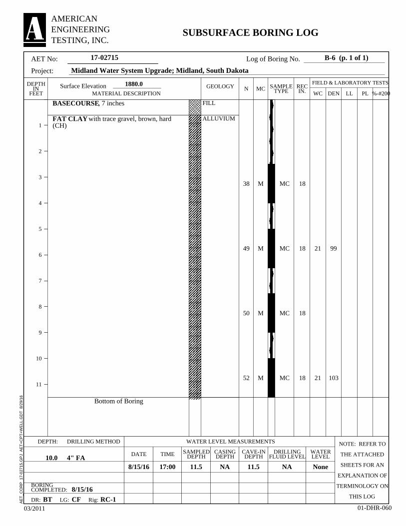
99
103
38
49
50
52
FILL
ALLUVIUM
21
21
M
M
M
M
18
18
18
18
MC
MC
MC
MC
BASECOURSE, 7 inches
FAT CLAY with trace gravel, brown, hard(CH)
Bottom of Boring
11.5
DEPTH: WATER LEVEL MEASUREMENTSDRILLING METHOD NOTE: REFER TO
THE ATTACHED
SHEETS FOR AN
EXPLANATION OF
TERMINOLOGY ON
THIS LOG
CASINGDEPTH
1880.0
8/15/16
CAVE-INDEPTH
Rig:
17:00
Surface Elevation
DR:
11.5
TIME
8/15/16
WATERLEVEL
LG:
BORINGCOMPLETED:
BT
NA
DRILLINGFLUID LEVEL
None
CF
4" FADATE
NA
SAMPLEDDEPTH10.0
RC-1
MC
SUBSURFACE BORING LOG
AET No:
Project:
B-6 (p. 1 of 1)
%-#200LLMATERIAL DESCRIPTIONRECIN.
GEOLOGYDEPTHIN
FEET WCN
03/2011 01-DHR-060
AMERICANENGINEERINGTESTING, INC.
SAMPLETYPE DEN
1
2
3
4
5
6
7
8
9
10
11
FIELD & LABORATORY TESTS
17-02715
Midland Water System Upgrade; Midland, South Dakota
Log of Boring No.
PL
AE
T_C
OR
P
17-0
2715
.GP
J A
ET
+C
PT
+W
ELL
.GD
T
8/29
/16

96
91
34
53
34
33
FILL
ALLUVIUM 23
26
M
M
M
M
18
18
18
18
MC
MC
MC
MC
BASECOURSE, 7 inches
FILL, Fat Clay with trace gravel, brown
FAT CLAY, brown, hard (CH)
Bottom of Boring
11.5
DEPTH: WATER LEVEL MEASUREMENTSDRILLING METHOD NOTE: REFER TO
THE ATTACHED
SHEETS FOR AN
EXPLANATION OF
TERMINOLOGY ON
THIS LOG
CASINGDEPTH
1876.9
8/15/16
CAVE-INDEPTH
Rig:
16:20
Surface Elevation
DR:
11.5
TIME
8/15/16
WATERLEVEL
LG:
BORINGCOMPLETED:
BT
NA
DRILLINGFLUID LEVEL
None
CF
4" FADATE
NA
SAMPLEDDEPTH10.0
RC-1
MC
SUBSURFACE BORING LOG
AET No:
Project:
B-7 (p. 1 of 1)
%-#200LLMATERIAL DESCRIPTIONRECIN.
GEOLOGYDEPTHIN
FEET WCN
03/2011 01-DHR-060
AMERICANENGINEERINGTESTING, INC.
SAMPLETYPE DEN
1
2
3
4
5
6
7
8
9
10
11
FIELD & LABORATORY TESTS
17-02715
Midland Water System Upgrade; Midland, South Dakota
Log of Boring No.
PL
AE
T_C
OR
P
17-0
2715
.GP
J A
ET
+C
PT
+W
ELL
.GD
T
8/29
/16

95
87
40
39
30
33
FILL
ALLUVIUM
26
25
M
M
M
M
18
18
18
18
MC
MC
MC
MC 56
BASECOURSE, 6 inches
FAT CLAY with trace gravel, olive-brown,hard (CH)
Bottom of Boring
20
11.5
DEPTH: WATER LEVEL MEASUREMENTSDRILLING METHOD NOTE: REFER TO
THE ATTACHED
SHEETS FOR AN
EXPLANATION OF
TERMINOLOGY ON
THIS LOG
CASINGDEPTH
1876.2
8/15/16
CAVE-INDEPTH
Rig:
15:35
Surface Elevation
DR:
10.4
TIME
8/15/16
WATERLEVEL
LG:
BORINGCOMPLETED:
BT
NA
DRILLINGFLUID LEVEL
None
CF
4" FADATE
NA
SAMPLEDDEPTH10.0
RC-1
MC
SUBSURFACE BORING LOG
AET No:
Project:
B-8 (p. 1 of 1)
%-#200LLMATERIAL DESCRIPTIONRECIN.
GEOLOGYDEPTHIN
FEET WCN
03/2011 01-DHR-060
AMERICANENGINEERINGTESTING, INC.
SAMPLETYPE DEN
1
2
3
4
5
6
7
8
9
10
11
FIELD & LABORATORY TESTS
17-02715
Midland Water System Upgrade; Midland, South Dakota
Log of Boring No.
PL
AE
T_C
OR
P
17-0
2715
.GP
J A
ET
+C
PT
+W
ELL
.GD
T
8/29
/16

100
97
46
58
40
32
FILL
ALLUVIUM
23
20
M
M
M
M
18
18
18
18
MC
MC
MC
MC
BASECOURSE, 8 inches
FAT CLAY, brown, hard (CH)
Bottom of Boring
11.5
DEPTH: WATER LEVEL MEASUREMENTSDRILLING METHOD NOTE: REFER TO
THE ATTACHED
SHEETS FOR AN
EXPLANATION OF
TERMINOLOGY ON
THIS LOG
CASINGDEPTH
1875.5
8/15/16
CAVE-INDEPTH
Rig:
14:45
Surface Elevation
DR:
11.4
TIME
8/15/16
WATERLEVEL
LG:
BORINGCOMPLETED:
BT
NA
DRILLINGFLUID LEVEL
None
CF
4" FADATE
NA
SAMPLEDDEPTH10.0
RC-1
MC
SUBSURFACE BORING LOG
AET No:
Project:
B-9 (p. 1 of 1)
%-#200LLMATERIAL DESCRIPTIONRECIN.
GEOLOGYDEPTHIN
FEET WCN
03/2011 01-DHR-060
AMERICANENGINEERINGTESTING, INC.
SAMPLETYPE DEN
1
2
3
4
5
6
7
8
9
10
11
FIELD & LABORATORY TESTS
17-02715
Midland Water System Upgrade; Midland, South Dakota
Log of Boring No.
PL
AE
T_C
OR
P
17-0
2715
.GP
J A
ET
+C
PT
+W
ELL
.GD
T
8/29
/16
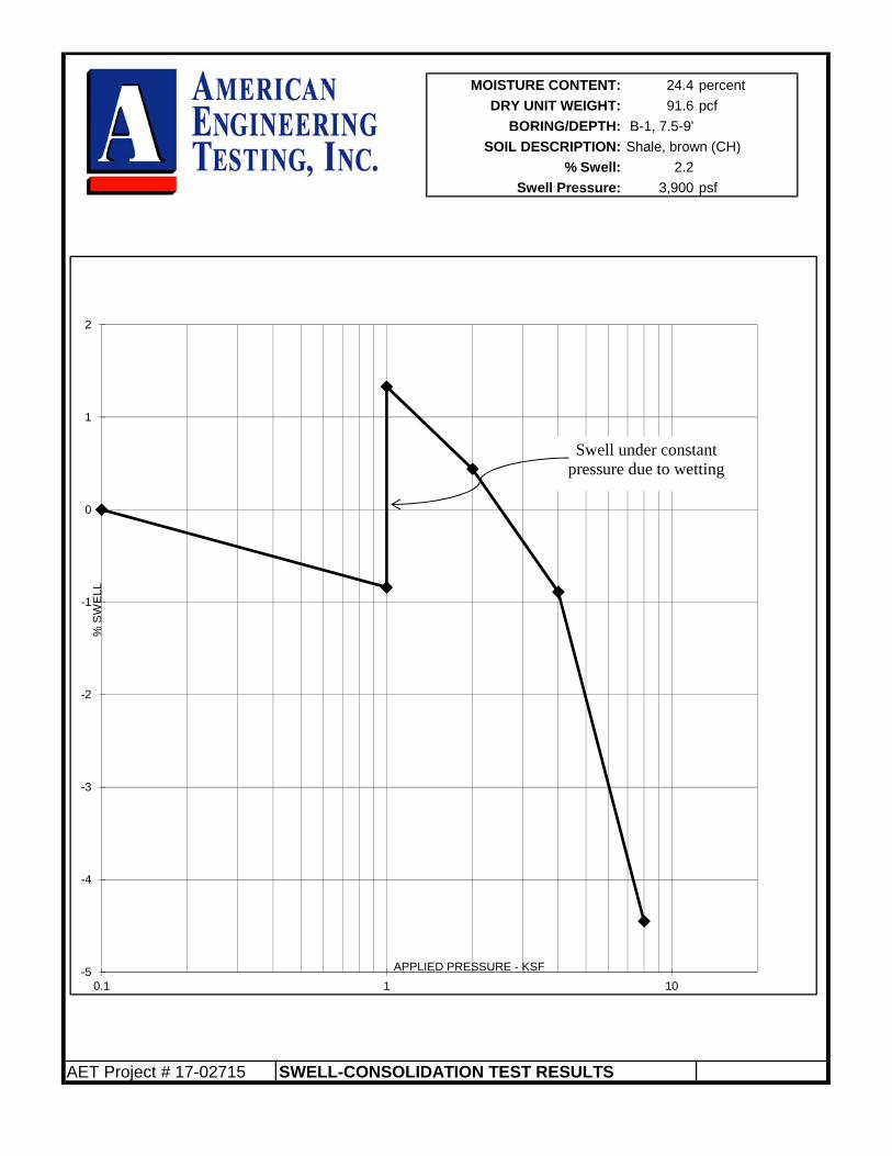
MOISTURE CONTENT: 24.4 percent
DRY UNIT WEIGHT: 91.6 pcf
BORING/DEPTH: B-1, 7.5-9'
SOIL DESCRIPTION: Shale, brown (CH)
% Swell: 2.2
Swell Pressure: 3,900 psf
AET Project # 17-02715 SWELL-CONSOLIDATION TEST RESULTS
-5
-4
-3
-2
-1
0
1
2
0.1 1 10
% S
WE
LL
APPLIED PRESSURE - KSF
Swell under constant pressure due to wetting

75
80
85
90
95
100
105
110
115
120
125
130
135
0 5 10 15 20 25 30 35 40 45
17-02715
PL
MOISTURE-DENSITY RELATIONSHIP
PCF
18.0
DRY
DENSITY
Pounds
Per
Cubic
Foot
109.4
CURVES OF 100% SATURATION
Date
LL
FOR SPECIFIC GRAVITY EQUAL TO:
%
Test Method
(Fill), Fat Clay with sand and a little
gravel, brown (CH)
TEST RESULTS
ATTERBERG LIMITS
2.80
2.60
Job No.
Midland Water System Upgrade
%
Midland, South Dakota
Source of Material
Optimum Water Content
%
Maximum Dry Density
WATER CONTENT (Percent Dry Weight)
Project
Description of Material
ASTM:D698 - Method B
Bulk B-3 0 - 5.0'
PI
2.70
%
AMERICANENGINEERINGTESTING, INC.

Report of Geotechnical Exploration and Review Proposed Midland Water System AMERICAN August 30, 2016 ENGINEERING Report No. 17-02715 TESTING, INC.
Appendix B
Geotechnical Report Limitations and Guidelines for Use

Geotechnical Report Limitations and Guidelines for Use AET Project No. 17-02715
Appendix - Page 1 of 2 AMERICAN ENGINEERING TESTING, INC.
REFERENCE This appendix provides information to help you manage your risks relating to subsurface problems which are caused by construction delays, cost overruns, claims, and disputes. This information was developed and provided by ASFE1, of which, we are a member firm. RISK MANAGEMENT INFORMATION Geotechnical Services are Performed for Specific Purposes, Persons, and Projects Geotechnical engineers structure their services to meet the specific needs of their clients. A geotechnical engineering study conducted for a civil engineer may not fulfill the needs of a construction contractor or even another civil engineer. Because each geotechnical engineering study is unique, each geotechnical engineering report is unique, prepared solely for the client. No one except you should rely on your geotechnical engineering report without first conferring with the geotechnical engineer who prepared it. No one, not even you, should apply the report for any purpose or project except the one originally contemplated. Read the Full Report Serious problems have occurred because those relying on a geotechnical engineering report did not read it all. Do not rely on an executive summary. Do not read selected elements only. A Geotechnical Engineering Report is Based on A Unique Set of Project-Specific Factors Geotechnical engineers consider a number of unique, project-specific factors when establishing the scope of a study. Typically factors include: the client’s goals, objectives, and risk management preferences; the general nature of the structure involved, its size, and configuration; the location of the structure on the site; and other planned or existing site improvements, such as access roads, parking lots, and underground utilities. Unless the geotechnical engineer who conducted the study specifically indicates otherwise, do not rely on a geotechnical engineering report that was:
not prepared for you, not prepared for your project, not prepared for the specific site explored, or completed before important project changes were made.
Typical changes that can erode the reliability of an existing geotechnical engineering report include those that affect:
the function of the proposed structure, as when it’s changed from a parking garage to an office building, or from a light industrial plant to a refrigerated warehouse,
elevation, configuration, location, orientation, or weight of the proposed structure, composition of the design team, or project ownership.
As a general rule, always inform your geotechnical engineer of project changes, even minor ones, and request an assessment of their impact. Geotechnical engineers cannot accept responsibility or liability for problems that occur because their reports do not consider developments of which they were not informed. Subsurface Conditions Can Change A geotechnical engineering report is based on conditions that existed at the time the study was performed. Do not rely on a geotechnical engineering report whose adequacy may have been affected by: the passage of time; by man-made events, such as construction on or adjacent to the site; or by natural events, such as floods, earthquakes, or groundwater fluctuations. Always contact the geotechnical engineer before applying the report to determine if it is still reliable. A minor amount of additional testing or analysis could prevent major problems. 1 ASFE, 8811 Colesville Road/Suite G106, Silver Spring, MD 20910 Telephone: 301/565-2733 : www.asfe.org

Geotechnical Report Limitations and Guidelines for Use AET Project No. 17-02715
Appendix - Page 2 of 2 AMERICAN ENGINEERING TESTING, INC.
Most Geotechnical Findings Are Professional Opinions Site exploration identified subsurface conditions only at those points where subsurface tests are conducted or samples are taken. Geotechnical engineers review field and laboratory data and then apply their professional judgment to render an opinion about subsurface conditions throughout the site. Actual subsurface conditions may differ, sometimes significantly, from those indicated in your report. Retaining the geotechnical engineer who developed your report to provide construction observation is the most effective method of managing the risks associated with unanticipated conditions. A Report’s Recommendations Are Not Final Do not over rely on the construction recommendations included in your report. Those recommendations are not final, because geotechnical engineers develop them principally from judgment and opinion. Geotechnical engineers can finalize their recommendations only by observing actual subsurface conditions revealed during construction. The geotechnical engineer who developed your report cannot assume responsibility or liability for the report’s recommendations if that engineer does not perform construction observation. A Geotechnical Engineering Report Is Subject to Misinterpretation Other design team members’ misinterpretation of geotechnical engineering reports has resulted in costly problems. Lower that risk by having your geotechnical engineer confer with appropriate members of the design team after submitting the report. Also retain your geotechnical engineer to review pertinent elements of the design team’s plans and specifications. Contractors can also misinterpret a geotechnical engineering report. Reduce that risk by having your geotechnical engineer participate in prebid and preconstruction conferences, and by providing construction observation. Do Not Redraw the Engineer’s Logs Geotechnical engineers prepare final boring and testing logs based upon their interpretation of field logs and laboratory data. To prevent errors or omissions, the logs included in a geotechnical engineering report should never be redrawn for inclusion in architectural or other design drawings. Only photographic or electronic reproduction is acceptable, but recognize that separating logs from the report can elevate risk. Give Contractors a Complete Report and Guidance Some owners and design professionals mistakenly believe they can make contractors liable for unanticipated subsurface conditions by limiting what they provide for bid preparation. To help prevent costly problems, give contractors the complete geotechnical engineering report, but preface it with a clearly written letter of transmittal. In the letter, advise contractors that the report was not prepared for purposes of bid development and that the report’s accuracy is limited; encourage them to confer with the geotechnical engineer who prepared the report (a modest fee may be required) and/or to conduct additional study to obtain the specific types of information they need to prefer. A prebid conference can also be valuable. Be sure contractors have sufficient time to perform additional study. Only then might you be in a position to give contractors the best information available to you, while requiring them to at least share some of the financial responsibilities stemming from unanticipated conditions. Read Responsibility Provisions Closely Some clients, design professionals, and contractors do not recognize that geotechnical engineering is far less exact than other engineering disciplines. This lack of understanding has created unrealistic expectations that have led to disappointments, claims, and disputes. To help reduce the risk of such outcomes, geotechnical engineers commonly include a variety of explanatory provisions in their report. Sometimes labeled “limitations” many of these provisions indicate where geotechnical engineers’ responsibilities begin and end, to help others recognize their own responsibilities and risks. Read these provisions closely. Ask questions. Your geotechnical engineer should respond fully and frankly. Geoenvironmental Concerns Are Not Covered The equipment, techniques, and personnel used to perform a geoenvironmental study differ significantly from those used to perform a geotechnical study. For that reason, a geotechnical engineering report does not usually relate any geoenvironmental findings, conclusions, or recommendations; e.g., about the likelihood of encountering underground storage tanks or regulated contaminants. Unanticipated environmental problems have led to numerous project failures. If you have not yet obtained your own geoenvironmental information, ask your geotechnical consultant for risk management guidance. Do not rely on an environmental report prepared for someone else.