report on hand movement controlled
DESCRIPTION
Report On Hand Movement Controlled Wireless Bot Using MicrocontrollerTRANSCRIPT
Dissertation Report OnHAND MOVEMENT CONTROLLED WIRELESS BOT USING
MICROCONTROLLER
Submitted to Amity University Uttar Pradesh
In partial fulfillment of the requirements for the award of the degree of Master of Technology
In
Electronics & Communication Engineering
By
SHANTANU
(A2315312043)
under the guidance of
Mr. Manish Sharma Mr. Gagan MinochaAssistant Professor Assistant ProfessorASET, Noida ASET, Noida Faculty Guide Faculty Guide
DEPARTMENT OF ELECTRONICS & COMMUNICATION ENGINEERINGAMITY SCHOOL OF ENGINEERING AND TECHNOLOGY
AMITY UNIVERSITY UTTAR PRADESHNOIDA (U.P.)

CERTIFICATE
On the basis of declaration submitted by SHANTANU student of M.Tech (ECE) I hereby certify that the project titled “HAND MOVEMENT CONTROLLED WIRELESS BOT USING MICROCONTROLLER” which is submitted to Department of ASET(Amity School of Engineering and Technology), Amity University (Uttar Pradesh), Noida. In the fulfillment of the requirement for the award of the degree of Master of Technology in ECE, is an original contribution with existing knowledge and faithful record of work carried out by him under my guidance and supervision.
By the best of my knowledge this work has not been submitted partially or fully for any Degree or Diploma to this University or elsewhere.
Mr. Manish Sharma
(Assistant Professor)
Department of ECE
ASET, Noida
Mr. Gagan Minocha
(Assistant Professor)
Department of ECE
ASET, Noida
ii
ACKNOWLEDGEMEMT
I would like to express my special thanks of gratitude to my faculty Guide Mr. MANISH SHARMA and Mr. GAGAN MINOCHAwho gave me the golden opportunity to do this highly intellectual and technical project report on the topic “HAND MOVEMENT CONTROLLED WIRELESS BOT USING MICROCONTROLLER” which also helped me in doing a lot of research and I came to know about so many things.
I am really thankful to them.
Secondly I would like to thank my parents and friends who helped me a lot in finishing
this project within given time limit.
This project had given me a scope to widen my area of expertise on the topic, for which I
thank everyone who have helped me to complete it successfully.
Shantanu
(M.Tech- ECE)
A2315312043
Amity University Noida
iii

ABSTRACT
This thesis is all about wireless communication between two wireless modules, a bot and
a hand movement controlled device having accelerometer on it. It has been seen that
controlling a remote device is quiet a difficult task but in order to make it easy there is a
technology which uses a free radio frequency of 2.4 GHz with 16 channels called as
Zigbee[7] , keeping all wireless IEEE 802.15.4 global open standard true.
According to this technology, one is able to control a remote device easily from a far
distance site and can make (order) any kind of movement to its remote device. And by
doing so the difficult task of controlling a device from a distant point would have become
a cup of tea for its master and also a low cost effort for a better result.
In this a transmitting section which is having accelerometer [2] (MEMS technology) tilt
sensor in order to measure the tilt and transmit it wirelessly with the help of Zigbee
along with the use of microcontroller AVR ATmega8[1][7]. This project also requires a
pre-requisite knowledge of microcontroller programming to develop logics to operate the
device. The receiving section mounted on robot and it receives control signals from
transmitting section according to the tilt of the platform in order to control direction of
robot and we can also use the concept of PWM to control the speed of chair with
respect to tilt value.
iv
TABLE OF CONTENT
SNo. CONTENTS Page No.
1. ABSTRACT iv2. CHAPTER 1. INTRODUCTION 13. 1.1 REVIEW OF LITERATURE 14. 1.2 OBJECTIVE 25. CHAPTER 2. BLOCK DIAGRAM 36. 2.1 TRANSMITTER BLOCK DIAGRAM 37. 2.2 RECEIVER BLOCK DIAGRAM 38. 2.3 DATA FLOW DIAGRAM 49. 2.3.1 TRANSMITTER SIDE 410. 2.3.2 RECEIVER SIDE 511. CHAPTER 3. CIRCUIT DIAGRAM 612. 3.1 TRANSMITTER CIRCUIT DIAGRAM 613. 3.2 RECEIVER CIRCUIT DIAGRAM 914. 3.3 ZIGBEE MODEM TECHNOLOGY (CC2500) 1015. 3.3.1 FEATURES 1016. 3.3.2 SPECIFICATIONS 1117. CHAPTER 4. LIST OF COMPONENTS 1318. 4.1 SUPPLY SECTION BOARD 1319. 4.2 CONTROLLER SECTION BOARD 1420. CHAPTER 5. DETAILS OF COMPONENTS 1421. 5.1 MICROCONTOLLER(AVR ATmega8) 1522. 5.1.1 FEATURES 1523. 5.1.2 PIN DIAGRAM(ATmega8) 1624. 5.1.3 PIN DESCRIPTION 1625. 5.1.4 IN SYSTEM REPROGRAMMABLE FLASH PROGRAM
MEMORY18
26. 5.2 LED(LIGHT EMITTING DIODE) 2027. 5.3 DIODES 2028. 5.4 CAPACITORS 2129. 5.5 RESISTORS 2330. 5.6 REGULATORS 2431. 5.7BREAKAWAY CONNECTORS 2532. 5.8 DPDT SWITCH 2533. 5.9 LCD(LIQUID CRYSTAL DISPLAY-16x2) 2634. 5.10 ACCELEROMETER 2635. 5.11 L293D 2836. 5.11.1 PIN DESCRIPTION 2937. 5.12 CRYSTAL 3038. 5.13 DC MOTORS 3039. 5.14 ROBOT BODY 3140. 5.15 SUPPLY BOARD 3341. CHAPTER 6. DETAILS OF COMPONENT 34
v

42. 6.1 SOFTWARE DEVELOPMENT 3443. 6.2 CODING/DEBUGGING 3444. 6.3 STEP BY STEP CODING OF WMSM PROGRAM 3545. CHAPTER 7. PROGRAMMING 3946. 7.1 TRANSMITTER PROGRAMMING 3947. 7.2 MOTORS WORKING WITH LCD 3948. 7.3 LCD PROGRAMMING 4049. 7.4 MOTOR BITWISE OPERATION 4350. 7.5 PROGRAMMING OF TRANSMITTER MODULE 4551. 7.6 PROGRAMMING OF RECEIVER MODULE 4852. CHAPTER 8. PROJECT DESCRIPTION 5153. 8.1 DESCRIPTION 5154. CHAPTER 9. RESULTS 5255. 9.1TRANSMITTER SECTION 5256. 9.2 RECEIVER SECTION 5757. 9.3 ADVANTAGES 6058. 9.4 LIMITATIONS 6059. 9.5 CONCLUSION 6060. 9.6 FUTURE PROSPECT 6061. 9.7 REFERENCES 61
vi
LIST OF FIGURES AND TABLES
SNo FIGURESPage No.
1. Figure.1 Transmitter module Block diagram 32. Figure.2 Receiver module Block diagram 33. Figure.3 Data Flow Diagram (Transmitter) 44. Figure.4 Data Flow Diagram (Receiver) 55. Figure.5 Circuit diagram of Transmitter 86. Figure.6 Circuit diagram of Receiver 107. Figure.7 A Zigbee Modem (CC2500) 118. Figure.8 Zigbee Networks(three types) 129. Figure.9 Atmega8 microcontroller 1610. Figure.10 AVR ATmega8 Flash memory 1911. Figure.11 LED (Light Emitting Diode) 2012. Figure.12(a),(b) PN junction diode (1N4007) 2113. Figure.13 Capacitor (1000µF, 35 Volts) 2214. Figure.14(a),(b) Resistors 2315. Figure.15(a),(b) Regulators 2416. Figure.16 Male connector 2517. Figure.17 Female connector 2518. Figure.18(a),(b) DPDT switch 2519. Figure.19(a),(b) LCD (Liquid Crystal Display) 2620. Figure.20 Accelerometer 2721. Figure.21 L293D 2822. Figure.22 Pin diagram(L293D) 2823. Figure.23 Crystal 3024. Figure.24 DC motors 3025. Figure.25 Robot transmitter diagram 3126. Figure.26 Robot Body 3227. Figure.27 Power supply 3328. Figure.28 Software Development 3429. Figure.29 Step1 coding/ debugging 3530. Figure.30 Step2 coding/ debugging 3631. Figure.31 Step3 coding/ debugging 3632. Figure.32 Step4 coding/ debugging 3733. Figure.33 Step5 coding/ debugging 3734. Figure.34 Step6 coding/ debugging 3835. Figure.35 Power supply(side view) 5236. Figure.36 Power supply (top view) 5337. Figure.37 Zigbee module 53
vii

38. Figure.38 Transmitter module 5439. Figure.39 LCD display (Stable direction) 5440. Figure.40 LCD display (Left direction) 5541. Figure.41 LCD display (Forward direction) 5542. Figure.42 LCD display (Reverse direction) 5643. Figure.43 LCD display (Right direction) 5644. Figure.44 Receiver module 5745. Figure.45 LCD display (Stable direction) 5746. Figure.46 LCD display (Left direction) 5847. Figure.47 LCD display (Forward direction) 5848. Figure.48 LCD display (Reverse direction) 5949. Figure.49 LCD display (Right direction) 59
List of tables
SNo Table Page No.
1. Table 1 : Pin description(L293D) 29
viii
LIST OF ABBREVATIONS
S.No ACRONYMS USED1. µF: microfarad2. pF: pocofarad3. LED: Light Emitting Diode4. IEEE: Institute of Electrical and Electronics Engineers5. MEMS: Microelectromechanical systems6. PWM: Pulse width modulation7. LCD: Liquid Crystal Display8. MODEM: Modulator- Demodulator9. CRC: Cyclic redundancy check10. TTL: Transistor-Transistor logic11. UART: Universal asynchronous receiver/transmitter12. dbm: Decibel-milliwatts13. GHz: Giga hertz14. MHz: Mega hertz15. DPDT: Dual pole, dual throw16. EEPROM: Electrically Erasable Programmable Rom17. SRAM: Static Random Access Memory18. ADC: Analog to Digital Converter19. PDIP: Dual-Inline package20. GND: Ground21. SPI: Serial Peripheral Interface22. DC: Direct Current23. AC: Alternating Current24. IC: Integrated Circuit25. ppm: part per million26. pcb: printed circuit board
ix

CHAPTER 1: INTRODUCTION
This project is consist of a bot (robot)[4][5] , which is called as a mechanical device,
artificial agent or a model and also having a programmable device which control its
movements. So it is usually that system, which by its appearance and by its movements
conveys a sense which has a tendency to work on its own. A typical robot will have
several properties as follows:
It is artificially created can sense its environment, and manipulate or interact with things around it has a degree of intelligence and ability to make choices based on its environment
by using different kinds of sensor it possess automatic control or a preprogrammed sequence and programmable
moves with one or more axes of rotation or translation makes dexterous coordinated movements appears to have intent or agency.
1.1 REVIEW OF LITERATURE
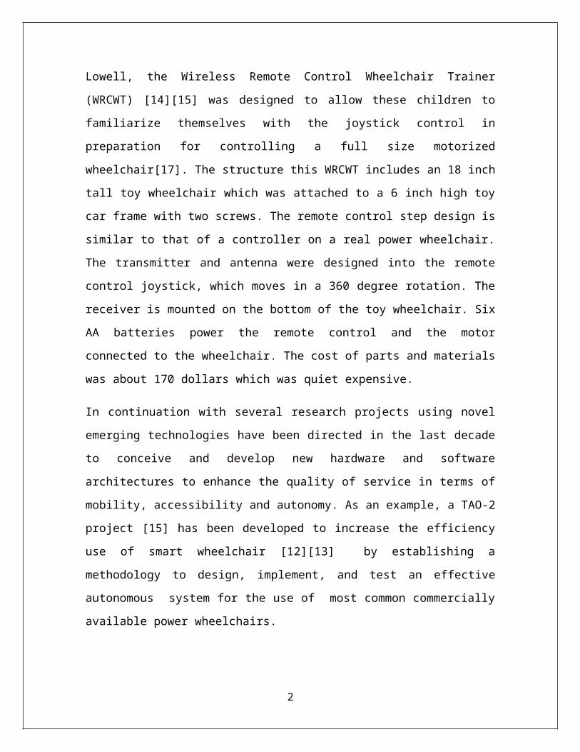
A wireless [8] remote control wheelchair created for children with mobility disabilities
at a hospital, by an engineering student at the University of Massachusetts at Lowell, the
Wireless Remote Control Wheelchair Trainer (WRCWT) [14][15] was designed to allow
these children to familiarize themselves with the joystick control in preparation for
controlling a full size motorized wheelchair[17]. The structure this WRCWT includes an
18 inch tall toy wheelchair which was attached to a 6 inch high toy car frame with two
screws. The remote control step design is similar to that of a controller on a real power
wheelchair. The transmitter and antenna were designed into the remote control joystick,
which moves in a 360 degree rotation. The receiver is mounted on the bottom of the toy
wheelchair. Six AA batteries power the remote control and the motor connected to the
wheelchair. The cost of parts and materials was about 170 dollars which was quiet
expensive.
1

In continuation with several research projects using novel emerging technologies have
been directed in the last decade to conceive and develop new hardware and software
architectures to enhance the quality of service in terms of mobility, accessibility and
autonomy. As an example, a TAO-2 project [15] has been developed to increase the
efficiency use of smart wheelchair [12][13] by establishing a methodology to design,
implement, and test an effective autonomous system for the use of most common
commercially available power wheelchairs.
So the idea is to make use of and overcoming the drawback of a previously designed
existing model in order to reduce the amount of effort and user commands to enhance the
dependability of the wireless controlled device.
1.2OBJECTIVE
The main aim of this project is to develop a user friendly wireless radio frequency Bot.
We are building a device which would help us to deal with areas where surrounding is
not favorable for human beings. In this project we are using the Zigbee Technology [7]
(IEEE 802.15.4).
We are trying to demonstrate its way of functionality and various aspects like kinds,
advantages by using a small application of controlling an electronic device through a
remote.
2

REGULATED POWER SUPPLY (+ 5 Volts)
ACCELEROMETERZIGBEE TRANSMITTER
MICROCONTROLLER DISPLAY(LCD 1)
SWITCHES
ZIGBEE RECEIVER
REGULATED POWER SUPPLY(+5 Volts)
MICROCONTROLLER
LCD 2
L293D
M1
M2
CHAPTER 2. BLOCK DIAGRAM
In this section the flow chart of the working of project is described.
2.1 TRANSMITTER BLOCK DIAGRAM
Figure.1: Transmitter Module Block Diagram
2.2 RECEIVER BLOCK DIAGRAM
Figure.2: Receiver Module Block Diagram
3
LCD displays With Left, Right, Forward, Reverse&
Stable
Transmit coordinates using Zigbee cc2500 module
Start(Initialize the System)
Read the Accelerometer (ADC Pin)
Match the coordinate of X & Y axis Y axisX axis
2.3 DATA FLOW DIAGRAM
In this section the whole date flow of the project system is explained by the data flow diagram.
2.3.1 Transmitter Side
Figure.3: Data Flow Diagram (Transmitter)
4

Bot is moving accordingly instruction
Right WheelLeft wheel
Initialize the System
Wirelessly receive the data using Zigbee cc2500
Match the data with database
2.3.2 Receiver side
Figure.4: Data Flow Diagram (Transmitter)
5

CHAPTER 3. CIRCUIT DIAGRAM
In this section the circuit buildup of project having transmitter and receiver module is described.
3.1 TRANSMITTER CIRCUIT DIAGRAM
The transmitter module contains a LCD display, ATmega8 microcontroller [2][3],
L293D, two motors and a MODEM module. These all are connected together and
working as a transmitter for the project model.
As the microcontroller used is ATmega8 having 28 pins [7] port pins, having four ports
as A,B, C,D.
These ports are utilized by the LCD, Motors and L293D. Pin 9 is kept free , it is the reset
pin.
So the connections are made in this manner :-
Pin 1(Port B0) of ATmega8 microcontroller is connected to Pin 2 (input 1) of
L293D.
Pin 2(Port B1) of ATmega8 microcontroller is connected to Pin 7 (input 2) of
L293D.
Pin 3(Port B2) of ATmega8 microcontroller is connected to Pin 10 (input 3) of
L293D.
Pin 4(Port B3) of ATmega8 microcontroller is connected to Pin 15 (input 4) of
L293D.
Pin 22(Port C0) of ATmega8 microcontroller is connected to Pin 11 (Port D4) of
LCD.
Pin 23(Port C1) of ATmega8 microcontroller is connected to Pin 12 (Port D5) of
LCD.
Pin 24(Port C2) of ATmega8 microcontroller is connected to Pin 13 (Port D6) of
LCD.
6

Pin 25(Port C3) of ATmega8 microcontroller is connected to Pin 14 (Port D7) of
LCD.
Pin 9(ENABLE 2) of L293D is connected to Pin 1 (ENABLE 1), Pin16(+ 12 V
supply) and Pin 8 (Vs) of L293D.
Motors output are connected to Pin 3 (OUTPUT)1 , Pin 6(OUTPUT 2),Pin 11
(OUTPUT 3) and Pin 14 (OUTPUT 4) of L293D.
Pin 16 (Port D2) is connected to RF Modem’s Vcc.
Ground (Gnd) of modem is connected to Pin 15 (Port D1).
7

Figure.5: Circuit Diagram of Transmitter
8

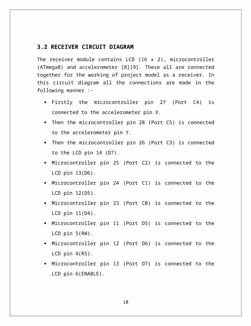
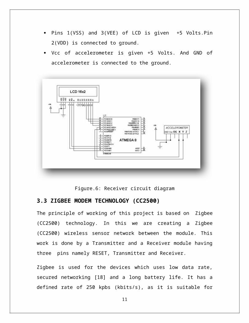
3.2 RECEIVER CIRCUIT DIAGRAM
The receiver module contains LCD (16 x 2), microcontroller (ATmega8) and accelerometer [8][9]. These all are connected together for the working of project model as a receiver. In this circuit diagram all the connections are made in the following manner :-
Firstly the microcontroller pin 27 (Port C4) is connected to the accelerometer pin
X.
Then the microcontroller pin 28 (Port C5) is connected to the accelerometer pin
Y.
Then the microcontroller pin 26 (Port C3) is connected to the LCD pin 14 (D7).
Microcontroller pin 25 (Port C2) is connected to the LCD pin 13(D6).
Microcontroller pin 24 (Port C1) is connected to the LCD pin 12(D5).
Microcontroller pin 23 (Port C0) is connected to the LCD pin 11(D4).
Microcontroller pin 11 (Port D5) is connected to the LCD pin 5(RW).
Microcontroller pin 12 (Port D6) is connected to the LCD pin 4(RS).
Microcontroller pin 13 (Port D7) is connected to the LCD pin 6(ENABLE).
Pins 1(VSS) and 3(VEE) of LCD is given +5 Volts.Pin 2(VDD) is connected to
ground.
Vcc of accelerometer is given +5 Volts. And GND of accelerometer is connected
to the ground.
9

Figure.6: Receiver circuit diagram
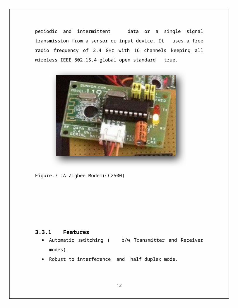
3.3 ZIGBEE MODEM TECHNOLOGY (CC2500)
The principle of working of this project is based on Zigbee (CC2500) technology. In this
we are creating a Zigbee (CC2500) wireless sensor network between the module. This
work is done by a Transmitter and a Receiver module having three pins namely RESET,
Transmitter and Receiver.
Zigbee is used for the devices which uses low data rate, secured networking [18] and a
long battery life. It has a defined rate of 250 kpbs (kbits/s), as it is suitable for periodic
and intermittent data or a single signal transmission from a sensor or input device. It
uses a free radio frequency of 2.4 GHz with 16 channels keeping all wireless IEEE
802.15.4 global open standard true.
10
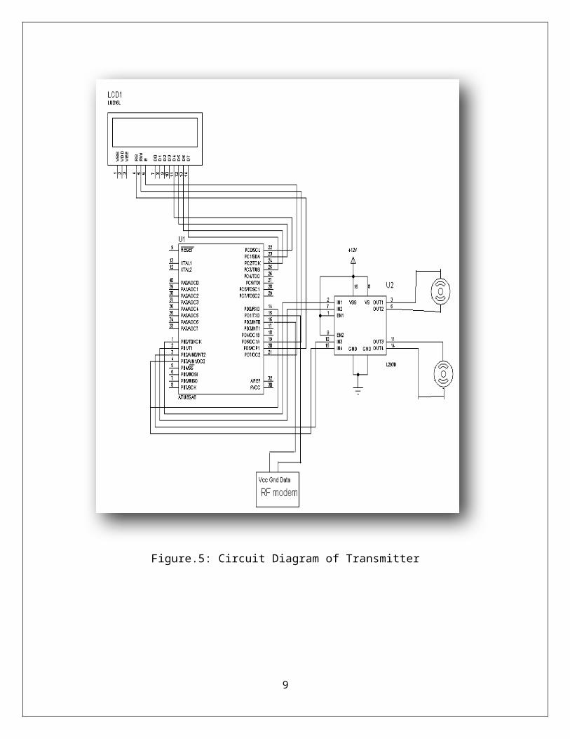
Figure.7 :A Zigbee Modem(CC2500)
3.3.1 Features Automatic switching ( b/w Transmitter and Receiver modes).
Robust to interference and half duplex mode.
2.4 GHz band (no need for applying the frequency usage license).
Self-controlled protocol translation and easy to use.
Highly sensitive and reliable for transmission range.
Standard UART interface and TTL ( + 3V to +5V) logic level.
Small in size, stable and easy to mount.
In built error checking (CRC) of data.
11
3.3.2 Specifications Working voltage-Min- 4.5 Volts , Max- 9 Volts
Frequency of Operation- 2.4 GHz
Output RF Power- 1 dbm
Typical Operation Range- 30 meters
UART baud rate (8 bit data, no parity, 1 stop bit)- 9600/4800/38400/19200 bps.
ZigBee network uses three types of devices:
ZigBee Coordinator
Zigbee Router
ZigBee End Device
Figure.8: Zigbee Networks(three types)
12
CHAPTER 4. LIST OF COMPONENTS
In this section the list of components, both supply section and controller section used
in the project is described.
4.1 SUPPLY SECTION BOARD
Diode (1N4007).
Capacitor (1000µf/35 Volts).
DPDT Switch.
Regulator 7805.
Resistors (330 ohms).
LED ( +3.5 Volts)
Programmer connector
4.2 CONTROLLER SECTION BOARD
Diode (1N4007).
Capacitor (1000µf/35 Volts)
Microcontroller ATmega8 (8Kb flash memory )
Breakaway connector.
LCD(16x2 )
L293D
Motors
13
CHAPTER 5. DETAILS OF COMPONENT (Hardware)
In this section the all the details regarding project hardware is described .
5.1 MICROCONTROLLER ( AVR ATmega8 )
The ATmega8 is a low-power 8-bit CMOS microcontroller based on the AVR RISC
(Reduced instruction cycle) architecture with 8K bytes in-system programmable flash
memory.
It is having the property of deploying powerful instructions in a single clock cycle, the
microcontroller achieves throughputs upto 1 MIPS per MHz and allows the system
designer to optimize the power consumption and processing speed.
5.1.1 Features AVR 8-bit Microcontroller (High-performance and Low-power).
Advanced RISC Architecture
i. Powerful 130 instructions(single clock cycle execution).
ii. 32 x 8 general purpose working registers.
iii. Full static operation.
iv. Up to 16 MIPS throughput at 16 MHz.
v. 2- cycle multiplier(on chip).
High non-volatile memory segments
i. In system self -programmable Flash memory(8K bytes).
ii. EEPROM(512 Bytes).
iii. Internal SRAM(1K Bytes).
iv. Retention of data- 20 years at 85 °C /100 years at 25 °C.
Peripheral Features
i. Two 8-bit Timers/Counters.
ii. One 16-bit Timer/Counter.
iii. Three PWM channels.
iv. 8-channel ADC in TQFP and QFN/MLF package.
14

Eight channels 10-bit accuracy
i. Six channels ADC in PDIP package.
Six channel 10-bit accuracy
i. Two- wire serial Interface (byte oriented).
ii. Programmable serial USART.
iii. Master/ Slave SPI serial interface.
iv. On chip analog comparator.
I/O and packages
i. Programmable I/O lines (23).
ii. Lead PDIP(28), 32- lead TQFP and 32-pad QFN/MLF.
Operating Voltages
i. 2.7 Volts- 5.5 Volts (ATmega8L).
ii. 4.5 Volts- 5.5 Volts (ATmega8).
Speed
i. 0- 8 MHz (ATmega8L).
ii. 0-16 MHz (ATmega8).
Power Consumption ( 4MHz, 3V, 25 °C)
i. Active- 3.6 mA.
ii. Idle mode- 1.0 mA.
iii. Power down mode- 0.5 µA.
15

5.1.2 PIN DIAGRAM(ATmega8 microcontroller)
Figure.9: ATmega8 microcontroller
5.1.3 PIN DESCRIPTION
VCC - Digital supply voltage.
GND - Ground.
Port B (PB7- PB0)
Port B is an 8-bit bi-directional I/O (input/output) port with internal pull-up
resistors.
16

PB6 can be used as an input for the inverting Oscillator amplifier and an input
to the internal clock operating circuit.
PB7 will be used as output (from inverting Oscillator amplifier).
PB7 (pin 10) and PB6 (pin 9) are used as input for the Asynchronous
Timer/Counter2.
Port C (PC5- PC0)
Port C is an 7-bit bi-directional I/O(input/output) port with internal pull-up
resistors (selected for each bit).
PC6 (RESET)-pin 1, is used as an I/O (input/output) pin because of the electrical
characteristics of PC6 differ from those of the other pins of Port C.
PC6 is used as a reset input when the RSTDISBL Fuse is un-programmed.
Port D (PD7- PD0)
Port D is an 8-bit bi-directional I/O (input/output) port with internal pull-up
resistors (selected for each bit).
Pin 2 (PD0) works for configuring the receiver and pin 3(PD1) works for the
configuring the transmitter.
AVCC AVCC is the supply voltage pin for Port C (3-0) and ADC (7-6).
It should be externally connected to VCC, even if the ADC is not usable.
Port C5 a nd Port C4 uses digital supply voltage(VCC).
AREF
It the analog reference pin for the A/D Converter.
17

ADC7-ADC6 (TQFP and QFN/MLF Package Only)
In the TQFP and QFN/MLF package, ADC7- ADC6 serves as analog inputs to
the Analog/Digital converter.
AVR ATmega8 Memories
This section describes the different memories in the ATmega8.
It has two main memory spaces as Data memory and Program Memory space.
ATmega8 also has an EEPROM Memory for data storage.
All the above three memory spaces are linear and regular.
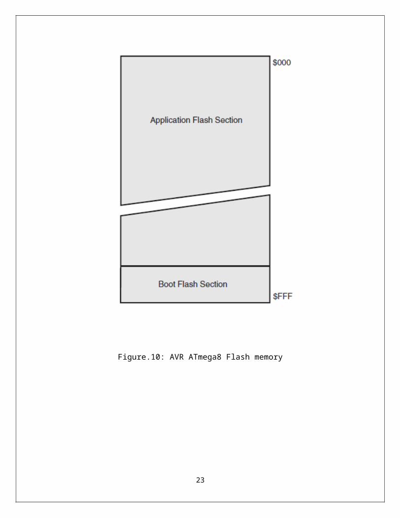
5.1.4 In-System Reprogrammable Flash Program Memory
ATmega8 has on-chip In-System Reprogrammable Flash memory (8K bytes) for
the program storage. This is available in 16 or 32-bits.
For the software security purpose, the Flash Program memory space is divided
into two sections as Boot Program section and Application Program section.
The Flash memory has a capacity of at least 10,000 (approx.) write and erase
cycles.
ATmega8 Program Counter (PC) is 12 bits wide, thus addresses the 4K program
memory locations in SPI (Parallel Programming mode) .
18

Figure.10: AVR ATmega8 Flash memory
19

5.2 LIGHT EMITTING DIODE(LED)
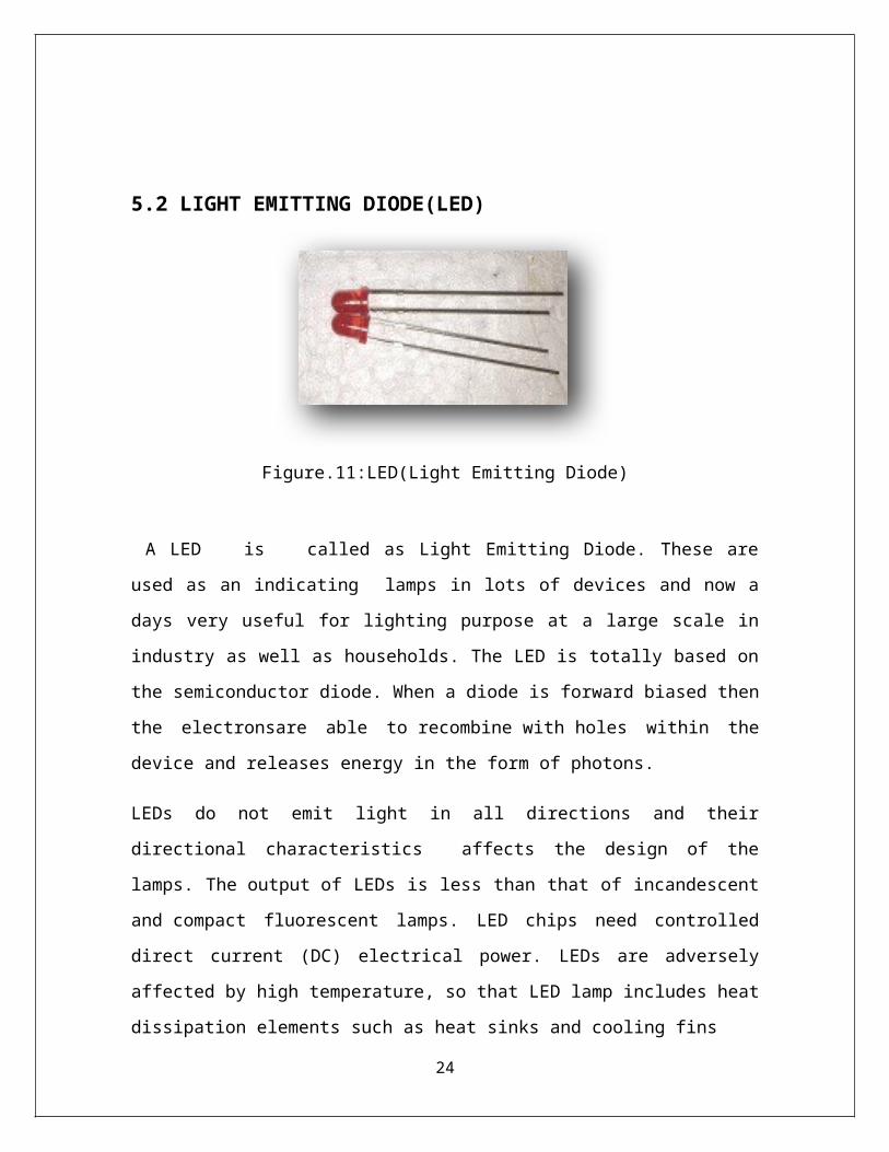
Figure.11:LED(Light Emitting Diode)
A LED is called as Light Emitting Diode. These are used as an indicating lamps in
lots of devices and now a days very useful for lighting purpose at a large scale in industry
as well as households. The LED is totally based on the semiconductor diode. When a
diode is forward biased then the electronsare able to recombine with holes within the
device and releases energy in the form of photons.
LEDs do not emit light in all directions and their directional characteristics affects the
design of the lamps. The output of LEDs is less than that of incandescent and compact
fluorescent lamps. LED chips need controlled direct current (DC) electrical power. LEDs
are adversely affected by high temperature, so that LED lamp includes heat
dissipation elements such as heat sinks and cooling fins
5.3 DIODES
A diode [19][20] is a simplest form of semiconductor device that is it has two terminals
between which electrical current conducts in only one direction. Thus it is a
semiconductor material which conducts electricity with varying ability. So the
conduction or the flow or current in one direction is called as diode’s forward direction
and blocking current in opposite direction is called as reverse direction.
20
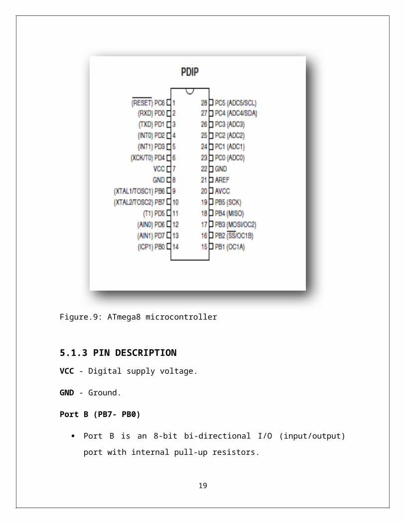
Figure.(a) Figure.(b)
Figure.12 (a),(b): PN junction Diode (1N4007)
This unidirectional behavior of the diode is called rectification and it is used to convert AC ( alternating current ) to DC (direct current ) and extracts modulation from the radio signals in radio receivers. Due to their complex non-linear electrical characteristics, which can be changed by varying the construction of their P-N junction. Diodes are used to regulate voltage ( usually Zener diodes) electronically tuned radios and TV receivers (Varactor diodes), generate radio frequency oscillations (tunnel diodes), and produce light (light emitting diode).
5.4 CAPACITORS
A capacitor is passive, two terminal device used to store energy electrostatically in
an electric field. It contains nearly two electrical conductors (plates) which are separated
by a dielectric which acts as an insulator. When a potential difference (voltage) occurs
across the conductors then an electric field will be generated in the dielectric. This field
stores energy and produces a mechanical force between the conductors. The effect is
more when there is a separation between the large areas of conductors , hence a
capacitor conductors are also called plates.
21

Figure.13: Capacitor (1000 microfarad, 35Volts)
According to the characteristics of an ideal capacitor, is having a single constant value that is also called as capacitance ( farads).
The capacitors are used in electronic circuits in order to block the flow of direct current, allowing the alternating current to pass and to smoothen the output of power supplies etc. They are used in resonant circuits in radio frequency equipment to select particular frequencies from a signal with many frequencies.
The standard unit of capacitance is the farad, abbreviated. This is a large unit and more
common units are
microfarad, abbreviated µF (1 µF =10-6F) .
picofarad, abbreviated pF (1 pF = 10-12 F).
The large capacitors are used in the power supplies of electronic equipment, which
includes computers and their peripherals.
22

5.5 RESISTORS
A resistor is a two-terminal electronic component that produces a voltage across its
terminals.
The voltage (potential difference) is proportional to the electric current passing through
and called Ohm's law:
V = IR ………………………………… (1)
The practical resistors can be made up of various compounds and as well as resistance
wires (made up of a high-resistivity alloy, such as nickel/chrome).
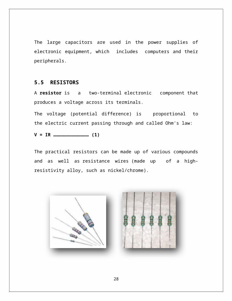
Fig . (a) Figure. (b)
Figure.14 (a), (b): RESISTORS
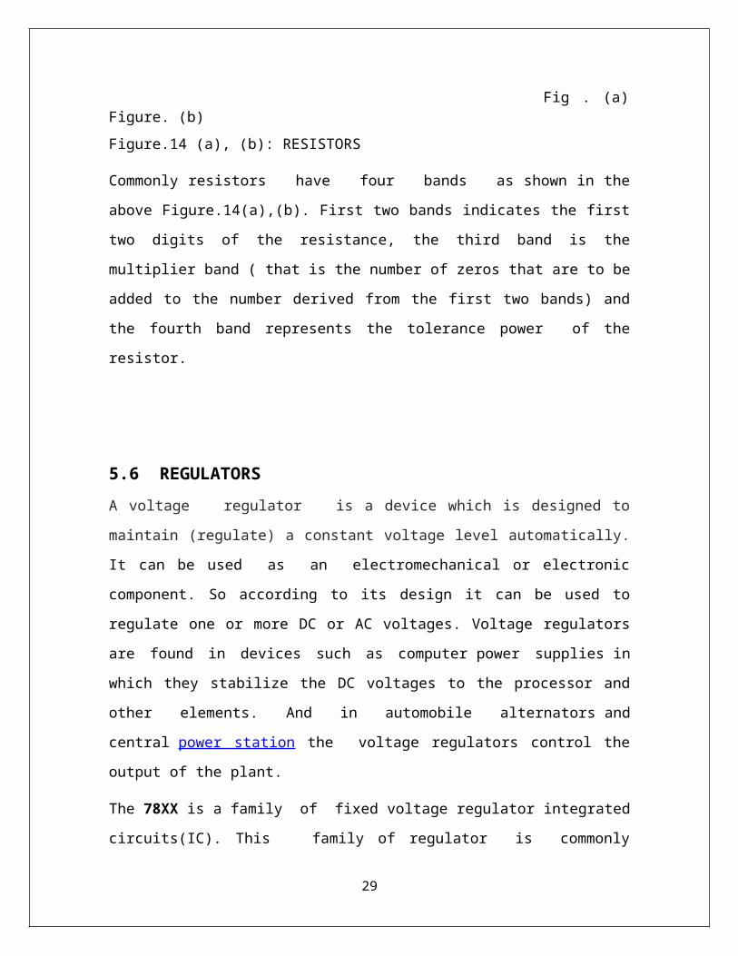
Commonly resistors have four bands as shown in the above Figure.14(a),(b). First
two bands indicates the first two digits of the resistance, the third band is the multiplier
band ( that is the number of zeros that are to be added to the number derived from the
first two bands) and the fourth band represents the tolerance power of the resistor.
5.6 REGULATORS
23

A voltage regulator is a device which is designed to maintain (regulate) a constant
voltage level automatically. It can be used as an electromechanical or electronic
component. So according to its design it can be used to regulate one or more DC or AC
voltages. Voltage regulators are found in devices such as computer power supplies in
which they stabilize the DC voltages to the processor and other elements. And in
automobile alternators and central power station the voltage regulators control the output
of the plant.
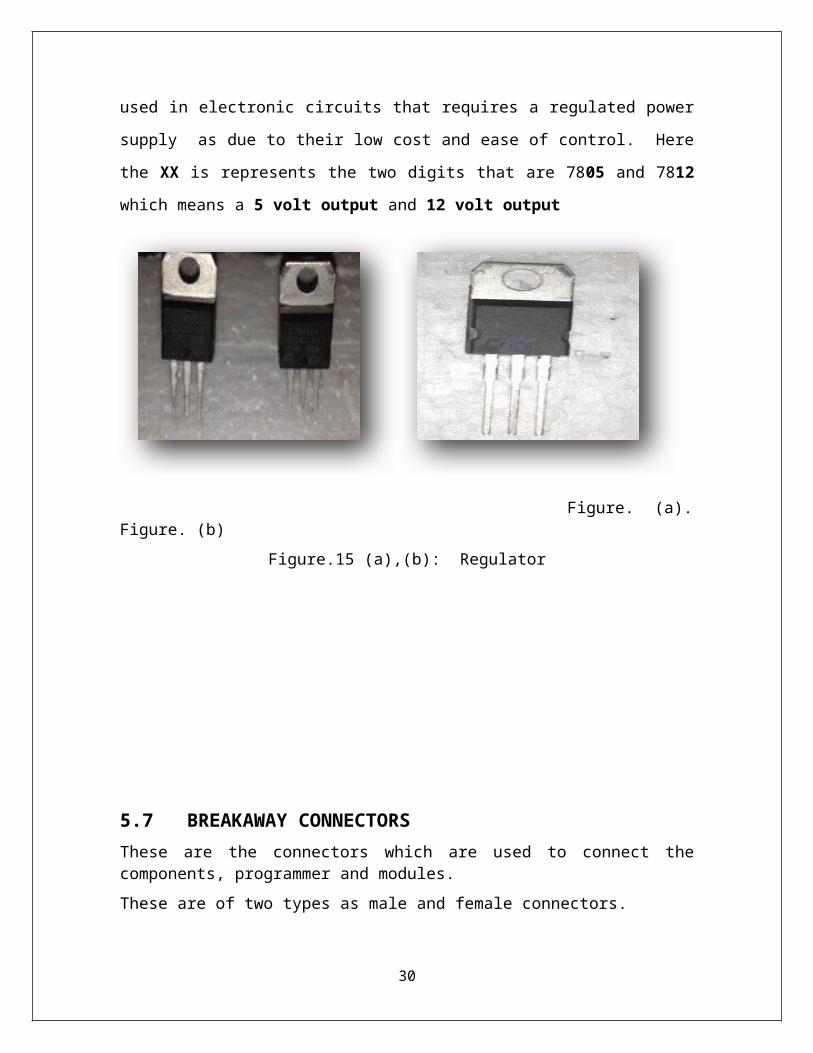
The 78XX is a family of fixed voltage regulator integrated circuits(IC). This family of
regulator is commonly used in electronic circuits that requires a regulated power
supply as due to their low cost and ease of control. Here the XX is represents the two
digits that are 7805 and 7812 which means a 5 volt output and 12 volt output
Figure. (a). Figure. (b)
Figure.15 (a),(b): Regulator
5.7 BREAKAWAY CONNECTORS
24
These are the connectors which are used to connect the components, programmer and modules.
These are of two types as male and female connectors.
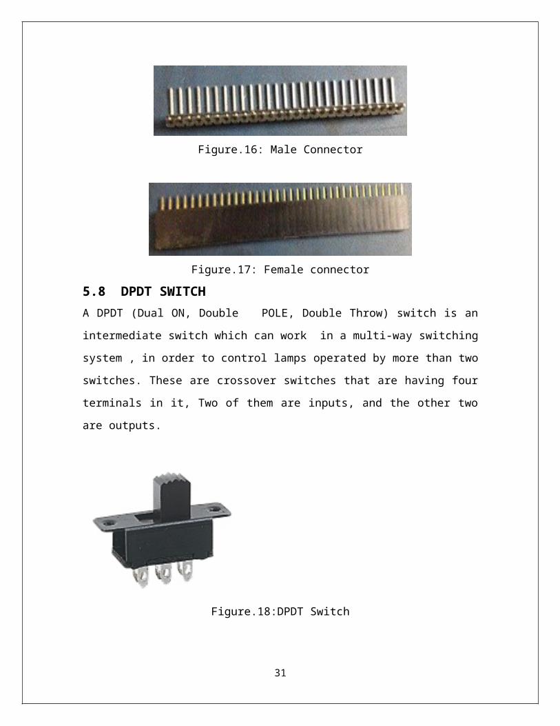
Figure.16: Male Connector
Figure.17: Female connector
5.8 DPDT SWITCH A DPDT (Dual ON, Double POLE, Double Throw) switch is an intermediate switch
which can work in a multi-way switching system , in order to control lamps operated by
more than two switches. These are crossover switches that are having four terminals in it,
Two of them are inputs, and the other two are outputs.
Figure.18:DPDT Switch
25
A more special version of the DPDT switch is that it has a third switching position in the
center which remains at ground. This can be very useful for motor control because by
virtue of which it will have three positions as Off, forward and reverse.
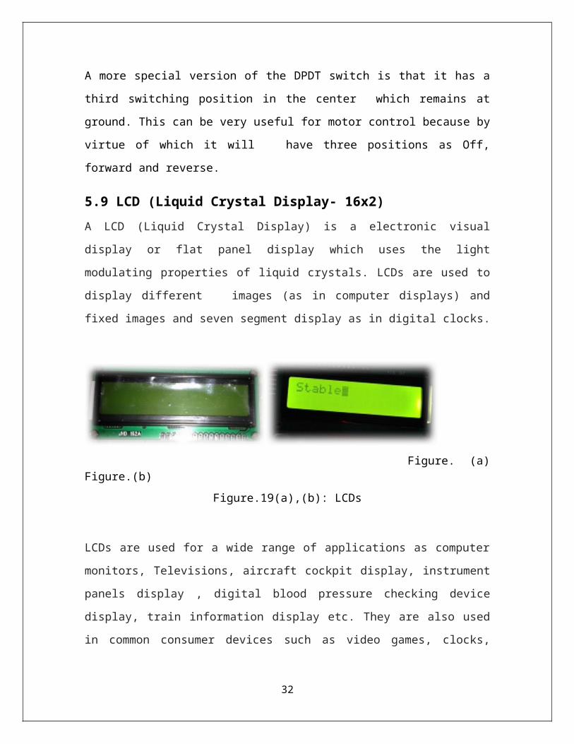
5.9 LCD (Liquid Crystal Display- 16x2)A LCD (Liquid Crystal Display) is a electronic visual display or flat panel display which
uses the light modulating properties of liquid crystals. LCDs are used to display different
images (as in computer displays) and fixed images and seven segment display as in
digital clocks.
Figure. (a) Figure.(b)
Figure.19(a),(b): LCDs
LCDs are used for a wide range of applications as computer monitors, Televisions,
aircraft cockpit display, instrument panels display , digital blood pressure checking
device display, train information display etc. They are also used in common consumer
devices such as video games, clocks, watches, telephones, mobile phones. Now a days
LED displays are available in a wider range of CRT and plasma displays.
5.10 ACCELEROMETER
An accelerometer [21][22] is a device that measures the vibration or the acceleration of
motion of a structure or body. In this the force caused by vibration or a change in motion
causes the mass to “contract” the piezoelectric material. Since the charge is proportional
to the force and the mass is a constant, then the charge is directly proportional to the
acceleration.
26
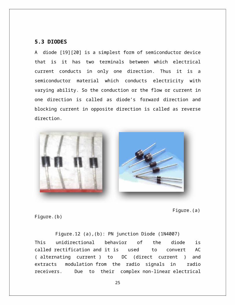
Figure.20: Accelerometer
The piezoelectric accelerometers are also called as vibration sensors and are available as
a "high impedance" charge output. In this type of accelerometer the piezoelectric crystal
produces an electrical charge which is connected directly to the measurement
instruments. This kind of accelerometer is also used for high temperature [9]
applications (>120 degree C) where low impedance models cannot be used.
27
5.11 L293D
L293D is basically a motor driver or we can say that it is a motor driver IC (Integrated
Circuit ) which allows a DC motor[23] to drive on either direction. L293D is having 16
pins which can control a set to two DC motors simultaneously in any direction (forward-
reverse). It means that we can control two DC motor with a single L293D IC.
Figure.21: L293D
Figure.22: L293D (Pin Diagram)
28

5.11.1 PIN DESCRIPTION
PinNo Various Function Name
1 Pin(Enable)- Motor ,
Active high
Enable 1,2
2 Input 1- Motor 1 Input 1
3 Output 1- Motor 1 Output 1
4 Ground (0V) Ground
5 Ground (0V) Ground
6 Output 2 - Motor 1 Output 2
7 Input 2 - Motor 1 Input 2
8 Supply voltage - Motors, +9 to +12V (up to 36V) Vcc2
9 Enable pin- Motor , Active High Enable 3,4
10 Input 1 - Motor 1 Input 3
11 Output 1- Motor 1 Output 3
12 Ground (0V) Ground
13 Ground (0V) Ground
14 Input 2- Motor 1 Output 4
15 Output2- Motor 1 Input 4
16 Supply voltage, +5V (up to 36V) Vcc1
Table 1: Pin Description ( L293D )
29
5.12 CRYSTAL
All the crystals are basically used to provide a clock input to the microprocessor (µP)
rated at 20 picofarad (pf) capacitance and +/- 50ppm stability.
Figure.23 : Crystal (Oscillator)
5.13 DC MOTOR
A electric motor [22][23] is simply a machine which converts electrical energy into
mechanical energy. A coil of wire with a current running through it, generates an
electromagnetic field which is aligned with the center of the coil.
Figure.24: DC Motors
30
The armature has the mounting bearings that keep commutator connections and power
shaft in the center of the motor. The windings in the armature loops around the
armature and uses either single or parallel wires or conductors .
The total amount of current sent to the coil and its size tells the strength of the
electromagnetic field created. In some DC motor designs the stator fields uses
electromagnets to create the magnetic fields which allows greater control over the motor.
5.14 ROBOT BODY
It is a two wheel body with two wheels attached to two DC Motors [23] to a tin chassis.
Tin chassis is a light weight sheet with high tensile strength which makes it advantageous
to use to make robot bodies. The motors used are DC Motors with specifications as
mentioned above. The wheels attached to the motors are plastic wheels which are light
and tough. These can be easily attached to the motors shaft using a plastic nut. The wheel
in the front is a castor wheel. The castor wheel is a free rotating wheel with two
dimensional degree of freedom i.e. it can move in any direction depending on the
direction of force on a plane. Below is a diagram of a robot body [6] :
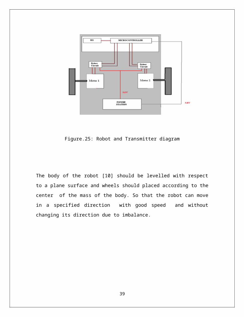
Figure.25: Robot and Transmitter diagram
31
The body of the robot [10] should be levelled with respect to a plane surface and wheels
should placed according to the center of the mass of the body. So that the robot can
move in a specified direction with good speed and without changing its direction due to
imbalance.
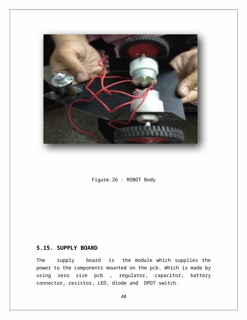
Figure.26 : ROBOT Body
32
5.15. SUPPLY BOARD
The supply board is the module which supplies the power to the components mounted on the pcb. Which is made by using zero size pcb , regulator, capacitor, battery connector, resistor, LED, diode and DPDT switch.
Figure.27 : Power Supply
Here the firstly the DPDT switch is mounted on the pcb.
Then the Diode is connected with DPDT switch and then the capacitor is mounted
on the pcb.
Then the voltage regulator is connected with the capacitor.
Then finally the LED is attached to the voltage regulator with the resistor
connected to LED in order to save it from being burst.
33
BURNING
COMPILING
CODING/ DEBUGGING
EVALUATION
CHAPTER 6. DETAILS OF COMPONENT (Software) In this section the all the details regarding project software is described.
6.1 SOFTWARE DEVELOPMENTMicrocontroller is programmed to test the hardware as well to achieve the goal of for
software development (WMSM application) , which involved the following steps as
follows.
Figure.28: Software Developments
6.2 CODING / DEBUGGING
Coding or debugging in a high-level language (such as C++, or Java). A compiler for a
high level language helps to reduce production time, in order to program the
microcontroller. The programming is done in the embedded C language. The source
code has been commented to facilitate any occasional future improvement and
maintenance.
34

AVRstudio 4.0 is a suite of open source software development and executable tool for
the Atmel AVR series of RISC microprocessors which is hosted on the platform of
Windows. It uses the GNU GCC compiler for C and C++. AVRstudio 4.0 has all the
tools for the development on the AVR. An LED will blink as soon as microcontroller’s
Flash memory is burned with the test program. Using XTU software setting on COM port
of PC zigbee(CC2500) module has been checked. The application source code is written
in embedded C language. This protocol generates the real time data. When master made
a request for the data, slave sends it back to master as soon as it gets the query. Master
displays it over the PC’s monitor.
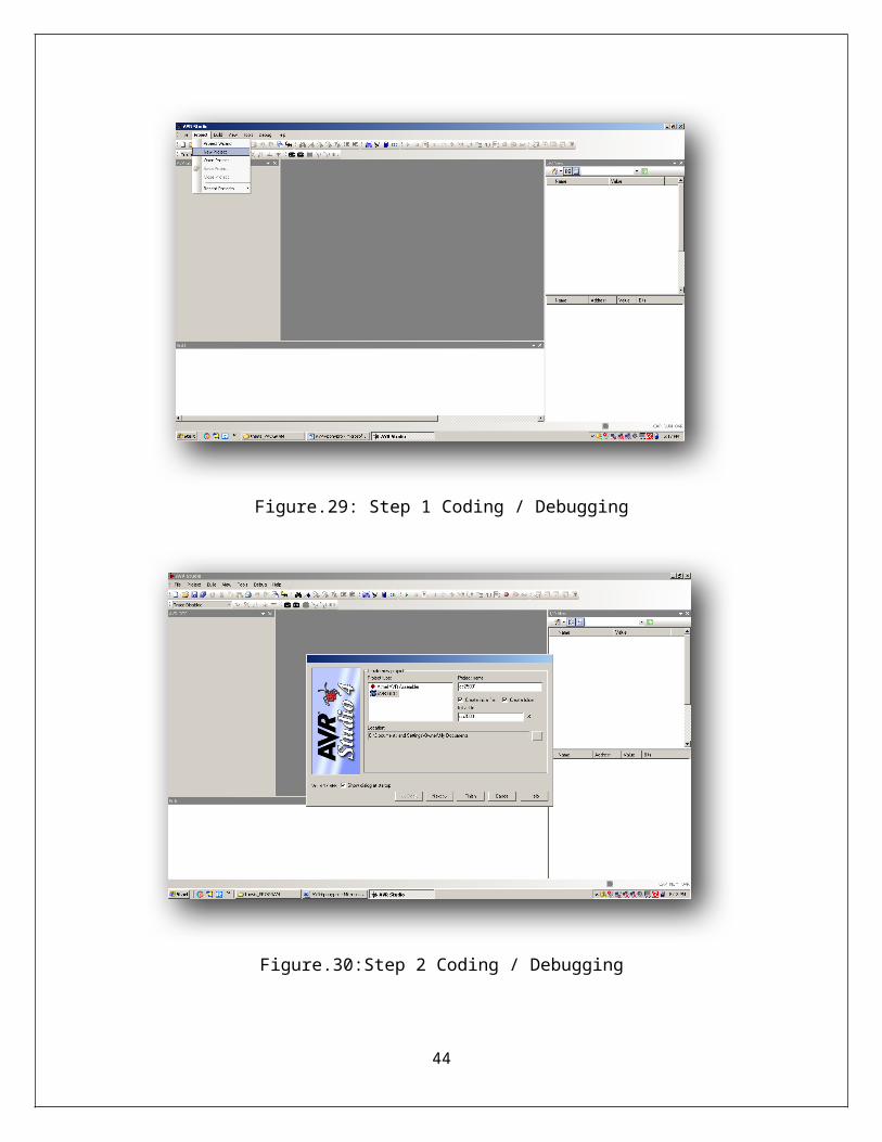
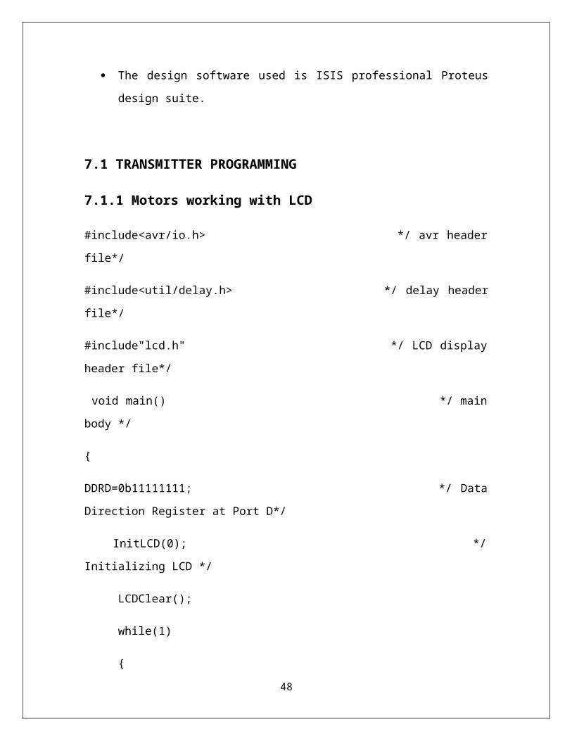
6.3 STEP BY STEP CODING OF WMSM PROGRAM
The programming of WMSM is shown in the below given figure using software AVR
Studio 4.0[3].
Figure.29: Step 1 Coding / Debugging
35
Figure.30:Step 2 Coding / Debugging
Figure.31:Step 3 Coding / Debugging
36
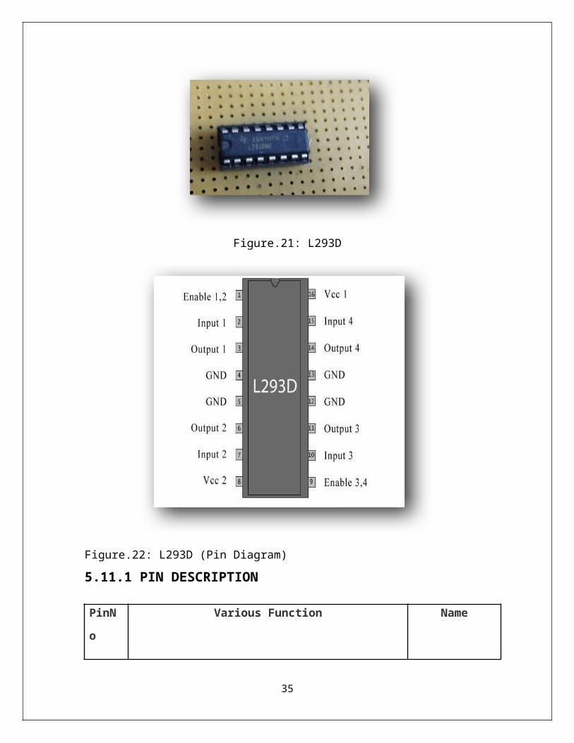
Figure.32:Step 4 Coding / Debugging
Figure.33:Step 5 Coding / Debugging
37

Figure.34: Step 6 Coding / Debugging
In this way the step for coding WMSM program has been done.
38

CHAPTER 7. PROGRAMMING
The programming has been done for transmitter module as well as for receiver
module .
The language and libraries used for the programming is embedded C.
The software used to write the programs is AVR studio 4.
The design software used is ISIS professional Proteus design suite.
7.1 TRANSMITTER PROGRAMMING
7.1.1 Motors working with LCD
#include<avr/io.h> */ avr header file*/
#include<util/delay.h> */ delay header file*/
#include"lcd.h" */ LCD display header file*/
void main() */ main body */
{
DDRD=0b11111111; */ Data Direction Register at Port D*/
InitLCD(0); */ Initializing LCD */
LCDClear();
while(1)
{
PORTD=0b11100001;
39

LCDWriteStringXY(5,1,"MOTOR1 ON ");
_delay_ms(5000); */ delay time*/
LCDClear();
PORTD=0b11100000; */ Port programming at Port D*/
LCDWriteStringXY(5,1,"MOTOR STOP "); */string text writing at LCD display*/
_delay_ms(5000);
LCDClear();
PORTD=0b11100100;
LCDWriteStringXY(5,1,"MOTOR2 ON ");
_delay_ms(5000);
LCDClear();
}
}
7.1.2 LCD programming
#include<avr/io.h>
#include<util/delay.h>
#include"lcd.h"
void main()
{
40
InitLCD(0);
while(1)
{
int i=0;
LCDClear();
LCDWriteStringXY(4,0,"LOADING");
_delay_ms(1000);
LCDClear();
LCDWriteStringXY(1,0,".");
_delay_ms(1000);
LCDWriteStringXY(2,0,".");
_delay_ms(1000);
LCDWriteStringXY(3,0,".");
_delay_ms(1000);
LCDWriteStringXY(4,0,".");
_delay_ms(1000);
LCDClear();
For (i=0; i<=100; i++)
{
LCDWriteIntXY(5,1,i,3);
41
_delay_ms(30);
}
LCDClear();
LCDWriteStringXY(4,0,"WELCOME");
_delay_ms(500);
LCDClear();
LCDWriteStringXY(6,1,"TO");
_delay_ms(500);
LCDClear();
LCDWriteStringXY(5,1,"AMITY");
_delay_ms(500);
LCDClear();
{
LCDWriteStringXY(2,1,"UNIVERSITY");
_delay_ms(100);
}
}
}
42

7.1.3 Motor bitwise operation
#include<avr/io.h>
#include<util/delay.h>
void main()
{
DDRD|=(1<<0); */ MOTOR1 */
DDRD|=(1<<1); */ MOTOR2 */
DDRD|=(1<<2); */ MOTOR3 */
DDRD|= (1<<3); */ MOTOR4 */
DDRB&=~(1<<0); */ SWITCH1 */
DDRB&=~(1<<1); */SWITCH2*/
PORTB|=(1<<0);
PORTB|=(1<<1);
while(1)
{
if((!(PINB& 1)) && (!(PINB& 2)))
{
PORTD|=(1<<0);
PORTD&=~(1<<1);
43

PORTD|=(1<<2);
PORTD&=~(1<<3);
}
else if((PINB& 1) && (!(PINB& 2)))
{
PORTD&=~(1<<0);
PORTD&=~(1<<1);
PORTD|=(1<<2);
PORTD&=~(1<<3);
}
else if((!(PINB& 1))&& (PINB& 2))
{
PORTD|=(1<<0);
PORTD&=~(1<<1);
PORTD&=~(1<<2);
PORTD&=~(1<<3);
}
else
{
PORTD&=~(1<<0);
PORTD&=~ (1<<1);
44

PORTD&=~(1<<2);
PORTD&=~(1<<3);
}
}
}
7.1.4 Programming of the transmitter module
#include<avr/io.h>
#include<util/delay.h>
#include"lcd.h"
void main()
{
MCUCSR=0x80;
MCUCSR=0x80;
USARTInit(95);
InitLCD(0);
LCDClear();
LCDWriteString("Welcome");
_delay_ms(2000);
LCDClear();
char data;
45
DDRB=0xFF;
while(1)
{
data= USARTReadChar();
if(data=='a')
{
LCDClear();
LCDWriteStringXY(0,0," Forward");
PORTB=0b00001010;
_delay_ms(10);
}
else if(data=='b')
{
LCDClear();
LCDWriteStringXY(0,0," Reverse");
PORTB=0b00000101;
_delay_ms(10);
}
else if(data=='c')
{
46

LCDClear();
LCDWriteStringXY(0,0,"Left");
PORTB=0b00001000;
_delay_ms(10);
}
else if (data=='d')
{
LCDClear();
LCDWriteStringXY(0,0," Right");
PORTB=0b00000010;
_delay_ms(10);
}
else
{
LCDClear();
LCDWriteStringXY(0,0,"Stable");
PORTB=0b00000000;
_delay_ms(10);
}
}}
47

7.1.5 Programming of the receiver module
#include<avr/io.h>
#include<util/delay.h>
#include"lcd.h"
void main()
{
MCUCSR=0x80;
MCUCSR=0x80;
USARTInit(95);
InitLCD(0);
LCDClear();
LCDWriteString("Welcome");
_delay_ms(2000);
LCDClear();
char data;
DDRB=0xFF;
while(1)
{
data= USARTReadChar();
if(data=='a')
48

{
LCDClear();
LCDWriteStringXY(0,0," Forward");
PORTB=0b00001010;
_delay_ms(10);
}
else if(data=='b')
{
LCDClear();
LCDWriteStringXY(0,0," Reverse");
PORTB=0b00000101;
_delay_ms(10);
}
else if(data=='c')
{
LCDClear();
LCDWriteStringXY(0,0," Left");
PORTB=0b00001000;
_delay_ms(10);
}
else if (data=='d')
49
{
LCDClear();
LCDWriteStringXY(0,0," Right");
PORTB=0b00000010;
_delay_ms(10);
}
else
{
LCDClear();
LCDWriteStringXY(0,0,"Stable");
PORTB=0b00000000;
_delay_ms(10);
}
}
}
50

CHAPTER 8. PROJECT DESCRIPTION
8.1 DESCRIPTION
In this section the description of whole project is described.
Firstly the power supply (receiver module) is made by using the DPDT switch,
diode, capacitor, regulator, resistor and LED (+ 3.5 Volts ).
Then the ATmega8 microcontroller is mounted on the pcb.
Then the connections are made between the supply components and
microcontroller.
After that the accelerometer is mounted on the pcb board.
Then the Zigbee (CC2500) transmitter module is connected to the
microcontroller.
After that the LCD is mounted on pcb board and connections are made with
microcontroller.
Then the receiver module is made by using microcontroller, DPDT switch, diode,
capacitor, regulator, resistor and LED.
After that the LCD is mounted on the receiver pcb board.
And the microcontroller is also attached on it
Then the Motor Driver L293D is also connected with the microcontroller.
And the Zigbee (CC2500) receiver module is also connected with the
microcontroller.
Then the BOT is made up chassis and the two DC motors are attached to it.
And the connections of the motors are made with L293D.
Then finally the receiver module is mounted on the BOT.
51
CHAPTER 9. RESULTS
In this section the results (photographs) of the working project are shown.
9.1 TRANSMITTER SECTION
Figure.35: Power Supply (Side View)
52

Figure.36: Power Supply (Top View)
Figure.37: Zigbee Module
53

Figure.38: Transmitter module
Figure.39: LCD display (Stable Direction)
54
Figure.40: LCD Display(LEFT Direction )
Figure.41: LCD Display (Forward Direction)
55

Figure. 42:LCD Display (Reverse Direction)
Figure.43: LCD Display (Right Direction)
56
9.2 RECEIVER SECTION
In this section the photographs of the receiver side modules are shown.
Figure.44: Receiver module
Figure.45: LCD Display (Stable Direction)
57

Figure.46: LCD Display( Left Direction)
Figure.47: LCD Display(Forward Direction)
58

Figure.48: LCD Display (Reverse Direction)
Figure.49: LCD Display (RIGHT Direction)
59
9.3 ADVANTAGES
This technology can be used for helping the physically challenged person.
The tilt measurement system is used in mobile phones, video games, airplanes[16]
This can be used in the field of geophysics[17].
We can use this zigbee technology for the range of 30 meters to 23 kilometers
free of cost.
9.4 LIMITATIONS
Breaking system .
Tilt measurement is not fully accurate.
9.5 CONCLUSION
The conclusion of the developed system is that the wireless module for the controlling of
the remote object or system is successfully made. Basically this system is developed for
those people who are suffering from spinal cord problem (L2,L3,L4 etc.) and are
physically challenged. According to wireless communication feature of the zigbee
protocol (IEEE 802.15.4) is done by programming the microcontroller. By developing
this kind of wireless module the use of wired system is not a limitation for it. The range
of the system depends on module to module.
9.6 FUTURE PROSPECT
As far as the future prospect is concerned this technology has enormous and
dynamic future.
This technology will be helpful for those person who are physically unable to
work on their own.
In future this technology is very useful for medical camera operations wirelessly.
60

9.7 REFERENCES
[1] Vivek kundal, Rajesh Singh, Anant wadhva, Shashank mishra “ Low cost robotics
wheel chair for disabled people in developing countries” in International Conference on
Electrical and Electronics Engineering (ICEEE), 10th March-2013, Hyderabad, ISBN:
978-93-82208-71-6
[2] Shashank Mishra, Dr. Rajesh Singh, Puneet Dobhal , Nishant Singh Bisht4 ,Upasna
Karnatak “Tilt Sensor Based Autonomous Intelligent Solar Panel Tracking System” in
Proceeding of ETPI-2013, February 15th -16th, 2013Selaqui Institute of engineering and
Technology.
[3] Bhupendra Singh, Shashank Mishra “ International e-Conference on Developments in
Computer Sciences, Electronics and Communication Technologies-2013 (e-DCSECT-
2013).
[4] Rajesh Singh, Sanjay Singh, “Wireless Traffic Control Using 2.4 GHZ ZigBee
Module” Journal of Information Technology, Listed in Ulrich's International Periodicals
Directory, USA, Volume 9: Issue 2. December 2011,ISSN No. : 0974-5513
[5] H. Şahin and L. Gűvenc, “Household Robotics: Autonomous Devices for
Vacuuming and Lawn Mowing,” IEEE Control Systems Magazine, vol. 27, no. 2,
pp. 20−96, Apr. 2007.
[6] J. Laumond, “Robot Motion Planning and Control,” Lecture Notes in Control and
Information Science 229. Berlin: Springer.
[7] W. Ren, R. W. Beard, and E. M. Atkins, “Information Consensus in Multivehicle
Cooperative Control,” IEEE Control Systems Magazine, vol. 27, no. 2, pp. 71−82,
Apr. 2007.
[8] Weiyun Jiao; Xiaojing Wang; Li Zhao; “Monitoring system of car-guardrail accident
based on wireless sensor networks” ITST – 2008 ISBN: 978-1-4244-2858-8.
[9] A.Flammini, D.Marioli, E.Sisinni, A.Taroni “A real-time wireless sensor Network for
temperature monitoring” – IEEE Transactions on Industrial Electronics 1-4244-0755-
9/07 2007.
[10] Mike Horton and John Suh “A Vision for Wireless Sensor Networks” – IEEE
transactions on Industrial Electronics 0-7803-8846-1/05, 2005.
61

[11] A. Rogers, Precision Mechatronics Lab Robot Development, M.S. thesis, Texas
A&M University, 2007.
[12] D. H. Shim, H. Chung, and S. S. Sastry, “Conflict-Free Navigation in Unknown
Urban Environments,” IEEE Robotics & Automation Magazine, vol. 13, pp. 27−33,
Sep. 2006.
[13] R. Homji, Intelligent Pothole Repair Vehicle, M.S. thesis, Texas A&M University,
2005.
[14] C. H. Kuo, H. L. Huang, and M. Y. Lee, “Development of Agent-Based
Autonomous Robotic Wheelchair Control Systems,” Journal of BiomedicalEngineering -
Applications, Basis, Communications, vol. 15, no. 6, pp. 12−23, Dec. 2003.
[15] A. Argyros, P. Georgiadis, P. Trahanias, and D. Tsakiris, “Semi-Autonomous
Navigation of a Robotic Wheelchair,” Journal of Intelligent and Robotic Systems,
vol. 34, no. 3, pp. 315−329, 2002.
[16] D. Bank, “A High-Performance Ultrasonic Sensing System for Mobile Robots,” in
ROBOTIK 2002: Leistungsstand, Anwendungen, Visionen, Trends. VDI-Berichte Nr.
1679, pp. 557−564, Jun. 2002.
[17] T. J. A. de Vries, C. v. Heteren, and L. Huttenhuis, “Modeling and Control of a Fast
Moving, Highly Maneuverable Wheelchair,” in Proceedings of the International
Biomechatronics Workshop, pp. 110−115, Apr. 1999.
[18] Jeong-Ju Kim; Chul-Ho Hong; Dong-Jin Kim; Bbun-Byul Lee; Jeong-Do Kim;
Kyung-Nam Ko “The device for generation the distress signal and monitoring system
for a Survivor based on WSN” ICEIE – 2010 ISBN: 978-1-4244- 7679-4.
[19] http://whatis.techtarget.com/definition/diode.
[20] http://www.diodes.com/
[21] http://en.wikipedia.org/wiki/Accelerometer.
[22] http://www.omega.com/prodinfo/accelerometers.html.
[23]http://www.ncert.nic.in/html/learning_basket/electricity/electricity/machine/
motor.htm.
62