hand gesture controlled robot - elementzonline · • a gesture controlled robot is a kind of robot...
TRANSCRIPT
HAND GESTURE CONTROLLED ALL TERRAIN ROBOT USING BLUETOOTH
Overview
• Introduction• Block Diagram• Hardware Requirements• Software used• Applications• References
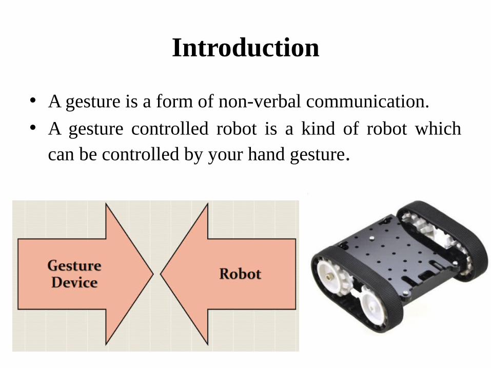
Introduction
• A gesture is a form of non-verbal communication.• A gesture controlled robot is a kind of robot which
can be controlled by your hand gesture.
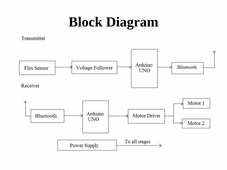
Block Diagram
Hardware requirements
• Arduino Uno • Bluetooth Module• Flex Sensor• Voltage follower• DC Motor Driver L293D• DC Motor• Power Supply

Arduino UNO
• Microcontroller board based on the ATmega328P.• 14 digital input/output pins (of which 6 can be used
as PWM outputs)• 6 analog inputs.• 16 MHz quartz crystal• A power jack• Connect it to a computer with a USB cable or
power it with a AC-to-DC adapter or battery to get started.
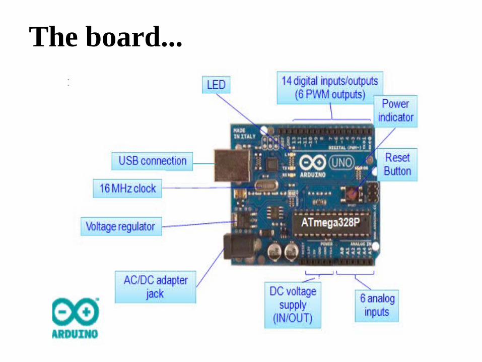
The board...
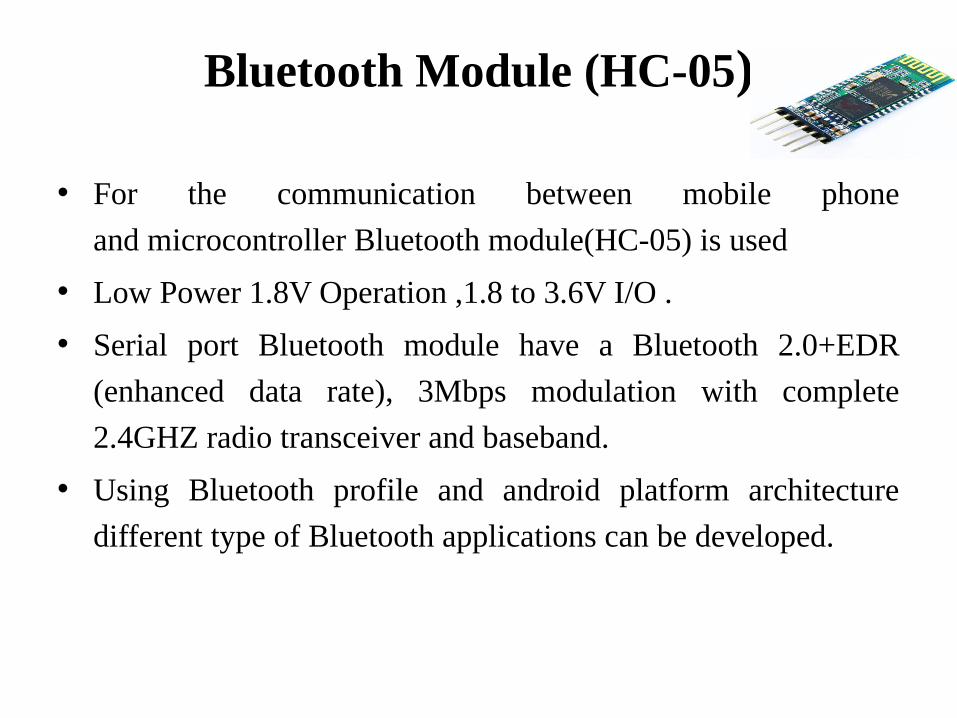
Bluetooth Module (HC-05)
• For the communication between mobile phone
and microcontroller Bluetooth module(HC-05) is used
• Low Power 1.8V Operation ,1.8 to 3.6V I/O .
• Serial port Bluetooth module have a Bluetooth 2.0+EDR
(enhanced data rate), 3Mbps modulation with complete
2.4GHZ radio transceiver and baseband.
• Using Bluetooth profile and android platform architecture
different type of Bluetooth applications can be developed.
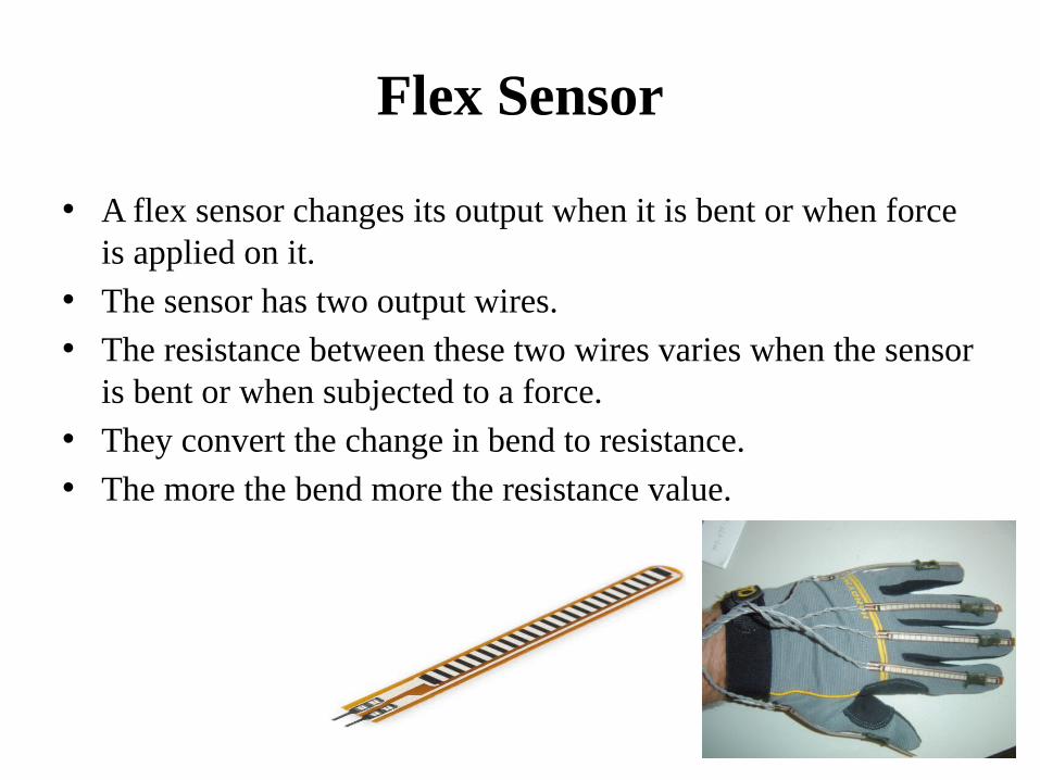
Flex Sensor
• A flex sensor changes its output when it is bent or when force is applied on it.
• The sensor has two output wires. • The resistance between these two wires varies when the sensor
is bent or when subjected to a force. • They convert the change in bend to resistance. • The more the bend more the resistance value.
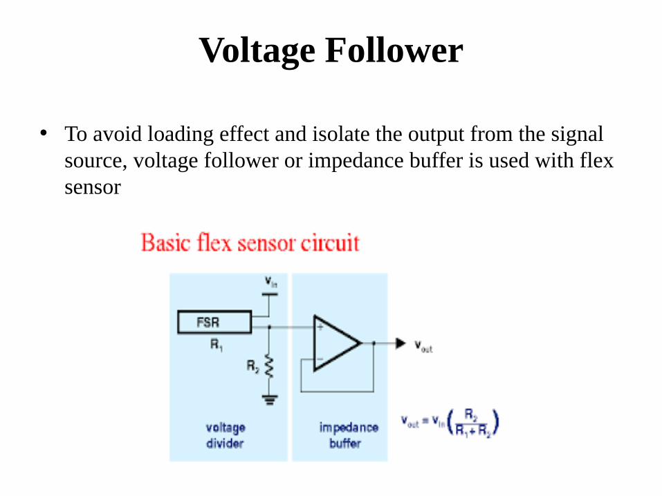
Voltage Follower
• To avoid loading effect and isolate the output from the signal source, voltage follower or impedance buffer is used with flex sensor
DC Motor Driver(L293D)
• L293D has quadruple high current half-H drivers.• Wide Supply-Voltage Range: 4.5 V to 36 V• High-Noise-Immunity Inputs• Output Current 600mA Per Channel • Peak Output Current 1.2A Per Channel.

Pin Diagram
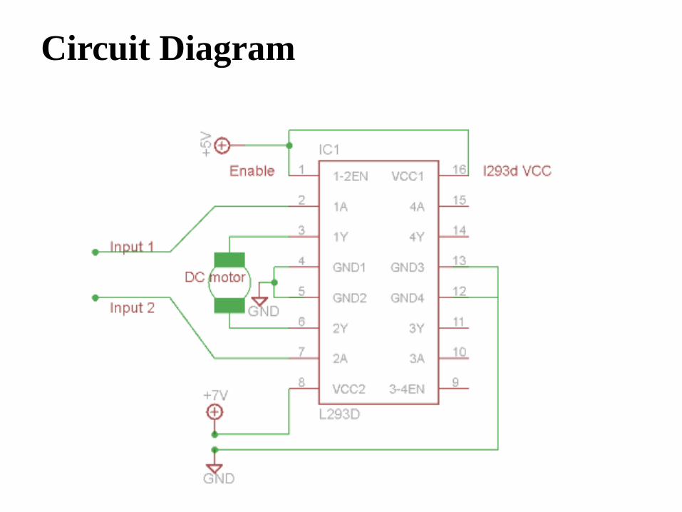
Circuit Diagram
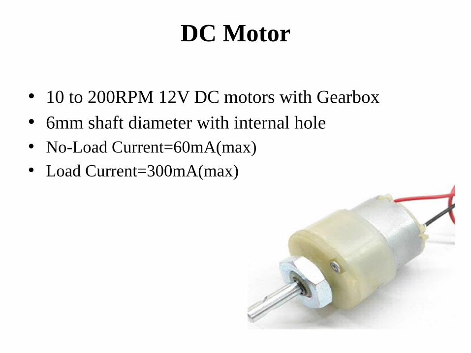
DC Motor
• 10 to 200RPM 12V DC motors with Gearbox• 6mm shaft diameter with internal hole• No-Load Current=60mA(max) • Load Current=300mA(max)
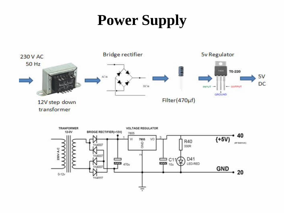
Power Supply
Software Used..
• Arduino IDE
Programming Languages Used..
• Embedded C/C++
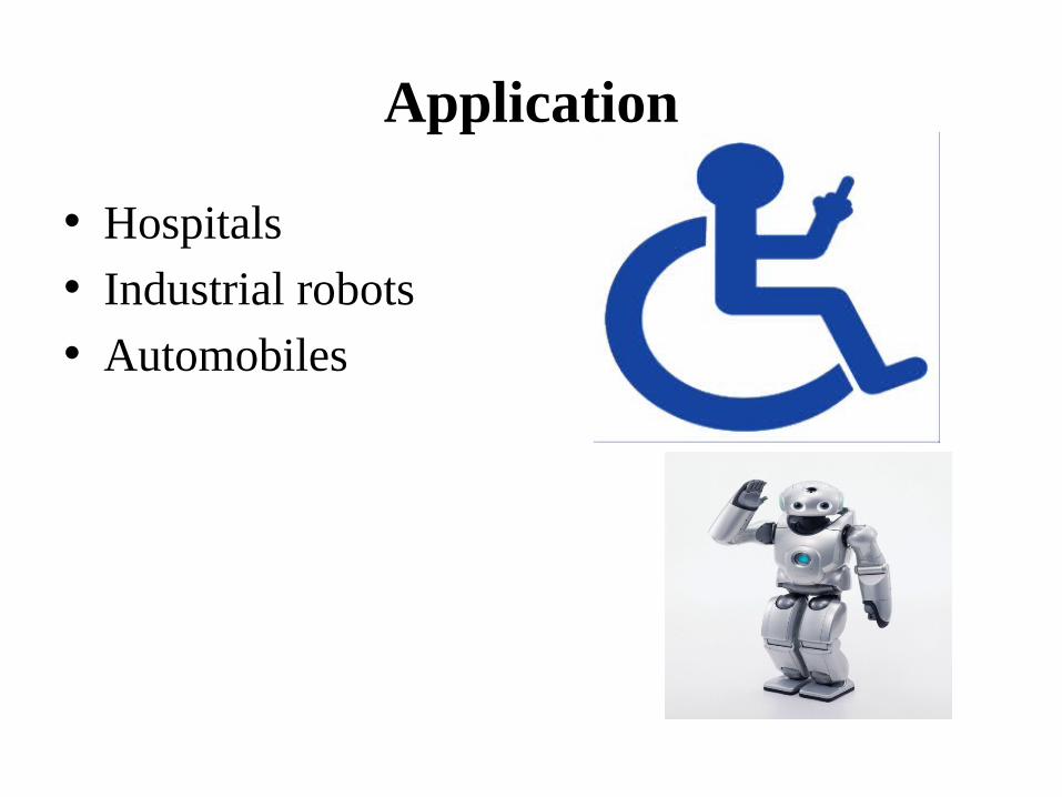
Application
• Hospitals• Industrial robots• Automobiles
References
• www.arduino.org
• www.beyondlogic.org
• www.wikipedia.org
• www.elementzonline.com
• www.elementztechblog.wordpress.com

Questions????

THANK YOU