research article thermal behavior of cylindrical buckling...
TRANSCRIPT

Research ArticleThermal Behavior of Cylindrical Buckling Restrained Braces atElevated Temperatures
Elnaz Talebi,1 Mahmood Md. Tahir,1 Farshad Zahmatkesh,1
Airil Yasreen,1 and Jahangir Mirza2
1 UTM Construction Research Centre, Universiti Teknologi Malaysia (UTM), 81310 Johor Bahru, Johor, Malaysia2 Robotics and Civil, Research Institute of Hydro-Quebec, Varennes, QC, Canada
Correspondence should be addressed to Mahmood Md. Tahir; [email protected]
Received 21 August 2013; Accepted 18 October 2013; Published 9 January 2014
Academic Editors: Y. Garbatov and R. Su
Copyright © 2014 Elnaz Talebi et al. This is an open access article distributed under the Creative Commons Attribution License,which permits unrestricted use, distribution, and reproduction in any medium, provided the original work is properly cited.
The primary focus of this investigation was to analyze sequentially coupled nonlinear thermal stress, using a three-dimensionalmodel. It wasmeant to shed light on the behavior of Buckling Restraint Brace (BRB) elements with circular cross section, at elevatedtemperature. Such bracing systems were comprised of a cylindrical steel core encased in a strong concrete-filled steel hollow casing.A debonding agent was rubbed on the core’s surface to avoid shear stress transition to the restraining system.The numerical modelwas verified by the analytical solutions developed by the other researchers. Performance of BRB system under seismic loading atambient temperature has been well documented. However, its performance in case of fire has yet to be explored.This study showedthat the failure of brace may be attributed to material strength reduction and high compressive forces, both due to temperaturerise. Furthermore, limiting temperatures in the linear behavior of steel casing and concrete in BRB element for both numerical andanalytical simulations were about 196∘C and 225∘C, respectively. Finally it is concluded that the performance of BRB at elevatedtemperatures was the same as that seen at room temperature; that is, the steel core yields prior to the restraining system.
1. Introduction
The strength of buildings in hazardous loading conditionssuch as earthquake or fire is one of the main concerns forstructural engineers. The main role of horizontal bracingsystems is to sustain wind and earthquake loads on the struc-tures. Because these systems append an additional strengthwhich prevents the formation of progressive collapse in thestructures, they can also be used to sustain forces that aregenerated in fire incidents. Previous studies [1] have shownthat horizontal bracing systems have the efficacy of not onlyenhancing the lateral restraint of the structural frame, butalso reducing the pullout of the columns, thus preventing theprogressive collapse of the structures at elevated temperature[1].
The use of Buckling Restrained Brace systems (BRBs) hasexpanded in recent decades owing to their supreme structuralbehavior in earthquakes. Performance of BRBs under staticand seismic loadings at ambient temperature [2–4] has been
well studied, while the behavior of these systems at hightemperatures has not yet been investigated to the best ofauthors’ knowledge. Hence there is a dire need to investigatethe thermal behavior of such braces at elevated temperatures.
The main role of Buckling Restrained Braced frames(BRBF) is the lateral resistance of structures in earthquakes.The principal specifications of these systems are high energydissipation capability, high ductility, and almost symmetricalhysteretic responses both in tension and compression [4]. Asshown in Figure 1, BRBs are composed of a yielding steel coreencased in a concrete-filled steel hollow casing to preventits buckling, nonyielding and buckling-restrained transitionparts, and nonyielding and unrestrained end regions. About60%–70% of the entire length of the core is restrained by thecasing [4]. In these bracing systems, compression stresses aremainly sustained by the restrained portion of the core. On theother hand, the yield strength of the steel core is much lowerthan that of steel tube casing. It allows the core to yield inthe same manner during tension and compression, prior to
Hindawi Publishing Corporatione Scientific World JournalVolume 2014, Article ID 672629, 13 pageshttp://dx.doi.org/10.1155/2014/672629

2 The Scientific World Journal
Restrained yielding segment
Restrained systemRestrained
nonyielding segmentUnrestrained
nonyielding segment
Ending Buckling restrained EndingTransitionpart
Transitionpartsegment
Figure 1: Buckling Restrained Brace (BRB) components [4].
P P
Separation gap or unbonding material
Buckling restraining mechanismSteel core
P P
Figure 2: Buckling Restrained Brace system (BRBs) [5].
the casing, thus enhancing the energy dissipation capabilitiesof BRBs considerably in comparison to the ordinary bracingsystems.
Due to Poisson’s effect on the steel core, it expandswhen itis compressed. To prevent the axial stress transition from thecore to the restrainer, a certain amount of clearance betweenthe core and concrete must be provided to avoid the frictionbetween them. To minimize the friction almost completelybetween the core and concrete, a debonding agent is appliedto the surface of the core (Figure 2).
A further detailed history of BRBs can be seen elsewhere[6].
In this study, a three-dimensional nonlinear finite ele-ment model was developed to investigate the behavior ofBRBs at elevated temperature. The nonlinear finite elementanalysis package ABAQUS [7] was utilized to perform thethermal and structural analysis. The thermal behavior ofnumericalmodel was validated by the analytical Green’s func-tion solution proposed by Wang and Tan [8]. On the otherhand, the structural responsewas validated by simulation andcomparison with the analytical model proposed by Choi andXiao [9] and Choi [10]. Using validated model, the thermalresponses of brace are shown which include the temperature-time history on the surfaces and different locations within thecross-section, as well as the structural response such as stressand strain histories of the specimen.
It is worth mentioning here that all of the notations usedin this paper are described in the Notations Section.
2. Numerical FE Model
2.1. Process of the Analysis. As mentioned above, the finiteelement analysis software, ABAQUS [7], is utilized to repre-sent the nonlinear behavior of BRBs beneath both thermaland structural actions. A sequentially-coupled thermal-stressanalysis procedure in the software is used for the modeling.This technique was utilized since stress-displacement solu-tions are affiliated to the temperature history but there isno inverse dependency [7]. This approach consisted of two
sequential analysis stages, where the outcome of first step wasused to follow the analysis in the second step. These steps areas follows.
(1) Heat Transfer Analysis. It was carried out to simulate theheat transfer from the outer surface of the brace through itscross-section and along its length.
(2) Stress Analysis. It was conducted in order to model thestructural response of BRBs exposed to fire or thermalloading resulted in Step 1.
In order to transfer thermal analysis results to thestructural analysis correctly, the type of elements must beidentical in both steps. Furthermore, the time in both ofthe steps should be consistent with each other; only then,the temperature in thermal and structural analyses has thesame meaning. Moreover, in order to prepare the conditionin which data can be transmitted more effectively betweenthe analyses, the finite element meshes should be the samein both steps.
2.2. Thermal Analysis. The thermal reaction of elementagainst heating is practically a transient heat transfer processin which the heat of fire transmits to the outer surface of thebrace by convection and radiation followed by the conductioninto the internal surfaces (i.e. steel tube, concrete casing, andsteel core) as shown in Figure 3. Convective and radiative heatfluxes can be displayed as [11]
𝑞convection = ℎV (𝑇𝑓 − 𝑇𝑠) ,
𝑞radiation = 𝜀𝑓𝜀𝑚𝜎 [(𝑇𝑓+ 𝑇0)4
− (𝑇𝑠+ 𝑇0)4
] .
(1)
For standard fire exposure, the following values are proposedby EC4 [12] for composite elements: ℎV = 25 (W/m2 K), 𝜀
𝑓=
0.8, and 𝜀𝑚= 0.7 which are used in this study. In this paper
the standard ISO 834 [13] fire curve is imposed on the exteriorsurface of the brace as a thermal loading, so as to simulate thefire through convection and radiation heat transfer processesaccording to (1) (Figure 3(a)).
In the thermal analysis, the model is meshed as three-dimensional eight-node solid element (DC3D8) for steelcore, concrete and steel casing. Despite a symmetrical cross-section of the brace and fire furnace on the exterior surfaceof the element, the whole length and entire cross-section ofthe brace is modeled in this study. This is because previousexperiments [14] had shown that in some instances thereaction of element was governed by the shear failure ofconcrete.Hence unsymmetrical deformationwas anticipated.
The results of the nonlinear heat transfer analysis consistof temperature-time history for the whole nodes withinthe 3D model. They are subsequently applied as a thermalloading to the structural model. Figure 4 compares the nodaltemperatures of BRB components as an example at the hottestposition of the brace whereas Figure 5 demonstrates thecorresponding nodal axial displacements.
2.3. Structural Analysis. A nonlinear structural model isimplemented after full thermal analysis, using the same

The Scientific World Journal 3
(a) (b)
Figure 3: (a) Heat transfer from the fire to the exposed surface of BRB by convection and radiation, (b) heat distribution from the exteriorsurface of BRB to the inner surfaces.
0100200300400500600700800900
1000
0 10 20 30 40 50 60 70Time (min)
Casing temperatureConcrete temperature
Core temperatureISO 834
Tem
pera
ture
(∘C)
Figure 4: Nodal temperatures in BRB components.
0
2
4
6
8
10
12
14
16
18
0 10 20 30 40 50 60 70
Disp
lace
men
t (m
m)
Time (min)
Casing displacementConcrete displacementCore displacement
Figure 5: Axial displacement comparison in BRB components.
finite element software [7], taking into consideration thenodal temperature-time curves previously calculated fromthe thermal analysis. The finite element meshes and nodenumberings are quite the same as those utilized in the thermalsimulation.The three-dimensional eight-node solid elements
(C3D8R) with reduced integration are used to mesh all partsof the bracing element. Two steel endplates are modeled inthe structural analysis to implement an ending boundarycondition of the steel core. The endplates are modeled asdiscrete rigid parts with all nodes coupled to a referencepoint located at the brace axis. Rigid plates are free to movealong the brace axis but fixed in other translational degrees offreedom. The rigid plates are meshed using four node three-dimensional bilinear rigid quadrilateral elements (R3D4).Figure 6 shows the three-dimensional structural model forBRB system.
As shown in Figure 6, none of the components of BRB canmove freely in the axial direction. This is due to the restraintprovided by two endings of bracing element. Temperaturerise causes elongation in the length of the brace but as theendings of the element are restrained, a big axial force isinduced in the bracing components at elevated temperature.In case of fire, it is expected that the exposed parts of thebracingmember yield first.This can be seen from Figure 6(b)which shows that the most stress is experienced in thestiffeners of steel core which are added to its exposed surfacesto prevent the yielding of this part. On the other hand, itis evident that the other exposed part of BRB, that is, steelcasing, has not yielded in the preliminary heating stages. Itcould be because in BRBs, the yield strength of steel core isintentionally established to be lower than that of steel casingwith the aim of preparing the condition that the restrainedpart of steel core yields first, under compression force. As adirect result, a part of the brace whose strength is lower (steelcore) than the other parts, yields first due to a big compressionforce formed in the BRB components at elevated temperature.This concept can be seen in Figure 6(b) which shows that ina fire the most axial stress is formed in the restrained part ofthe steel core and in the core stiffeners during primary heatingstages.
2.4. Thermal and Mechanical Contact on Concrete-Steel TubeCasing Interface. Thermal resistance at the interface betweenthe steel casing and in-filled concrete is modeled by applyinga constant value of 200W/m2K for the conductance [15].Radiation heat transfer mechanism is ignored at the cor-responding boundary because of the limited amount of airpresent in the interface void.

4 The Scientific World Journal
(a) (b)
Figure 6: (a) 3D finite element structural model for BRBs, (b) deformed shape of BRBs after exposure to standard fire.
The structural interplay between the casing and in-filledconcrete surfaces is modeled as follows.
(1) A node-to-surface formulation is utilized in the cont-act approach. The normal behavior is employed as“hard contact” formulation, in which pressure trans-mits between the surfaces only when they havecontact with each other.
(2) A Coulomb friction model is used to simulate thetangential behavior of the two contact pairs. Whenthe bond strength is higher than shear stress at theinterface, no slippage between the surfaces is noted[11]. When the two contact surfaces do have relativeslippage with each other, a friction or shear stress iscreated between them.This shear stress is determinedby the coefficient of friction and the pressure in theinterface. In this study, a constant coefficient of 0.3,which had formerly generated accurate results incontact between steel casing and in-filled concreteat room temperature simulation [15], has been used.The bond between the casing and the concrete isneglected, based on the consideration that bondstrengthmay be reduced rapidly between the surfacesat high temperatures.
2.5. Thermal and Mechanical Contact between Concrete andSteel Core Surfaces. Thermal and mechanical characteristicsof contact between the steel core and concrete are the same asthose mentioned in the previous section. The only differenceis that a constant tangential friction factor equal to 0.1 is usedfor this interface. This is because in BRB system a debondingmaterial is applied on the surface of the core so that shear isnot transferred to the restraining system.This value conformsto the friction factor between steel and rubbers.
2.6. Material Properties. For definition of material propertiesof the concrete and steel, two types of properties are needed:thermal andmechanical. For structural steel, the temperaturedependent thermal properties recommended in EC3 [16]are adopted. The thermal properties of concrete at elevated
temperature are taken fromEC2 [17].Themoisture content ofconcrete is taken into account in this study, via a maximumvalue of specific heat, which indicates the latent heat of watervaporization. According to EC4 [12], this maximum value is2020 J/kg K for a moisture content of 3% of concrete weightand 5600 J/kg K for moisture content of 10%. In this research,recommended value formoisture content of 3% is adopted forthe siliceous aggregates in concrete.
Mechanical properties ofmaterials in this analysis includeelastic and plastic characteristics and coefficient of thermalexpansion. Elastic modulus and Poisson’s ratio are twoprincipal parameters for elastic behavior. In the ABAQUSpackage [7], a classicmetalmaterial model is selected for steelnonlinearity which follows Von Misses’ yield function andassociated plastic flow rule [1]. Steel mechanical temperature-dependent values are adopted as recommended in EC3 [16].
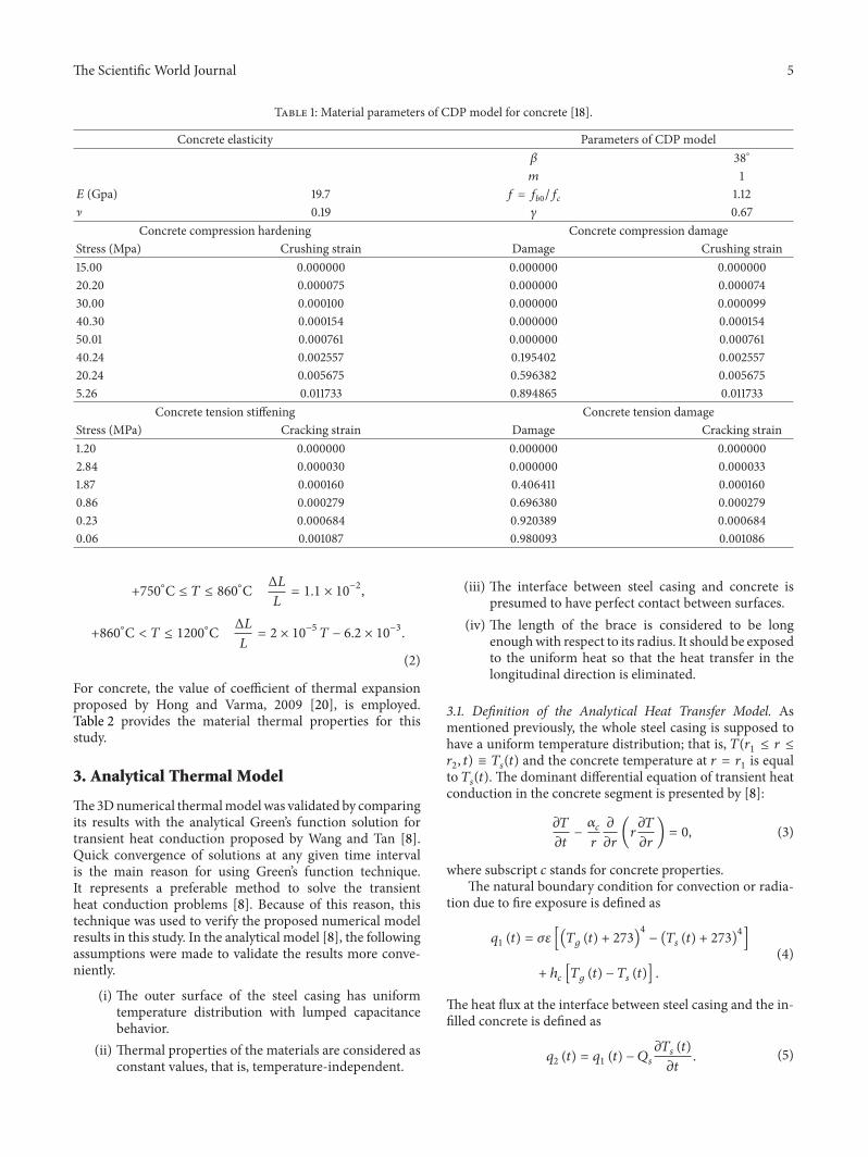
A concrete damaged plasticity model (CDP) in ABAQUS[7] is utilized for the fundamental relationship of concrete.This model applies the significance of isotropic damagedplasticity to demonstrate the nonlinear behavior of con-crete. It also contains the combination of nonassociatedmultihardening plasticity and isotropic damaged elasticity todemonstrate the irreversible damage which occurs throughfracturing [11]. Concrete has multiple behaviors and damagemechanisms under compression and tension. Therefore, thestress-strain relationships for concrete need to be specifiedboth in tension and compression. There are several optionsto define the tensile stress-strain relationship in the concretedamaged plasticity model. Tensile characteristic of concreteat elevated temperature is specified as traditional tensilestress-strain relationship that exists in the concrete damagedplasticity model as described in ABAQUS [7]. For modelingdamaged plasticity in concrete, the relevant values proposedby Jankowiak [18] are adopted and presented in Table 1.
Since Euro code 3 does not provide the coefficient ofthermal expansion, 𝛼 precisely, it can be computed as the firstderivative of the equations proposed for thermal strains ofcarbon steel, with the following result [19]:
+20∘C ≤ 𝑇 < 750
∘C Δ𝐿
𝐿=1.2 × 10
−5
𝑇 + 0.4 × 10⁻⁸
𝑇2
− 2.41 × 10⁻⁴
,
The Scientific World Journal 5
Table 1: Material parameters of CDP model for concrete [18].
Concrete elasticity Parameters of CDP model𝛽 38
∘
𝑚 1𝐸 (Gpa) 19.7 𝑓 = 𝑓
𝑏0
/𝑓𝑐
1.12] 0.19 𝛾 0.67
Concrete compression hardening Concrete compression damageStress (Mpa) Crushing strain Damage Crushing strain15.00 0.000000 0.000000 0.00000020.20 0.000075 0.000000 0.00007430.00 0.000100 0.000000 0.00009940.30 0.000154 0.000000 0.00015450.01 0.000761 0.000000 0.00076140.24 0.002557 0.195402 0.00255720.24 0.005675 0.596382 0.0056755.26 0.011733 0.894865 0.011733
Concrete tension stiffening Concrete tension damageStress (MPa) Cracking strain Damage Cracking strain1.20 0.000000 0.000000 0.0000002.84 0.000030 0.000000 0.0000331.87 0.000160 0.406411 0.0001600.86 0.000279 0.696380 0.0002790.23 0.000684 0.920389 0.0006840.06 0.001087 0.980093 0.001086
+750∘C ≤ 𝑇 ≤ 860
∘C Δ𝐿
𝐿= 1.1 × 10
−2
,
+860∘C < 𝑇 ≤ 1200
∘C Δ𝐿
𝐿= 2 × 10
−5
𝑇 − 6.2 × 10⁻³
.
(2)
For concrete, the value of coefficient of thermal expansionproposed by Hong and Varma, 2009 [20], is employed.Table 2 provides the material thermal properties for thisstudy.
3. Analytical Thermal Model
The3Dnumerical thermalmodelwas validated by comparingits results with the analytical Green’s function solution fortransient heat conduction proposed by Wang and Tan [8].Quick convergence of solutions at any given time intervalis the main reason for using Green’s function technique.It represents a preferable method to solve the transientheat conduction problems [8]. Because of this reason, thistechnique was used to verify the proposed numerical modelresults in this study. In the analytical model [8], the followingassumptions were made to validate the results more conve-niently.
(i) The outer surface of the steel casing has uniformtemperature distribution with lumped capacitancebehavior.
(ii) Thermal properties of the materials are considered asconstant values, that is, temperature-independent.
(iii) The interface between steel casing and concrete ispresumed to have perfect contact between surfaces.
(iv) The length of the brace is considered to be longenoughwith respect to its radius. It should be exposedto the uniform heat so that the heat transfer in thelongitudinal direction is eliminated.
3.1. Definition of the Analytical Heat Transfer Model. Asmentioned previously, the whole steel casing is supposed tohave a uniform temperature distribution; that is, 𝑇(𝑟
1≤ 𝑟 ≤
𝑟2, 𝑡) ≡ 𝑇
𝑠(𝑡) and the concrete temperature at 𝑟 = 𝑟
1is equal
to 𝑇𝑠(𝑡). The dominant differential equation of transient heat
conduction in the concrete segment is presented by [8]:
𝜕𝑇
𝜕𝑡−𝛼𝑐
𝑟
𝜕
𝜕𝑟(𝑟
𝜕𝑇
𝜕𝑟) = 0, (3)
where subscript 𝑐 stands for concrete properties.The natural boundary condition for convection or radia-
tion due to fire exposure is defined as
𝑞1(𝑡) = 𝜎𝜀 [(𝑇
𝑔(𝑡) + 273)
4
− (𝑇𝑠(𝑡) + 273)
4
]
+ ℎ𝑐[𝑇𝑔(𝑡) − 𝑇
𝑠(𝑡)] .
(4)
The heat flux at the interface between steel casing and the in-filled concrete is defined as
𝑞2(𝑡) = 𝑞
1(𝑡) − 𝑄
𝑠
𝜕𝑇𝑠(𝑡)
𝜕𝑡. (5)

6 The Scientific World Journal
Table 2: Thermal properties of steel and concrete at elevated temperature.
Temperature Thermal expansion (×10−6) Thermal conductivity (J/S-m-∘C) Specific Heat (×10−2)Concrete Steel Concrete Steel Concrete Steel
20 6.00 12.16 1.45 53.30 9.00 4.40100 6.80 12.80 1.35 50.70 9.00 4.88200 7.60 13.60 1.33 47.30 20.20 5.30300 8.40 14.40 1.22 44.00 10.00 5.65400 9.20 15.20 1.10 40.70 10.50 6.06410 9.30 16.00 0.99 37.40 11.00 6.67445 9.60 16.80 0.89 34.00 11.00 7.60500 10.00 17.60 0.80 30.70 11.00 10.08600 10.80 0.00 0.72 29.50 11.00 50.00635 11.10 20.00 0.67 27.30 11.00 8.03700 11.60 20.00 0.63 27.30 11.00 6.50715 11.70 20.00 0.60 27.30 11.00 6.50785 12.30 20.00 0.57 27.30 11.00 6.50800 12.40 12.16 0.55 27.30 11.00 6.50900 13.20 12.80 1.45 53.30 9.00 4.401000 14.00 13.60 1.35 50.70 9.00 4.881100 14.80 14.40 1.33 47.30 20.20 5.301200 15.60 15.20 1.22 44.00 10.00 5.65
3.2. Impulse Green’s Function. By applying the eigenfunctionconcept, the impulse Green’s function can be expressed as [8]:
𝑔 (𝑟, 𝑡 − 𝜏)
=2𝛼𝑐
𝑘𝑐𝑟0
× [1 +
∞
∑
𝑛=1
1
𝐽0(𝜁𝑛)
𝑒−𝛼𝑐𝜁
2
𝑛(𝑡−𝜏)
𝑟20
𝐽0(𝜁𝑛
𝑟
𝑟0
)] .
(6)
As the impulse Green’s functions are for the homogeneoussystems, some feasible singularitiesmay occur at 𝑡 = 𝜏 and 𝑟 =𝜉 = 𝑟1due toDirac delta functionswhich represented the unit
heat impulse [8]. To prevent the corresponding singularitiesof the impulse Green’s functions 𝑔(𝑟, 𝑡 − 𝜏), the temporaryintegral forms of 𝑔, called the step Green’s functions, are usedinstead.
3.3. Step Green’s Function. The step Green’s function is imple-mented to solve the heat transfer equations as follows [8]:
𝐺 (𝑟, 𝑡) = ∫
𝑡
𝜏=0
𝑔 (𝑟, 𝑡 − 𝜏) 𝑑𝜏 =2𝛼𝑐𝑡
𝑘𝑐𝑟0
+
∞
∑
𝑛=1
𝐶𝑛× 𝐽0(𝜁𝑛
𝑟
𝑟0
)(1 − 𝑒−𝛼𝑐𝜁2
𝑛
𝑡
𝑟20
) ,
(7)
where the coefficient 𝐶𝑛is given by
𝐶𝑛=
2𝑟0
𝑘𝑐𝜁2𝑛
𝐽0(𝜁𝑛). (8)
3.4. Insertion of Fire Environment (Duhamel’s Principle). Inthe previous section the heat transfer model and its solutionwere discussed (formore details, see [8]). Duhamel’s principledisplays a strong technique to deal with time-dependentproblems in fire conditions as [8]:
𝜃 (𝑟1, 𝑡) = 𝜃
𝑠(𝑡) = ∫
𝑡
𝜏=0
𝑞2(𝑡 − 𝜏) 𝑑𝐹 (𝜏) . (9)
Let 𝜃(𝑟, 𝑡) = 𝑇(𝑟, 𝑡)−𝑇0represent the normalized temperature
field. The flux condition at the interface between the steelcasing and concrete is given by
𝑞2(𝑡) = 𝑞
1(𝑡) − 𝑄
𝑠
𝜃𝑠(𝑡) , (10)
where 𝜃𝑠(𝑡) = 𝜕𝜃
𝑠(𝑡)/𝜕𝑡, with the overhead dot signifying the
timederivative, and 𝑞1(𝑡) is achieved at the fire exposure (with
convection and conduction boundary conditions) accordingto (4).
For solving (9), we started with the numerical layouts byfirst discretizing the time interval as follows:
{𝑡𝑛= 𝑛Δ𝑡, 𝑛 = 0, 1, 2, . . . , 𝑁}, where Δ𝑡 is the constant
sampling time [8].Consider the following:
𝜃𝑠(𝑛)=∫
𝑡
𝜏=0
𝜃𝑠(𝜏) 𝑑𝜏=[
[
1
2
𝜃𝑠(0)+
𝑛−1
∑
𝑗=1
𝜃𝑠(𝑗)+
1
2
𝜃𝑠(𝑛)]
]
×Δ𝑡
𝜃𝑠(𝑛) =
[𝐵 (𝑛) − 𝐶 (𝑛)]
𝐴,
(11)where
𝐴 =1
2Δ𝑡 +
1
2𝑄𝑠Δ𝐹 (1) ,
𝐵 (𝑛) =1
2Δ𝐹1𝑞1(𝑛) + 𝑆
𝑛(𝑞1, Δ𝐹) ,
𝐶𝑛= 𝑄𝑠𝑆𝑛( 𝜃𝑠, Δ𝐹) +
1
2
𝜃𝑠(0) Δ𝑡 +
𝑛−1
∑
𝑗=1
𝜃𝑠(𝑗) Δ𝑡,
𝑆𝑛(𝜐, Δ𝐹) =
1
2𝜐 (𝑛 − 1) Δ𝐹 (1)
+1
2
𝑛
∑
𝑗=2
[𝜐 (𝑛 − 𝑗 + 1) + 𝜐 (𝑛 − 𝑗)] × Δ𝐹 (𝑗) .
(12)

The Scientific World Journal 7
12
3
4
Steel casing outer surface
Steel tube and concrete interface
Concrete casing middle section
Steel core and concrete interface
1
2
3
4
Figure 7: Different locations of bracing elements for temperaturepredictions.
In order to use the above mentioned equations perfectly,Wang and Tan [8] outlined the use of Green’s functionsolutions step by step.
4. Verification of Numerical Heat TransferModel with Analytical Thermal Model
In the analytical model [8], temperature-independent ther-mal properties of concrete and steel are given as
𝑘𝑠= 45W/mk, C
𝑠= 600 J/kgK, 𝜌
𝑠= 7850 kg/m3,
𝑘𝑐= 1.6W/mk, C
𝑐= 1000 J/kgK, 𝜌
𝑐= 2400 kg/m3.
(13)
Also in the analytical model, the existence of moisturecontent in concrete part was not taken into considerationfor simplicity. The temperature-time responses (𝑇-𝑡 Curves)at different locations of bracing section (Figure 7) are com-pared in both analysis procedures (Figures 8, 9, 10, and 11).The values in these figures show that the temperature-timehistories, derived from numerical model in every locationof BRB section, are in good agreement with the analyticalsolution prediction. Some discrepancies between the resultsare predicted by the analytical equations [8] and the proposedFE analysis. This could be due to some previously mentionedassumptions that were considered in the analytical solutionfor simplicity.
It is worth mentioning here that the results of the pro-posed FEmodel are in close agreement with the experimentalwork on the behavior of BRBwith square cross section in caseof fire. This work was carried out by Saitoh et al., 2005 [21].
0100200300400500600700800900
1000
0 10 20 30 40 50 60 70Time (min)
Numerical resultAnalytical resultISO 834
Tem
pera
ture
(∘C)
Figure 8: Comparison of 𝑇-𝑡 Curves at point 1.
Numerical resultAnalytical resultISO 834
0100200300400500600700800900
1000
0 10 20 30 40 50 60 70Time (min)
Tem
pera
ture
(∘C)
Figure 9: Comparison of 𝑇-𝑡 Curves at point 2.
0100200300400500600700800900
1000
0 10 20 30 40 50 60 70Time (min)
Numerical resultAnalytical resultISO 834
Tem
pera
ture
(∘C)
Figure 10: Comparison of 𝑇-𝑡 Curves at point 3.

8 The Scientific World Journal
0 10 20 30 40 50 60 70Time (min)
Numerical resultAnalytical resultISO 834
0100200300400500600700800900
1000
Tem
pera
ture
(∘C)
Figure 11: Comparison of 𝑇-𝑡 Curves at point 4.
5. Analytical Structural Model
5.1. Theory and Assumption. The proposed FE model forthe structural behavior of BRB under axial force due totemperature rise was validated by the analytical model pro-posed by Choi and Xiao [9]. This study predicted lateralinteraction between concrete and steel casing in compression.In the analytical model [9], it was assumed that each segmentsupported the stress only from the axial direction with nostress from the other directions. Furthermore, the concretesurface and the steel casing internal surface have a completecontact between themat room temperature; that is, there is nogap between the concrete and tube at room temperature. Atelevated temperature; on the other hand, the cross-sectionalinteraction between them is such that the gap is developedbetween steel casing and in-filled concrete during axialthermal loading. This is because the coefficient of thermalexpansion of concrete is less than steel. Hence, the steelcasing expands more than concrete laterally and creates a gapat the interface. In this state, the steel casing and in-filledconcrete deformations are similar as in uniaxial loading ofeach specimen. So both materials will be deformed withoutany interaction. As mentioned earlier that in BRB there isan initial gap between the outer surface of the core and theconcrete; thus the steel core deformation is also in uniaxialloading mode and without any interaction with the concrete.It is worth mentioning here that the bond stress at the steelcasing and in-filled concrete interface is assumed to be zero.
5.2. Equilibrium Condition. Figure 12 displays the cylindricalcoordinate system of the BRB system in the equilibrium state.In the equilibrium equations, the 𝑟-direction and 𝜃-directionstresses of the steel core and the concrete are equal. As perrelationship between steel tube and concrete, the equilibriumconditions can be described by the following [9]:
𝑓𝑟𝑐= 𝑓𝜃𝑐,
2𝑡𝑡× 𝑓𝜃𝑡= −𝑓𝑟𝑐(𝐷𝑡− 2𝑡𝑡) ,
(14)
where subscripts 𝑐, 𝑡, and co denote concrete, steel tube,and core, respectively. At elevated temperatures, the axialcompression force in the bracing element can be representedas
𝑃th = 𝐸𝐴𝛼 ⋅ Δ𝜃. (15)
In case the gap between steel tube and concrete interfacedoes not exist at room temperature, 𝜃-direction strain valuesshould be the same between them. Also the 𝑟-direction and𝜃-direction strains of concrete and core remain identical.Hence, the deformation relationships can be expressed as [9]:
𝑟-𝜃 direction: 𝜀𝑟𝑐= 𝜀𝜃𝑐,
𝑟-𝜃 direction: 𝜀𝑟co = 𝜀
𝜃co,
𝜃 direction: 𝜀𝜃𝑐= 𝜀𝜃𝑡.
(16)
5.3. Constitutive Model
5.3.1. Constitutive Model for Steel Tube Casing. In the steelcasing, the stress-strain relationship can be displayed byHooke’s law under biaxial stress as [9]:
{𝑓𝑧𝑡
𝑓𝜃𝑡
} =𝐸𝑠
1 − 𝜐2𝑡
[1 ]𝑡
]𝑡1] {
𝜀𝑧𝑡
𝜀𝜃𝑡
} , (17)
where 𝑓𝑧𝑡
and 𝑓𝜃𝑡
are axial and tangential forces, and 𝜀𝑧𝑡
and 𝜀𝜃𝑡represent axial and tangential strains in the steel tube
casing, respectively.
5.3.2. Constitutive Model for Concrete. The concrete model isbased on octahedral normal and shear stress-strain relation-ships, which can be defined by the following [9]:
𝜎oct =1
3(𝑓𝑧+ 𝑓𝑟+ 𝑓𝜃) ,
𝜏oct =1
3
√(𝑓𝑧− 𝑓𝑟)2
+ (𝑓𝑟− 𝑓𝜃)2
+ (𝑓𝜃− 𝑓𝑧)2
,
𝜀oct =1
3(𝜀𝑧+ 𝜀𝑟+ 𝜀𝜃) ,
𝛾oct =2
3
√(𝜀𝑧− 𝜀𝑟)2
+ (𝜀𝑟− 𝜀𝜃)2
+ (𝜀𝜃− 𝜀𝑧)2
,
(18)
where 𝜎oct and 𝜏oct are octahedral normal and shear stressesand 𝜀oct and 𝛾oct are octahedral normal and shear strains,respectively.
5.3.3. ConstitutiveModel for Steel Core. The stress-strain rela-tionship of steel core for the elastic range can be representedby the following Hooke’s law under three-axial stress:
{{
{{
{
𝑓𝑧co𝑓𝑟co𝑓𝜃co
}}
}}
}
=𝐸𝑐
(1 + 𝜐co) (1 − 2𝜐co)
× [
[
1 − 𝜐co 𝜐co 𝜐co𝜐co 1 − 𝜐co 𝜐co𝜐co 𝜐co 1 − 𝜐co
]
]
{{
{{
{
𝜀𝑧co𝜀𝑟co𝜀𝜃co
}}
}}
}
,
(19)
where 𝑓𝑧co, 𝑓𝑟co, and 𝑓
𝜃co are axial, radial and tangentialstresses and 𝜀
𝑧co, 𝜀𝑟co, and 𝜀𝜃co are axial, radial, and tangentialstrains in the steel core, respectively.

The Scientific World Journal 9
Filled-in concrete Steel core
Steel tube
P
P
frt
fzt
fzt
f𝜃tf𝜃t f𝜃t
f𝜃t
fz
L/2
frco
frco
frc
frc
Figure 12: Equilibrium relationship between BRB components.
6. Verification of Numerical StructuralAnalysis with Analytical Model
The numerical structural model was validated by comparingthe results with the analytical solution for composite elementssubjected to axial compression force, as proposed byChoi andXiao [9]. In this comparison, the elastic range of materialsis discussed with an initial gap between the steel core andconcrete aswell as a gap generated between themduring load-ing at elevated temperatures. The adequacy of the numericalresults developed by the authors was verified by comparingwith the results of existing analytical structural formulations[9] (Figures 13–24).
6.1. Verification of Core Results. In the analytical simulation,the stress in 𝑟-𝜃 directionwas set to zero.This is because of theexistence of initial gap between steel core and concrete in theBRB system. Figures 13, 14, 15, and 16 compare the stresses andstrains, resulting in both analytical and proposed numericalmodels.
6.2. Verification of Filled-In Concrete Results. Because of thegenerated gap between steel casing and concrete at elevatedtemperature, the radial and tangential stresses between themin the restraining system were set to zero value in theanalytical model. Figures 17, 18, 19, and 20 compare the stressand strain results in both procedures. The data showed thatthe proposed numerical FE model results are generally ingood agreement with the analytical results.
6.3. Verification of Steel Casing Results in Restraining System.Figures 21, 22, 23, and 24 compare the stress and strain curvesfor both procedures in the steel tube casing. Close agreementwith the analytical and numerical results in the behavior ofsteel casing at elevated temperature was observed. In the steeltube, the radial strain value is near zero, so its thickness isnegligible in comparison to its other dimensions. Thus in
0 10 20 30 40 50 60 70
Numerical resultAnalytical result
Axi
al st
ress
(kN
/m2)
0.0E + 00
5.0E + 04
1.0E + 05
1.5E + 05
2.0E + 05
2.5E + 05
3.0E + 05
3.5E + 05
Temperature (∘C)
Figure 13: Comparison of axial stress in steel core.
0.0E + 00
2.0E − 04
4.0E − 04
6.0E − 04
8.0E − 04
1.0E − 03
1.2E − 03
1.4E − 03
1.6E − 03
1.8E − 03
0 20 40 60 80 100 120 140
Axi
al st
rain
Numerical resultAnalytical result
Temperature (∘C)
Figure 14: Comparison of axial strain in steel core.
0.0E + 005.0E − 051.0E − 041.5E − 042.0E − 042.5E − 043.0E − 043.5E − 044.0E − 044.5E − 045.0E − 04
0 20 40 60 80 100 120 140
Radi
al st
rain
Numerical resultAnalytical result
Temperature (∘C)
Figure 15: Comparison of radial strain in steel core.

10 The Scientific World Journal
0.0E + 005.0E − 051.0E − 041.5E − 042.0E − 042.5E − 043.0E − 043.5E − 044.0E − 044.5E − 045.0E − 04
0 20 40 60 80 100 120 140
Tang
entia
l Str
ain
Numerical resultAnalytical result
Temperature (∘C)
Figure 16: Comparison of tangential strain in steel core.
0.0E + 00
2.0E + 03
4.0E + 03
6.0E + 03
8.0E + 03
1.0E + 04
1.2E + 04
1.4E + 04
1.6E + 04
1.8E + 04
0 20 40 60 80 100 120 140
Numerical resultAnalytical result
Axi
al st
ress
(kN
/m2)
Temperature (∘C)
Figure 17: Comparison of axial stress in concrete.
0.0E + 00
1.0E − 04
2.0E − 04
3.0E − 04
4.0E − 04
5.0E − 04
6.0E − 04
7.0E − 04
8.0E − 04
9.0E − 04
Axi
al st
rain
0 20 40 60 80 100 120 140
Numerical resultAnalytical result
Temperature (∘C)
Figure 18: Comparison of axial strain in concrete.
0.0E + 00
2.0E − 05
4.0E − 05
6.0E − 05
8.0E − 05
1.0E − 04
1.2E − 04
1.4E − 04
Radi
al st
rain
0 20 40 60 80 100 120 140
Numerical resultAnalytical result
Temperature (∘C)
Figure 19: Comparison of radial strain in concrete.
0.0E + 00
2.0E − 05
4.0E − 05
6.0E − 05
8.0E − 05
1.0E − 04
1.2E − 04
1.4E − 04
1.6E − 04
1.8E − 04Ta
ngen
tial s
trai
n
0 20 40 60 80 100 120 140
Numerical resultAnalytical result
Temperature (∘C)
Figure 20: Comparison of tangential strain in concrete.
0.0E + 00
5.0E + 04
1.0E + 05
1.5E + 05
2.0E + 05
2.5E + 05
3.0E + 05
3.5E + 05
0 20 40 60 80 100 120 140
Numerical resultAnalytical result
Temperature (∘C)
Axi
al st
ress
(kn/
m2)
Figure 21: Comparison of axial stress in steel tube casing.

The Scientific World Journal 11
0.0E + 00
2.0E − 04
4.0E − 04
6.0E − 04
8.0E − 04
1.0E − 03
1.2E − 03
1.4E − 03
1.6E − 03
1.8E − 03
Axi
al st
rain
0 20 40 60 80 100 120 140
Numerical resultAnalytical result
Temperature (∘C)
Figure 22: Comparison of axial strain in steel tube casing.
0.0E + 00
5.0E − 05
1.0E − 04
1.5E − 04
2.0E − 04
2.5E − 04
3.0E − 04
3.5E − 04
4.0E − 04
4.5E − 04
Radi
al st
rain
0 20 40 60 80 100 120 140
Numerical resultAnalytical result
Temperature (∘C)
Figure 23: Comparison of radial strain in steel casing.
the analytical simulation radial strain was set to zero. This isconsistent with the low numerical values shown in Figure 23.
The comparisons between the numerical and analyticalresults showed that the proposed FE analysis of BucklingRestrained Brace is relatively close to the analytical results,as illustrated in Figures 13–24. According to the yield criteriaproposed by Choi and Xiao [9], concrete and steel casingbehave linearly till temperatures of 225∘C and 196∘C, respec-tively.This result was also observed in our FE analysis, whichleads to the nonlinear behavior of materials in the restrainingsystem of BRB, at temperatures higher than these values. Asthe aim of this comparison was to validate the linear behaviorof materials in BRB, the concrete temperatures below 225∘Cand steel tube temperatures below 196∘C were applied in theanalytical simulation.
7. Conclusions
The numerical model consisting of two sequentially coupledanalysis steps, namely, heat transfer and stress was utilized
0.0E + 005.0E − 051.0E − 041.5E − 042.0E − 042.5E − 043.0E − 043.5E − 044.0E − 044.5E − 045.0E − 04
Tang
entia
l str
ain
0 20 40 60 80 100 120 140
Numerical resultAnalytical result
Temperature (∘C)
Figure 24: Comparison of tangential strain in steel casing.
to represent the behavior of BRB exposed to standard fireloading. Proposed FE models were verified at each stage withthe analytical approaches. The analytical methods based onGreen’s function solution proposed byWang and Tan [8] andanalytical studies on composite elements structural behavior,proposed by Choi and Xiao [9] were selected to verify theability of numerical heat transfer and structural analyses,respectively.
It should be noted that structural verifications with ana-lytical results were limited to the linear behavior of bracingelement components, at elevated temperature. Therefore,research work reported in this paper provides reference forfurther nonlinear structural verifications of BRBs exposed toelevated temperature or fire. Results and discussions lead usto the following conclusions.
(i) The behavior of BRB has been studied numericallywhen exposed to fire from all sides. The FE findingshave showed that failure of bracing element occurs asa result of both reduction in material strength andincrease compression stresses at elevated tempera-tures.
(ii) The surface temperature of BRB system increasedwith the rise in environmental temperature and con-ducted through the inner surface of element.
(iii) The numerical thermal results reflect the temperaturechange of component section clearly and intuitively.
(a) The temperature gradient was reduced gradu-ally along the normal direction of steel tubesurface suffering fire.
(b) The outside surface had the highest temperatureand the temperature gradient of far section, thatis, the steel core section at middle length of thebrace was the coolest area.
(iv) The FE predicted temperatures and stress-strain rela-tions correspond to the analytical results.

12 The Scientific World Journal
(v) The limiting temperatures in the linear behavior ofsteel casing and concrete in the analytical simulationwere 196∘C and 225∘C, respectively. These resultsalso supported the FE analysis, which leads to thenonlinear behavior of materials in the restrainingsystem of BRB, at temperatures higher than thesevalues.
(vi) In incidents of fire caused by earthquakes, since thesteel core suffers both axial seismic and thermalforces, and steel casing just thermal force in BRB,the axial compression force in the former will bemore than latter. On the other hand, because the yieldstrength of core is less than casing, the formation offirst plastic hinges will occur in the steel core. Thusthe core yields prior to the casing. It appeared that thebehavior of BRB at elevated temperatures turned outto be the same as at room temperature.
(vii) In situations of fire (without the axial seismic force),although the whole part of the casing was exposed tofire and the expansion of tube wasmore than restraintpart of the core, our findings on FE results show thatthe yield of core occurred prior to the casing. This isbecause the yield strength of the former ismuch lowerthan the latter. Hence, the rate of yielding in the coreis much higher than the expansion of the casing dueto the creation of a big axial force within it at hightemperatures. In this case again it was seen that thebehavior of BRB at elevated temperature is the sameas at room temperature.
(viii) Based on this research study, it is expected thatBRBs manifest excellent structural behavior againstfire hazards as well as earthquakes due to theirsymmetrical response in tension and compression.
(ix) This research study provided a theoretical basis forunderstanding further high-temperature structuralproperties and refractory limit of BRBs exposed tofire.
Notations
𝑞 : Heat flux𝑇𝑓: Temperature of fire
𝑇𝑠: Outer steel casing temperature
𝑇0: Absolute zero temperature
ℎV: Heat convective coefficient𝜀𝑓: Emissivity of fire
𝜀𝑚: Emissivity of the steel surface
𝜎: Stefan Boltzmann constant𝛽: Dilation angle𝑓 = 𝑓
𝑏0/𝑓𝑐: The parameter is defined by the Kupfer’scurve
𝑓𝑏0: Compressive strength under biaxial
loading of concrete𝑚: Eccentricity of the plastic potential surface]: Poison’s ratio
𝑟0: Steel core cylindrical radius
𝑟1: Concrete cylindrical radius
𝑟2: Steel tube casing
𝛼 = 𝑘/𝜌𝑐: Thermal diffusivity𝑘: Thermal conductivity𝑐: Specific heat𝜌: Density𝐽𝑛(𝑧): Bessel function of the first kind of order 𝑛𝜁𝑛: Positive roots of 𝐽
1(𝜁𝑛) = 0
𝑓𝑟: Radial force
𝑓𝜃: Tangential force
𝑓𝑧: Axial force
𝑡𝑡: Tube thickness
𝐷𝑡: Tube diameter
Δ𝐿: Thermal elongation𝑃: Thermal force𝜖𝑟: Radial strain
𝜖𝜃: Tangential strain
𝜖𝑧: Axial strain
𝜎oct: Octahedral normal stress𝜏oct: Octahedral shear stress𝜖oct: Octahedral normal strain𝛾oct: Octahedral shear strain𝐾: Bulk modulus𝐺: Shear modulus𝑓𝑏𝑐= 𝑓𝑐: Compressive strength of concrete
𝑓𝑦: Yield strength of steel
𝑄𝑠(𝜕𝑇𝑠(𝑡)/𝜕𝑡): Heat storage inside the steel section
𝑞1(𝑡): Heat flux entering the entire element (BRB)
𝑞2(𝑡): Heat flux leaving the steel section and
entering the concrete section.
Conflict of Interests
The authors declare that there is no conflict of interestsregarding the publication of this paper.
References
[1] R. Sun, Z. Huang, and I. W. Burgess, “The collapse behaviour ofbraced steel frames exposed to fire,” Journal of ConstructionalSteel Research, vol. 72, pp. 130–142, 2012.
[2] F. Lopez-Almansa, J. C. Castro-Medina, and S.Oller, “A numeri-cal model of the structural behavior of buckling-restrained bra-ces,” Engineering Structures, vol. 41, pp. 108–117, 2012.
[3] A. H. Nguyen, C. Chintanapakdee, and T. Hayashikawa, “Asse-ssment of current nonlinear static procedures for seismic eval-uation of BRBF buildings,” Journal of Constructional Steel Rese-arch, vol. 66, no. 8-9, pp. 1118–1127, 2010.
[4] D. R. Sahoo and S.-H. Chao, “Performance-based plastic designmethod for buckling-restrained braced frames,” EngineeringStructures, vol. 32, no. 9, pp. 2950–2958, 2010.
[5] A. Korzekwa and R. Tremblay,Numerical Simulation of the Cyc-lic Inelastic Behaviour of Buckling Restrained Braces, Taylor &Francis, London, UK, 2009.
[6] C.M.Uang andM.Nakashima, Steel Buckling-RestrainedBracedFrames, Earthquake Engineering, Recent Advances and Applica-tions, CRC Press, Boca Raton, Fla, USA, 2000.

The Scientific World Journal 13
[7] ABAQUS, ABAQUS Analysis User’s Manual, SIMULIA, Provi-dence, RI, USA, 2008.
[8] Z.-H. Wang and K. H. Tan, “Green’s function solution for tran-sient heat conduction in concrete-filled CHS subjected to fire,”Engineering Structures, vol. 28, no. 11, pp. 1574–1585, 2006.
[9] K. K. Choi and Y. Xiao, “Analytical studies of concrete-filled cir-cular steel tubes under axial compression,” Journal of StructuralEngineering, vol. 136, no. 5, pp. 565–573, 2010.
[10] K. K. Choi, Analytical and experimental studies on mechanicalbehavior of confined concrete tubular columns [Doctor of Philos-ophy], University of Southern California, 2007.
[11] H. Lu, X.-L. Zhao, and L.-H. Han, “FE modelling and fire resis-tance design of concrete filled double skin tubular columns,”Journal of Constructional Steel Research, vol. 67, no. 11, pp. 1733–1748, 2011.
[12] EC4, “Eurocode 4: design of composite steel and concrete struc-tures—part 1-2: general rules-structural fire design,” BS EN1994-1-2, British Standards Institution, London, UK, 2005.
[13] ISO (International StandardsOrganization), ISO 834: Fire Resis-tance Tests, Elements of Building Construction, InternationalStandards Organization, Winterthur, Switzerland, 1980.
[14] A. Espinos, L. Gardner, M. L. Romero, and A. Hospitaler, “Firebehaviour of concrete filled elliptical steel columns,” Thin-Wal-led Structures, vol. 49, no. 2, pp. 239–255, 2011.
[15] A. Espinos, M. L. Romero, and A. Hospitaler, “Advanced modelfor predicting the fire response of concrete filled tubular col-umns,” Journal of Constructional Steel Research, vol. 66, no. 8-9,pp. 1030–1046, 2010.
[16] EC3, “Eurocode 3: design of steel structures—part 1-2: generalrules-structural fire design,” BS EN 1993-1-2, British StandardsInstitution, London, UK, 2005.
[17] EC2, “Eurocode 2: design of concrete structures—part 1-2: gene-ral rules-structural fire design,” BS EN 1992-1-2, British Standar-ds Institution, London, UK, 2004.
[18] T. Jankowiak, “Identification of parameters of concrete damageplasticity constitutivemodel,” PublishingHouse of PoznanUni-versity of Technology, Poznan, Poland, 2005.
[19] C. T. Thu Ho, Analysis of thermally induced forces in steel colu-mns subjected to fire [M.S. thesis of Engineering], University ofTexas at Austin, 2010.
[20] S. Hong and A. H. Varma, “Analytical modeling of the standardfire behavior of loaded CFT columns,” Journal of ConstructionalSteel Research, vol. 65, no. 1, pp. 54–69, 2009.
[21] K. Saitoh, Y. Nakata,M.Murai, andM. Iwata, “Fire-resistant pe-rformance of buckling-restrained braces using steel mortar pla-nks,”AIJ Journal of Technology and Design, vol. 22, pp. 223–226,2005 (Japanese).

International Journal of
AerospaceEngineeringHindawi Publishing Corporationhttp://www.hindawi.com Volume 2014
RoboticsJournal of
Hindawi Publishing Corporationhttp://www.hindawi.com Volume 2014
Hindawi Publishing Corporationhttp://www.hindawi.com Volume 2014
Active and Passive Electronic Components
Control Scienceand Engineering
Journal of
Hindawi Publishing Corporationhttp://www.hindawi.com Volume 2014
International Journal of
RotatingMachinery
Hindawi Publishing Corporationhttp://www.hindawi.com Volume 2014
Hindawi Publishing Corporation http://www.hindawi.com
Journal ofEngineeringVolume 2014
Submit your manuscripts athttp://www.hindawi.com
VLSI Design
Hindawi Publishing Corporationhttp://www.hindawi.com Volume 2014
Hindawi Publishing Corporationhttp://www.hindawi.com Volume 2014
Shock and Vibration
Hindawi Publishing Corporationhttp://www.hindawi.com Volume 2014
Civil EngineeringAdvances in
Acoustics and VibrationAdvances in
Hindawi Publishing Corporationhttp://www.hindawi.com Volume 2014
Hindawi Publishing Corporationhttp://www.hindawi.com Volume 2014
Electrical and Computer Engineering
Journal of
Advances inOptoElectronics
Hindawi Publishing Corporation http://www.hindawi.com
Volume 2014
The Scientific World JournalHindawi Publishing Corporation http://www.hindawi.com Volume 2014
SensorsJournal of
Hindawi Publishing Corporationhttp://www.hindawi.com Volume 2014
Modelling & Simulation in EngineeringHindawi Publishing Corporation http://www.hindawi.com Volume 2014
Hindawi Publishing Corporationhttp://www.hindawi.com Volume 2014
Chemical EngineeringInternational Journal of Antennas and
Propagation
International Journal of
Hindawi Publishing Corporationhttp://www.hindawi.com Volume 2014
Hindawi Publishing Corporationhttp://www.hindawi.com Volume 2014
Navigation and Observation
International Journal of
Hindawi Publishing Corporationhttp://www.hindawi.com Volume 2014
DistributedSensor Networks
International Journal of