research on direct power control of modular multilevel ... · research on direct power control of...
TRANSCRIPT

Research on Direct Power Control of Modular Multilevel Converter Based VSC-HVDC for Offshore Wind Farm
Xingwu Yang
Department of Electrical Engineering Shanghai University of Electric Power
Shanghai 200090 P.R.CHINA
Guoqiang Wang Department of Electrical Engineering
Shanghai Jiao Tong University Shanghai 200240
P.R.CHINA [email protected]
Abstract: - Control methods for novel modular multilevel converter (MMC) were studied and applied to voltage source converter based HVDC (VSC-HVDC) for offshore wind farm. The system output characteristics under different modulation methods were analyzed. Different balancing control methods of sub-module (SM) capacitor voltage were designed for n+1 and 2n+1 level output respectively, then the generation principles of 2n +1 level were described in detail. Two DC output ways for MMC which are with and without additional DC capacitors were compared. The simulation results showed that the 2n+1 MMC with additional DC capacitors had better performance and was more suitable for VSC-HVDC system. Meanwhile, the strategy of virtual flux direct power control (VF-DPC) was applied for MMC focusing on the power estimation method of this topology. The control method designed in this paper was compared with the traditional strategy of double closed loop vector control and the results showed that the control system of this paper possessed better dynamic response. Finally, MATLAB was used for testing under various conditions, the results show that the designed method is correct and effective. Key-Words: - direct power control, MMC, modulation method, offshore wind farm, VSC-HVDC 1 Introduction
Energy and environment are today’s urgent problems to be solved for human survival and development. Conventional energy sources based on coal, oil, and natural gas are not only limited and cause serious environmental pollution. Currently, renewable energy, particularly development and utilization of wind power, has been the world's attention and policy support. There are rich wind energy resources on offshore wind farm, fast air flow and more fully wind energy utilization, so its energy gain is higher than the land-based wind farm’s. And there many favorable factors such as no impact on natural landscape, noise away from residential area, and little disturbance and so on. The focus of wind farm construction will be gradually transferred to the sea from the inland, and the development space is border. Nearly 20 years, developed countries have made great achievements in the offshore wind farm construction. There were 12 countries who had built offshore wind farm in worldwide by the end of 2010 and ten of them are in Europe. Total installed capacity of offshore wind farm is 2.11GW [1]. With the rapid development of
offshore wind power, how to connect the wind farm and grid has become critical issue.
In recent years, the technology of offshore wind farms connecting to grid has become one of the research focuses of scholars, mainly focusing on VSC converter control algorithms and topology. In aspects of control algorithms, the direct power control (DPC) has been paid more and more attention because of its good dynamic performance and simple structure [2-3]. In [4]-[5], the concept of virtual flux is introduced for DPC, eliminating the AC voltage sensor, and the coordinate transformation is based on virtual flux oriented which improves the system robustness. In [6]-[8], prediction direct power control (P-DPC) is proposed. The optimal control vector is selected according to the extreme conditions of objective function, which makes switching frequency fixed, system implementation and filter design convenient. In [9], fuzzy control and DPC are combined. The fuzzy controller is instead of hysteresis in conventional DPC, to achieve smooth power control. In aspects of topology, the traditional two or three-level topology used for VSC-HVDC needs to satisfy that multiple IGBTs in series directly turn on
WSEAS TRANSACTIONS on SYSTEMS Xingwu Yang, Guoqiang Wang
E-ISSN: 2224-2678 419 Issue 9, Volume 12, September 2013

or off simultaneously, which is difficult to achieve, and the problems such as dynamic voltage balancing of switches are difficulties in engineering practice. The modular multi-level converter (MMC) proposed by the German scholar solves the above problems effectively. It provides a common DC side, easier to achieve back-to-back connection, so it is suitable for VSC-HVDC system. Both the “Trans Bay Cable Project” of United States constructed by Siemens and the project of Shanghai Dong Hai Bridge 100MW offshore wind farm connecting to grid constructed by Chinese Electric Power Research Institute (EPRI) are carried out based on MMC. However, the problems of sub-modules (SMs) capacitor voltage balancing and circulating current restraining between phases and DC side are the difficulties. In [10] the generation mechanism of circulating current within the converter is analyzed and its expression is given out. In [11] several PWM trigger methods are applied to MMC and their performance is compared and analyzed. In [12] control mode based on PI regulators is proposed and balance component is added to the reference signals of each sub-module (SM) and phase for the purpose of suppressing circulating current and balancing capacitor voltage. In [13]-[14] the equivalent circuit of MMC is established. Open-loop and closed-loop control method is put forward to control capacitor voltage balance between arms based on the view of arm power balancing. In [15]-[16] MMC is applied to VSC-HVDC system, and the method of capacitor voltage sorting is proposed for SMs voltage balancing control within one arm.
In this paper, the strategy of DPC is combined with MMC applied for VSC-HVDC of offshore wind farm. In Section II, the system structure is introduced. In Section III, two kinds trigger methods and their capacitors voltage balancing strategy are introduced. In Section IV, the virtual flux direct power controller is designed based on the mathematical model of VSC-HVDC system, mainly solving the problem of power estimation in MMC. Finally, in Section V, the simulation software MATLAB/SIMULINK is used to design 20 MVA VSC-HVDC system and compare with the strategy of traditional double closed loop vector control for verifying correctness and superiority of the designed control system..
2 VSC-HVDC for offshore wind farm and principles of MMC Typical system of offshore wind farm connecting to
grid is shown in Fig. 1(a), in which wP and wQ are the active and reactive power absorbed by the MMC of wind farm side and DCP is DC transmission power of the system. Ud1=Ud2 are DC side voltage of the converters. T1 and T2 are transformers of wind farm side and the grid side respectively. The converters of two ends are all MMC, which are symmetrical, showed in Fig. 1(b). Phase U, V, and W are composed of six arms in total. Each phase consists of two stacks of multiple bidirectional cascaded sub-modules(SMs), n SMs in each arm, and two non-coupled buffer inductors L, which are mainly used to suppress the circulating current between the phase legs and the DC link (or parallel phase legs). Each SM consists of a DC capacitor and two semiconductor switches with anti-parallel diodes that form a bidirectional chopper. Each SM can produce a two-level output voltage. When the upper IGBT (IGBT1) is switched on while the lower one (IGBT2) is switched off, SM terminal voltage USM is equal to capacitor voltage Uc within the SM and this state is named on-state, denoted with the switching function 1jpS = (j=1~8, p=u,v,w). When IGBT2 is switched on while the IGBT1 is switched off, USM =0, this state is named off-state and donated with 0jpS = .
Attention is paid to the U-phase SMs because the operating principle is identical among the three legs. The following circuit equation exists in Fig. 1(b) based on KVL (Kirchhoff’s voltage law) [12]:
2
1( )
n
dc ju pu nuj
dV v l i idt=
= + +∑ (1)
where Vdc is DC voltage, juv is an output voltage of the U-phase SM numbered j, l is inductance value of a buffer inductance L, pui and nui are upper- and lower-arm currents, respectively, and n is the number of SMs in each arm. The circulating current
zui along the U-phase DC loop can be defined as (2) and the other two phases (V, W) are similar.
/ 2
/ 2pu u zu
nu u zu
i i i
i i i
= + ⇒= − +
1 ( )2zu pu nui i i= +
(2)
(a) Offshore wind farm connecting to grid based on
VSC-HVDC
WSEAS TRANSACTIONS on SYSTEMS Xingwu Yang, Guoqiang Wang
E-ISSN: 2224-2678 420 Issue 9, Volume 12, September 2013

(b) Topology of MMC
Fig.1- System structure for offshore wind farm integration based on MMC-based VSC-HVDC
3 Trigger method of N+1 and 2N+1 level MMC and balancing control of capacitor voltage 3.1 Trigger Method of n+1 Level MMC The structure of n+1 level MMC is shown in Fig. 1(b), not including the two capacitors C1 and C2 in dashed box. There are n SMs in each arm and the number of output level is n+1. Phase U, for example, assume that its upper and lower arms are composed of 8 SMs in series in total, namely that 2n=8. Phase-disposition SPWM (PD-SPWM) strategy is used for trigger pulses generating. There are four high-frequency triangular waveforms as carriers for upper and lower arms. They are compared with reference signal being from control system to generate trigger pulses for each SM. The triangular waveforms have a maximal value of 0.25 and a minimal value of zero with the same frequency, in phase stacking and uniform distribution between 0 and 1 shown in Fig. 2, where
*pu is upper arm reference signal and tr1~tr4 are
carrier waveforms. The trigger pulses generation method of upper
arms is as follows. In Fig. 2, the pulses p1, p3, p5, p7 generated by comparing *
pu with tr1~tr4 are for IGBT1s of SMs in upper arms. One triangular waveform corresponds to a SM, in which the upper and lower IGBTs turn on and off complementary to each other. So the trigger pulses of IGBT2s in upper arms can be obtained by negation operation and
named p2, p4, p6, p8 respectively. When reference signal is greater than the triangular carriers, the pulse sequence is (1 0) which turn on the upper IGBT and turn off the lower one in a SM. It is on-state, and on the contrary is off-state. In one PWM cycle ta1~tb1, shown in Fig. 2, there are three triangular waves are covered by *
pu , one is
intersecting with *pu , which shows that three SMs
are on state and one SM is PWM state during this Tpwm and the switch state during other PWM periods can be analyzed like this.
The trigger pulses generation method of lower arms is as follows. If the number of SMs with on state in each phase is unequal at a certain time, there will be circulating current and active power flowing between the phase leg and the DC link (or parallel phase legs), which can cause the capacitor voltages in SMs of each phase large fluctuations. To avoid this situation, the total number SMs with on state in each phase should be constant. Namely, if a SM becomes on-state in upper arm, there must be a SM in lower arm becoming off-state for keeping the total number of SMs with on state in each phase is constant [10]. So we can invert the state of upper arm SMs and obtain the pulses p′1~p′8 for lower arm shown in Fig. 2 which can keep the number of SMs with on-state of each phase is a constant n at any time. And for the MMC, each phase being composed of 2n SMs, the output voltage is n+1 level using the above modulation method. 3.2 n+1 MMC Balancing Strategy of Capacitor Voltage The method of capacitor voltages sorting as follows is adopted for balancing the voltages of SM in one arm [15]. Trigger pulses of all SMs have been able to be determined based on the above PD-SPWM strategy. Then trigger pulses will be allocated to each SM according to the sorting result of capacitor voltage, to ensure the capacitor voltage balancing within each arm. Phase U for example, for arbitrary reference signal *
pu , the duty cycle of trigger pulses corresponding to each group triangular wave exists the following relationship: Dtr4 ≥Dtr3 ≥Dtr2≥Dtr1, where Dtrj(j=1~4) is the duty cycle of trigger pulses during one PWM period. If the triangle wave is covered by the reference signal completely, the duty cycle is 1. During one PWM period, when the arm current ipu>0, the SMs are sorted in ascending order according to SMs capacitor voltages of each arm, and receive the trigger pulses corresponding to tr1 ~ tr4, which can keep the SM of lowest voltage have
WSEAS TRANSACTIONS on SYSTEMS Xingwu Yang, Guoqiang Wang
E-ISSN: 2224-2678 421 Issue 9, Volume 12, September 2013
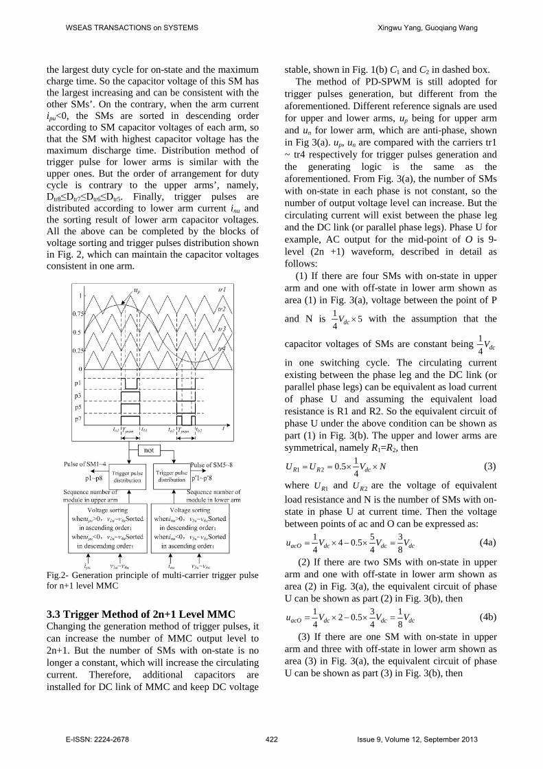
the largest duty cycle for on-state and the maximum charge time. So the capacitor voltage of this SM has the largest increasing and can be consistent with the other SMs’. On the contrary, when the arm current ipu<0, the SMs are sorted in descending order according to SM capacitor voltages of each arm, so that the SM with highest capacitor voltage has the maximum discharge time. Distribution method of trigger pulse for lower arms is similar with the upper ones. But the order of arrangement for duty cycle is contrary to the upper arms’, namely, Dtr8≤Dtr7≤Dtr6≤Dtr5. Finally, trigger pulses are distributed according to lower arm current inu and the sorting result of lower arm capacitor voltages. All the above can be completed by the blocks of voltage sorting and trigger pulses distribution shown in Fig. 2, which can maintain the capacitor voltages consistent in one arm.
Fig.2- Generation principle of multi-carrier trigger pulse for n+1 level MMC 3.3 Trigger Method of 2n+1 Level MMC Changing the generation method of trigger pulses, it can increase the number of MMC output level to 2n+1. But the number of SMs with on-state is no longer a constant, which will increase the circulating current. Therefore, additional capacitors are installed for DC link of MMC and keep DC voltage
stable, shown in Fig. 1(b) C1 and C2 in dashed box. The method of PD-SPWM is still adopted for
trigger pulses generation, but different from the aforementioned. Different reference signals are used for upper and lower arms, up being for upper arm and un for lower arm, which are anti-phase, shown in Fig 3(a). up, un are compared with the carriers tr1 ~ tr4 respectively for trigger pulses generation and the generating logic is the same as the aforementioned. From Fig. 3(a), the number of SMs with on-state in each phase is not constant, so the number of output voltage level can increase. But the circulating current will exist between the phase leg and the DC link (or parallel phase legs). Phase U for example, AC output for the mid-point of O is 9-level (2n +1) waveform, described in detail as follows:
(1) If there are four SMs with on-state in upper arm and one with off-state in lower arm shown as area (1) in Fig. 3(a), voltage between the point of P
and N is 1 54 dcV × with the assumption that the
capacitor voltages of SMs are constant being 14 dcV
in one switching cycle. The circulating current existing between the phase leg and the DC link (or parallel phase legs) can be equivalent as load current of phase U and assuming the equivalent load resistance is R1 and R2. So the equivalent circuit of phase U under the above condition can be shown as part (1) in Fig. 3(b). The upper and lower arms are symmetrical, namely R1=R2, then
1 210.54R R dcU U V N= = × × (3)
where 1RU and 2RU are the voltage of equivalent load resistance and N is the number of SMs with on-state in phase U at current time. Then the voltage between points of ac and O can be expressed as:
1 5 34 0.54 4 8acO dc dc dcu V V V= × − × = (4a)
(2) If there are two SMs with on-state in upper arm and one with off-state in lower arm shown as area (2) in Fig. 3(a), the equivalent circuit of phase U can be shown as part (2) in Fig. 3(b), then
1 3 12 0.54 4 8acO dc dc dcu V V V= × − × = (4b)
(3) If there are one SM with on-state in upper arm and three with off-state in lower arm shown as area (3) in Fig. 3(a), the equivalent circuit of phase U can be shown as part (3) in Fig. 3(b), then
WSEAS TRANSACTIONS on SYSTEMS Xingwu Yang, Guoqiang Wang
E-ISSN: 2224-2678 422 Issue 9, Volume 12, September 2013

1 10.54 4acO dc dc dcu V V V= − × = − (4c)
(4) If there are one SM with on-state in upper arm and four with off-state in lower arm shown as area (4) in Fig. 3(a), the equivalent circuit of phase U can be shown as part (4) in Fig. 3(b), then
1 5 30.54 4 8acO dc dc dcu V V V= − × = − (4d)
The generating principle of other output levels is similar with the above, not repeating.
(a) Principle of trigger pulses generation for phase U
(b) The equivalent circuit of area (1)-(4)
Fig.3- Method of multi-carrier PD-SPWM and equivalent circuit of MMC
3.4 2n+1 MMC Balancing Strategy of Capacitor voltage For the balancing control of capacitor voltage within the same arm, the method of capacitor voltage sorting can keep the voltages of SMs being nearly consistent. However, because of the number of SMs with on-state in each phase being not constant, the arm currents contain circulating components
zpi (p=U, V, W) ( zui is shown in Fig. 1(b)). The circulating currents zpi will cause large fluctuation of arm voltage and increase the RMS value of the current, thus increasing the losses. Apart from increasing the rating of the components used in the MMC, this current, if left uncontrolled, may create
unbalance and disturbance during transient [6]. So, appropriate adjusting components should be added to reference signals for weakening the impact of circulating current. Symmetrical three-phase load being assumed and only considering the affects caused by circulating current, voltage equation of DC loop for phase U is:
2
12
nzu
dc juj
diV v L
dt=
− =∑ (5)
From (5), the transfer function between circulation izu and the capacitor voltage is the first-order link, so proportional integral (PI) regulator can be used for obtaining reference value of circulation,
*zui shown in (6).
2 2*
1 11 1
( ) ( )n n
zu p u dc ju i u dc juj j
i K V v K V v dt= =
= − + −∑ ∑∫ (6)
where Kp1u and Ki1u are proportional and integral coefficients. The relationship between capacitor
voltage and current is avezu arm
dui C
dt= , where Carm is
series equivalent capacitance of phase U and uave is the average of capacitor voltages. So the control quantity for average value of capacitor voltage in phase U can be expressed as:
* *2 2( ) ( )ave p u zu zu i u zu zuu K i i K i i dt= − + −∫ (7)
The control method of the other two phases is same with phase U. From the above, the control structure for average voltage of SMs is shown as Fig. 4, where refu′ is the voltage reference signal from converter control system [12] (the follow-up DPC algorithm). Then average value control quantity uave is added into the reference value refu′ being as the final voltage reference signal uref, which is sent to the voltage sorting block for trigger pulses generation and distribution.
Fig.4- Generation principle of multi-carrier trigger pulses 4 Control strategy of VSC-HVDC for offshore wind farm based on virtual flux DPC
WSEAS TRANSACTIONS on SYSTEMS Xingwu Yang, Guoqiang Wang
E-ISSN: 2224-2678 423 Issue 9, Volume 12, September 2013

4.1 Principle of Virtual Flux The concept of "virtual flux" is result from "virtual motor". The power source of grid and wind farm side can be seen as a virtual AC "motor", grid side for example, shown as the part of dotted line in Fig. 5, where R0、L0 can be seen as stator resistance and inductance of virtual motor, C is DC capacitor, usa, usb, and usc are grid voltages, ia, ib, and ic are grid current, u′ra, u′rb, and u′rc are AC voltages of converter, ura, and urb and urc are the voltages of point A, B, and C (A′, B′, and C′), respectively [8].
Fig. 5- Principle of virtual flux base on MMC
The grid voltage is generated by the virtual flux of electromagnetic induction, so it satisfies:
sss
s s
u dt
u dt
αα
β β
Ψ Ψ = = Ψ
∫∫
(8) where sΨ is virtual flux vector to produce AC voltage of converter and its components on α - and β -axis of two-phase stationary coordinate system are sαΨ and sβΨ . su α and su β are the grid voltage of α - β coordinate. The relationship between the above vectors are shown in Fig. 6 [2], where synthesizing vector of grid voltage leads virtual flux vector 90° and both of them rotate with synchronous angular speed ω . The direction of us is consistent with d-axis of synchronous rotating reference frame. The angle between sΨ and α -axis is sγΨ . iL and ur are the synthesis vector of three-phases AC current and voltage of converter, respectively. uL is the voltage vector of reactor L0, L1. From formula of equivalent coordinate transformation, the AC voltage ura, urb, urc of converter can be transformed to α - β coordinate. Then virtual flux vector and its spatial position angle can be expressed as (9) and (10), respectively.
1( (2 ))6
1( ( ))2
s ra rb rc eq L
s rb rc eq L
u u u dt L i
u u dt L i
α α
β β
Ψ = ⋅ − − + ⋅Ψ = − + ⋅
∫
∫
(9)
2 2
2 2
sin
cos
s s
s s
rs
rs
α β
α β
β
α
γ
γ
Ψ
Ψ
Ψ=
Ψ + Ψ
Ψ = Ψ + Ψ
(10) where Leq is equivalent reactance of converter AC side, including two parts L0 and L1, and they are parallel [10], namely that the potential of points A and A′ is equal. So:
0 112eqL L L= + (11)
where ura, urb, and urc can be obtained from SMs capacitor voltages and the corresponding switching function. Phase U for example, through the above analysis of area (1) - (4) in Fig. 3, the following rules can be obtained: Assuming there are 2n SMs in upper and lower arms of phase U and each SM capacitor voltage is dcV n at steady-state, then the potential of point A(A′) decreases dcV n , when there is a SM in upper arm to be on-state. On the contrary, the potential of point A(A′) increases dcV n , when there is a SM in upper arm to be off-state. The characteristics of lower arms are opposite with the upper ones. The potential of point A(A′) increases
dcV n when there is a SM in lower arm to be on-state and on the contrary, it decreases. So the potential ura of point A in phase U of converter can be expressed as:
2
1 1
n n
ra ju ju ju juj j n
u v S v S= = +
= − ⋅ + ⋅∑ ∑ (12)
where Sju is the switching function of phase U for each SM. The calculation method of the other phases is the same as phase U.
WSEAS TRANSACTIONS on SYSTEMS Xingwu Yang, Guoqiang Wang
E-ISSN: 2224-2678 424 Issue 9, Volume 12, September 2013

Fig.6- Reference coordinates and vectors The relationship between grid voltage flux sΨ
and converter flux rΨ is as (13) according to voltage relationship us = ur + uL.
s eq L rL iΨ = + Ψ (13) From the instantaneous power theory and the
integral relationship between voltage and flux, it can be derived that there are the relationship as (14) between the power, flux, and AC current [4]-[5].
( )
( `)s s s s
s s s s
p i iq i i
α β β α
α α β β
ω
ω
= ⋅ Ψ −Ψ = ⋅ Ψ + Ψ
(14)
where p and q are input active and reactive power of the converter.
From (14), the power feedback can be calculated from the virtual flux and the rotating coordinate transformation can be oriented by flux. So the AC voltage sensor of grid side can be eliminated. From (9), flux calculation contains pure integrator and its low-pass characteristics can improve anti-interference performance of the system. However, the initial of integration for actual application is difficult to determine and system performance
degrades. In this paper, the second order 2
2( )
c
csωω⋅+
is used instead of pure integration [16], whose amplitude and phase frequency characteristics are similar to the pure integrator, and cω is system angular frequency. 4.2 Control Structure of VSC-HVDC Based on VF-DPC The structure of wind farm side or grid side converter is shown as Fig. 5. Ignoring the impact of equivalent resistance R0, in two-phase synchronous rotating d-q coordinate system to establish the mathematical model is as (15):
sdeq sd rd eq sq
sqeq sq rq eq sd
diL u u L idt
diL u u L i
dt
ω
ω
= − + = − −
(15)
where usd and usq, isd and isq, urd and urq are grid side voltage, current, and arm voltage of converter. From Fig. 6 the grid voltage synthesizing vector coincides with d-axis, so usq=0. Equation (15) multiplies with the usd at both sides and get:
2eq sd rd sd eq
eq rq sd eq
dpL u u u L qdtdqL u u L pdt
ω
ω
= − ⋅ − = ⋅ +
(16)
where the active power p and the reactive q can be obtained form (15). The (16) shows that the order of the controlled object is 1, so PI controllers can be used for controlling the active and reactive power to track the given values. For the converter of grid side, PI regulator of outer DC voltage loop should be added for controlling the DC voltage of the system, constituting the double closed-loop structure with voltage loop as the outer one and the power loop as the inner one. The dq-axis variables of inner power loop are coupled with each other, which brings difficulty for the controller designing, so the control strategy of feed-forward decoupling is used. Feedback value of power and phase information of flux can be obtained by the estimation method mentioned above. Output of power loop regulator is the reference of voltage vector. Then the control quantities ura, urb, and urc under three-phase stationary coordinate system can be obtained by inverse transformation from d-q to a-b-c coordinate according to the phase information of flux. Finally, the above method in section two and three is used to generate trigger pulses for SMs of each arm. For the converter of wind farm side, the PI controllers are used to regulate the active and reactive power transformed by the system and control strategy of feed-forward decoupling, the same before, is used for its power loop. To sum up, the control principle of the whole system can be shown as Fig. 7.
In Fig. 7 ZS is AC system impedance. , ,a b ci are
the AC currents of grid. p, q and *p , *q are the actual and given values of active and reactive power.
rdu , rqu are the reference signals of two-phase rotating coordinate being from the direct power controller, which are transformed to refu′ , refv′ , and
refw′ by dq-abc block being voltage reference signals of three-phase stationary coordinate. The final voltage control signals of converter uref, vref, wref are obtained by adding refu′ , refv′ , refw′ and uave, vave, wave which are the output of control block for capacitor voltage average value. , ,pu v wi , , ,nu v wi , and
, ,ju v wv are the upper and lower arm currents and capacitor voltages of SMs. The meaning of other variables of Fig. 7 is the same as above. The structure and corresponding variable meaning of
WSEAS TRANSACTIONS on SYSTEMS Xingwu Yang, Guoqiang Wang
E-ISSN: 2224-2678 425 Issue 9, Volume 12, September 2013

converters at both ends are symmetrical. 5 System simulation and analysis
5.1 Comparation of n+1 and 2n+1 Level MMC First, converter of wind farm side for example, simulation comparison is carried out for the two different trigger methods of MMC. Main simulation
Fig.7 Principle of VF-DPC for offshore wind farm connecting to grid based on MMC
parameters are as follows: a system power of 20MW, a DC-link voltage of ±35 kV, a line voltage RMS value of 35 kV, input resistance for converter of 4.8mH, SM capacitors of 1900 Fµ , circulation suppression reactors between upper and lower arms of 3mH, triangular waveforms frequency of 2 kHz and a stack of 4 cascaded SMs per arm. For the 2n+1 level MMC 1500 Fµ capacitors are added for DC link of the converters. The VF-DPC strategy is used and the converter of wind farm side operates with PWM rectifier state. DC power transmission cable and converter of grid side are equivalent with load resistance. At t=1s, the reference value of DC voltage step changes from 2pu (70kV) to 2.5pu (87.5kV). For the n+1 level MMC, the simulation results are shown in Fig. 8: (1) AC voltage and current of phase U in wind farm side are in phase in steady state shown in Fig. (8a), which shows that power factor is 1. (2) The 5-level PWM waveform at AC side of converter in steady state is shown in Fig. 8(b). (3) The capacitor voltages of the eight SMs in phase U is shown in Fig. 8(c) and its magnified curve during step response is shown in Fig. 8(d). From this figure, DC capacitor voltage fluctuation of n+1 level MMC is limited to less than 3kV by the method of voltage sorting. The simulation results of 2n+1 level MMC are shown in Fig. 9: (1) AC voltage and current for phase U of converter are shown in Fig. 9(a). The current curve is smoother than the one in Fig. 8(a) because of the number of output level increasing. (2) The 9-level PWM waveform at AC side of converter in steady state is shown in Fig. 9(b). Comparing with Fig.
8(b), the number of output level increases to 9 (2n +1) and the output waveforms are more regular. (3) The capacitor voltages of SMs and their magnified curve during step response in phase U is shown in Fig. 9(c) and (d), respectively. Comparing with Fig. 8(c) and (d), fluctuation of DC capacitor voltage is reduced significantly (less than 1 kV). (4) The step response of DC voltage is shown in Fig. 9(e), where Vdc1 is the output of 2n+1 level MMC and Vdc2 is the output of n+1 level MMC. Dynamic response performance of the two curves are almost the same, but voltage fluctuation of the former one (Vdc1) is smaller than the latter. Through the above comparison and analysis, the trigger method of 2n+1 level MMC designed in this paper can obtain better performance. Therefore, further simulation research on VSC-HVDC for offshore wind farm connecting to grid based on this method is carried out. 5.2 Simulation of MMC-Based VSC-HVDC for Offshore Wind Farm Simulation model of VSC-HVDC system based on MMC is set up according to the control structure shown in Fig. 7. The DC voltage is controlled by converter wind farm side and active power is controlled by converter of grid side. System capacity and voltage level are the same as above mentioned (20MVA, 35 kV). The control algorithm of VF-DPC is used for converters at both ends. Each arm consists of 4 cascaded SMs, the number of output levels are 2n+1=9. In this paper, the number of cascaded SMs is small considering the limitation
WSEAS TRANSACTIONS on SYSTEMS Xingwu Yang, Guoqiang Wang
E-ISSN: 2224-2678 426 Issue 9, Volume 12, September 2013

of simulation speed. The number of SMs in each arm can be increased according to capacity of actual system, and control principle is the same as the foregoing one. DC lines are modeled by T-type equivalent circuit in which the equivalent resistor, inductor, and capacitor of unit length are 0.0139 Ω /km, 0.159mH/km, and 0.231nF/km, respectively and the length is set 50km. For comparison, the simulation model of MMC based VSC-HVDC using double closed-loop vector control strategy is built and the parameters of PI regulators for wind farm side and grid side are showed in Tab. 1. The parameters of PI regulators for control strategy of VF-DPC is shown in Tab. 2
First of all, the situation of output power fluctuation at wind farm side is considered. The given value of reactive power is zero. DC capacitors are pre-charged to 47 kV (1.35Uf, Uf is line voltage RMS of AC system). After starting, the output power of wind farm step changes from 0.65pu to 0.95pu at t=1s for testing system performance of dynamic response. The output response curves are shown in Fig. 10: (1) the response of DC voltages is shown in Fig. 10(a), where Vdc1 is the output of DPC algorithm and Vdc2 is the output of double closed-loop vector control algorithm. The dynamic performance of Vdc1 is better than Vdc2 significantly. The DC voltage has very small fluctuation when the output power of wind farm step changes and therefore the system dynamic performance is satisfactory. (2) AC voltage and current of phase U at wind farm side and grid side are in phase and opposed phase in steady state shown in Fig. 10(b) and (c), respectively. They show that power factor is 1. The multilevel structure
Table 1- Parameters of regulators for double closed-loop vector control system
regulator proportion integral upper limit
lower limit
grid side
DC voltage
35.5 106.5 3 -3
reactive power
30.5 35 1.5 -1.5
d-axis current
0.6 6 2.5 -2.5
q-axis current
0.6 6 2.5 -2.5
wind active power
20 60 1.5 -1.5
farm
side
reactive power
3 3 1.2 -1.2
d-axis current
0.6 6 2.5 -2.5
q-axis current
0.6 6 2.5 -2.5
Table 2-Parameters of regulators VF-DPC system
regulator proportion integral upper limit
lower limit
grid side
DC voltage 8.5 105 2.5 -2.5
reactive power 3 27 1.5 -1.5
active power 0.75 27 2.5 -2.5
wind farm
side
reactive power 3 27 1.5 -1.5
active power 3 60 2.5 -2.5
is used and its equivalent switch frequency is high (8fc=16kHz, fc is frequency of triangular carrier waveform), so the current waveform is approximate smooth sine wave without passive filters. (3) Active and reactive power are shown in Fig. 10(d), where P′, Q′ are obtained by computation with the measurement value of AC voltage and current, and P, Q are the estimated value by (9)-(14). They are almost overlapped with each other respectively in steady state. It is shown that the power estimation method for MMC designed in this paper is sufficiently precise. Because the numerical difference between active and reactive power is large, per unit (p.u.) value is used in Fig. 10(d) (p.u. the system with phase voltage peak value 28.6 kV, system capacity 20 MVA). (4) The multilevel PWM waveforms of wind farm side converter are shown in Fig. 10(e). Each arm is composed of eight SMs and output voltage is 9-level. (5) Capacitor voltages of SMs in phase U are presented in Fig. 10(f) and its magnified curve during step response is shown in Fig. 10(g). The capacitor voltages within the same arm are almost equal with each other at any time (Vc1~Vc4 for upper arm and Vc5~Vc8 for lower one), which are periodical fluctuant with the frequency of 100Hz (the same as the frequency of circulating current zui ). Fluctuation of capacitor voltage during step response is small enough which shows that the performance of the strategy designed
WSEAS TRANSACTIONS on SYSTEMS Xingwu Yang, Guoqiang Wang
E-ISSN: 2224-2678 427 Issue 9, Volume 12, September 2013

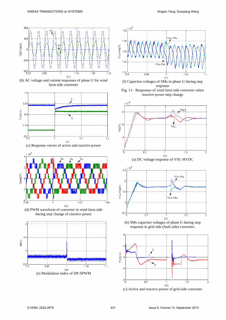
in this paper is satisfactory. Converter itself can absorb or emit some reactive
power, so reactive compensation devices are not needed, which can reduce the weight of equipment and the size of offshore platform. The reactive power step changes from 0pu to 0.6pu at t=1s and the simulation results are shown in Fig. 11: (1) The impact on DC voltage induced by step change of reactive power is small shown in Fig. 11(a). (2) Voltage and current waveforms for phase U of wind farm side stagger some phase after t=1s shown in Fig. 11(b). Some reactive power for supporting AC system can be provided by the converter. (3) Active and reactive power are shown in Fig. 11(c). (4) The voltage of converter AC side (9-level PWM waveforms of three phases) is shown in Fig. 11(d) and the modulation index M is shown in Fig. 11(e). The reactive power increases and M is decreases, so number of triangular carriers covered by the reference signal and output voltage level are decreased. However, this has little effect on quality of multi-level waveforms. (5) Capacitor voltages of the eight SMs in phase U shown in Fig. 11(f). The total output power increases induced by the step increasing of reactive, so the fluctuation of capacitor voltages increases slightly during reactive power step changing, but doesn’t affect system operation. Transient process is common in power system, for example three-phase short circuit, short circuit to ground and so on. It is essential for VSC-HVDC system to have the ability of anti-interference, especially used for offshore wind farm. The fault of three-phase short circuit to ground starts at t=1s and continues for 0.12s at grid side. The response curves are shown in Fig. 12: (1) DC voltage can track the given value at about 0.6s after recovery shown in Fig. 12(a), where Vdc1 is the response of DPC controller and Vdc2 is of double closed-loop vector control strategy. The overshoot of Vdc1 is less than Vdc2. It is proved that dynamic performance of DPC is better than vector control, again. (2) Capacitor voltages of phase U at grid side are shown in Fig. 12(b). The voltages increase less than 30% and numerical difference of SM voltage between upper and lower arms is about 5kV (7.1%Vdc) during the transient. (3) Active and reactive power of grid-side converter (fault side) is shown in Fig. 12(c) and track the given value at about 0.7s after recovery. There are overshoot and oscillations occurrence during the transient and dual vector or other control strategies can be used for suppressing the overshoot [17]-[18], but it exceeds the field of this paper.
6 Conclusion Based on MMC topology, simulation research of VSC-HVDC for offshore wind farm is carried out. Technology of multi-carrier PD-SPWM is used for generating trigger pulses of converter SMs. For different modulation method of MMC (n+1 and 2n+1 level MMC), different control strategies (capacitance-voltage sorting and adding balance component to reference signal) for voltage balancing are adopted, respectively. At the same time the additional DC capacitors are used for DC link to improve the performance of DC voltage and reduce its fluctuations. Simulation results show that 2n+1 level MMC with additional DC capacitors possessing more excellent dynamic and static performances.
To improve the system dynamic performance, the strategy of VF-DPC is used for MMC-based VSC-HVDC. Active and reactive power can be controlled independently and current waveform is smooth, closing to sine wave, without passive filters. The phase-locked loop (PLL) is replaced by virtual flux-oriented to achieve synchronization with grid voltage, eliminating the AC voltage sensor of grid and with the advantages of cost savings, improving the performance of anti-interference. Power and virtual flux estimation algorithms for the MMC are designed and by comparing with actual power shows the precision of power estimation algorithm is high. Finally, the performances of system response under various conditions are simulated and compared with traditional strategy of double closed-loop vector control. The results show that the MMC-based VSC-HVDC system designed in this paper possesses more excellent performance
(a) AC system voltage, current response of phase U for grid side
WSEAS TRANSACTIONS on SYSTEMS Xingwu Yang, Guoqiang Wang
E-ISSN: 2224-2678 428 Issue 9, Volume 12, September 2013

(b) 5-level PWM waveform of converter in phase U
(c) Capacitor voltages of SMs in phase U
(d) Magnified curve of capacitor voltages during step
response Fig. 8- DC voltage step responses of n+1 level MMC
(a) AC system voltage, current response of phase U for
grid side
(b) 9-level PWM waveform of converter in phase U
(c) Capacitor voltages of SMs in phase U
(d) Magnified curve of capacitor voltages during step
response
(e) DC voltage of n+1 and 2n+1 MMC.
Fig. 9- DC voltage step responses of 2n+1 level MMC
WSEAS TRANSACTIONS on SYSTEMS Xingwu Yang, Guoqiang Wang
E-ISSN: 2224-2678 429 Issue 9, Volume 12, September 2013

(a) DC voltage response of n+1 and 2n+1 MMC-based
VSC-HVDC
(b) AC voltage and current responses of phase U for wind
farm side converter
(c) AC voltage and current responses of phase U for grid
side converter
(d) Active and reactive power obtained by estimation and
measurement
(e) PWM waveform of converter in wind farm side
(f) Capacitor voltages of SMs in phase U
(g) Magnified curve of capacitor voltages during step
response Fig. 10- Responses of MMC-based VSC-HVDC when
active power step change from wind farm
(a) DC voltage response
WSEAS TRANSACTIONS on SYSTEMS Xingwu Yang, Guoqiang Wang
E-ISSN: 2224-2678 430 Issue 9, Volume 12, September 2013
(b) AC voltage and current responses of phase U for wind
farm side converter
(c) Response curves of active and reactive power
(d) PWM waveform of converter in wind farm side
during step change of reactive power
(e) Modulation index of DP-SPWM
(f) Capacitor voltages of SMs in phase U during step
response Fig. 11- Responses of wind farm side converter when
reactive power step change
(a) DC voltage response of VSC-HVDC
(b) SMs capacitor voltages of phase U during step
response in grid side (fault side) converter.
(c) Active and reactive power of grid-side converter
WSEAS TRANSACTIONS on SYSTEMS Xingwu Yang, Guoqiang Wang
E-ISSN: 2224-2678 431 Issue 9, Volume 12, September 2013

Fig. 12- Responses of MMC-based VSC-HVDC during transient grid fault. Acknowledgements
This work was supported by Natural Science Foundation of China(No.51207086), Innovation Program of Shanghai Municipal Education Commission(No.14YZ126), Shanghai University Scientific Selection and Cultivation for Outstanding Young Teachers in Special Fund(No.sdl12004) References: [1] Shuang Li, Zhixin Wang, Guoqiang Wang, “A
feedback linearization based control strategy for VSC-HVDC transmission converters,” WSEAS Transactions on Systems, vol. 10, no. 2, pp. 49-58, Feb 2011.
[2] T. Noguchi, H. Tomiki, S. Kondo, and I. Takahashi, “Direct power control of PWM converter without power-source voltage sensors,” IEEE Trans. Ind. Appl., vol. 34, no. 3, pp. 473-479, May 1998.
[3] Yang Xingwu, Jiang Jianguo, “Predictive direct power control for three-phase voltage source PWM rectifiers,” Proceedings of the Chinese Society of Electrical Engineering, vol. 31, no.3, pp. 34-39, Jan 2011.
[4] Azizi Hossein, Vahedi A., Papi G.H. “Investigation of power quality disturbance effects on the direct power controlled PWM rectifier” WSEAS Transactions on Systems., vol. 4, no.10, pp. 1777-1784, Oct. 2005.
[5] Yang Xingwu, Zhao Jianfei, Yang Xinghua, Jiang Jianguo , “Direct power control based on output voltage computation technique for AC/DC converters,” Proceedings of the Chinese Society of Electrical Engineering., vol. 30, no. 36, pp. 59-64, Dec 2010.
[6] Rafiei Mohammadreza , Ghazi Reza, Asgharian Radjab, Toliyat Hamid A., Barakati Masoud, “Robust control methodologies for dc/dc PWM converters under wide changes in operating conditions,” WSEAS Transactions on Systems., vol. 5, no. 11, pp. 2655-2665, Nov, 2006.
[7] Bouafia, A., Gaubert, J.-P., and Krim, F., “Predictive Direct Power Control of Three-Phase Pulsewidth Modulation (PWM) Rectifier Using Space-Vector Modulation (SVM),” IEEE Trans. Power Electron., vol. 25, no. 1, Jan. 2010.
[8] Antoniewicz, P., Kazmierkowski, M.P., “Virtual-Flux-Based Predictive Direct Power Control of AC/DC Converters With Online Inductance Estimation,” IEEE Trans. Ind.
Electron., vol. 55, no.12, pp. 4381-4390, Dec. 2008.
[9] Bouafia, A., Krim, F., and Gaubert, J.-P. “Fuzzy-Logic-Based Switching State Selection for Direct Power Control of Three-Phase PWM Rectifier,” IEEE Trans. Ind. Electron., vol. 56, no. 6, pp. 1984-1992, June 2009.
[10] Tu Qing-rui, Xu Zheng, and Zheng Xiang, et al. “Mechanism Analysis on the Circulating Current in Modular Multilevel Converter Based HVDC,” High Voltage Engineering, vol. 36, no. 2, pp. 547-552, Feb. 2010.
[11] Rohner, S., Bernet, S., and Hiller, M. et al. ”Pulse width modulation scheme for the Modular Multilevel Converter,” European Conference on Power Electronics and Applications, Dresden, Germany 2009, pp. 1-10.
[12] Makoto Hagiwara, Hirofumi Akagi, “Control and Experiment of Pulsewidth-Modulated Modular Multilevel Converters,” IEEE Trans. Power Electron., vol. 24, no. 7, pp. 1737-1746, July 2009.
[13] Antonopoulos, A., Angquist, L., and Nee, H.-P., “On dynamics and voltage control of the modular multilevel converter,” Power Electronics and Applications Conference, Barcelona. 2009, pp. 1-10.
[14] Gao Chun, Jiang Jianguo, Yang Xingwu, Xie Liang, Cao Kai, “A novel topology and control strategy of modular multilevel converter (MMC)” 2011 International Conference on Electrical and Control Engineering, 2011, pp. 967 – 971.
[15] Liu Zhongqi, Song Qiang, and Liu Wenhua, “VSC-HVDC System Based on Modular Multilevel Converters,” Automation of Electric Power Systems, vol. 34, no. 2, pp. 53-58, Jan. 2010.
[16] Chen Wei, “Research and Realization on Direct Power Control of Three-phase Voltage-source PWM Rectifier”, Ph.D. dissertation, Dept. Elect. Eng. Huazhong Univ. of Science and Technology, Hu Bei, China, 2009.
[17] Neri Filippo, “Empirical investigation of word-of-mouth phenomena in markets: a software agent approach” WSEAS Transactions on Computers., vol. 4, no. 8, pp. 987-994, Aug. 2005.
[18] Lie Xu, Andersen, B.R. and Cartwright, P., “VSC Transmission Operating Under Unbalanced AC Conditions-Analysis and Control Design,” IEEE Trans. Power Del., vol. 20, no. 1, pp. 427-434, Jan. 2005.
WSEAS TRANSACTIONS on SYSTEMS Xingwu Yang, Guoqiang Wang
E-ISSN: 2224-2678 432 Issue 9, Volume 12, September 2013