research report 051 - hse: information about health … · · 2017-07-15research report 051. hse...
TRANSCRIPT
HSE Health & Safety
Executive
PTO shaftguardsDevelopment of strength tests for
tractor/machine ‘interface’ standards
Prepared by Seward Engineering Limited and Silsoe Research Institute
for the Health and Safety Executive 2002
RESEARCH REPORT 051

HSE Health & Safety
Executive
PTO shaftguardsDevelopment of strength tests for
tractor/machine ‘interface’ standards
P C Seward Seward Engineering Limited
85 Cambridge Road Langford
Bedfordshire SG18 9PL
D A Semple Silsoe Research Institute
Wrest Park Silsoe Bedfordshire MK45 4HS
The Health and Safety Executive (HSE) commissioned this research following the meetings of June 2001 in Frankfurt of ISO/TC 23/SC2. Working Group 5 of which subsequently produced ISO DIS 5674 ‘Tractors and machinery for agriculture and forestry-Guards for power take-off (PTO) drive shafts -Wear and Strength Tests’, incorporating the latest proposed changes to the Standard. These proposals included test methods and pass fail-criteria, which were derived from various sources, including practical tests, manufacturers’ own research and previous projects sponsored by the HSE.
This latest project was undertaken primarily to investigate developments within CEN on the same subject under the terms of the Vienna Agreement. The particular draft standard (PrEN 12965) is intended to define the safety issues surrounding PTO Shaft Guards and the tests it calls up are contained in EN 1152 which is the equivalent of ISO 5674. The CEN working group will pass all activities on this subject over to the ISO working group after it has produced EN12965.
It was also considered necessary to examine how the Standard could be applied to new designs of guard, which are needed to fit shafts with an ever-increasing number of special attachments. The designers are currently limited in the way they can adapt to technical change by the way the Standard is written. It was intended to provoke discussion, attract input from experts and provide technical data, which would contribute to the process of revising the Standard.
This report and the work it describes were funded by the Health and Safety Executive (HSE). Its contents, including any opinions and/or conclusions expressed, are those of the authors alone and do not necessarily reflect HSE policy.
HSE BOOKS

© Crown copyright 2002
First published 2002
ISBN 0 7176 2588 5
All rights reserved. No part of this publication may bereproduced, stored in a retrieval system, or transmitted inany form or by any means (electronic, mechanical,photocopying, recording or otherwise) without the priorwritten permission of the copyright owner.
Applications for reproduction should be made in writing to: Licensing Division, Her Majesty's Stationery Office, St Clements House, 2-16 Colegate, Norwich NR3 1BQ or by e-mail to [email protected]
ii

CONTENTS
SUMMARY v
1. INTRODUCTION 1
1.1 RATIONALE AND BACKGROUND 1 1.2 OBJECTIVES 2 1.3 ACTIVITIES AND MONITORING 2 1.4. DELIVERABLES 3
2. STUDY OF RELEVANT PAPERS AND RECENT DEVELOPMENTS 4
2.1 REVIEW OF THE MOST UP TO DATE DRAFT FOR THE NEW ISO 5674 4
2.2 THE TEXT OF THE DRAFT STANDARD 6
3. NEW TEST METHODS INCLUDING THE ADAPTATION OF TEST RIGS TO FOLLOW CEN RECCOMENDATIONS 16
3.1 DYNAMIC SWIVEL TEST 163.2 CHANGE OF POSITION OF RADIAL LOADING 19 3.3 IMPROVEMENTS TO THE DYNAMIC AXIAL
LOADING TEST 21 3.4 TESTS FOR ROTATING GUARDS 26 3.5 INCREASE IN TESTING TIME, EFFORT AND COST 29
APPENDICES
APPENDIX 1
APPENDIX 2
APPENDIX 3
APPENDIX 4
INTRODUCTION OF A TEST FOR DAMAGE AND CONTACT WITH THE STANDARD TRACTOR MASTER SHIELD 31
COMMENTS FROM DELEGATIONS ON THE DRAFT STANDARD 35
FINAL ADJUSTMENTS TO DYNAMIC AXIAL TEST 49
REVIEW OF PROPOSALS TO MOVE RADIAL LOADING ON CONES (SECTION 6.3.1.2.) 51
iii

iv

SUMMARY
The project was commissioned by HSE who are concerned about the safety of power take-off shafts for agricultural tractors and their guards, as defined by the Standard ISO 5674 (EN 1152 is the CEN equivalent). Deficiencies in the performance of tractor Power take-off shaftguards identified through observations in the field and commissioned research over a number of years, could be remedied by further contributions to the development of better test standards, which will, in turn, influence the design of guards.
A great deal of work has been carried out by the HSE and other members of Working Group 5 of ISO TC23 SC2 to develop Draft International Standard (DIS) 5674 which has been circulated for voting. The document, ISO TC 23/SC 2 N 413 has received a positive vote but several queries have been made by international delegations to ISO, about new tests contained within it. This research aims to answer those queries and promote involvement by manufacturers and other experts in advocating its’ adoption as a CEN standard under the Vienna Agreement.
· The DIS has been compared with other ISO standards with which it links, as well as with both new and existing EU standards covering the same general topic
· Perceived problems with test equipment and methods have been analysed and solutions offered
· Meetings have been attended and contacts established to promote the progress of the document
· Test equipment has been designed and modified or constructed from scratch to develop test methods
· The use and miss-use of PTO guards and equipment has been observed in the field and taking special note of novel guarding systems, the information has been used in developing the draft standard
· A Working Group meeting will be held jointly with the CEN representatives to promote the acceptance of the standard, during which, the contents of this report will be used to support the case
v

vi

1. INTRODUCTION
1.1 RATIONALE AND BACKGROUND
HSE has been actively involved in developing CEN and ISO standards for the testing of PTO shaft guards. The standard, ISO 5674 has been reviewed at recent ISO meetings and HSE has taken a lead through its involvement as convenor of a working group on this subject and by commissioning research work. The work has been accepted and forms the backbone of the revised standard, which has reached the ‘DIS’ stage within ISO. The working group has been asked to take into account developments within CEN on the same subject under the terms of the Vienna Agreement and the CEN working group will pass all activities on this subject over to the ISO working group after it has produced EN12965. This particular standard (12965) is intended to define the safety issues surrounding PTO Shaft Guards but the tests it calls up are contained in EN 1152 which is the equivalent of ISO 5674. During the development of 12965, a safety issue concerning the interference between shaft guards and the ‘master shields’ on the tractor and machine was raised. A test was devised, in outline, to address the problem, by the CEN working group, who proposed to insert it into 12965. The standard concerned was not considered to be the correct vehicle for this type of test by ISO and it has been decided to investigate the possibility of putting the test into ISO 5674 before the next DIS vote. On the understanding that all the ISO and CEN standards on Shaftguards can be commonised from the next revision of EN1152, acceptance of the principles within ISO 5674 and 5673 (which is also currently under review), will result in a true harmonisation within the next two years.
Before ISO can accept the proposed test, it is necessary to fully check the principles, which appear to be based on reasonable theories but have not been thoroughly researched or tried out by test bodies or manufacturers. . The resultant standard must be:
a. Appropriate for the current designs, and
b. adaptable to test novel guards which are coming onto the market
This work is therefore designed to bring together all the latest knowledge on shaftguard safety within the short timeframe available. Working with manufacturers and test bodies, it would adapt the proposed test, along with any outstanding technical issues from the ISO working group so that they can be incorporated in the current review of ISO 5674 before the final DIS voting next February
The main author and the person in charge of this and previous work was P. Seward who used the facilities of Silsoe Research Institute (SRI). SRI has been involved in many of the research projects connected with this subject. D. Semple is the SRI member of staff now responsible for shaft guard testing and he was involved from the beginning and participated in all aspects of this project.
1

1.2 OBJECTIVES
Taking into account recent research work on PTO shaft guards which has been done by guard manufacturers as a result of the ongoing review of ISO’s 56574, 5673 and EN’s 12965 and 1152, establish work programmes and where appropriate, involve the manufacturers who have already pledged equipment and resources. To research the fundamental theories upon which the proposed tests are based, especially those tests which involve the inter-action between the guarding of the PTO shaft at both the tractor, and the machine connecting points.
Aims Of The Work:
1.2.1 Information about the effects of contact between the guarding of the PTO shaft and the guards on the tractor and recipient machine will be extracted from existing data, verified with manufacturers, dealers, farmers and, where necessary, by inspection and measurement of machines in the field. Addendum (The aims were widened to include involvement in the development meetings for ISO 500 and 5673, ISO TC23/SC4 WG/8 where extensive discussions also took place on the developing PrEN 12965.)
1.2.2 Information will be obtained by experimentation using existing test rigs modified to the requirements of the proposed new tests from prEN12965 and the findings used to suggest appropriate modifications to the tests.
1.2.3 The provisions of the new DIS5674 will be revised in line with developments in the above mentioned European standards and other ISO standards such as ISO 5673. Particular attention will be paid to the need to accommodate new designs of shaftguard.
1.2.4 Any other issues resulting from the working group discussions on the DIS will be investigated and resolved where practicable within the constraints of this programme.
1.3 ACTIVITIES AND MONITORING
Comments in Italics are the scope and limitations:
1.3.1 Study and bring together all relevant data and papers. Using the latest research from U.K. and taking into account the most recent work of the manufacturers of shaft guards and other interested parties.
1.3.2 Adapt test rigs and carry out appropriate tests and trials to evaluate the principles of the strength tests which are being proposed in CEN. Investigate how they could be adapted to fit in with the latest version of ISO 5674 and taking into account the wear, damage and hazard problems identified by recent research, make proposals which are both suitable for the new ISO and as counter-suggestions for prEN 12965.
Particular attention will be given to the subject of ‘adaptation to technical progress’ and current novel designs of guard (both on the shaft and on the tractor and machine) which seem to have been overlooked in the CEN proposals.
2
1.3.3 Inspect working equipment where necessary, and analyse all available information from users, safety inspectors and manufacturers about the more extreme use of PTO shafts. Particular attention will be paid to re-creating the angles involved in their storage and use, which will then be taken into account during alterations to test equipment and revisions of the Standards.
Opportunities will be taken to involve the guard manufacturers and users in the process and measurements and pictures will be used to illustrate particular problems where appropriate.
. 1.4 DELIVERABLES
From the various activities listed above there will be the following deliverables:
1.4.1 A programme of testing will be enacted, as drawn up in consultation with HSE, which defines modifications to the proposed tests. Manufacturers, Users and members of the appropriate ISO working group of TC 23 and the CEN working group will be consulted where appropriate.
1.4.2. An interim reports to H.S.E., which provides information for discussion at a September meeting of the ISO TC23/SC3 working group.
Addendum The meeting date was changed so the research was put on hold until June 2002
1.4.3. A final report will be produced which defines new tests, evaluates the effectiveness of the current tests and discusses how the proposed revised Standard aligns with other ISO and CEN standards under review.
3
2. STUDY OF RELEVANT PAPERS AND RECENT DEVELOPMENTS
2.1 REVIEW OF THE MOST UP TO DATE DRAFT FOR THE NEW ISO 5674
Only one month before the planned July 2002 meeting of ISO TC/23/SC2/WG5, the convenor was informed that the CEN Machinery Directive Consultant was required to give a report before a final meeting to discuss the future of any draft standard being put forward for joint numbering. As the consultant had not been informed of the progress of the project, it was thought necessary to provide some insight into the reasons for the new edition of ISO 5674, and trust that he would take account of the notes when making his report.
The summary report is reproduced below. Notes are appended (marked ‘Addendum) to each point with references to items of work that have been produced to support the various points that have been made since the original version went to CEN. References are also made to comments received from national delegations and tabulated in Appendix 2. Where short notes are sufficient, they follow each original point. Various larger items of work referred to and carried out during this research programme in response to comments and queries are contained in later sections or the appendices to this report.
The text below had been submitted to the CEN consultant as: “HSE SUMMARY OF DIFFERENCES BETWEEN THE EXISTING EN 1152:1994 AND THE
NEWEST DRAFT VERSION OF 5674, ISO TC23 SC2 N438, AS SUBMITTED FOR “DIS” (Draft International Standard) VOTING BY 22/4/02”
Background to the evolution of EN 1152 and ISO 5674. EN 1152 was introduced to provide a means of complying with the requirements for PTO shafts and their guards under Annex IV of the Machinery Directive. The existing ISO 5674 was adapted and published as EN 1152 without the Standard 5674 having been withdrawn. Mr Makin, the CEN consultant of the day, accepted the original EN 1152 with a proviso that it be systematically reviewed at the earliest opportunity because there was some uncertainty about its technical merit and a lack of research to confirm its likely effectiveness.
International concern about accidents involving Pto shafts The number of accidents concerning PTO shafts, although diminishing gradually, has still remained high and the resulting injuries often serious or fatal. Concern within UK and other countries over the poor condition of guards found working in the field prompted the call for a review of standards as a means improving the design and use of shafts and their guards (see New Work Item proposal from BSI to ISO as presented in Appendix 2 of HSE contract report 253/1999). Consequently, the opportunity to begin the work came up first under the review process of ISO.
With EN 1152 in place, ISO 5674 could have been dropped and the EN dual numbered however, as the review of 1152 was some way off it was thought better to revise 5674 with the hope of dual numbering at the review phase of 1152 (see CEN TC 144 N647 WI 129, corresponding to resolution 203 :1999). The UK, France and Finland have all recently published results of research into the effectiveness of PTO shaft-guards in the field today.
4
Strategy for developing test standards for Pto shaft-guards on a truly international basis.
The production and sale of PTO shafts and their guards is a worldwide business with products being bought and sold between EU and other nations who cannot always work directly to EU standards. It was decided that the standard for testing PTO guards should be usable worldwide and consequently CEN approved the development under the leadership of ISO. It was deemed essential to research the problems and develop the standard with the full participation of representatives of manufacturers, users and legislators on a global basis and to promote more effective ‘ownership’ of the concepts covered within the standard.
It was accepted at the outset that the current standard was restrictive to innovative design and did not facilitate adaptation to technical progress. These two factors could be a barrier to the improvement of designs and particularly the improvement of safety provided by PTO shaft-guards as they are required to be used in an increasing range of configurations. Not only is the range of shapes and sizes of shafts growing but the ways they are used (and particularly misused) and stored are changing along with farmers working practices. They have to adapt to less labour being available to maintain equipment correctly amongst other things.
Document title and format
The DIS document was given the following title and the latest format from ISO for its’ presentationwas adopted. Comparisons are made with the existing EN 1152 and references made to other standards where appropriate.
Title: ISO TC23 SC2 N438
No difference (except [accidental?] transposition of the words ‘wear and strength’)
Contents: The DIS has been written to separate out the Normative references, general test conditions, and equipment requirements and to introduce some new tests.
Foreword: New foreword follows ISO guidelines
Introduction:
(Actual text from the draft standard) ‘ This International Standard may be used to test all designs of PTO drive shaft guards. Some tests may require adaptation to cope with non conventional designs and an example of a test schedule for a non conventional design i.e. Bellows type is included at Annex B.’
‘Attention of the user of this standard is drawn to the fact that rotating guards are not authorised inall countries. This standard was established without prejudice to applicable national regulations. It isleft to the responsibility of the user of this standard to check the rules for the country concerned with the competent authority.’
EN 1152 was limited to a particular design but the new ISO 5674 introduces the possibility of testingmore innovative designs and thereby adapting to technical progress and encouraging better designsof guard.
1152 did not cover rotating guards nor did it mention that it could be used for testing guards that inwhole or part were different from the conventional design. The second paragraph is an attempt to provide a solution to the en-passé involving the US guards. Many are built to rotate freely, more than 60% of their market, with no evidence of a worse safetyrecord and the EU who effectively ban rotating guards via a section written in the Machinery Directive.
5

Addendum Further progress has been made on many of the above points and detailed explanations of the work can be found in the following text.
2.2 THE TEXT OF THE DRAFT STANDARD
2.2.1 Scope
(1 Scope:)
(Actual text from the DIS) ‘’This International Standard specifies laboratory tests for determining the strength and wear ‘resistance as well as requirement of guards for PTO drive-shafts as defined in ISO 5673. This International Standard is applicable to test PTO drive shaft guards with non-rotating and also with rotating guards. Regulations for guard type, e.g. non-rotating or rotating guard are outside of the scope of this standard and they may vary regionally. Some sectors of this standard may also be used to test non-conventional guard designs provided there is no reduction in the severity of the test. In such cases it shall be made clear that the product be certified to meet only relevant parts of this standard.
5674 explains the new wider scope and dispenses with the ‘get out clause’ in 1152 about Ultra Violet radiation because this factor is now specifically dealt with in the standard.
Addendum Background research that contributed to this section of the standard can be found in UK HSE Contract Research Report 323/2001 and the author has made contributions to the ongoing debate on the subject. Comments from delegations contained in the DIS voting returns, Appendix 2, show how there is general acceptance of the importance of Quality control in the selection of materials for the construction of shaft-guards. No additional research was carried out this time.
The comments about the standard being used for other types of guard that cannot be tested under all the sections of the standard also reflects the fact that the procedures provided are employed by a test body under wider rules of certification than just EN 1152 or ISO 5674. For example,the strength and wear tests would normally be carried out in conjunction with another standard such as EN 12965 (not yet published) or ISO 5673 and further risk assessments following essential safety requirements could also come into play in such cases.
Addendum UK research has continued to show that attempts to encapsulate everything relating to all the essential safety requirements concerning a particular item, such as a shaft and guard in this case, proves difficult. Attempting to do so in the case of EN 1152 has produced stereotypical designs that are hard to avoid. Every time someone tries to develop a new guard or part of a guard to react to a design challenge or improve safety and durability, they are thwarted by the conditions laid down in the only recognised test standard for that item. The mention of ‘rotating guards’ recognises a very important difference in design and highlights the fact that there must be room in a truly international standard to set down tests for certain designs that may not be acceptable in every country.
6

In ISO, it is not necessary to provide a complete solution in one standard. It is never the less desirable to have one or two standards that are complementary and can be cross referenced to enable testing bodies and designers to decide whether a particular object is fit for purpose and safe enough to use in the environment for which it is intended. The inclusion of references to ‘non-conventional guards’ in the scope reflects the attitude of ISO members both in and outside the EU and is a challenge to the EU to broaden its outlook on such matters for the sake of progress. Further references are made to these matters later in the text and various solutions discussed.
2.2.2 Normative
(2 Normative references)
Section not in 1152. 5674 has this section to comply with ISO regulations. It serves to define exactly what other standards (and their revisions) it links with. ISO 5673 is particularly relevant, as would be EN 12965 when it comes out.
Addendum Normative references are essential to enable correct interpretation of standards. They also help in the development processes by ensuring that development committees take account of the influence any changes they wish to make to a particular standard might have on others that are linked to it. This process needs to be improved because some standards refer to others that in turn do not reference them! Completion of the references for this standard at this stage are difficult because if it becomes an EN as well as an ISO there will have to be references to parallel standards in both arenas that are not yet dual numbered such as ISO 5673 and EN 12965. Possible conflicts and anomalies arising from this will emerge later.
2.2.3 Terms
(3 Terms and definitions)
Called ‘2 Definitions’ in 1152 The new text is specific about the link with 5673 and gives a definition of rotating guards.
Addendum The comment in the scope above, apply here also but in addition, there is an important reference to ISO 5673, which is currently under review. Part of the remit of this research was to take an active part in the development of ISO 5673 to encourage cross-referencing of developments, which were taking place under different ISO committees. The same brief existed for comparing developments in CEN with PrEN 12965 but the involvement was in detailed reviewing of papers and meeting reports only, although, contacts with delegates to the meetings were maintained throughout.
2.2.4 General
(4 General Test conditions) In the testing process, 5674 separates out issues like ambient conditions, tolerances, sequencing, sampling, marking and adherence to manufacturers’ instructions.
7

Rationale: The concept of Quality Control in testing and manufacture is critical in the way the MachineryDirective is designed to work.EN 1152 section ‘Test conditions’ avoided being too prescriptive and in so doing, did not put a suitableemphasis on some very important points that relate to ‘Quality Control’.
It is also intended that the standard will demand better Quality Control of manufacturing materials and processes. Research from UK, France and Finland has all pointed to the lack of attention paid toquality control by manufacturers being a factor in the poor performance of some shaft-guards in the field.
Addendum As mentioned above, there exists a generally poor grasp of modern Quality control systems as applied to the manufacture and testing of PTO shaft-guards. The fact that within the EU shaft-guards are highlighted by the Machinery Directive (98/37/EC) as safety components in its’ Annex IV, they must be tested and the tests must be approved by a ‘Notified Body’. Notified Bodies are controlled by their ‘Quality Systems’ and the Machinery Directive could not operate without such systems. Quality systems are the cement that holds everything together in that, test techniques and apparatus are properly documented and test reports are approved on the trust that the quality of production and checks of conformity will be maintained by the manufacturer. In turn the Notified Body will be accredited through internationally recognised Quality schemes such as EN/ISO 1725). When making standards, it is essential that attention is paid to the needs of the testing and certification bodies as well as the designers and manufacturers. This new standard attempts to address those needs by being more specific about tolerances and limits and to offer test techniques that stand a chance of being operated and calibrated within the confines of modern quality systems. All sections below have a connection with this issue and references are made where appropriate.
2.2.5 Test Equipment
(5 Test equipment) Following the previous section, the specific values and measurement constraints are listed according to each part of the test.
Rationale: This is intended to help with the accreditation processes for test installations and is again considered to be in-line with modern testing under EN/ISO 17025 Quality Systems.
Addendum Following on from what was said above, it is also important not to tie the hands of the tester too much, especially when he can see away to improve testing apparatus or when he has to adapt his normal methods to respond to an innovative design of guard. At the same time, the suggested methods should not demand such sophisticated mechanisms that only the most affluent countries can afford to offer the testing service.
2.2.6 Tests
(6 Tests) (6.2 Wear tests)
(6.2.4.4 Bearing corrosion test) Note: Comments about the purpose of this test were followed up by some research that proved the oldtest was not having the intended effect. HSE Contract Research report 323/2001The 5674 version moves the test sequences to an annex and separates out the old test in a salty atmosphere.
8

Rationale: This is done to re-define its purpose as a test for the effects of corrosion on metal components. It isalso made optional for designs of guards that do not have contact with metallic parts. The aims is: · to test guards of novel design· reduce unnecessary testing· make the method more controllable and actually achieve its intended effect
Addendum Comments from some delegations still indicate a lack of understanding about this topic. This is perhaps due to their not attending many meetings and not reading the HSE contract reports. This research exercise did not involve any more practical work on this subject but delegates were informed directly of the importance of having tests that actually addressed the issues for which they were intended and were not impossible to Quality Control. One delegation raised the objection that the salt test would no longer apply to the restraining members but the researcher argued that the timescale for rusting would not allow sufficient degradation of the chains to possibly cause weakening. The comments have overall not been technically damning and the Secretariat has agreed to discuss the subject further for clarification and possible editorial adjustments if required at the next meeting.
(6.3 Strength tests) Several changes have been made to the tests of 1152, new tests added and they have been re-organised to be interspersed with the wear tests.
Rationale: It was thought necessary to be more specific about the aims of each test so that test engineers and manufacturers could more easily interpret the procedures. This was especially important when adapting the standard to test less conventional designs of guard. The tests in section 5 of EN 1152 were thoroughly researched as it was difficult to know the reasons behind the way the tests were done and the how the loading levels were selected. It was concluded that the strength tests needed upgrading and some new ones added.(Further explanation appears next to the actual test below) . One improvement was that The tests would be interspersed with the wear tests to give a better check that the guard was able to function after being subjected to actions that were intended to simulate misuse in the field. (The concept of miss-use being highlighted by the Machinery Directive as a factor to consider)
Addendum Research has taken place on several elements of the ‘strength tests’ and other delegations and manufacturers have been consulted about their ideas of how to do the tests and how practicable they might be. The test rigs of Silsoe Research Institute have been adapted to find out if there are any serious problems and to try to resolve any if possible. Some adaptations had been made to produce the other HSE contract research reports that had formed the basis of many of the proposed changes to ISO 5674. Some had not been developed to a workable day to day test rig, some had not been modified to improve the flow of the new test sequences and others had not been built at all. The following sections explain what was done and the progress to date.
9

(6.3.1 Dynamic radial loading tests at ambient temperature) The test sequence has been divided up to emphasise the purpose of each part.
Addendum Appendix 4 Part 1, relates the response to a development of the standard that had not previously been advocated but found its way into a suggestion for new diagrams and was supported by several delegations. The paper was produced to promote further discussion and some research was done which is in Chapter 3, that helped to develop the arguments and seeks to document the thought processes involved in case there is a need to revise the proposal at a later date. It is important to reiterate the difficulties encountered when trying to improve this standard and to point out that lack of documentation and explanation of the principles behind the tests has hindered the process enormously.
A new rig has been designed to enable the application of radial loads whilst the shaft is still in one of the wear test rigs. The extra radial loading would cause an appreciable increase in the time and effort of testing otherwise and some estimates of this have been made. There are consequences to be considered regarding quality control and rig accreditation at this point.
(6.3.4 Dynamic swivel test) This test was added to reflect developments in PrEN 12965:2000
Rationale: ISO consider that structural tests should be in 5674 and not in 5673 which will be the virtualequivalent of 12965.
Addendum This test is in ISO 5674 but no test rigs seem to exist that could be used for automated testing. Hand operated rigs at the Finnish test station and at GKN Walterscheid can be operated manually but this would not be efficient for routine testing. Research has been carried out to look at the details of the test, where it will be used and the limits to which the equipment will need to operate. Angles of tested guards are discussed and an automated working rig has been developed.
(6.3.5 Static axial loading test at ambient temperature) This section remains the same except that ‘each end shall be tested’ whereas 1152 only requires ends of a different design to be tested.
Rationale: The design of end connections often looks the same but testing and research has shown that there can be a hidden difference and it does not add much to the length of the tests to test both ends as a matter of course.
Addendum The researcher is interested in the extra time these operations will take and this is discussed in chapter 3.
(6.3.6 Dynamic axial loading tests of the bearings at ambient temperature) 1152 contains no dynamic end-loading test for the bearings.
Rationale: Research had shown that despite guards passing the 1152 test, there were still examples of damage in the field that seemed to indicate a weakness in some bearings. Conclusions were made that the breakage’s could be due to design deficiencies that allowed the bearing to ‘corkscrew’ or jump out of its locating groove and thereby cause either catastrophic damage or damage that would accumulate to significantly reduce the effective life of the guard.
10

Addendum Further development of the test rigs has taken place and an inadvertent insertion of the requirement to test ‘in both directions’ has been investigated. Calibration issues have been highlighted and an adaptation to the rig provided to help with that problem. Pictures are provided and a section in Chapter 3 outlines the processes to be overcome in accrediting such a piece of test apparatus. The standard must be written in such a way that the required accuracy’s are possible on the rig.
(6.4.1 IMPACT TEST AT SUB-ZERO TEMPERATURES) The test method had not been changed but the level of impact will now be calculated to give a lower value for smaller shafts.
Rationale: 98 joules given in 1152 was thought to be excessive for smaller shafts and guards, hence the formula for loads to be applied on shafts below 20kg.
Addendum No further research, but there are some issues still to discuss regarding the choice of correct pendulum heights and how the weight of the shaft to be tested is defined.
(6.4.2 Static Axial loading test at sub-zero temperatures) 1152 set two loading levels with a large step in between. The new test uses a formula to smooth out that step.
Rationale: The two loading levels were based on the guard diameters and research showed that there was no reason to have such a drastic step up at a given diameter. Moreover, the step was restrictive and created an artificial reason to change fundamental designs for slightly larger guards. A formula now cuts out that anomaly.
Addendum Previous research enabled the opportunity to develop test rigs using pneumatic actuators and loadcells and the calibration and accreditation issues will be discussed at the next Working Group meeting.
(6.5 Restraining means tests at ambient temperature for non-rotating guards.) 1152 did not allow for any design other than normal chains or ropes. The new wording in 5674 allows for rotating guards and different means of restraint.
Rationale: Research had shown that strong chains had resulted in broken anchorage points on the guard that had caused the early break-up of the whole guard. A new concept of having breakaway devices that could be readily re-set can now be developed freely by designers with the new test method given in 5674.
Addendum Comments were received and discussions took place. Implications arise from the new versions of ISO 5673 and PrEN 12965, but it was not possible to do more research on this during the current programme.
2.2.7 Tests For Rotating Guards
(7 Tests for rotating guards) Contrasting with 1152, the recognition of rotating guards gave rise to the test to check the immobilising torque in 5674
11

(7.1 Immobilising Torque of Rotating Guards) If rotating guards were to be covered by 5674, it was necessary to have a test method that describes the apparatus to be used etc.
Rationale: Rotating guards represent a large sector of the market in US and other non-EU states with no apparent compromise in safety. Research in several countries has shown that a large proportion of guards intended to be restrained are effectively working as rotating guards even in EU states! It is possible that the role of rotating guards within EU may have to be re-considered but at the very least guards restrained by systems other than the conventional ones are already on the market and cannot be outlawed out of hand.
For Information: To minimise the burden on manufacturers and testing bodies it was decided to use existing rigs and fixtures where possible.
Addendum Rotating guards were researched and debated. Various suggestions were made and will be addressed in Chapter 3.
2.2.8 Acceptance criteria
(8 ACCEPTANCE CRITERIA) These have been re-written to reflect the new tests and to emphasise the importance of marking, UV compliance and the control over manufacturing.
Rationale:
Marking and other factors are in line with requirements for producing standards within CEN these days so they need to be addressed at this revision. UV compliance is a manufacturing ‘Quality Control’ function that should be checked by a notified body under the assessment to the requirements of the Machinery Directive although not necessarily when the tests are being applied for purposes not connected with that directive. It was considered a good policy to introduce the concept of checking the manufacturing processes within the test standard if it was possible that no other part of the certification process would deal with it. Research has shown that manufacturers have not been subjected to conformity of production checks thus far and this could be why the French research has shown failures of guards that have been tested to EN 1152 and passed by notified bodies.
Addendum The interrelating EU standards, EN 1152, PrEN 12965, EN1553 and the Machinery Directive itself all contain limitations or factors that can either admit a shaft and guard or can exclude it. In the past it has been possible to carry out a test in accordance with EN 1152 and publish it without checking the ability of the person placing the items on the market to supply items in the future that match the quality of the one that was tested. Moreover, derivatives of the guard tested can be marketed under the same original approval without adequately checking whether the differences in design can cause complications that can ultimately compromise the effectiveness of the guard. The Notified Bodies will normally make technical judgements and include various factors in their ‘worst casing exercise’ that backs up the tests under the banner of the EU Machinery Directive but this is not the case when applying ISO standards. Therefore, the opportunity to include some important conditions in the Acceptance Criteria of ISO 5674 was taken.
12
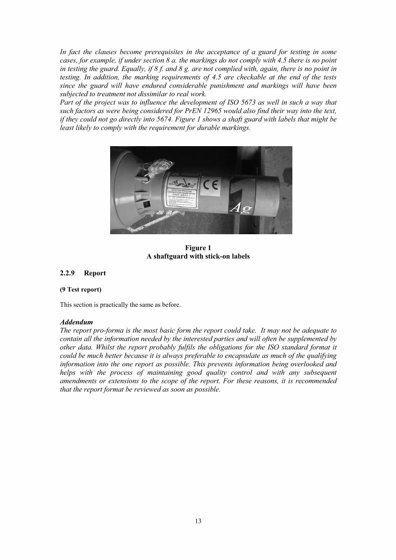
In fact the clauses become prerequisites in the acceptance of a guard for testing in some cases, for example, if under section 8 a. the markings do not comply with 4.5 there is no point in testing the guard. Equally, if 8 f. and 8 g. are not complied with, again, there is no point in testing. In addition, the marking requirements of 4.5 are checkable at the end of the tests since the guard will have endured considerable punishment and markings will have been subjected to treatment not dissimilar to real work. Part of the project was to influence the development of ISO 5673 as well in such a way that such factors as were being considered for PrEN 12965 would also find their way into the text, if they could not go directly into 5674. Figure 1 shows a shaft guard with labels that might be least likely to comply with the requirement for durable markings.
Figure 1 A shaftguard with stick-on labels
2.2.9 Report
(9 Test report)
This section is practically the same as before.
Addendum The report pro-forma is the most basic form the report could take. It may not be adequate to contain all the information needed by the interested parties and will often be supplemented by other data. Whilst the report probably fulfils the obligations for the ISO standard format it could be much better because it is always preferable to encapsulate as much of the qualifying information into the one report as possible. This prevents information being overlooked and helps with the process of maintaining good quality control and with any subsequent amendments or extensions to the scope of the report. For these reasons, it is recommended that the report format be reviewed as soon as possible.
13
2.2.10 Annexes
(Annex A Schedule of tests) EN 1152 does not have this but ISO 5674 needs it to show how the sequence of wear tests interacts with the various strength tests.
Rationale: The reasons for mingling the strength and wear test are dealt with above but decisions by VG7 of the CNB have introduced an interpretation on 23/6/1997. It states that the ESR (1): 1.5.4 must be addressed, therefore, dismantling and maintenance of the guard becomes part of the test at this point.
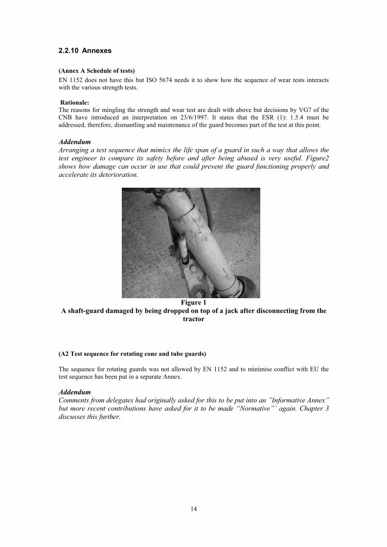
Addendum Arranging a test sequence that mimics the life span of a guard in such a way that allows the test engineer to compare its safety before and after being abused is very useful. Figure2 shows how damage can occur in use that could prevent the guard functioning properly and accelerate its deterioration.
Figure 1 A shaft-guard damaged by being dropped on top of a jack after disconnecting from the
tractor
(A2 Test sequence for rotating cone and tube guards)
The sequence for rotating guards was not allowed by EN 1152 and to minimise conflict with EU the test sequence has been put in a separate Annex.
Addendum Comments from delegates had originally asked for this to be put into an ”Informative Annex” but more recent contributions have asked for it to be made “Normative”’ again. Chapter 3 discusses this further.
14

(Annex B. (Informative) Cover type guard tests)
Rationale: Guards of novel design, particularly ‘concertina’ types are well known and represent a growing sector that is being subdued in its development because EN 1152 cannot be applied to it. Rather than continue to exclude those types of guard, a suggested method for testing them has been included in the standard. Research has enabled the development of this procedure and the principles of testing the more conventional guard have been applied where appropriate. There are guards emerging that combine the normal designs and versions of the ‘cover guard’ and it is hoped that test engineers can develop appropriate tests fore them using the principles outlined in 5674. Outlawing design innovation is not thought to be an option.
(Annex C. Test Report) The 1152 test report was modified to include the new tests.
(Annex D. UV Test for plastic guards) An example of how resistance to UV radiation can be evaluated by the manufacturer of a test body has been introduced.
Rationale: EN 1152 had mentioned the possible degradation of plastics due to Ultra Violet radiation. It was not thought to be acceptable to avoid the issue any longer and research was followed by the identification of this method for checking the resistance of the material to UV action. Research has shown that degradation of guards is a threat to their efficiency. The test is given as an example of how to comply with the requirement to give actual evidence on how the UV characteristics have been selected and how they will be checked in the future.
Essentially this is a Quality control issue and should be addressed by all manufacturers, especially when taking account of the need for conformity of production checking as a follow up to the initial assessment by the test agency. Furthermore, and importantly, the CNB vertical group 7 had issued on 24/09/96 a recommendation that to comply with ESR 1.5.11 “The manufacturer shall provide in the technical file a test report (according to national or international standard) concerning the resistance of the plastic to ultraviolet rays”
Addendum This research programme has not gone any further into this issue.
15

3. NEW TEST METHODS INCLUDING THE ADAPTATION OF TEST RIGS TO FOLLOW CEN RECCOMENDATIONS
The aim of this part of the work was to further adapt test rigs and carry out appropriate tests and trials to evaluate the principles of the strength tests which are being proposed in CEN. Investigate how they could be adapted to fit in with the latest version of ISO 5674 and taking into account the wear, damage and hazard problems identified by recent research, make proposals which are both suitable for the new ISO and as counter-suggestions for PrEN 12965. Particular attention was given to the subject of ‘adaptation to technical progress’ and current novel designs of guard (both on the shaft and on the tractor and machine) which seem to have been overlooked in the CEN proposals.
3.1 DYNAMIC SWIVEL TEST
3.1.1 Introduction
Appendix 1 was originally drawn up for the June 2001 Working Group meeting after researching the implications of the test in PrEN 12965 that the so-called ‘Dynamic Swivel Test’ is based on. It explains what is required during the tests. The moving of the radial loading point on the cone that is mentioned in 2.2.6 (6.3.1) above has an influence on the discussion regarding this point. See also Appendix 4.
3.1.2 Investigations
Initially, since the test procedure had come from another draft standard, it was necessary to find out if the techniques employed had been researched and if a working test rig had been made. It appears that no one has an automated rig to do these tests and only two organisations have made manually operated rigs to try out the procedures. One rig has been used by the Finnish testing institute at Vakola during a recent important investigation of the PTO shaft-guards currently in use in Finland (Report: “Conformity with the Machinery Directive of PTO shafts”; Matts Nysan, MTT/Agricultural Engineering Research (Vakkola)) in 2001.
Another rig has been used by GKN Walterscheid to check the guards it manufactures against the proposed standard. Pictures of both rigs, along with a prototype, automated rig, developed in the course of this research at SRI appear below (Figures 3, 4 and 5)
Having found that little work had been done elsewhere on the swivel test, construction of the SRI prototype automated rig was initiated. Several factors came to light in the course of that exercise such as:
· When the test body asks what is the manufacturers maximum operating angle? Is it the one for normal loaded operation, the one for use “intermittently”, the one specified by the shaft manufacturer in the case of retro-fit guards or something else? Will it be the angle printed on the guard, one printed in the handbook or one provided in some other literature?
· Should the test body to reflect possible miss-use increase the angle? It is evident that the angles quoted are very conservative and are much less than a driver would instinctively accept, especially for rotation at low power.
16

· Will the guard with the biggest cone be selected for test? The number of guards in a range usually tested is very low at the moment and this test could increase costs to manufacturers and therefore customers, who will then be less likely to renew guards.
· Could the need to pass this test result in designs of guard that are not ideal for the user, in much the same way as the current tests restrict innovation.
· Will the alterations to test equipment required for this test increase test costs dramatically and will the test rigs then be suitable for accreditation?
· No mention is made of the damage caused to cones contacting with the rear of the tractor master shield
A check of manufacturers instruction sheets revealed several ways of specifying the angles that the shafts should be used at. See Table 1 below.
Table 1 A selection of operating angles given in manufacturers instruction literature
Manufacturer Joint type Cont. operation Short Stationary angle duration angle
operation angle
Walterscheid Standard 25 45 90 Walterscheid Wide-angle 25 70/80 70/80 Aftakas Standard 25 Agdrive 35 Binacchi 35 Weasler Wide angle 80 cv joint 40 Weasler Wide angle 50 cv joint 30 Weasler Standard 30/540 RPM Weasler Standard 18/1000 RPM Bondioli & Pavesi
3.1.3 Recommendations
It is probable that this test can be made to work satisfactorily and even be accredited but the factors described above and in anticipation of others that have not yet come to light, it is likely that more discussion will be required. This should take place at the Working Group level and the findings must also be communicated to the Working Group developing PrEN 12965. The information gathered here will be added to more information that is due to be provided by some manufacturers and a solution will be sought.
The information about specified angles of operation will need to be provided in a more precise manner and manufacturers will have to negotiate with testing bodies to arrive at a satisfactory set of rules to cover this. The rules will probably have to be put in the Standard somehow.
17

Developing test rigs to accommodate wide angles will prove expensive as both ends of the rig will have to swivel more or less in unison. This is because the sum of the angles at each end must be as close as possible to zero or excessive vibration could result.
Fig 3 Swivel Test in Finland
Fig 4 GKN Swivel Rig
18

Fig 5 Automated Swivel Test at SRI (UK)
3.2 CHANGE OF POSITION OF RADIAL LOADING
3.2.1 Introduction
Before the working group meeting of June 2001, an investigation was carried out into the implications of the suggestion of moving the position of the radial load in ISO 5674. Appendix 4 is the review that was submitted to the group.
3.2.2 Investigation
In addition to the investigation covered in Appendix 4, some tests were carried out on manufacturers standard guards that were deliberately modified to simulate the designs that could result from the new test procedure. It must be pointed out that the guards used were never intended to be used in such a way by the manufacturers and if the models are recognised, they should be disregarded as ever being offered by the manufacturers in that form. The basis for the investigation was that if the test application position were moved it would be possible to produce cones of a much flimsier design. The implication of this may not be unfavourable as access could be improved but there is some evidence that cones that are more flexible might not be as durable as the more solid kinds. Fig. 6 below shows a guard that fulfils all the dimensional requirements and can pass a radial loading test to the new specification but has failed at the old position of loading. Again, it must be stressed that the manufacturer never designed the guard for this.
19

Figure 6 A cone modified to illustrate a failure mode
Another guard, shown in Fig. 7, was taken and the special reinforcing ring remove before being tested to the new radial loading instructions. It actually failed that test marginally but could easily be slightly re- designed to pass if required.
Figure 7 Another guard modified to support a theory
20
3.2.3 Recommendations
The implications of Appendix 4 have never been fully discussed and this will have to happen at the next Working group meeting.
The experiments with the more flexible cones will have to be discussed as well although it is difficult to speculate that they will be regarded as anything more than academic at this late stage in the development of the standard. There were several delegations who objected strongly to moving the load application point at an earlier phase of the standards development but they seem to have dropped their objections for the time being.
3.3 IMPROVEMENTS TO THE DYNAMIC AXIAL LOADING TEST
3.3.1 Introduction
In previous research programmes, it was decided to have a dynamic axial loading test for shaft guards. HSE Contract Research report No. 232/1999 showed how it was possible to achieve such tests in compression in a standard test rig. Discussions in the ISO working group developing ISO 5674 have led to the procedure being accepted and written into the latest DIS version. There has been some confusion about whether the axial tests should be conducted in tension as well as compression and some queries about the practicalities of the test. In addition to this, it has been pointed out that such test methods as are being proposed must be able to be checked for accreditation and calibration purposes. For these reasons, it was decided to carry out some further development of test rigs and methods and feed the information back to the Working Group.
3.3.2 Theory
Dynamic Axial Loading in tension as well as compression
· The original research had never advocated applying the axial loading in tension, it being ascertained that damage was most likely to be caused when a bearing was compressed.
· A guard bearing in compression could show no immediate outward signs of damage but then fail catastrophically anytime in the future.
· On the other hand, bearings subjected to tensional forces usually ‘popped out’ of their shaft grooves and it would be immediately evident that there was a failure. There was also some evidence that bearings were able to survive such separations without damage and could be re-assembled without impairing their performance in the future. Indeed, there was some suspicion that manufacturers were content that their designs allowed this to happen.
No further experiments on loading in tension were considered appropriate at this time although Appendix 3 is discussed in the conclusions to this section with reference to this topic.
Dynamic Axial Loading , rig specification, calibration and operation
(Adapting existing rigs and fixtures to do new tests is sometimes worse than designing from scratch.)
· The loading method and equipment must be capable of applying a predicted load in the right direction and on the correct part of the test item as laid down by the standard
21

· The load applied must be consistent over the duration of the test cycle and it must remain within certain tolerances and accuracy’s as laid down in the standard and as might be demanded by regulatory bodies accrediting the test equipment/methodologies
· For accredited test facilities, it is essential to prove that both the operating modes and calibration modes can be properly documented and assessments made of the fidelity of the tests and the uncertainty of measurements in all aspects of the rigs use
In the case of test equipment for strength testing according to EN 1152, the attention to the modern needs of measurement and calibration was fairly weak. One of the aims of developing the new DIS was to improve these aspects. The original test rigs as SRI were built using simple theories associated with dead weights and pulleys etc but even such seemingly simple systems are not free from systemic uncertainties, are susceptible to human error and may present safety problems for the testing staff however.
This project set out to design a system that could:
· Apply a predicted load in the direction required (compression only),
· Work for any normal design of telescopic shaft and guard (in a way that accounted for hysteresis effects)
· Be calibrated to a level that would be acceptable to an accreditation body.
The rig is pictured in Fig. 8, showing how an air ram is utilised to place a predicted axial load on the bearings as the shaft rotates at 1000 rev/min.
22

Fig. 8 Axial loading in the wear test rig
The use of loadcells is normally preferred to other methods of monitoring and recording loads these days but they are not ideally suited to the harsh conditions in a PTO shaft-guard test rig. Problems are experienced using loadcells in compression mode, particularly reading vibrating loads in widely varying temperatures. Earlier work had shown that air pressure systems were good for the application of steady loads in compression and that there were advantages from the fact that pressure regulators permit considerable springiness, which is never possible with dead weights or loadcells. On a rotating and vibrating system a rigid load can act like a hammer drill and damage components unrealistically. Previous research had shown that axial loading through the tubes of a shaft-guard jamming was likely to give a resilient load due to the tubes bending.
To compress the bearings, a method of attaching a ring of the same material as the outer guard tube to effectively make the outer tube too long has proved successful. It means that the tubes butt together well before the metal shaft bottoms out. Unless there is some unusual design factor present, this means that there is an equal force on each bearing in the axial direction, provided of course, that the tubes could slide relative to one another initially. If there was a great deal of friction, there might be a problem with this assumption but when the rig is rotating, it is assumed that such effects are negligible.
Measuring the load to be applied through a system comprising sliding shafts and linear bearings as well as the guard itself could be difficult to calibrate and to evaluate the uncertainties of measurement. However, the system that has been developed should minimise those effects.
23

In this case, a calibrated weight of the required 500N is always used to set up the load immediately prior to each test run. The loading system is always set up with the guard under test in situ and rotating, in this way, the forces to traverse the whole loading system and the guard itself are accounted for. With the guard ready in the rig and rotating as it would in the test, the calibrated 500N weight is attached to a cable that is pulled over a simple pulley whilst the air pressure is increased steadily in the pneumatic actuator. The shaft begins to close up and the weight steadily moves (without acceleration) to the limit set by the tubes with the collar attached. The pressure regulating valve remains set to that pressure whilst the air to the actuator is relieved via another valve, allowing the weight to return to rest, thereby extending the shaft again. It is easy and probably advisable, to traverse the system in a few times before the main set up run just to free the system up somewhat.
The weight is then detached from the cable and the test can begin. The regulator is used again to supply air without being adjusted and the force previously used to lift the weight is therefore applied as an axial load to the tubes and bearing.
The method takes account of the forces needed to push the rig and the effects on them of the rotation of the shaft.
3.3.3 Experiments
Dynamic Axial loading system
To provide evidence for discussion and to be evaluated against the needs of an accredited system, some test procedures were developed.
A set of runs was carried out with instrumentation in place to measure relevant parameters:
· A linear transducer was fitted to the actuator ram to measure distance moved so that it could be plotted against a time factor to make sure that loading was steady.
· A pressure transducer was tapped into the actuator supply line after the pressure regulator to give an accurate reading of pressure levels and fluctuations as the trials progressed.
· A weight of 500N was provided (in fact it was slightly more but served the purpose of the trials)
A series of five runs, with at least 3 replicates was carried out as follows:
i. The actuator was traversed in and out with no calibrated weight or PTO shaft and no rotation of the rig
ii. The same method was used but the calibrated weight was attached
iii. The weight was left on and the shaft (equipped with its guard) was attached
iv. As above but with the rig running at 1000 rev/min i.e. like the pre-setting for a proper test
v. As above but with the weight detached, i.e. as would be envisaged for a proper test run
A data-logger recorded the measurements and the raw data were incorporated in a spreadsheet for ease of analysis.
24
3.3.4 Results
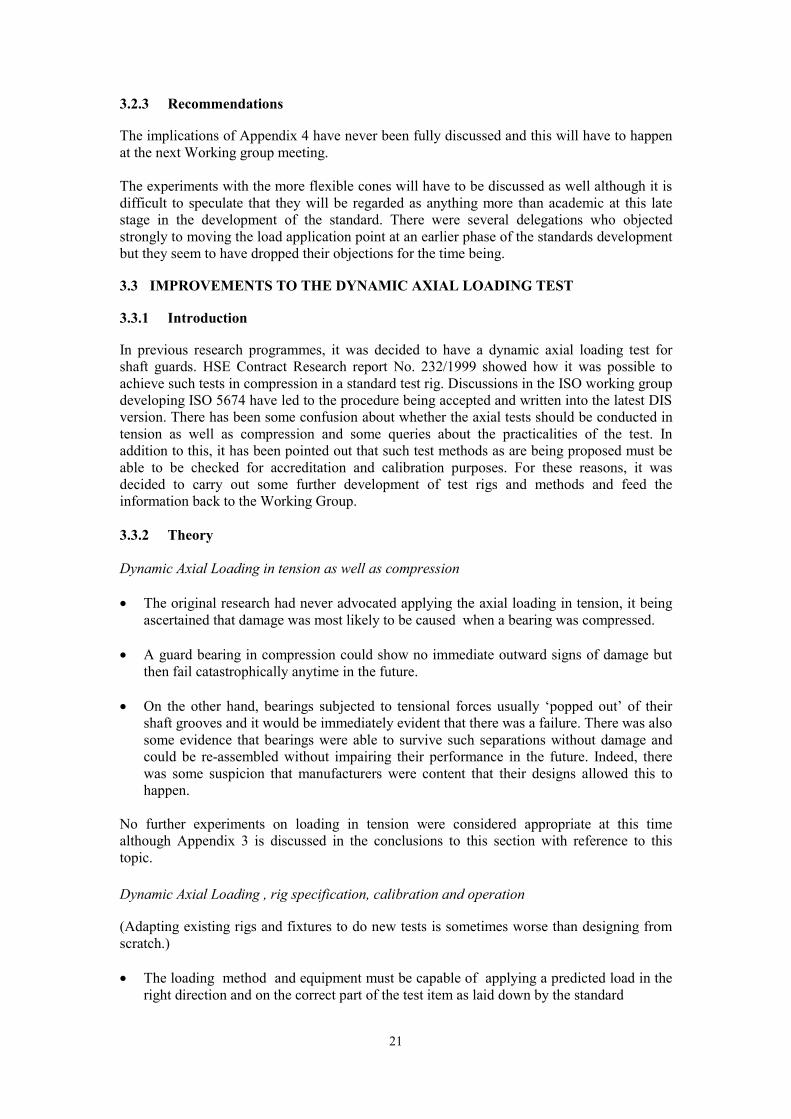
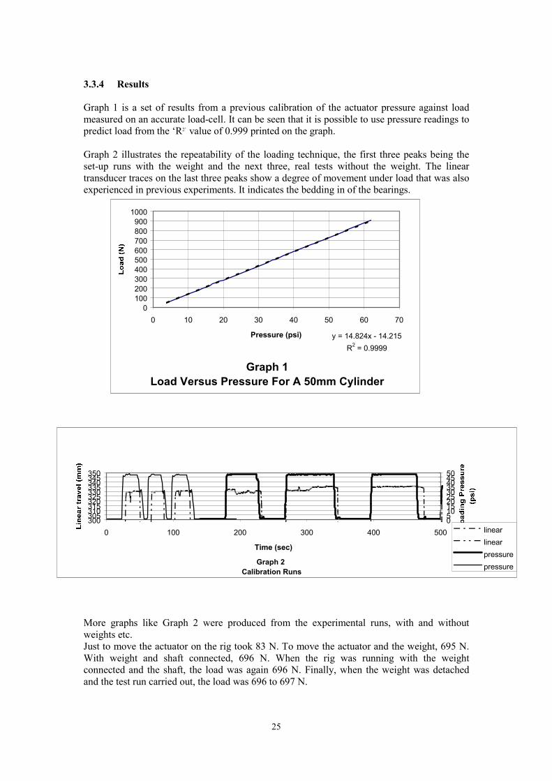
Graph 1 is a set of results from a previous calibration of the actuator pressure against load measured on an accurate load-cell. It can be seen that it is possible to use pressure readings to predict load from the ‘R2’ value of 0.999 printed on the graph.
Graph 2 illustrates the repeatability of the loading technique, the first three peaks being the set-up runs with the weight and the next three, real tests without the weight. The linear transducer traces on the last three peaks show a degree of movement under load that was also experienced in previous experiments. It indicates the bedding in of the bearings.
1000 900 800 700 600 500 400 300 200 100
0 0 10 20 30 40 50 60 70
Pressure (psi) y = 14.824x - 14.215 R2 = 0.9999
Graph 1 Load Versus Pressure For A 50mm Cylinder
Graph 2
300305310315320325330335340345350
0 100 200 300 400 500 05101520253035404550
linear linear
Calibration Runs
Time (sec) pressure pressure
More graphs like Graph 2 were produced from the experimental runs, with and without weights etc. Just to move the actuator on the rig took 83 N. To move the actuator and the weight, 695 N. With weight and shaft connected, 696 N. When the rig was running with the weight connected and the shaft, the load was again 696 N. Finally, when the weight was detached and the test run carried out, the load was 696 to 697 N.
25
3.3.5 Conclusions
Results that were previously submitted to the June 2001 Working Group meeting are to be found in Appendix 3 of this report. They were discussed and the option of removing the formula to calculate the load according to shaft size was adopted. The recommendation to upgrade the test loading to 700N was rejected on the grounds that some manufacturers were finding those limits too difficult to meet. Recent realisation that the standard asks for axial loading in both directions has prompted a re-think by this researcher. The delegates at the next Working Group meeting will be asked if their reasons for wanting a lower axial load was due to the difficulty of achieving 500 N in the tensile mode. If this is the case, a recommendation will be made to remove the requirement for tensile load and to increase the compressive load to 700 N.
A system has now been provided that can achieve the compressive load required by the standard. It applies to the SRI pneumatic system but has not been fully assessed in terms of its suitability for accreditation. This will be done at a later date.
The methodology will not necessarily apply to the systems used by other test bodies or manufacturers but the principles regarding calibration and accreditation of test rigs have been illustrated so that they can generate further discussion by the ISO working group. Manufacturers have also been carrying out tests on these methods but the results are not yet available for publication.
3.4 TESTS FOR ROTATING GUARDS
3.4.1 Introduction
In preparation for the June 2002 meeting of the Working Group the USA delegate prepared a proposal for a test of the immobilising torque for rotating guards.
Despite the fact that the EU Machinery Directive excludes rotating guards an ISO cannot do so if the guards are already being widely used, albeit outside the EU only.
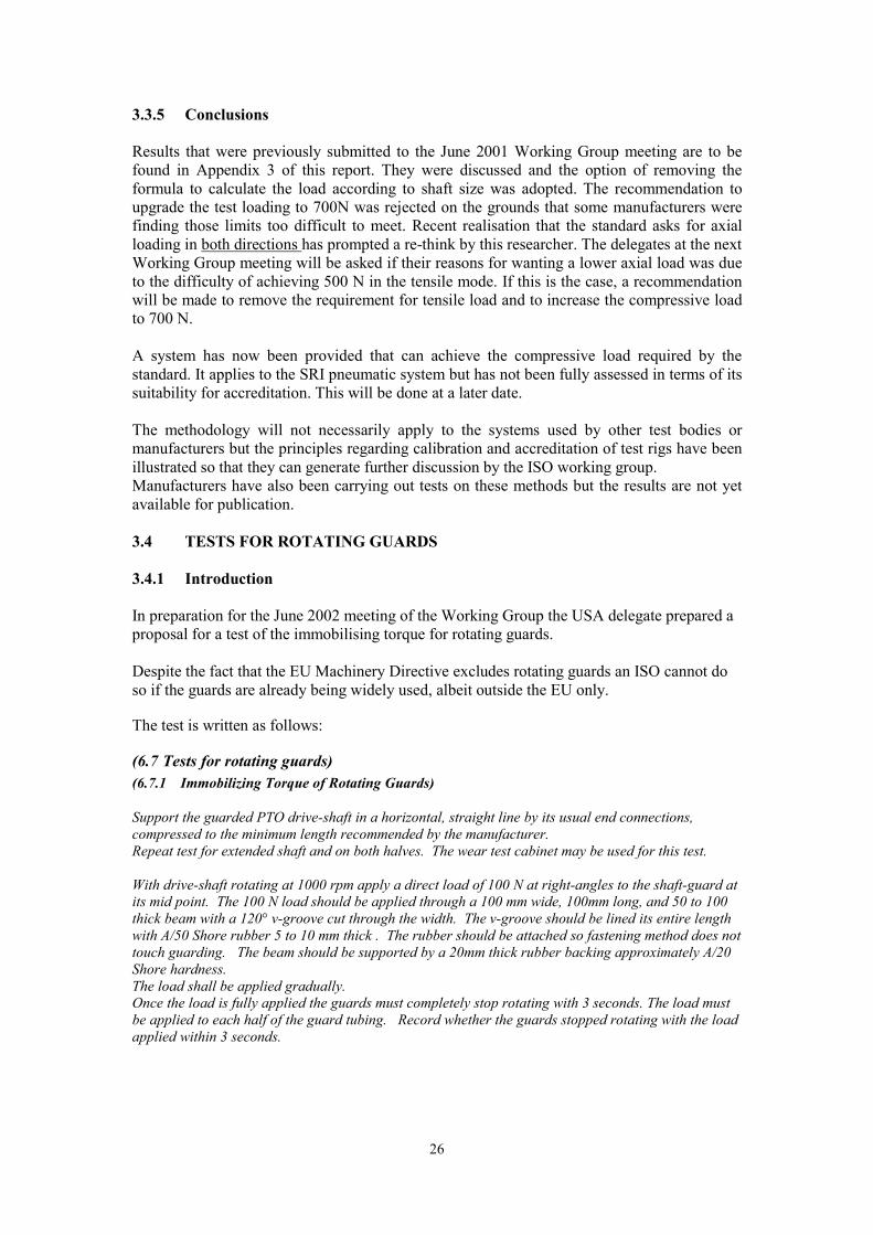
The test is written as follows:
(6.7 Tests for rotating guards) (6.7.1 Immobilizing Torque of Rotating Guards)
Support the guarded PTO drive-shaft in a horizontal, straight line by its usual end connections, compressed to the minimum length recommended by the manufacturer. Repeat test for extended shaft and on both halves. The wear test cabinet may be used for this test.
With drive-shaft rotating at 1000 rpm apply a direct load of 100 N at right-angles to the shaft-guard atits mid point. The 100 N load should be applied through a 100 mm wide, 100mm long, and 50 to 100 thick beam with a 120° v-groove cut through the width. The v-groove should be lined its entire length with A/50 Shore rubber 5 to 10 mm thick . The rubber should be attached so fastening method does nottouch guarding. The beam should be supported by a 20mm thick rubber backing approximately A/20 Shore hardness.The load shall be applied gradually. Once the load is fully applied the guards must completely stop rotating with 3 seconds. The load mustbe applied to each half of the guard tubing. Record whether the guards stopped rotating with the load applied within 3 seconds.
26

3.4.2 Analysis Of Rotating Guard Test Proposal
The following text was written as the UK response to the US proposal.
The method suggested for applying a braking force to the guard is practical and the apparatus is an adaptation of an existing rig, which makes economic sense but there are some major problems with its application in a test environment.
Reasons for wanting the test in the first place:
To prove that rotating guards will provide the protection they claim by stopping when coming into contact with: a. A person who might otherwise touch a rotating shaft, or
b. An object which might damage the guard itself if it continues to rotate and thus impair its efficiency to do a. above.
Identification of types of contact that could happen and how they could be transposed into realistic test methods:
The major types of contact identified by research are:
a. Pressing, leaning, grabbing, falling onto or standing on, all of which involve an element of tangential and radial force. Injury is then caused if the guard breaks up, exposing the rotating shaft or the guard itself causes abrasion.
b. Wrapping, where the rotating guard for example catches clothing. If the bearings do not allow the guard to stop soon enough, the person is pulled around and injured.
c. Wrapping of other items or crop can also cause damage by feeding it into the universal joint over as period of time.
Factors to be measured in a test to evaluate the level of protection offered in respect of the nature of the risks of injury outlined above:
a. Time taken to stop rotating. This involves the time that the inertia of the guard keeps it rotating and the amount of damage the guard itself can do to anyone coming into contact with it but also the amount of wrapping that can take place before it stops.
b. Force required stopping rotation. This involves the type of contact made, e.g. just a grabbing action from a hand as someone falls or some clothing wrapping round, both of these involve little radial loading.
c. Alternatively, the force can come from the whole weight of a person stepping onto the guard whereby the guard may stop quickly but damage may be done by exposure of the internal shaft due to friction after a very short period of time.
27

Comments · Review of the perceived dangers and analysis of whether currently proposed tests can
reveal the potential of tested guards to provide adequate protection.
· It is doubtful whether the test method proposed can be applied with adequate fidelity.
· The application of the load “gradually” would be difficult to control and open to varied interpretation.
· It gives little indication of the ‘wrapping’ potential because the braking force is not measured.
· The effect of weight on the guard is already measured in the radial loading tests.
· The 3 second stopping time would be difficult to measure and 3 seconds represents about 50 revolutions of the shaft at 1000 rev/min, 1or 2 of which would be enough to inflict serious damage to anyone having their clothes wrapped around the guard.
Suggestions for moving forward:
There must be a test of this type for rotating guards but a simpler form which concentrates on the tendency of the guard to stop when ‘wrapping’ or simple ‘grabbing’ may occur would be preferable. In previous suggestions for test US have tried to use a means of stopping the guard and measuring the torque required, then using the information to set pass-fail criteria based on the load and time data coming from that test. Unfortunately, the test method was found to be rather difficult to apply but another method is suggested below which could enable reversion to the original idea. The points of application and test conditions would remain largely as in the current draft but the actual braking of the tubes would be as follows.
Modified Test Method
Using the loadcell arrangement normally employed to measure chain loads (one that is not too susceptible to shock loads), a length of standard seat belting is attached which will hang down and be long enough to wrap 1.25 times around the tube of the guard. Using ‘hook and loop’ fastening materials, a band of the ‘loop’ type material is stuck to the parts of the guard that need to be tested (as defined in the current proposal). A piece of the ‘hook’ type material is securely attached to the face of the seat belt webbing at the end which is intended to stick to the tube. More ‘hook and loop’ material to holds the webbing in a loop around the tube, which allows it to rotate freely before reaching maximum speed. A piece of flat steel bar attached to the back of the webbing is fitted with a string to hold the arrangement clear of the rotating tube until the operator wishes the wrapping to commence. A chart recorder or similar device able to record load and time to an adequate degree is switched on and the restraining string is released, allowing the bar and webbing to swing into contact with the tube. The webbing will then wrap and the bar will swing clear of the tube as the restraining force is detected by the loadcell. Fig 9 shows the set-up.
28

This method has been tried with very repeatable success, measuring peak loads of around 300N and stopping times of about 0.03 seconds on a 70mm diameter tube.
The pass-fail criteria are not yet established but manufacturer data and experience coupled with some research could determine these in the near future.
Figure 9. A wrapping test for rotating guards
3.5 INCREASE IN TESTING TIME, EFFORT AND COST
It was always known that testing would be more time consuming and costly with the addition of the swivel test, the introduction of the axial loading tests and the mixing of the order of strength and wear tests. The extra costs should be justified in reducing the amount of injuries caused by inadequate guards. At this time the manufacturers are still evaluating the test procedures and have not produced sufficient data to truly assess the costs.
More data will be available at the July 2002 Working Group meeting and it should be possible to refine the test programme somewhat to eliminate unnecessary effort. The German delegation is working on this and will have a proposal for the meeting. Many of the comments in Appendix 2 refer to concerns of this kind and if some compromises can be found it is hoped that the SRI test rigs can be used to run a full test and find out what the real costs are. It must be said that there is a fear that if the costs increase too much, that less guards would be tested and that would not be desirable considering the very small number from each range that are tested at the moment.
29

30

APPENDIX 1
INTRODUCTION OF A TEST FOR DAMAGE AND CONTACT WITH THE STANDARD TRACTOR MASTER SHIELD
Background
EN 12965 is being developed to provide a better context for EN 1152, which is the EU equivalent to ISO 5674. 5674 has always had the benefit of ISO 5673 providing the information defining the shaft and guard, although it is currently being revised as it is out of date. Under the under the Vienna, agreement this committee has responsibility for future development of both ISO and CEN standards connected with this subject. It seems appropriate therefore, that any changes in either of the groups of standards should be embraced by the other standard until such time as they become truly harmonised. With this in mind, a test that has been included in 12965 was deemed to belong in 5674 provided that the delegates accepted the principles behind it. Although at a late stage in the development of N23, the test method was lifted from the 12965 text and ‘pasted’ into it.
Discussion
Some delegates had been involved in the development of 12965 and were happy that the principles were sound, however, other delegates had misgivings about the test and this has made it necessary to look closely at the proposed test before it can be accepted.
Comments to consider
· It is not desirable to introduce extra tests, which prolong the process of testing and increase the costs without sound evidence of the possible benefits.
· It is essential that all practical tests that determine whether a guard passes or fails are included in 5674.
· There is no point in going through with a test if the guard will not touch the master guard.
· The test only deals with lateral angularity and does not include pitch.
· The test will never reflect the misuse situation, which is the most likely time when damage occurs.
· The radial loading test on the cone already caters for the need to keep the cone robust.
· Wide angle and other special applications are the most susceptible to impinging on the Master Shield and there are other aspects of their guarding efficiency that also need to be included in this standard.
· Caution should be exercised when introducing any test into 5674 because it will become mandatory under the Machinery Directive if it is to replace EN 1152.
31
Solutions?
The advancement of the process of reviewing 5674 could be seriously affected by trying to include this section and perhaps even more parts of 12965 should be considered for inclusion, which would be even more of a hindrance. If this is a major consideration, then the whole section should be ignored for now. To include tests which are not well conceived would be a mistake.
Alternatively, there may be time to make changes that could also be used in 12965 if the research currently under way in UK and the results of the Finnish and other research could be harnessed relatively quickly.
In anticipation that the test could be improved, it would be sensible to change the text offered and have a section which calls for the guard to be placed within a Master Shield and an assessment made as to its likely contact. If it is adjudged that contact could occur that might cause damage then the test is carried out, if not …no need to test. The test would be part of an annex and not in the main part.
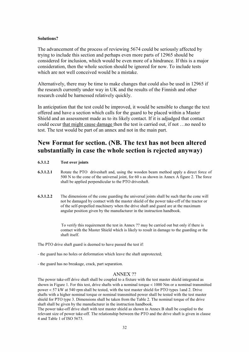
New Format for section. (NB. The text has not been altered substantially in case the whole section is rejected anyway)
6.3.1.2 Test over joints
6.3.1.2.1 Rotate the PTO driveshaft and, using the wooden beam method apply a direct force of 500 N to the cone of the universal joint, for 60 s as shown in Annex A figure 2. The force shall be applied perpendicular to the PTO driveshaft.
6.3.1.2.2 The dimensions of the cone guarding the universal joints shall be such that the cone will not be damaged by contact with the master shield of the power take-off of the tractor or of the self-propelled machinery when the drive shaft and guard are at the maximum angular position given by the manufacturer in the instruction handbook.
To verify this requirement the test in Annex ?? may be carried out but only if there is contact with the Master Shield which is likely to result in damage to the guarding or the shaft itself.
The PTO drive shaft guard is deemed to have passed the test if:
- the guard has no holes or deformation which leave the shaft unprotected;
- the guard has no breakage, crack, part separation.
ANNEX ?? The power take-off drive shaft shall be coupled to a fixture with the test master shield integrated as shown in Figure 1. For this test, drive shafts with a nominal torque < 1000 Nm or a nominal transmitted power < 57 kW at 540 rpm shall be tested, with the test master shield for PTO types 1and 2. Drive shafts with a higher nominal torque or nominal transmitted power shall be tested with the test master shield for PTO type 3. Dimensions shall be taken from the Table 2. The nominal torque of the drive shaft shall be given by the manufacturer in the instruction handbook. The power take-off drive shaft with test master shield as shown in Annex B shall be coupled to the relevant size of power take-off. The relationship between the PTO and the drive shaft is given in clause 4 and Table 1 of ISO 5673.
32
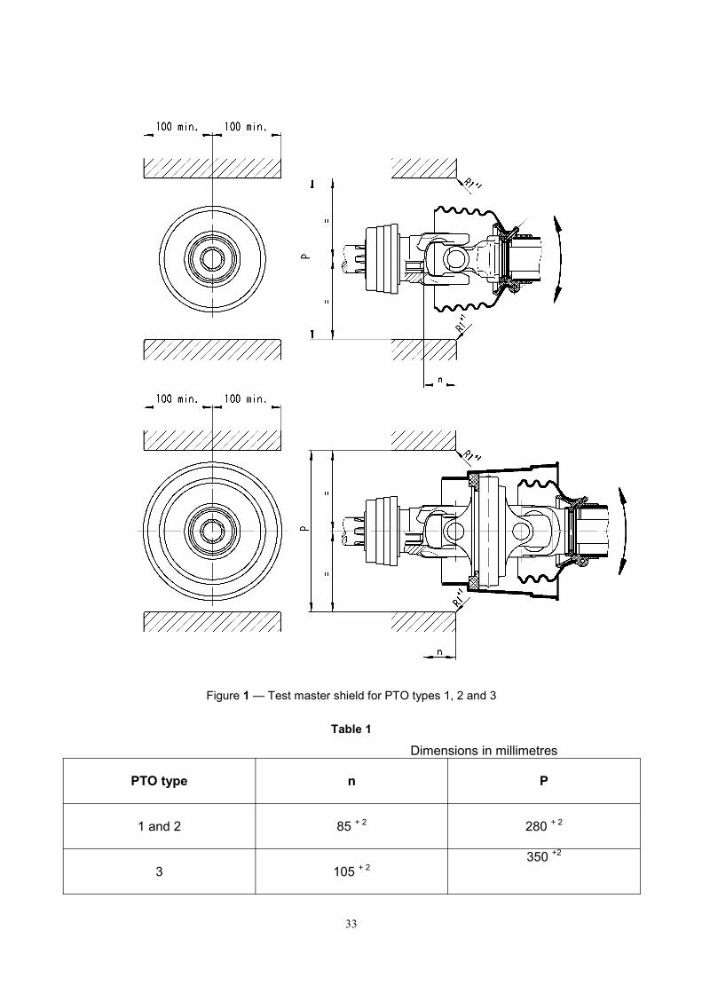
Figure 1 — Test master shield for PTO types 1, 2 and 3
Table 1
Dimensions in millimetres
PTO type n P
1 and 2 85 + 2 280 + 2
3 105 + 2 350 +2
33

The drive shaft and guard shall be moved from the in-line position in a horizontal plane to the maximum operational angle for universal and wide-angle universal joint as specified by the manufacturer in the instruction handbook and back. The relationship between the size of the drive shaft and the type of master shield shall be specified in the instruction handbook of the manufacturer.
The movement shall be with a dwell period of (5 ± 2) seconds at the maximum angle position. 100 cycles shall be completed in (15 ± 3) minutes.
34
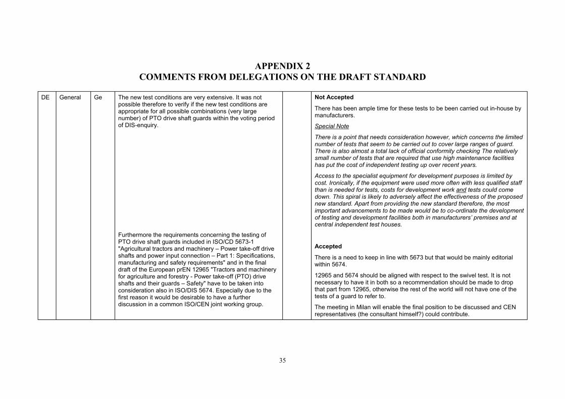
APPENDIX 2COMMENTS FROM DELEGATIONS ON THE DRAFT STANDARD
DE General Ge The new test conditions are very extensive. It was not possible therefore to verify if the new test conditions are appropriate for all possible combinations (very large number) of PTO drive shaft guards within the voting period of DIS-enquiry.
Furthermore the requirements concerning the testing of PTO drive shaft guards included in ISO/CD 5673-1 "Agricultural tractors and machinery – Power take-off drive shafts and power input connection – Part 1: Specifications, manufacturing and safety requirements" and in the final draft of the European prEN 12965 "Tractors and machinery for agriculture and forestry - Power take-off (PTO) drive shafts and their guards – Safety" have to be taken into consideration also in ISO/DIS 5674. Especially due to the first reason it would be desirable to have a further discussion in a common ISO/CEN joint working group.
Not Accepted
There has been ample time for these tests to be been carried out in-house by manufacturers.
Special Note
There is a point that needs consideration however, which concerns the limited number of tests that seem to be carried out to cover large ranges of guard. There is also almost a total lack of official conformity checking The relatively small number of tests that are required that use high maintenance facilities has put the cost of independent testing up over recent years.
Access to the specialist equipment for development purposes is limited by cost. Ironically, if the equipment were used more often with less qualified staff than is needed for tests, costs for development work and tests could come down. This spiral is likely to adversely affect the effectiveness of the proposed new standard. Apart from providing the new standard therefore, the most important advancements to be made would be to co-ordinate the development of testing and development facilities both in manufacturers’ premises and at central independent test houses.
Accepted
There is a need to keep in line with 5673 but that would be mainly editorial within 5674.
12965 and 5674 should be aligned with respect to the swivel test. It is not necessary to have it in both so a recommendation should be made to drop that part from 12965, otherwise the rest of the world will not have one of the tests of a guard to refer to.
The meeting in Milan will enable the final position to be discussed and CEN representatives (the consultant himself?) could contribute.
35

F general France disapproves this draft standard for the following reasons: 1. this standard is intended to be harmonised to comply with the Machinery directive
98/37/CE. Therefore, we cannot accept the possibility of having on the European level rotating guards;
2. even though there is a significant improvement on this draft considering the former versions, some very important points must be widely improved;
3. some additional requirements compared to EN 1152:1994 must at least be justified; a recent enquiry seems to show that issues met will not be solved by increasing guard strength;
4. implementation of some new tests does not seem to be that easy.
Furthermore, and even though they are not a justification for a disapproval, the following points have to be considered: ü compared to standard EN 1152, this draft describes tests, the implementation of
which will increase their duration to carry them out; ü new requirements may result in products which will be no more conform according
to the criteria whereas they are considered conform today. But it does not mean that safety will have been improved;
ü the cost of a guard complying with the requirements of this draft may be higher than the one of a guard complying with requirements of EN 1152. But there is no evidence that either its life duration or its efficiency will be really increased;
ü the text needs to have to its editing improved so that it can be more easily understood.
36

F 3.4 Editorial Replace « held stationary while the shaft is rotating » by « designed to be able to stay stationary while the shaft is rotating »
Accepted
HOWEVER the English would need to be better.
F 3.5 Technical This definition does not comply with the Essential Safety Requirements of Machinery directive 98/37/CE.
3.5 must be deleted. Possible discussion
The definition will be referred to in EN12965 and ISO5673.
Possible changes could be to 3.4 and 3.5 as follows:
3.4 Non-rotating PTO drive shaft guard: As defined by EN12965 and ISO5673
Otherwise, « which can rotate with the shaft » must be replaced by « designed to be able to rotate with the shaft »
3.5 Rotating PTO drive-shaft guard: As defined by ISO5673 only
Not Accepted
The definition given by France is not acceptable as it suggests that the guard is designed to rotate with the shaft but excludes the important feature that it stops when in contact with something
F 4.1.3 Editorial Complete the sentence by adding « in the instruction handbook » Not Accepted
It is accepted that the ‘Instruction book’ is not the only way that manufacturers’ instructions can be given. Add “e.g. in the instruction book”
Also, this clause actually states that it is necessary in some cases to contravene those instructions to carry out these tests.
F 4.1.4 Technical The length range is too small. Replace « between 1000 mm et 1010 mm closed length » par « between 900 mm et 1100 mm closed length »
Possible discussion
There has been ample opportunity to contribute other limits and there should be more evidence given for the 900mm figure. It is accepted that shafts with maximum lengths below 1000mm should not be excluded if they exist.
37
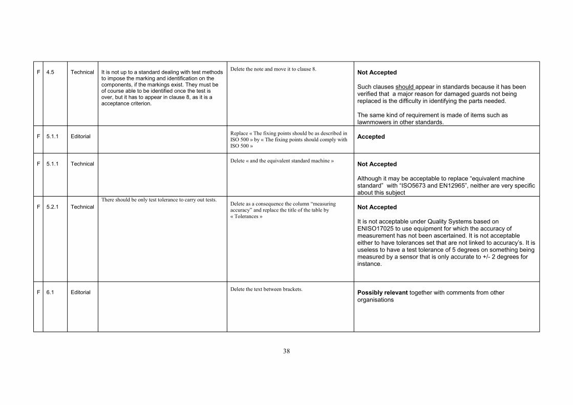
F 4.5 Technical It is not up to a standard dealing with test methods to impose the marking and identification on the components, if the markings exist. They must be of course able to be identified once the test is over, but it has to appear in clause 8, as it is a acceptance criterion.
Delete the note and move it to clause 8. Not Accepted
Such clauses should appear in standards because it has been verified that a major reason for damaged guards not being replaced is the difficulty in identifying the parts needed.
The same kind of requirement is made of items such as lawnmowers in other standards.
F 5.1.1 Editorial Replace « The fixing points should be as described in ISO 500 » by « The fixing points should comply with ISO 500 »
Accepted
F 5.1.1 Technical Delete « and the equivalent standard machine » Not Accepted
Although it may be acceptable to replace “equivalent machine standard” with “ISO5673 and EN12965”, neither are very specific about this subject
F 5.2.1 Technical There should be only test tolerance to carry out tests.
Delete as a consequence the column “measuring accuracy” and replace the title of the table by « Tolerances »
Not Accepted
It is not acceptable under Quality Systems based on ENISO17025 to use equipment for which the accuracy of measurement has not been ascertained. It is not acceptable either to have tolerances set that are not linked to accuracy’s. It is useless to have a test tolerance of 5 degrees on something being measured by a sensor that is only accurate to +/- 2 degrees for instance.
F 6.1 Editorial Delete the text between brackets. Possibly relevant together with comments from other organisations
38

F 6.1 Editorial The two last sentences must appear in subclause 4.1.
We propose to create a new subclause 4.1.5 « Results obtained from a sample can be applied to guards intended to shafts having a different minimum length. When a same guard can protect several shafts, it is possible to submit only the most unfavourable combination to tests. »
Discussion needed
The text could lead to confusion as ‘worst casing’ in the automotive field can lead to the production of a hybrid of parts, joined together for test purposes that would never appear in reality.
Worst casing should be left to the Notified body and the test undertaken to ISO5674 should be specific to the combination tested and different lengths with the same basic components.
F 6.1 Editorial Replace « For test sequence see annex A » by « Tests described in subclauses 6.2, 6.3, 6.4 and 6.5 shall be carried out according to the sequence of annex A »
Not accepted
F 6.2.2 Editorial The second paragraph requires the same thing as in 5.1.1 Delete the second paragraph. Accepted
BUT it is still acceptable to repeat things of such importance in order to emphasise them.
F 6.2.4.4 Editorial Change the title to « Corrosion test » Possible discussion point We do not understand the need to substitute the salt-
F 6.2.4.4 Technical water atomized solution test as described in EN 1152 by the corrosion test as it is proposed here, all the more as this new test deals only with the connection shaft/bush whereas the present test concerns the whole guard including restraining members. Experience shows that the salt-water atomized solution test is
Partial acceptance
It has been proven that the original test did not achieve the intended effect and the method described was almost impossible to ‘Quality Control’.
already rather selective. The application of spray on the outside of a well-greased guard could not achieve the same effect as a guard that had been ‘missused’ through lack of lubrication for example.
The restraining systems could not be at risk if only left for the designated 48 hours after the salt test. However, there would be some scope to allow the restraining system to be subject to the same salt water saturation at the discretion of the test authority, or even compulsorily if further support wase to come from other countries
39

F 6.3.1 Editorial The editing needs clarity, as it is difficult to understand properly the order of the tests. Furthermore, there is a numbering problem: 6.3.2 must become 6.3.1.1, etc.
Review the editing as well as the numbering of the text. Accepted
That editorial adjustments are needed
F 6.3.2.1 Technical It is sufficient to refer to Figure A.1.
Delete « to the cone of the universal joint » Not Accepted
EXCEPT that it should say “cone over the universal joint”
F 6.3.2.1 Technical We are not in favour of moving the application point of the load compared to the one given in EN 1152, i.e. apply the load at the centre of the cardan joint.
Take over the requirements given in EN 1152 concerning the application point of the load. Requires Discussion
Originally there was great opposition to moving this point and Finland wanted to make it even more rigorously selective to the point over the joint if possible.
F 6.3.2.1 Technical What is the interest to change the application point of the load during the test of the strength of the joints compared to the one given in EN 1152 ?
Take over the requirements given in EN 1152 concerning the application point of the load. See above
The implementation of the strength test on tubes seems F 6.3.3 Technical difficult. What is the advantage of the dynamic test Not Understood
compared to the static one ?
The numbering is not the same as N28 The sentence must be completed. Add at the end of the sentence « as represented in
F 6.3.3.2 Editorial annex A, figure A.1 »
F 6.3.3.3 Technical This is an acceptance criteria.
Move this requirement to clause 8. Accepted with comment
Acceptance criteria can be placed in the main text, as a reminder, if they have a specific bearing on the next phase of the test.
F 6.3.4 Editorial The first sentence must be moved after the second paragraph. Numbering seems to be confused here
F 6.3.4 Editorial Replace « fixture with the test master shield integrated » par « test equipment ». The word « master shield » must be replaced by « equipment » two more times in this paragraph.
Possible subject for discussion
Add at the end « and rotating at 1000 r/min » F 6.3.4 Editorial Accepted
At the end of 6.3.4, there are two acceptance criteria. Move these criteria to clause 8 F 6.3.4 Editorial Not relevant
40

F 6.3.5.1 Editorial Refer to figure A.1 of annex A
Accepted
F 6.3.5.2 Editorial Refer to figure A.1 of annex A
Accepted
F 6.3.6 Technical The implementation of this seems quite difficult (the application of a dynamic axial loading on a unit which is not perfectly aligned is difficult). What is the added value compared to the static test ?
Not Accepted (also the numbering is out of phase)
The added value is to address the findings of research that bearings push out of their grooves and are damaged, leading to danger in the future.
F 6.3.6 Technical Refer to figure A.1 of annex A
Accepted
F 6.3.6 Technical The note gives an acceptance criterion.
Move the note to clause 8 See previous comments
F 6.3.6 Technical Add a requirement to 6.3.6 explaining that the test must be carried out on each half drive shaft. Possible discussion point
F 6.4 Technical At low temperature, why does not the text propose to apply the same impact energy for drive shaft having a mass lower than 20 kg ?
Not Accepted
This has been discussed widely and good reasons offered
F 6.4.1.2 Editorial Replace « for 1 h » par « for at least 1 h » Possible discussion
The original test was not specific that the guard and shaft should actually be at – 35, rather that they should be placed in an atmosphere of –35 for 1hour prior to test. The true intentions of this test must be agreed.
F 6.4.1.3 Technical We understand neither the interest of making the impact energy vary with the mass of the drive shaft nor the choice of 20 kg as a limit. Furthermore, this proposal which gives a mass limit of 20 kg is not consistent with 6.1, which gives the possibility to extend test results to drive shafts with different minimum length.
We propose to take over the test of standard EN 1152 Not accepted
A worst casing process would make sure that no shaft over 20 kg could be covered by a test carried out at a lower ‘level’
HOWEVER an editorial note to explain what is required would be beneficial.
F 6.4.2.1 Editorial Replace « for 1 h » par « for at least 1 h » See above
41

F 6.5 Technical What is the use of this new requirement concerning the failing of the attachment of the restraining member on the attachment points of the guard ? How has the value of 600 N been chosen, beyond which the attachment must have failed ?
Take over the former version. Should this be 6.6?
Not Accepted
We have to come back to the former version which Much research has been done on this and the need for new requires to carry out two tests (a radial force must be applied in a plane perpendicular to the axis of the drive shaft and then a force of 400 N must be applied radially and tangentially to the drive shaft.)
attachment devices to prevent guard damage is widely accepted.
The level of 600 N has been questioned by Italy and may need further discussion however the figure was chosen because most guard restraining clips fail around 700 N. despite this, there are many guards being damaged at the attachment points, leading to further deterioration of the guard, therefore a failure load less than 700N would be beneficial.
F 6.5.2 Technical By accepting a replacement, we tend to see the circulation of numerous unrestrained guards (the restraining member may not be fitted again). Furthermore, this is an acceptance criterion.
Delete « (or replaced) » and move to clause 8 Not accepted
Permanent damage to restraining members leads to their lack of replacement and converts them to rotating guards or they are replaced by extra strong substitutes that allow the guards attachment points to be damaged.
There is a need to encourage designers to solve this problem and the standard must not block that process.
F 6.6 (new)
Technical Add a further clause 6.6, relating to the verification of indelibility of marking, as this is a very important issue. We propose to take over the method proposed by the
coordination of notified bodies (vertical group 7) and described in the file CNB/M/07.002
Accepted
Discussion required
F 7 Technical This clause applies only to rotating guards, which are forbidden by the European regulation. Delete this clause. Not accepted
Otherwise, the method must be modified, as it is not precise enough (the gradual application of the load must be defined for example by precising that it must go from a contact without any load to the maximum load in a given time)
HOWEVER the constructive comments about the test method are valid
Possible discussion?
F 8 Technical The first part does not have to appear in a standard giving a test method. Delete the first part. Possible discussion
42

F 8 Technical Precise that the markings must be legible but also present at the end of the test (if they were at the beginning)
Accepted
F 8 Technical The editing of EN 1152 is more precise for the measurement of the immobilization torque. We do not see the interest of limiting the sum of torques on each bearing.
Take over the editing of EN 1152 Accepted
Too complicated but also not technically accurate
F 8 Editorial For non-rotating guards, precise that the restraining members must be taken off to carry out the test. Not Accepted
It is quite possible to measure this by holding the chain or by clamping with some device that leaves the chain slack whilst measuring the torque.
F 8 Technical Replace this requirement by « the manufacturer has supplied evidence that plastic materials comply to the requirements of annex D ».
Possible discussion as Italy have raised objections also.
F 8 Technical This subject does not have to appear in a standard giving a test method. Delete.
F 9.1 Editorial There is a mistake in the reference.
Replace “clause 7” by “clause 8”.
F A.1 Editorial Add that this is carried out « according to manufacturers maintenance instructions given in the Accepted instruction handbook and rebuild. »
F A.1 Editorial The order of the test is not good.
Reverse 6.5.1.1 and 6.5.1.2. Possible discussion
F A.1 Editorial Figure A.1 must be updated to take into account the change of numbering. Possible discussion
F A.1 Editorial Modify the position of the application point of the radial load (see comment on 6.3.2.1) Possible discussion
F A.1 Editorial Complete the test of the restraining member (see comment on 6.5.1.1) Possible discussion
43

Delete A.2 concerning rotating guards F A.2 Technical Not Accepted
The first sentence is really difficult to understand. What We propose to replace this sentence by : « Any guards makes the specificity of this kind of guard is the lack of F B.1 Technical Possible discussion although the use of ‘risk’ is anathema to the which employ systems which are not linked to the bearings. US delegation drive shaft by one or several bearing(s) can be submitted to wear and strength tests dedicated to the risks to check, by using the test methods described in this standard. »
The other part of this is difficult to understand and We propose to delete it. dedicated to ‘TOTALGUARD’ F B.1 Technical Not Accepted
It is not dedicated to the Total Guard. It is using that concept to introduce the possibility of designs of guard, which can be different to those stereotypes given in the main body of the standard. This is for reasons of technical progress and possible better safety.
The test report should be completed by the description of maintenance operation, its periodicity, the type of F C Technical Possible Discussion grease or oil used, when applicable.
44
Change the status of annex D from informative to F D Technical normative
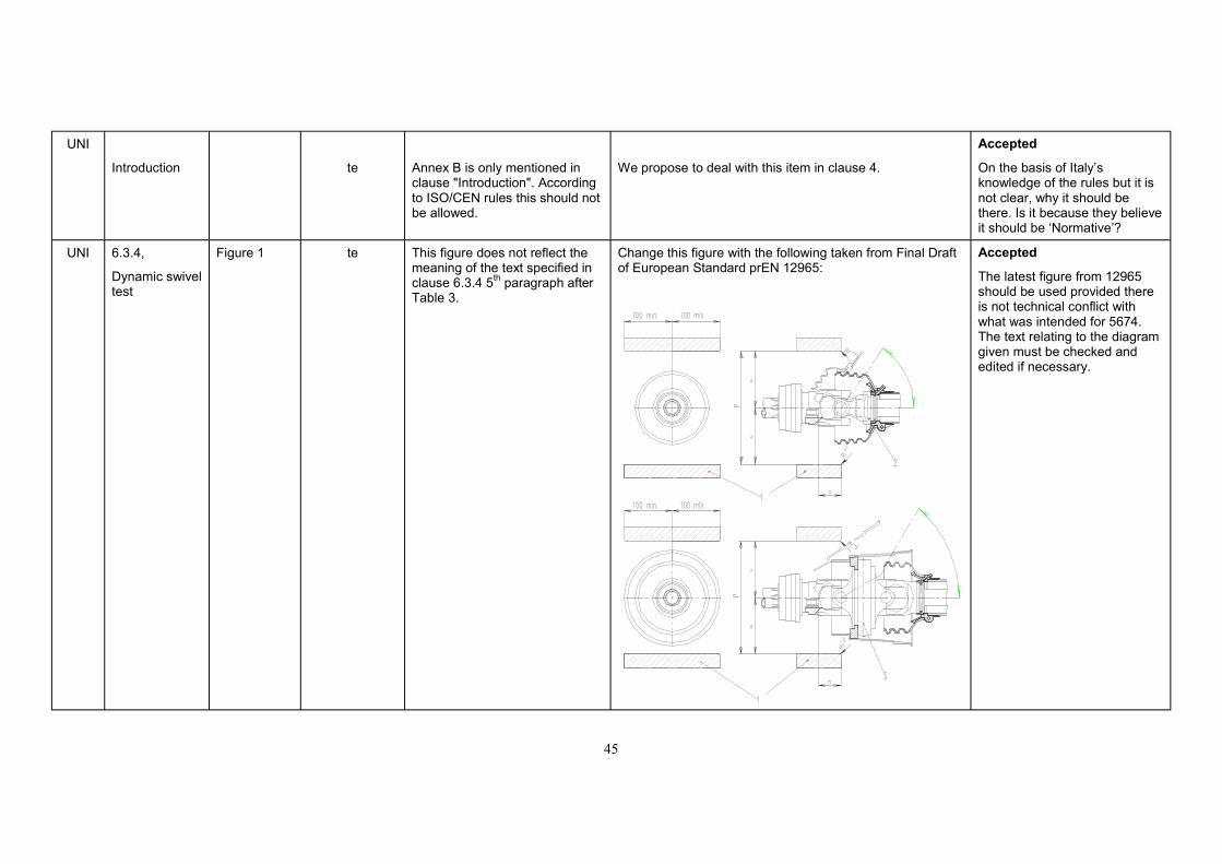
UNI
Introduction te
Annex B is only mentioned in clause "Introduction". According to ISO/CEN rules this should not be allowed.
We propose to deal with this item in clause 4.
Accepted
On the basis of Italy’s knowledge of the rules but it is not clear, why it should be there. Is it because they believe it should be ‘Normative’?
UNI 6.3.4,
Dynamic swivel test
Figure 1 te This figure does not reflect the meaning of the text specified in clause 6.3.4 5th paragraph after Table 3.
Change this figure with the following taken from Final Draft of European Standard prEN 12965:
Accepted
The latest figure from 12965 should be used provided there is not technical conflict with what was intended for 5674. The text relating to the diagram given must be checked and edited if necessary.
45

UNI Not Accepted
6.5.2 4th
sentence te The range between 400 N and 600 N as actually
in the text is too restrictive. We suggest increasing to 800 N the force at which the weak point of the restraining member shall fail.
The value of 800 N is beyond the failure load of ‘S’ clips that are widely used on guards now (they fail about 700 N usually). These guards are showing signs of breaking at the attachment points in the field so it is not a good idea to have a ‘pass level’ above 700 N
UNI Needs discussion
Annex B te If we well understand, this annex is only mentioned in clause "Introduction" and then is "informative". We do not agree with this way.
Annex B should be normative.
Some tests seems no to be appropriate to the type of guard dealt with.
We suggest to specify the type of shaft on which the "cover type guard" will be mounted.
We strongly want to avoid to use this guard with a drive shaft designed to be covered by a "standard" guard.
If consensus has gone back in the original direction, it would be desirable to have this part in the main body of the text again as ‘Normative’.
The specification of the type of shaft that this guard will be supplied for must remain within 12965 and 5673.
It is still under debate whether the standard is to be applied to guards ‘as supplied with shafts’, ‘replacement guards’, or what?
UNI
Annex D
We agree to have the mechanical test but not the colour test because the reference standard (ISO 105-A02) has another scope, not applicable to drive shaft guards.
We suggest to withdraw "colour test". Not Accepted
This subject was under review for long enough for manufacturers to agree on suitable measures.
As the Annex is ‘Informative’, the rules are optional. However, this subject should be treated as ’ongoing’ and the
46

About "Mechanical test" we intend to come back to this subject another time and propose an alternative test before next ISO/TC 23/SC 2/WG 5 meeting.
manufacturers must be encouraged to develop a suitable set of measures that they could perhaps make into a standard at some stage in the future. Unfortunately, the provisions as they are in this version of 5674 are not likely to put more pressure on the suppliers of the plastics for making the guards to provide better information to the guard manufacturers.
The mechanical tests are very minimal and could be improved.
Note.
It must be emphasised that these tests are meant to form part of a Quality Control scheme for manufacturers and it is assumed that most established producers would have systems that far exceed the very basic form described by the standard.
47

48

APPENDIX 3 FINAL ADJUSTMENTS TO DYNAMIC AXIAL TEST
Addendum
These interim proposals were produced for the June 2001 Working group meeting
The test title is also being queried and can probably be resolved quite simply.
The test has been accepted in principle but the final fixing of the loading values is still under debate however, results from UK research can be used to help in this decision.
The text as per latest N23:
6.3.3 Dynamic end loading tests of the bearings at ambient temperature.
6.3.3.1 With the PTO driveshaft and guard rotating in the wear test cabinet, or equivalent device, apply an axial force in both directions between the guard and the PTO driveshaft bearings for 60s.
The force shall be: a) 500N if the inner diameter of the outer guard tube, D is less than or equal to 80mm.
b) If the diameter D is more than 80mm, the load shall be determined by the formula F=Dx0.0125,
F being the axial force in kN up to a maximum of 1.5kN and the diameter D being in mm.
UK suggests the following solutions:
1. Change the title to ‘Dynamic axial loading tests of the bearings at ambient temperature.’
2. Consulting the results from UK research, the formula is of little value…… Quote: The proposed revised Standard as given in Appendix. 1 describes a workable method by which end-loads could be applied as part of a test programme. However, there is no evidence that the loading for the test should be based on a dimensional characteristic of the guard.
Therefore, a single load should be applied across the board.
3. The load suggested in the latest text shown above of 500N is probably too low because in the sample tested in UK, none of the guards was damaged at that load. The research report published did not deal with any degree of damage below 1.0kN but recent re-analysis of the results to look at the damage at several other stages of load between 500N and 1kN has produced the distribution graph below.
49
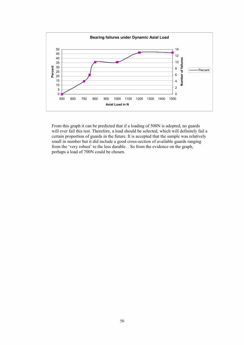
0 5
10 15 20 25 30 35 40 45 50
500 600 700 800 900 1000 1100 1200 1300 1400 1500 0
2
4
6
8
10
12
14
Bearing failures under Dynamic Axial Load
Axial Load in N
Perc
ent
Num
ber o
f fai
lure
s
Percent
From this graph it can be predicted that if a loading of 500N is adopted, no guards will ever fail this test. Therefore, a load should be selected, which will definitely fail a certain proportion of guards in the future. It is accepted that the sample was relatively small in number but it did include a good cross-section of available guards ranging from the ‘very robust’ to the less durable. . So from the evidence on the graph, perhaps a load of 700N could be chosen.
50
APPENDIX 4 REVIEW OF PROPOSALS TO MOVE RADIAL LOADING ON CONES
(SECTION 6.3.1.2.)
The most recent version of N23 ie. ISO 5674 DIS, has a new diagram with the position of the radial loading test being moved from over the centre of articulation of the u.j. to a point where the edge of the load application block is over that point.
This has caused some debate and has required the committee of WG5 to re-visit the basic principles upon which the test was based. The true criteria, which were applied in the original test, were not formally recorded but investigations into the UK records imply that the test was to reflect the situation whereby someone stepped on the shaft near the end. This could have been in a moment of forgetfulness or by his foot slipping off the tractor master shield, which was often used as a convenient step in the past. The universal joint was the most dangerous part of the shaft, so the test was made over that point.
This was duly embedded in ISO 5674 and became transferred to EN 1152 without question. At the same time, ASAE had a very similar standard but for some reason decided to apply load over the joint in a different place. Because everyone selling their shaftguards in Europe, including US manufacturers, had to comply with EN1152 and not many European manufacturers had to worry about complying with ASAE tests no-one raised the issue of the discrepancy. Now that there is a drive to harmonise ISO standards with ASAE and EU, the subject has been brought to the fore. To make everyone’s lives easier it would be convenient for ISO to adopt the same procedure as ASAE whenever possible because ASAE can officially replace its own standards with ISOs but not with EU directives or standards. At the same time, EU can adopt ISO standards but not ASAE. It seems likely that most of the proposals made to develop ISO5674 could be adopted by ASAE but the position of the radial load application over the u.j. might be something that could prevent them from agreeing to the whole document.
The initial reaction of many of the delegates was to say that the re-siting of the loading point would make the test less severe so it should be rejected, others contested that it was better to put load more over the bearings. Some suggested that the current test was wrong in concept because it was not necessary to load the guard on a point that was covered by the tractor Master Shield when in use anyway.
In order to check these assertions current and proposed versions of ISO5674, ISO5673, ISO500 and the proposed new PrEN12965 are being reviewed. The initial findings give cause for concern because there are some anomalies, which do not appear to have an easy solution. The situation is made even more complicated by the attempt to also include the test of the interference with the master shield from PrEN 12965 in the latest N23.
The logical premise that there is no need to apply a loading test to the part of the guard that is always inside the master shield of the tractor seems vindicated when illustrated in Fig 1 below. The guard shown is quite representative of several well known types and it can be seen that the block would not even rest on the cone if it was put at the first point which avoided the master shield! That is to say, the first point of contact for a foot next to the Master Shield.
As a means of comparison, the loading points specified by ISO, EN and ASAE are also illustrated. A secondary effect of this revelation is that the diagrams for the new test in section 6.3.1.2.1 are misleading. In addition, the dimensions given in PreN12965 do not tie up with the ones from ISO 500 with respect to the position of the master guard, the p.t.o. shaft end and the overlap of the master shield over the guard cone.
Provisional Conclusion The original test was either ill conceived or has become outdated due to the provision of larger Master shields on tractors. The consequences of having the test have been coincidental improvements in robustness of cones which has helped prevent damage (when in contact with master shields or
51
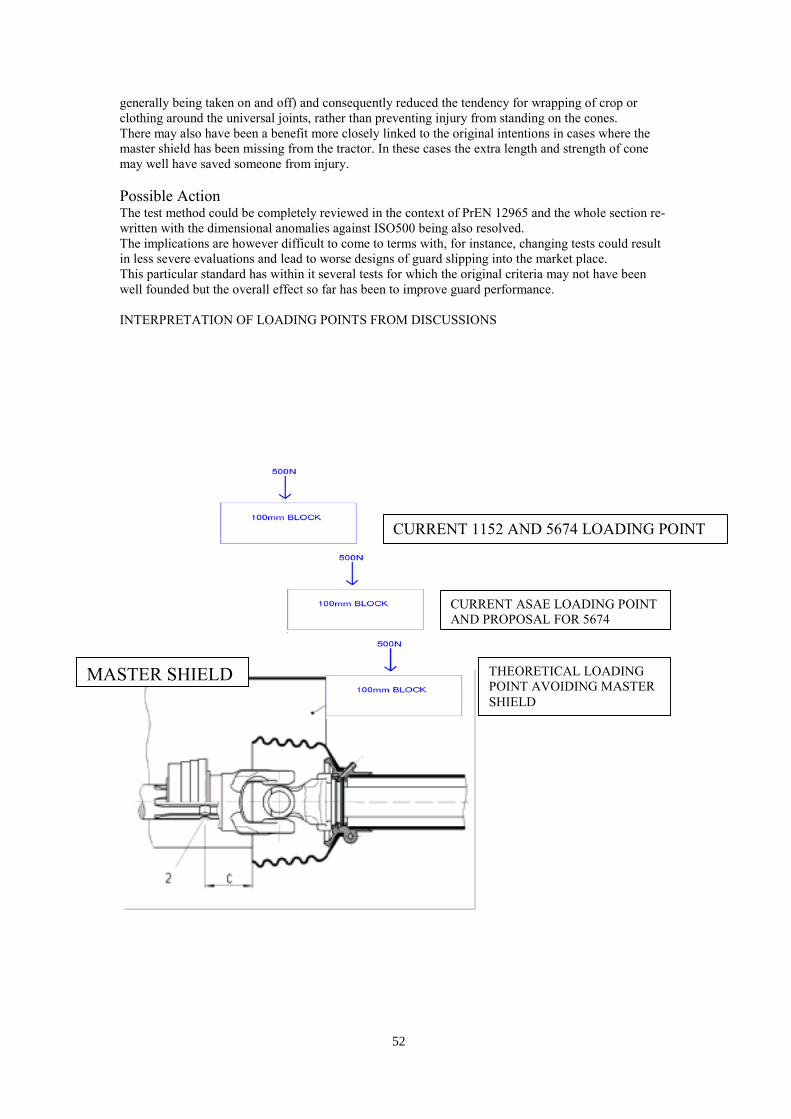
generally being taken on and off) and consequently reduced the tendency for wrapping of crop or clothing around the universal joints, rather than preventing injury from standing on the cones. There may also have been a benefit more closely linked to the original intentions in cases where the master shield has been missing from the tractor. In these cases the extra length and strength of cone may well have saved someone from injury.
Possible Action The test method could be completely reviewed in the context of PrEN 12965 and the whole section rewritten with the dimensional anomalies against ISO500 being also resolved. The implications are however difficult to come to terms with, for instance, changing tests could result in less severe evaluations and lead to worse designs of guard slipping into the market place. This particular standard has within it several tests for which the original criteria may not have been well founded but the overall effect so far has been to improve guard performance.
INTERPRETATION OF LOADING POINTS FROM DISCUSSIONS
CURRENT 1152 AND 5674 LOADING POINT52
CURRENT ASAE LOADING POINT AND PROPOSAL FOR 5674
THEORETICAL LOADING
MASTER SHIELD POINT AVOIDING MASTER SHIELD
53

Printed and published by the Health and Safety ExecutiveC1.25 12/02
ISBN 0-7176-2588-5
RR 051
780717625888£15.00 9