resident physics lectures christensen, chapter 5attenuation george david associate professor medical...
TRANSCRIPT
Resident Physics LecturesChristensen, Chapter 5
AttenuationAttenuation
George DavidAssociate ProfessorMedical College of GeorgiaDepartment of Radiology
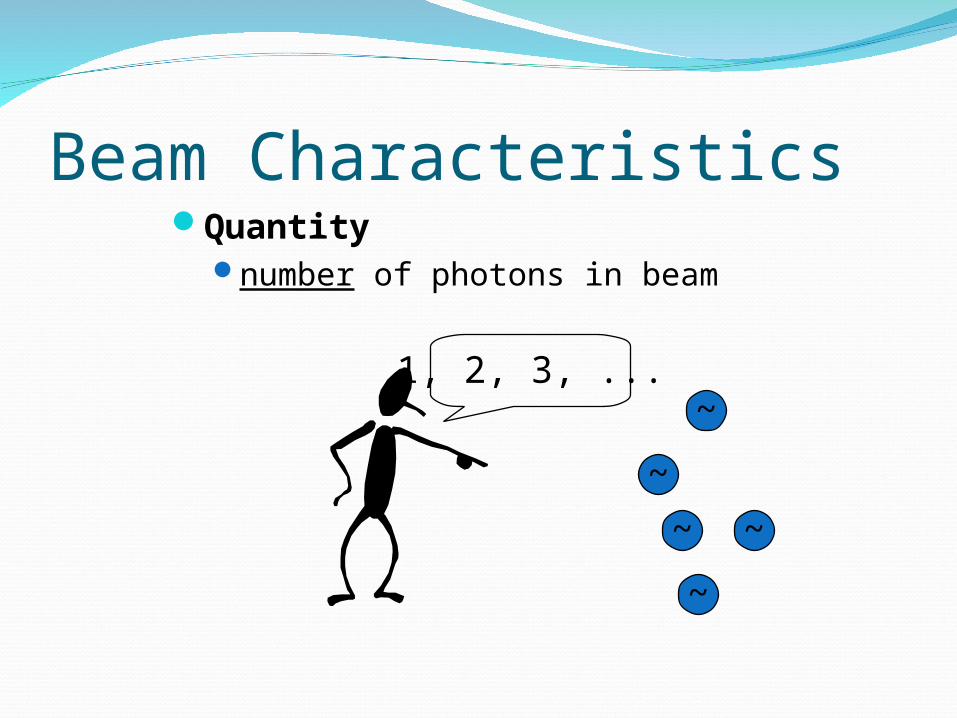
Beam CharacteristicsQuantity
number of photons in beam
~
~ ~
~
~1, 2, 3, ...
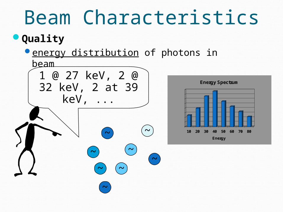
Beam CharacteristicsQuality
energy distribution of photons in beam
~
~
1 @ 27 keV, 2 @ 32 keV, 2 at 39 keV, ...
~
~
~
~
~
~
10 20 30 40 50 60 70 80
Energy
Energy Spectrum

Beam CharacteristicsIntensity
weighted product of # & energy of photons
depends on quantity quality
324 mR
~
~ ~
~
~
~~
~
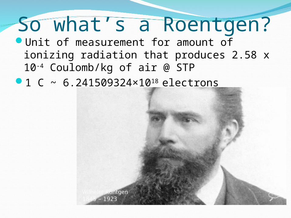
So what’s a Roentgen?Unit of measurement for amount of ionizing
radiation that produces 2.58 x 10⁻⁴ Coulomb/kg of air @ STP
1 C ~ 6.241509324×10¹⁸ electrons

Beam IntensityCan be measured in terms of # of ions created in air
by beamValid for monochromatic or for polychromatic beam
324 mR
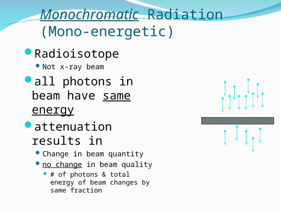
Monochromatic Radiation(Mono-energetic)
RadioisotopeNot x-ray beam
all photons in beam have same energy
attenuation results in Change in beam quantityno change in beam quality
# of photons & total energy of beam changes by same fraction
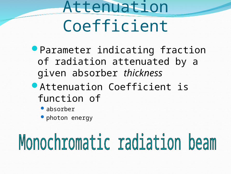
Attenuation CoefficientParameter indicating fraction of
radiation attenuated by a given absorber thickness
Attenuation Coefficient is function ofabsorberphoton energy
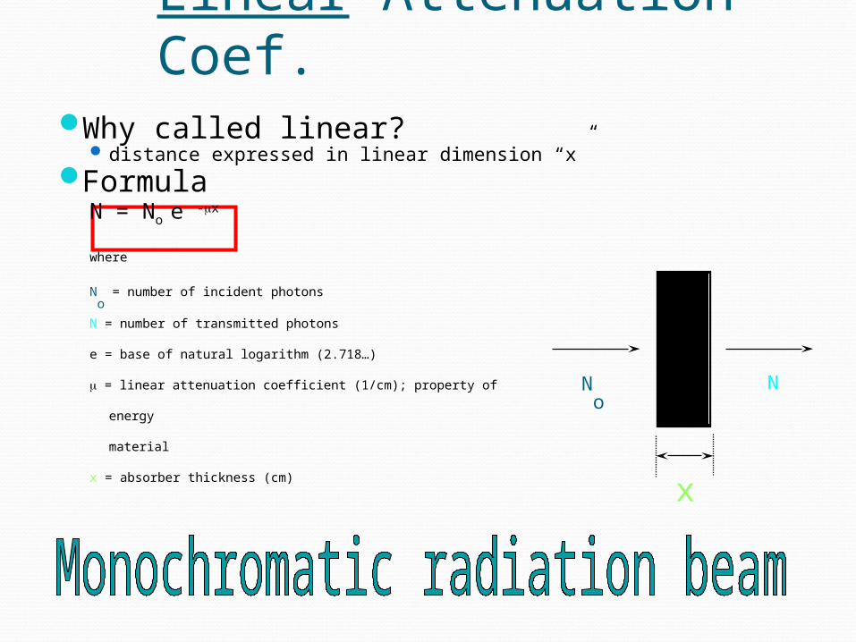
Linear Attenuation Coef.Why called linear?
distance expressed in linear dimension “x”Formula
N = No e -x
where
No = number of incident photons
N = number of transmitted photons
e = base of natural logarithm (2.718…)
= linear attenuation coefficient (1/cm); property of
energy
material
x = absorber thickness (cm)
No
N
x
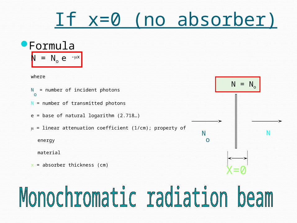
If x=0 (no absorber)Formula
N = No e -x
where
No = number of incident photons
N = number of transmitted photons
e = base of natural logarithm (2.718…)
= linear attenuation coefficient (1/cm); property of
energy
material
x = absorber thickness (cm)
No
N
X=0
N = No
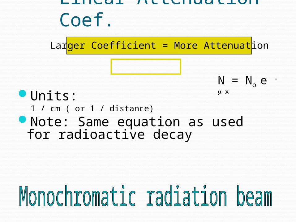
Linear Attenuation Coef.
Units:1 / cm ( or 1 / distance)
Note: Same equation as used for radioactive decay
N = No e - x
Larger Coefficient = More Attenuation
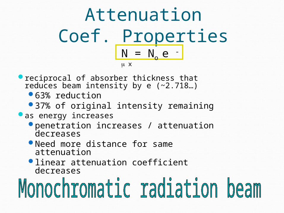
Linear Attenuation Coef. Properties
reciprocal of absorber thickness that reduces beam intensity by e (~2.718…)63% reduction37% of original intensity remaining
as energy increasespenetration increases / attenuation
decreasesNeed more distance for same
attenuationlinear attenuation coefficient decreases
N = No e - x
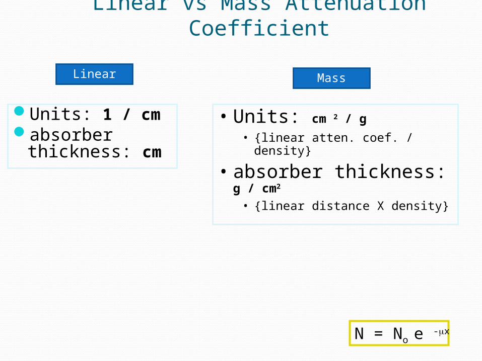
Linear vs Mass Attenuation Coefficient
Units: 1 / cmabsorber
thickness: cm
N = No e -x
• Units: cm 2 / g
• {linear atten. coef. / density}
• absorber thickness: g / cm2
• {linear distance X density}
Linear Mass
Mass Attenuation Coef.
Mass attenuation coefficient = linear attenuation coefficient divided by densitynormalizes for densityexpresses attenuation of a material
independent of physical stateNotes
references often give mass attenuation coef.
linear more useful in radiology
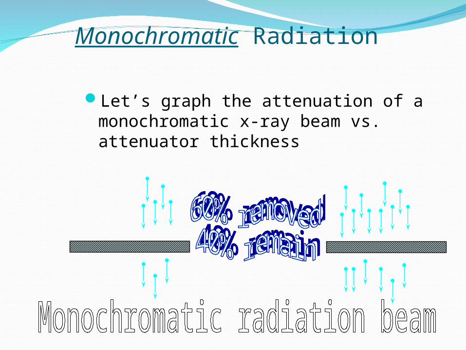
Monochromatic Radiation
Let’s graph the attenuation of a monochromatic x-ray beam vs. attenuator thickness
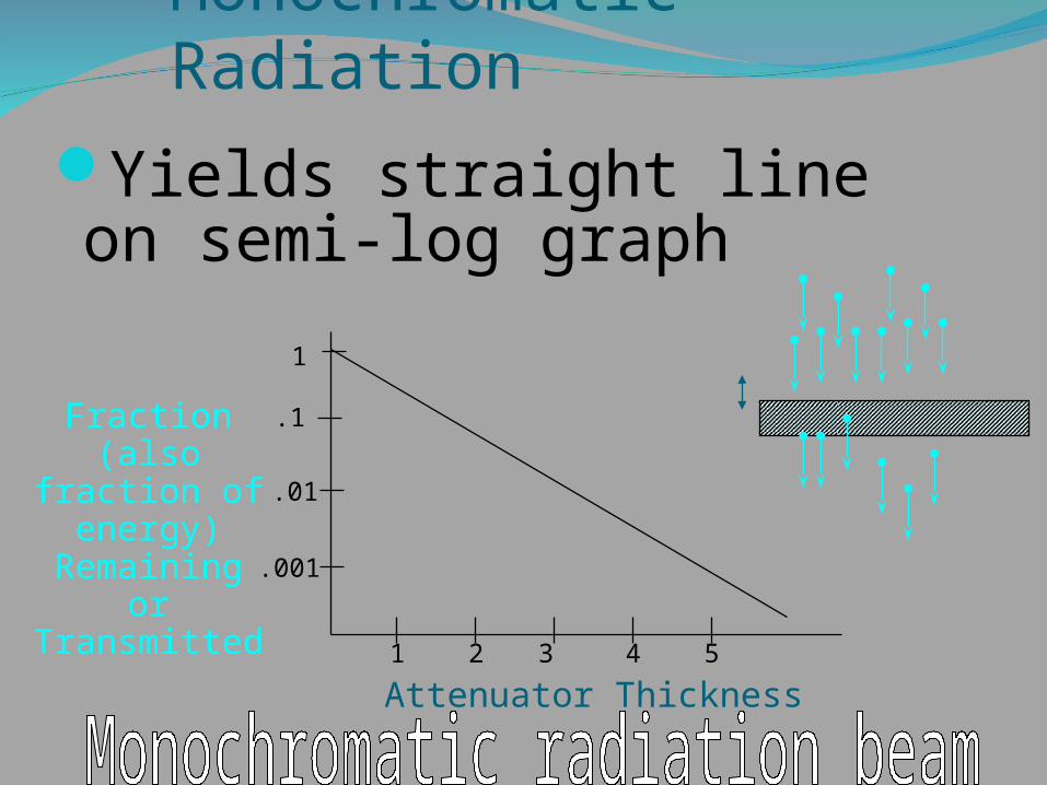
Monochromatic Radiation
Yields straight line on semi-log graph
Attenuator Thickness
Fraction(also fraction of
energy)Remaining or Transmitted
1
.1
.01
.001
1 2 3 4 5

Polychromatic Radiation(Poly-energetic)
X-Ray beam contains spectrum of photon energieshighest energy = peak kilovoltage applied to tubemean energy 1/3 - 1/2 of peak
depends on filtration
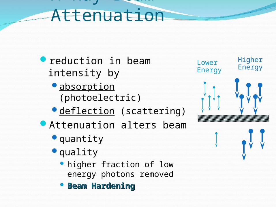
X-Ray Beam Attenuation
reduction in beam intensity byabsorption (photoelectric)deflection (scattering)
Attenuation alters beamquantityquality
higher fraction of low energy photons removed
Beam HardeningBeam Hardening
HigherEnergy
LowerEnergy
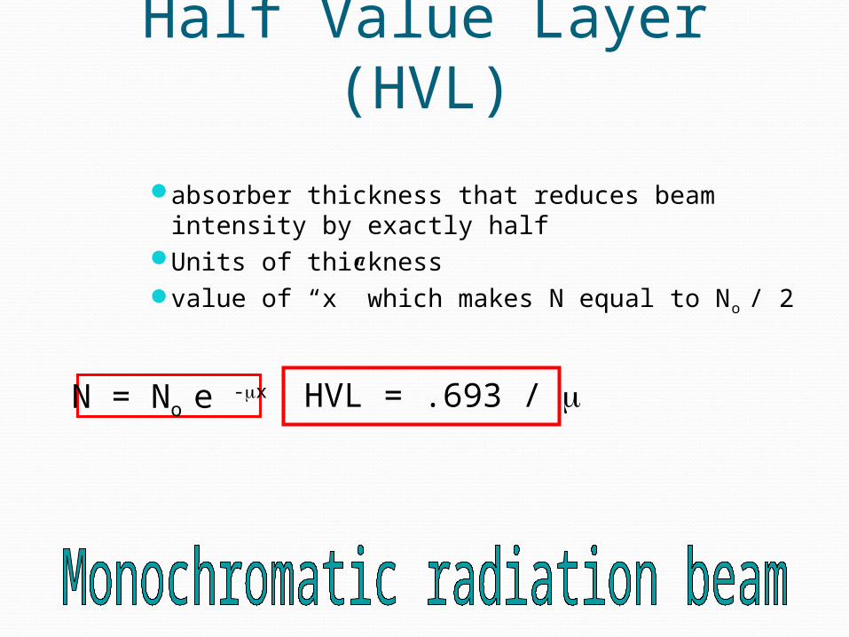
N = No e -x HVL = .693 /
Half Value Layer (HVL)
absorber thickness that reduces beam intensity by exactly half
Units of thicknessvalue of “x” which makes N equal to No / 2
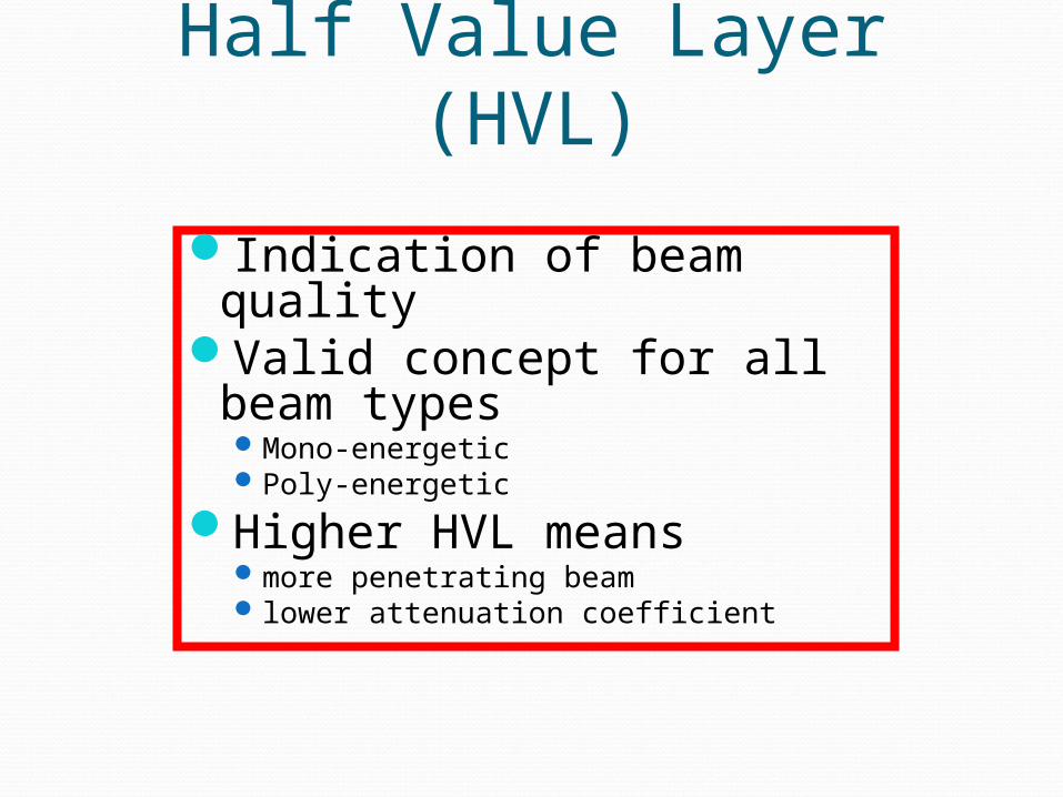
Half Value Layer (HVL)
Indication of beam qualityValid concept for all beam
typesMono-energeticPoly-energetic
Higher HVL meansmore penetrating beam lower attenuation coefficient

Factors Affecting Attenuation
Energy of radiation / beam qualityhigher energy
more penetration less attenuation
Matterdensityatomic numberelectrons per gramhigher density, atomic number, or electrons
per gram increases attenuation
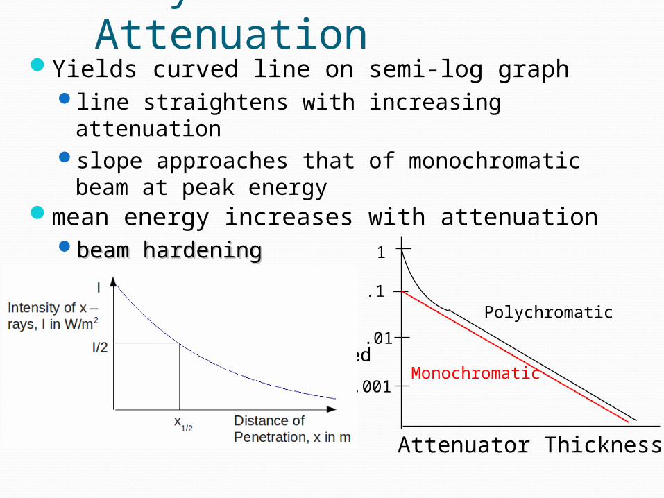
Polychromatic AttenuationYields curved line on semi-log graph
line straightens with increasing attenuationslope approaches that of monochromatic beam
at peak energymean energy increases with attenuation
beam hardeningbeam hardening
Attenuator Thickness
1
.1
.01
.001
FractionTransmitted
Monochromatic
Polychromatic
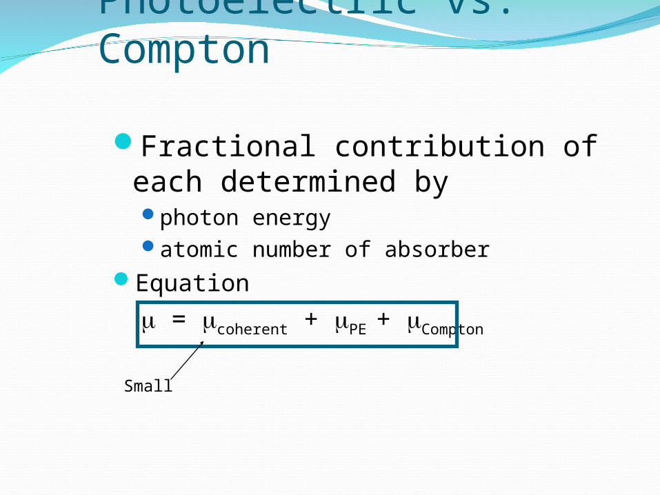
Photoelectric vs. Compton
Fractional contribution of each determined byphoton energyatomic number of absorber
Equation
= coherent + PE + Compton
Small
Attenuation & Density
Attenuation proportional to densitydifference in tissue densities accounts
for much of optical density difference seen radiographs
# of Compton interactions depends on electrons / unit pathwhich depends on
electrons per gram density
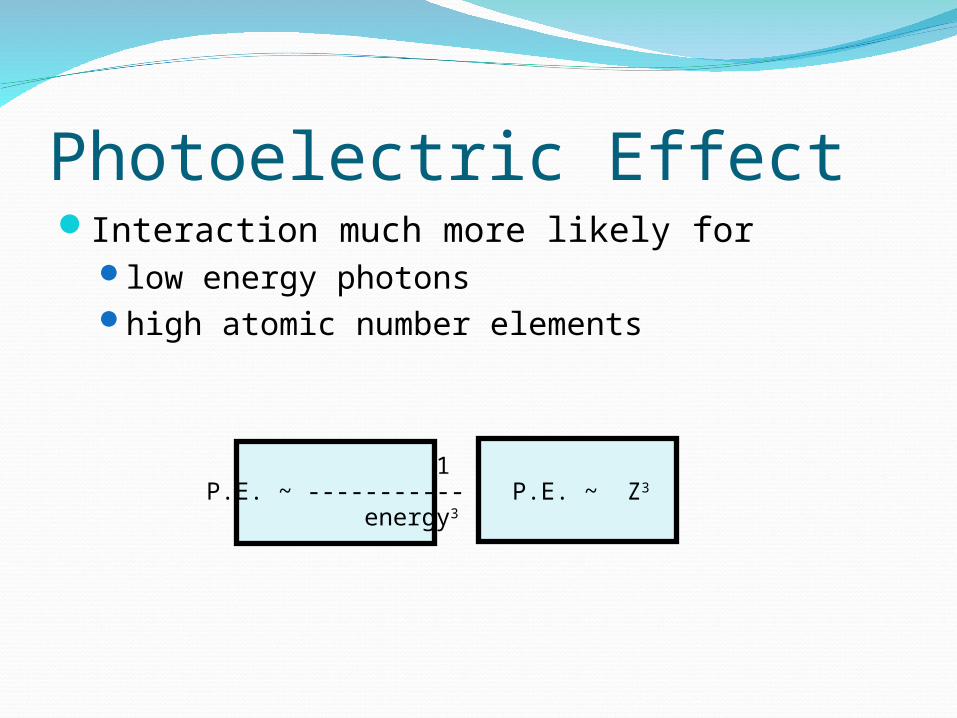
Photoelectric EffectInteraction much more likely for
low energy photonshigh atomic number elements
1P.E. ~ ----------- energy3
P.E. ~ Z3
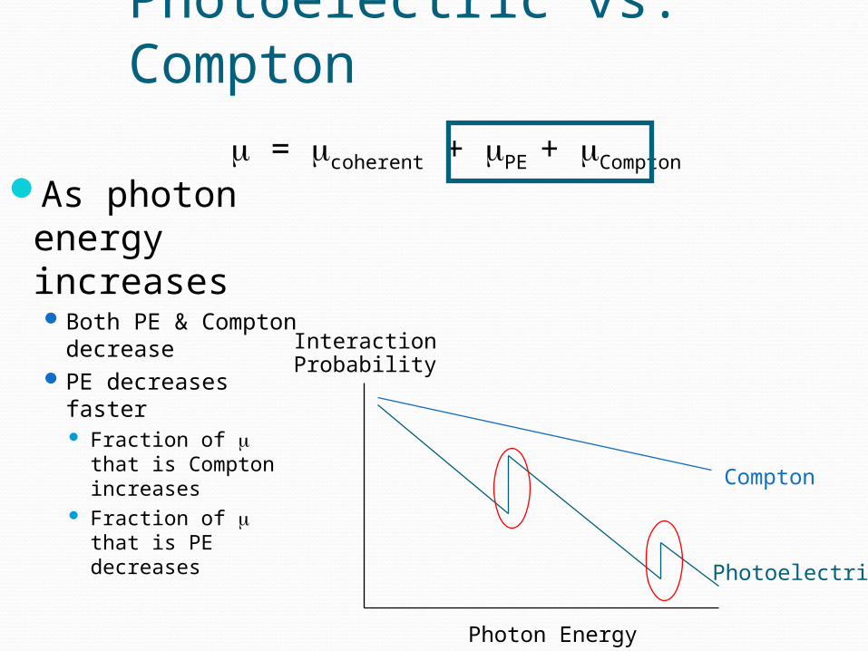
Photoelectric vs. Compton
As photon energy increasesBoth PE &
Compton decreasePE decreases
faster Fraction of that
is Compton increases
Fraction of that is PE decreases
= coherent + PE + Compton
Photon Energy
InteractionProbability
Compton
Photoelectric
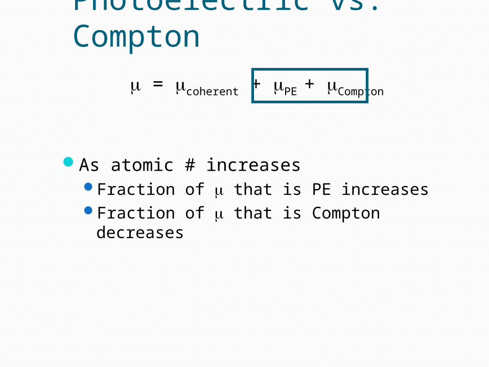
Photoelectric vs. Compton
As atomic # increasesFraction of that is PE increasesFraction of that is Compton decreases
= coherent + PE + Compton
Photoelectric
Compton
PairProduction
Photon Energy
AtomicNumber of Absorber
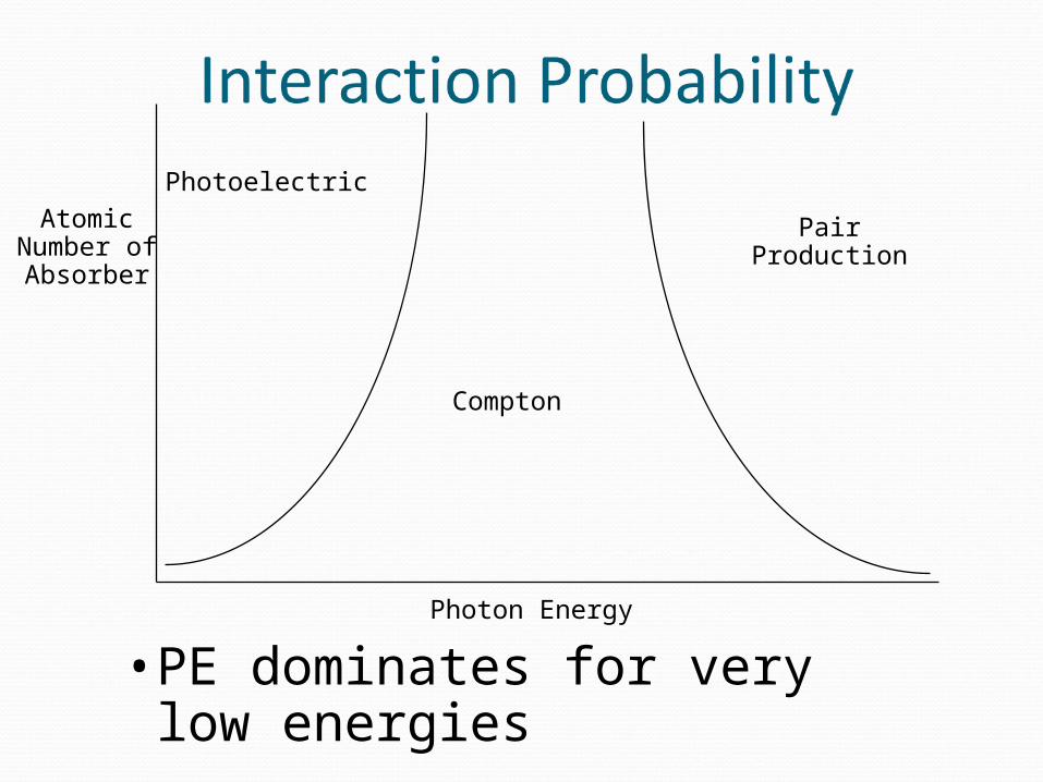
• PE dominates for very low energies

Photoelectric
Compton
PairProduction
Photon Energy
AtomicNumber of Absorber
• For lower atomic numbers– Compton dominates for high energies
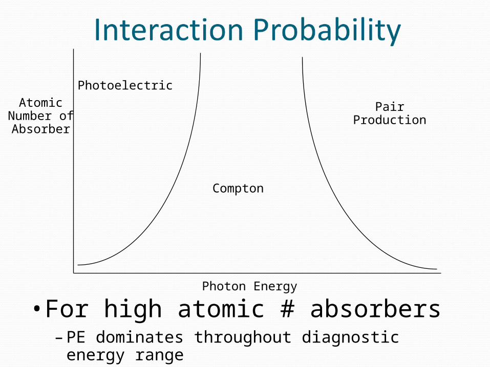
Photoelectric
Compton
PairProduction
Photon Energy
AtomicNumber of Absorber
• For high atomic # absorbers– PE dominates throughout diagnostic energy range
RelationshipsDensity generally increases with atomic
#different states = different density
ice, water, steamno relationship between density and
electrons per gramatomic # vs. electrons / gram
hydrogen ~ 2X electrons / gram as most other substances
as atomic # increases, electrons / gram decreases slightly

ApplicationsAs photon energy increases
subject (and image) contrast decreasesdifferential absorption decreases
at 20 keV bone’s linear attenuation coefficient 6 X water’s
at 100 keV bone’s linear attenuation coefficient 1.4 X water’s
0102030405060708090
100
20 keV 100 ke
Bone
Water
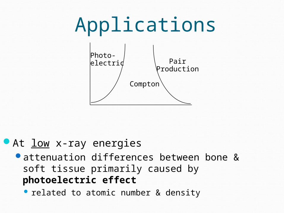
Applications
At low x-ray energiesattenuation differences between bone & soft
tissue primarily caused by photoelectric effect related to atomic number & density
Photo-electric
Compton
PairProduction

Applications
At high x-ray energiesattenuation differences between bone & soft
tissue primarily because of Compton scatter related entirely to density
Photo-electric
Compton
PairProduction
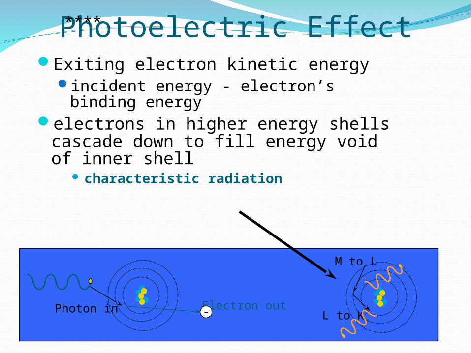
Photoelectric EffectExiting electron kinetic energy
incident energy - electron’s binding energy
electrons in higher energy shells cascade down to fill energy void of inner shell
characteristic radiation
Electron outPhoton in
M to L
L to K-
****

K-EdgeEach electron shell has threshold for PE
effectPhoton energy must be >= binding energy
of shell For photon energy > K-shell binding energy, k-
shell electrons become candidates for PEPE probability falls off drastically with
energySO
PE interactions generally decrease but increase as photon energy exceeds shell binding energies
1P.E. ~ ----------- energy3
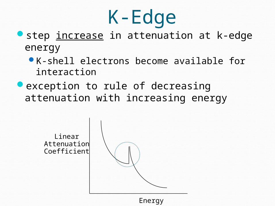
K-Edgestep increase in attenuation at k-edge energy
K-shell electrons become available for interaction
exception to rule of decreasing attenuation with increasing energy
Energy
LinearAttenuationCoefficient
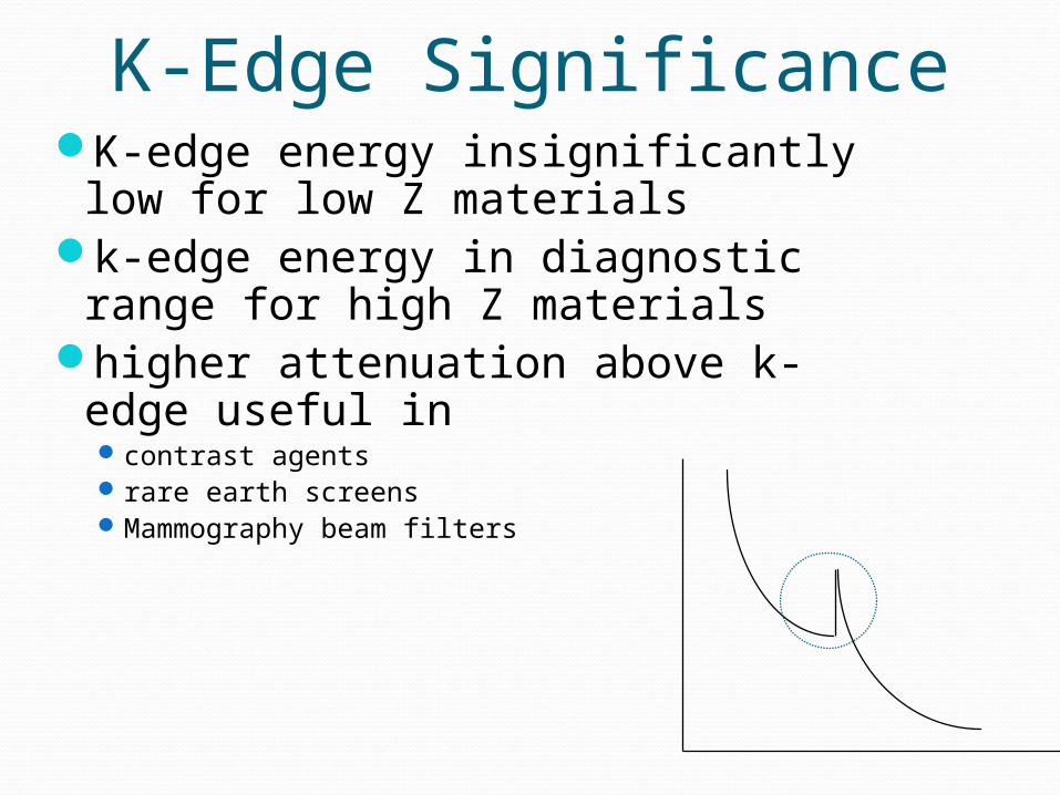
K-Edge SignificanceK-edge energy insignificantly
low for low Z materials k-edge energy in diagnostic
range for high Z materialshigher attenuation above k-
edge useful incontrast agentsrare earth screensMammography beam filters
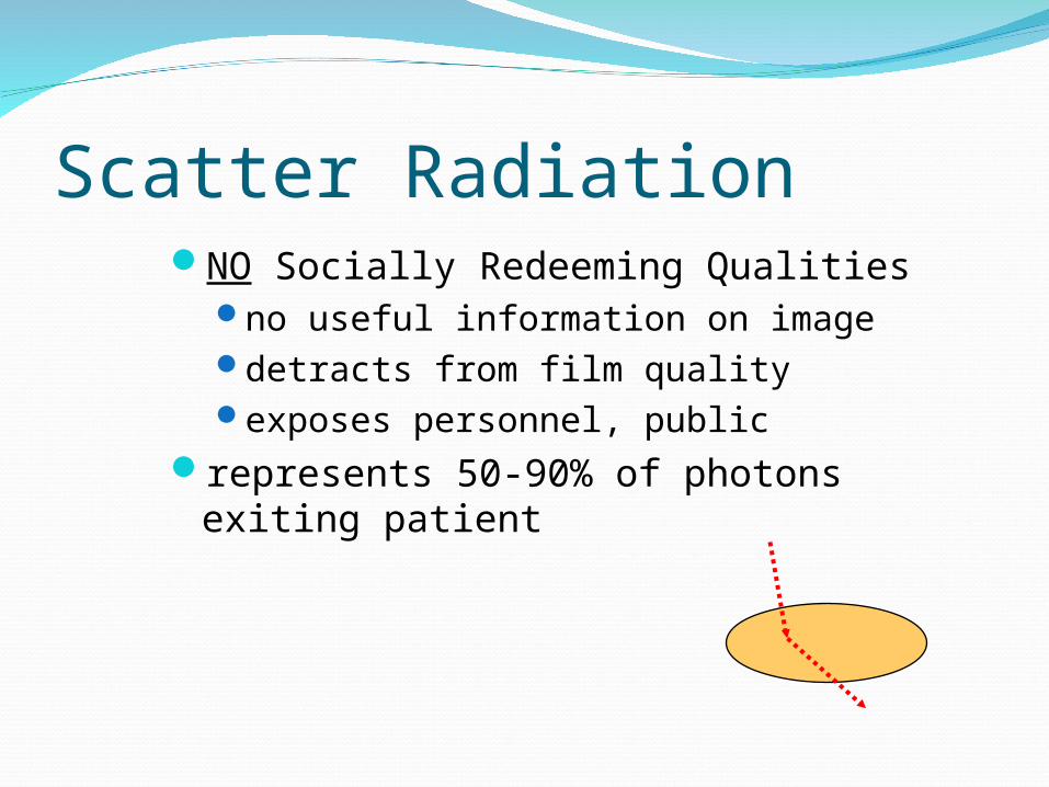
Scatter RadiationNO Socially Redeeming Qualities
no useful information on imagedetracts from film qualityexposes personnel, public
represents 50-90% of photons exiting patient

Abdominal Photons~1% of incident photons on adult abdomen
reach filmfate of the other 99%
mostly scatter most do not reach film
absorption
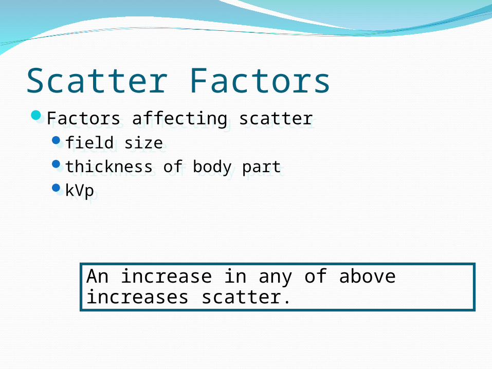
Scatter FactorsFactors affecting scatter
field sizethickness of body partkVp
Factors affecting scatterfield sizethickness of body partkVp
An increase in any of above increases scatter.

Scatter & Field SizeReducing field size causes significant
reduction in scatter radiation
IITube
X-RayTube
IITube
X-RayTube
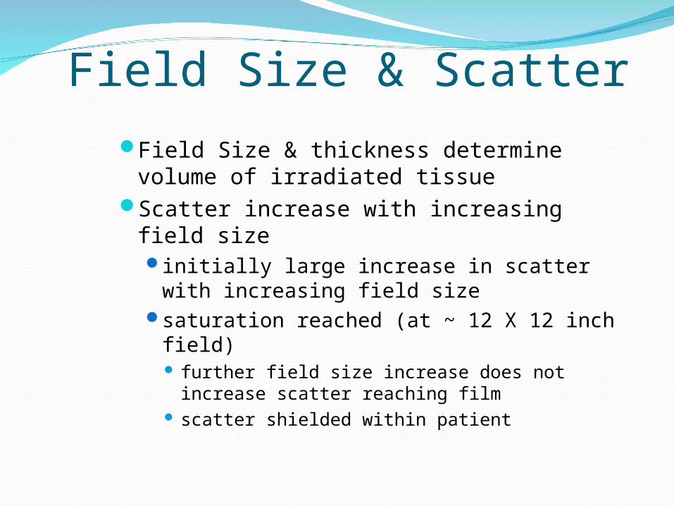
Field Size & ScatterField Size & thickness determine volume
of irradiated tissueScatter increase with increasing field size
initially large increase in scatter with increasing field size
saturation reached (at ~ 12 X 12 inch field) further field size increase does not increase
scatter reaching film scatter shielded within patient
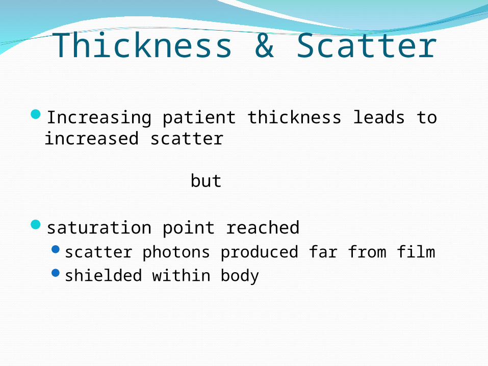
Thickness & Scatter
Increasing patient thickness leads to increased scatter
but
saturation point reachedscatter photons produced far from filmshielded within body

kVp & Scatter
kVp has less effect on scatter than thanfield sizethickness
Increasing kVp increases scattermore photons scatter in forward direction
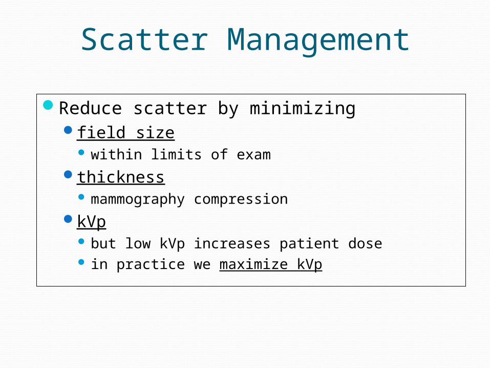
Scatter Management
Reduce scatter by minimizingfield size
within limits of examthickness
mammography compressionkVp
but low kVp increases patient dose in practice we maximize kVp

Scatter Control Techniques:Grid
directional filter for photonsIncreases patient dose
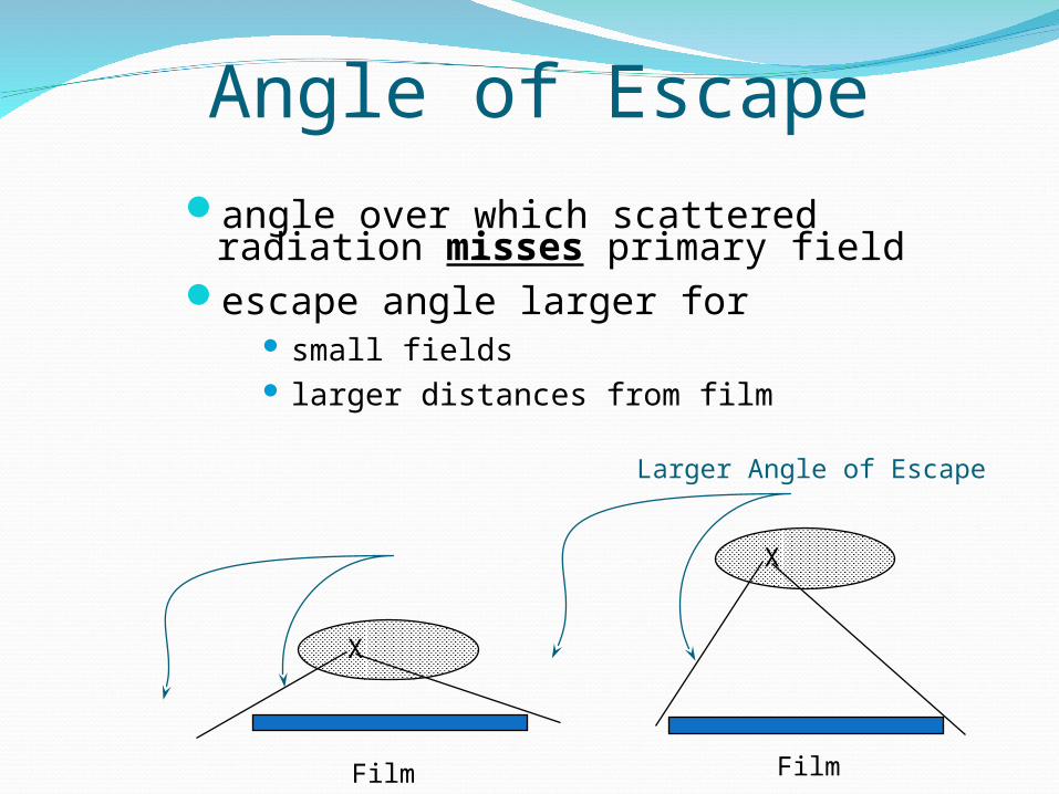
Angle of Escapeangle over which scattered radiation
misses primary fieldescape angle larger for
small fields larger distances from film
X
Film
X
Film
Larger Angle of Escape
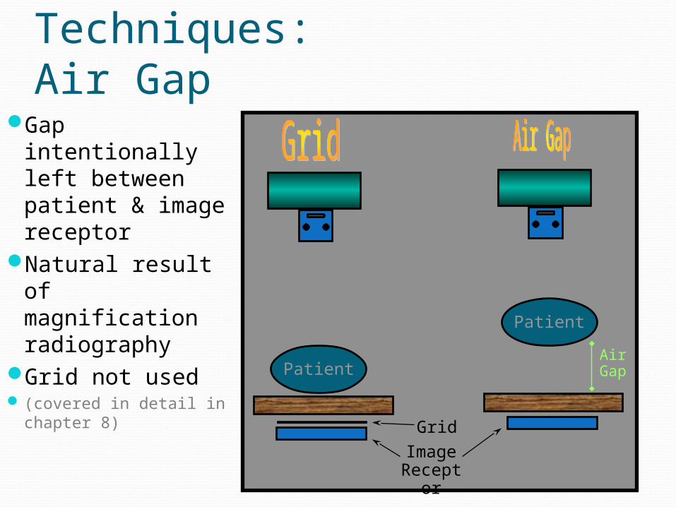
Scatter Control Techniques:Air Gap
Gap intentionally left between patient & image receptor
Natural result of magnification radiography
Grid not used (covered in detail in
chapter 8)
Patient
Patient
Grid
ImageReceptor
AirGap