residual stresses in cold-drawn rods: effect of a novel
TRANSCRIPT
RESIDUAL STRESSES IN COLD-DRAWN RODS: EFFECT OF A NOVEL POST-DRAWING TREATMENT
J. Ruiz-Hervias1, M. Hofmann2, J. Rebelo-Kornmeier2, V. Luzin3, and M. Elices1
1Dpto. Ciencia Materiales, Universidad Politécnica de Madrid, E-28040 Madrid, Spain 2FRM-II, TU München, Lichtenbergstr. 1, D-85747 Garching, Germany
3Bragg Institute, ANSTO, MENAI NSW 2234, Australia
ABSTRACT
Residual strains were measured in ferritic and pearlitic steel rods along the radial, axial and hoop directions. Samples were first subjected to one drawing pass with 20% section reduction and then to a second pass with only 1% section reduction (�skin-pass� treatment). After the first pass, the
calculated residual stresses are tensile at the rod surface and compressive in the interior. Stress balance is approximately fulfilled in the ferritic steel rods but this is not the case for the pearlitic ones, because stresses in the cementite phase could not be accounted for. The second drawing pass is very effective in reducing the residual stresses in the ferritic steel rods along the three principal directions. In the pearlitic steel rods, the residual stress state after the �skin-pass� treatment is quasi-uniaxial, with axial compressive residual stresses (around -350 MPa) in the ferrite phase.
INTRODUCTION
Wire drawing is a manufacturing process employed to improve mechanical properties by cold-working. The process consists of reducing the wire section by successive passes through a set of conical dies. This process is widely employed in industry for producing high tensile strength pearlitic steel wires that find widespread applications as structural reinforcements, such as prestressed concrete, mining and fishing cables and tire reinforcements [1,2]. Inhomogeneous plastic deformations associated with the fabrication process involve the development of residual stress and texture gradients across the section of the wire. The residual stress pattern developed for deep drawing consists of tensile stresses at the wire surface and compressive ones in the interior [3-7].
It is well known that residual stresses may influence both the mechanical behaviour of the wires and their durability. In cold-drawn eutectoid steel wires, the presence of residual stresses decrease the elastic limit and increases the stress relaxation losses [8,9]. In addition, time to rupture in stress corrosion tests is clearly reduced with tensile residual stresses at the wire surface [10,11]. Consequently, it is important to control the residual stress profile resulting from cold-drawing in order to optimize wire performance.
Wire manufacturers are aware of the problem and try to alleviate residual stresses by means of in-line post-drawing thermomechanical treatments. These treatments involve stretching the wire to a certain deformation at a moderate temperature. Other alternatives have been proposed, for example to subject the wires to a final drawing step with a very small section reduction (termed
747Copyright ©JCPDS-International Centre for Diffraction Data 2009 ISSN 1097-0002Advances in X-ray Analysis, Volume 52

This document was presented at the Denver X-ray Conference (DXC) on Applications of X-ray Analysis. Sponsored by the International Centre for Diffraction Data (ICDD). This document is provided by ICDD in cooperation with the authors and presenters of the DXC for the express purpose of educating the scientific community. All copyrights for the document are retained by ICDD. Usage is restricted for the purposes of education and scientific research. DXC Website – www.dxcicdd.com
ICDD Website - www.icdd.com
Advances in X-ray Analysis, Volume 52
�skin pass�). However, its effectiveness in terms of residual stress reduction has not been
assessed yet. In this work, samples of single phase (ferritic) and two-phase (pearlitic) steel rods were studied. Both were subjected to one drawing pass under precisely controlled conditions and some samples were given a second drawing pass with only a 1% section reduction (�skin pass�). Through-thickness residual strain profiles were measured by neutron diffraction in the ferrite phase along the three principal directions of the rods, namely radial, hoop and axial. Measurements were performed in the strain scanner StressSpec (FRM-II, Garching, Germany). The reference lattice spacing was measured in �comb-like� specimens fabricated by EDM.
EXPERIMENTAL
Material
Straight rods (16 mm diameter and 6 m length) of both ferritic and pearlitic steel (eutectoid steel) were specially produced for this research by Saarstahl AG (Völklingen, Germany). The aim was
to avoid residual stresses associated with coiling and at the same time to have a large cross section that would allow the measurement of the residual stress profile along the diameter. The rods were produced by hot rolling and aged to reduce residual stresses to a minimum. The chemical composition of both steels is given in Table 1.
Table 1. Chemical composition of ferritic and pearlitic steel rods (in weight percentage).
C (%) Si (%) Mn (%) P (%) S (%) Al (%)
Ferritic 0.04 0.10 0.20-0.45 0.035 0.035 0.02-0.06
Pearlitic 0.78 0.15-0.35 0.60-0.90 <0.025 <0.025 0.02-0.06
Samples were first cold-drawn in one pass (in precisely controlled conditions) to a final diameter of 14.3 mm (20% reduction in section) and then to a second pass with only 1% section reduction (�skin-pass� treatment). Die geometry was precisely measured. Details are given elsewhere [12]. The rods were kept straight during the whole process in order to avoid any change in the residual stress pattern generated by drawing.
Neutron diffraction measurements
The neutron diffraction experiments presented in this paper were performed on the Stress-Spec Diffractometer, at the FRMII reactor (Garching, Germany). Stress-Spec is located at the thermal beam port SR3 of FRM II and can easily be configured either for texture or stress analysis. The setup employed in the measurements on ferrite consists of a bent silicon monochromator Si(400) at a take-off angle of 82º, which corresponds to a wavelength of approximately 1.67 Angstrom. Another setup was employed to try and measure cementite: a Ge(311) monochromator at a take-off angle of 82º, which corresponds to a wavelength of approximately 2.1 Angstrom. The
748Copyright ©JCPDS-International Centre for Diffraction Data 2009 ISSN 1097-0002Advances in X-ray Analysis, Volume 52
monochromatic beam is diffracted by the specimen and detected by a position sensitive detector with an area of 20x20 cm2.
Strain scanning was carried out in the ferritic rods (single phase). It was attempted to measure residual strain in both phases of the pearlitic rods, namely ferrite and cementite. Cementite peaks were measured in the initial rods before cold-drawing. However, they virtually disappeared in cold-drawn rods. This is attributed to peak broadening associated to plastic deformation. Consequently, only measurements in the ferrite phase of both steel rods, namely ferritic and pearlitic, are reported. Ferrite strains were measured using the (211) diffraction line with ë = 1.6714 Å. This combination produces a Bragg peak around 2è = 91º, very close to the optimum (90º). The (211) peak was chosen because it is a good representative of the macroscopic behaviour in steels. Samples with a length to diameter ratio of 12 to 1 were cut from the rods. Measurements were performed in the central cross-section of the samples where the residual stresses generated by cold-drawing were not affected by the cutting process [12]. Ferrite lattice spacing was collected in the axial, radial and hoop directions of the samples, by measuring one point every mm. The strain scanning was carried out along the rod diameter. The slits connected to the diffractometer defined different gauge volumes for each component (with the aim of achieving the same spatial resolution). A nominal gauge volume of 2 x 2 x 2 mm3 was used in the axial measurements. For radial and hoop measurements, the beam could be enlarged vertically without loss in spatial resolution (due to the symmetry of the sample). So, in this case the slit dimensions were 2 x 10 mm2 (incident) and 2 mm (receiving).
The unstressed lattice spacing, d0, was computed from the initial rods (before cold-drawing). To this end, several cuts were carried out by electro-discharge machining in samples of the ferritic and pearlitic rods. The cuts left several isolated parallelepipeds (4x4x15 mm3) where d0 was measured in the radial/hoop orientation (gauge volume 2x10x2 mm3). The final d0 employed in the calculations for each steel was an average of the results corresponding to the different parallelepipeds in each sample.
EXPERIMENTAL RESULTS
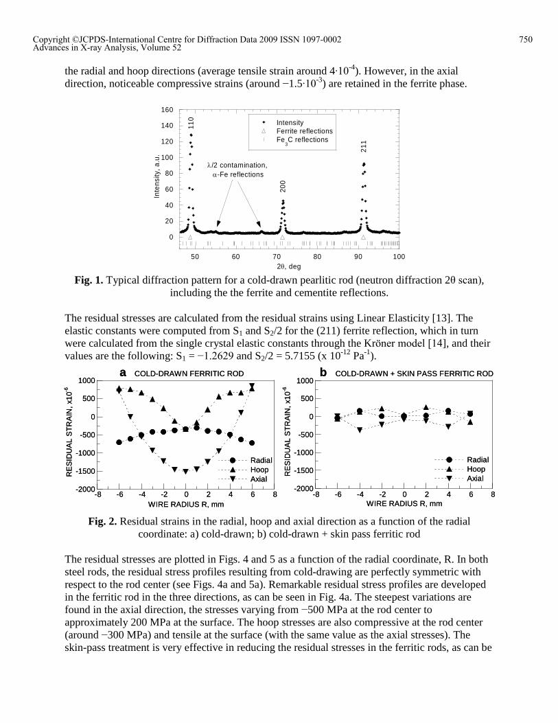
The experimental data are very good, with narrow diffraction peaks and very low background. As an illustration, a typical diffraction pattern for the cold-drawn pearlitic steel rod (neutron diffraction 2è scan) is shown in Fig. 1. There are some small peaks between the (200) and (110) ferrite reflections which do not correspond to cementite reflections, they are ë/2 contamination
ferrite reflections. As can be seen, cementite reflections are hidden in the background.
In all the figures the error bars for the strains and stresses are smaller than the symbols employed in the plots (typical error in stress is less than 10 MPa). The residual strains originated by cold-drawing in the ferritic rod (Fig 2a) are significantly reduced by the the skin pass treatment (Fig. 2b). The strain profiles corresponding to the three directions become flatter and closer to zero, the effect being more noticeable in the axial and hoop directions. For example, the axial strain at the rod center changes from −1.5∙10
-3 in the cold-drawn sample (Fig. 2a) to −10-4 in the sample subjected to the skin pass treatment (Fig. 2b).
In the pearlitic rod, the residual strains in the ferrite phase are larger than in the ferritic rod (compare Fig. 2a with Fig. 3a). The skin-pass treatment successfully reduces the residual strain in
749Copyright ©JCPDS-International Centre for Diffraction Data 2009 ISSN 1097-0002Advances in X-ray Analysis, Volume 52
the radial and hoop directions (average tensile strain around 4∙10-4). However, in the axial
direction, noticeable compressive strains (around −1.5∙10-3) are retained in the ferrite phase.
0
20
40
60
80
100
120
140
160
50 60 70 80 90 100
IntensityFerrite reflectionsFe
3C reflections
Inte
nsity
, a.u
.
2 deg
211
200
110
/2 contamination, -Fe reflections
Fig. 1. Typical diffraction pattern for a cold-drawn pearlitic rod (neutron diffraction 2è scan),
including the the ferrite and cementite reflections.
The residual stresses are calculated from the residual strains using Linear Elasticity [13]. The elastic constants were computed from S1 and S2/2 for the (211) ferrite reflection, which in turn were calculated from the single crystal elastic constants through the Kröner model [14], and their values are the following: S1 = −1.2629 and S2/2 = 5.7155 (x 10-12 Pa-1).
-2000
-1500
-1000
-500
0
500
1000
-8 -6 -4 -2 0 2 4 6 8
RadialHoopAxial
RE
SID
UA
L S
TR
AIN
, x1
0-6
WIRE RADIUS R, mm
a COLD-DRAWN FERRITIC ROD
-2000
-1500
-1000
-500
0
500
1000
-8 -6 -4 -2 0 2 4 6 8
RadialHoopAxial
RE
SID
UA
L S
TR
AIN
, x1
0-6
WIRE RADIUS R, mm
b COLD-DRAWN + SKIN PASS FERRITIC ROD
-2000
-1500
-1000
-500
0
500
1000
-8 -6 -4 -2 0 2 4 6 8
RadialHoopAxial
RE
SID
UA
L S
TR
AIN
, x1
0-6
WIRE RADIUS R, mm
a COLD-DRAWN FERRITIC ROD
-2000
-1500
-1000
-500
0
500
1000
-8 -6 -4 -2 0 2 4 6 8
RadialHoopAxial
RE
SID
UA
L S
TR
AIN
, x1
0-6
WIRE RADIUS R, mm
b COLD-DRAWN + SKIN PASS FERRITIC ROD
Fig. 2. Residual strains in the radial, hoop and axial direction as a function of the radial
coordinate: a) cold-drawn; b) cold-drawn + skin pass ferritic rod
The residual stresses are plotted in Figs. 4 and 5 as a function of the radial coordinate, R. In both steel rods, the residual stress profiles resulting from cold-drawing are perfectly symmetric with respect to the rod center (see Figs. 4a and 5a). Remarkable residual stress profiles are developed in the ferritic rod in the three directions, as can be seen in Fig. 4a. The steepest variations are found in the axial direction, the stresses varying from −500 MPa at the rod center to approximately 200 MPa at the surface. The hoop stresses are also compressive at the rod center (around −300 MPa) and tensile at the surface (with the same value as the axial stresses). The skin-pass treatment is very effective in reducing the residual stresses in the ferritic rods, as can be
750Copyright ©JCPDS-International Centre for Diffraction Data 2009 ISSN 1097-0002Advances in X-ray Analysis, Volume 52
seen in Fig. 4b. The axial residual stress profile still shows some symmetry with respect to the rod center, with negligible stresses both at the rod surface and at the center. A minimum value of -100 MPa is found close to the rod surface (R = ±4 mm). On the other hand, the radial and hoop
stresses are almost negligible at all points along the rod diameter (maximum around +50 MPa in the hoop direction).
-4000
-3000
-2000
-1000
0
1000
2000
-8 -6 -4 -2 0 2 4 6 8
RadialHoopAxial
RE
SID
UA
L S
TR
AIN
, x1
0-6
WIRE RADIUS R, mm
a COLD-DRAWN PEARLITIC ROD
-4000
-3000
-2000
-1000
0
1000
2000
-8 -6 -4 -2 0 2 4 6 8
RadialHoopAxialR
ES
IDU
AL
ST
RA
IN,
x10-6
WIRE RADIUS R, mm
b COLD-DRAWN + SKIN PASS PEARLITIC ROD
-4000
-3000
-2000
-1000
0
1000
2000
-8 -6 -4 -2 0 2 4 6 8
RadialHoopAxial
RE
SID
UA
L S
TR
AIN
, x1
0-6
WIRE RADIUS R, mm
a COLD-DRAWN PEARLITIC ROD
-4000
-3000
-2000
-1000
0
1000
2000
-8 -6 -4 -2 0 2 4 6 8
RadialHoopAxialR
ES
IDU
AL
ST
RA
IN,
x10-6
WIRE RADIUS R, mm
b COLD-DRAWN + SKIN PASS PEARLITIC ROD
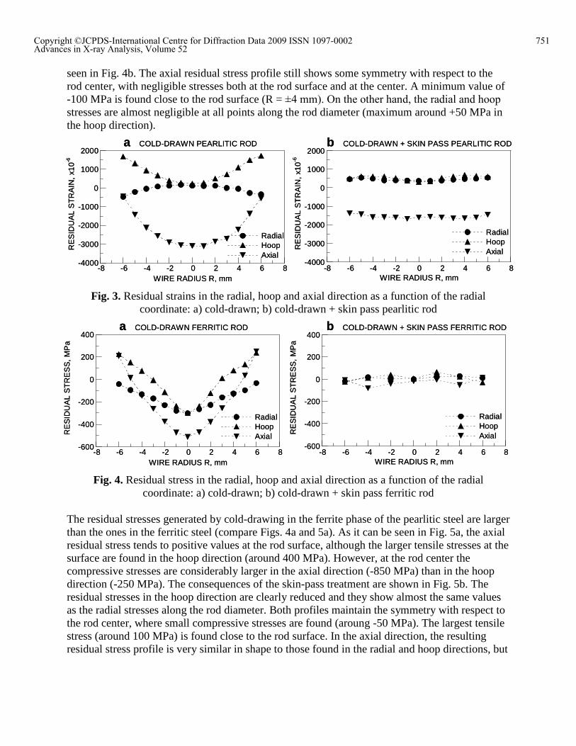
Fig. 3. Residual strains in the radial, hoop and axial direction as a function of the radial
coordinate: a) cold-drawn; b) cold-drawn + skin pass pearlitic rod
-600
-400
-200
0
200
400
-8 -6 -4 -2 0 2 4 6 8
RadialHoopAxialR
ES
IDU
AL
ST
RE
SS
, M
Pa
WIRE RADIUS R, mm
a COLD-DRAWN FERRITIC ROD
-600
-400
-200
0
200
400
-8 -6 -4 -2 0 2 4 6 8
RadialHoopAxialR
ES
IDU
AL
ST
RE
SS
, M
Pa
WIRE RADIUS R, mm
b COLD-DRAWN + SKIN PASS FERRITIC ROD
-600
-400
-200
0
200
400
-8 -6 -4 -2 0 2 4 6 8
RadialHoopAxialR
ES
IDU
AL
ST
RE
SS
, M
Pa
WIRE RADIUS R, mm
a COLD-DRAWN FERRITIC ROD
-600
-400
-200
0
200
400
-8 -6 -4 -2 0 2 4 6 8
RadialHoopAxialR
ES
IDU
AL
ST
RE
SS
, M
Pa
WIRE RADIUS R, mm
b COLD-DRAWN + SKIN PASS FERRITIC ROD
Fig. 4. Residual stress in the radial, hoop and axial direction as a function of the radial
coordinate: a) cold-drawn; b) cold-drawn + skin pass ferritic rod
The residual stresses generated by cold-drawing in the ferrite phase of the pearlitic steel are larger than the ones in the ferritic steel (compare Figs. 4a and 5a). As it can be seen in Fig. 5a, the axial residual stress tends to positive values at the rod surface, although the larger tensile stresses at the surface are found in the hoop direction (around 400 MPa). However, at the rod center the compressive stresses are considerably larger in the axial direction (-850 MPa) than in the hoop direction (-250 MPa). The consequences of the skin-pass treatment are shown in Fig. 5b. The residual stresses in the hoop direction are clearly reduced and they show almost the same values as the radial stresses along the rod diameter. Both profiles maintain the symmetry with respect to the rod center, where small compressive stresses are found (aroung -50 MPa). The largest tensile stress (around 100 MPa) is found close to the rod surface. In the axial direction, the resulting residual stress profile is very similar in shape to those found in the radial and hoop directions, but
751Copyright ©JCPDS-International Centre for Diffraction Data 2009 ISSN 1097-0002Advances in X-ray Analysis, Volume 52
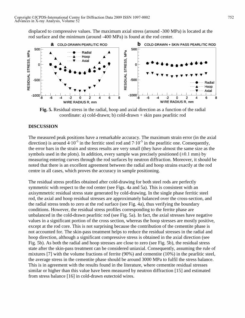
displaced to compressive values. The maximum axial stress (around -300 MPa) is located at the rod surface and the minimum (around -400 MPa) is found at the rod center.
-1000
-500
0
500
-8 -6 -4 -2 0 2 4 6 8
RadialHoopAxialR
ES
IDU
AL
ST
RE
SS
, M
Pa
WIRE RADIUS R, mm
b COLD-DRAWN + SKIN PASS PEARLITIC ROD
-1000
-500
0
500
-8 -6 -4 -2 0 2 4 6 8
RadialHoopAxial
RE
SID
UA
L S
TR
ES
S, M
Pa
WIRE RADIUS R, mm
a COLD-DRAWN PEARLITIC ROD
-1000
-500
0
500
-8 -6 -4 -2 0 2 4 6 8
RadialHoopAxialR
ES
IDU
AL
ST
RE
SS
, M
Pa
WIRE RADIUS R, mm
b COLD-DRAWN + SKIN PASS PEARLITIC ROD
-1000
-500
0
500
-8 -6 -4 -2 0 2 4 6 8
RadialHoopAxial
RE
SID
UA
L S
TR
ES
S, M
Pa
WIRE RADIUS R, mm
a COLD-DRAWN PEARLITIC ROD
Fig. 5. Residual stress in the radial, hoop and axial direction as a function of the radial
coordinate: a) cold-drawn; b) cold-drawn + skin pass pearlitic rod
DISCUSSION
The measured peak positions have a remarkable accuracy. The maximum strain error (in the axial direction) is around 4∙10
-5 in the ferritic steel rod and 7∙10-5 in the pearlitic one. Consequently,
the error bars in the strain and stress results are very small (they have almost the same size as the symbols used in the plots). In addition, every sample was precisely positioned (±0.1 mm) by
measuring entering curves through the rod surfaces by neutron diffraction. Moreover, it should be noted that there is an excellent agreement between the radial and hoop strains exactly at the rod centre in all cases, which proves the accuracy in sample positioning.
The residual stress profiles obtained after cold-drawing for both steel rods are perfectly symmetric with respect to the rod center (see Figs. 4a and 5a). This is consistent with an axisymmetric residual stress state generated by cold-drawing. In the single phase ferritic steel rod, the axial and hoop residual stresses are approximately balanced over the cross-section, and the radial stress tends to zero at the rod surface (see Fig. 4a), thus verifying the boundary conditions. However, the residual stress profiles corresponding to the ferrite phase are unbalanced in the cold-drawn pearlitic rod (see Fig. 5a). In fact, the axial stresses have negative values in a significant portion of the cross section, whereas the hoop stresses are mostly positive, except at the rod core. This is not surprising because the contribution of the cementite phase is not accounted for. The skin-pass treatment helps to reduce the residual stresses in the radial and hoop direction, although a significant compressive stress is obtained in the axial direction (see Fig. 5b). As both the radial and hoop stresses are close to zero (see Fig. 5b), the residual stress state after the skin-pass treatment can be considered uniaxial. Consequently, assuming the rule of mixtures [7] with the volume fractions of ferrite (90%) and cementite (10%) in the pearlitic steel, the average stress in the cementite phase should be around 3000 MPa to fulfil the stress balance. This is in agreement with the results found in the literature, where cementite residual stresses similar or higher than this value have been measured by neutron diffraction [15] and estimated from stress balance [16] in cold-drawn eutectoid wires.
752Copyright ©JCPDS-International Centre for Diffraction Data 2009 ISSN 1097-0002Advances in X-ray Analysis, Volume 52
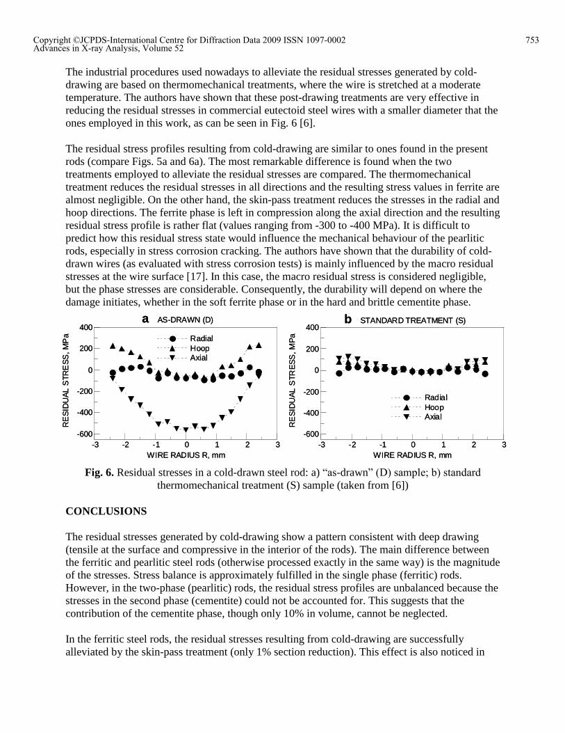
The industrial procedures used nowadays to alleviate the residual stresses generated by cold-drawing are based on thermomechanical treatments, where the wire is stretched at a moderate temperature. The authors have shown that these post-drawing treatments are very effective in reducing the residual stresses in commercial eutectoid steel wires with a smaller diameter that the ones employed in this work, as can be seen in Fig. 6 [6].
The residual stress profiles resulting from cold-drawing are similar to ones found in the present rods (compare Figs. 5a and 6a). The most remarkable difference is found when the two treatments employed to alleviate the residual stresses are compared. The thermomechanical treatment reduces the residual stresses in all directions and the resulting stress values in ferrite are almost negligible. On the other hand, the skin-pass treatment reduces the stresses in the radial and hoop directions. The ferrite phase is left in compression along the axial direction and the resulting residual stress profile is rather flat (values ranging from -300 to -400 MPa). It is difficult to predict how this residual stress state would influence the mechanical behaviour of the pearlitic rods, especially in stress corrosion cracking. The authors have shown that the durability of cold-drawn wires (as evaluated with stress corrosion tests) is mainly influenced by the macro residual stresses at the wire surface [17]. In this case, the macro residual stress is considered negligible, but the phase stresses are considerable. Consequently, the durability will depend on where the damage initiates, whether in the soft ferrite phase or in the hard and brittle cementite phase.
-600
-400
-200
0
200
400
-3 -2 -1 0 1 2 3
RadialHoopAxial
RE
SID
UA
L S
TRE
SS
, MP
a
WIRE RADIUS R, mm
b STANDARD TREATMENT (S)
-600
-400
-200
0
200
400
-3 -2 -1 0 1 2 3
RadialHoopAxial
RE
SID
UA
L S
TRE
SS
, MP
a
WIRE RADIUS R, mm
a AS-DRAWN (D)
-600
-400
-200
0
200
400
-3 -2 -1 0 1 2 3
RadialHoopAxial
RE
SID
UA
L S
TRE
SS
, MP
a
WIRE RADIUS R, mm
b STANDARD TREATMENT (S)
-600
-400
-200
0
200
400
-3 -2 -1 0 1 2 3
RadialHoopAxial
RE
SID
UA
L S
TRE
SS
, MP
a
WIRE RADIUS R, mm
a AS-DRAWN (D)
Fig. 6. Residual stresses in a cold-drawn steel rod: a) �as-drawn� (D) sample; b) standard
thermomechanical treatment (S) sample (taken from [6])
CONCLUSIONS
The residual stresses generated by cold-drawing show a pattern consistent with deep drawing (tensile at the surface and compressive in the interior of the rods). The main difference between the ferritic and pearlitic steel rods (otherwise processed exactly in the same way) is the magnitude of the stresses. Stress balance is approximately fulfilled in the single phase (ferritic) rods. However, in the two-phase (pearlitic) rods, the residual stress profiles are unbalanced because the stresses in the second phase (cementite) could not be accounted for. This suggests that the contribution of the cementite phase, though only 10% in volume, cannot be neglected.
In the ferritic steel rods, the residual stresses resulting from cold-drawing are successfully alleviated by the skin-pass treatment (only 1% section reduction). This effect is also noticed in
753Copyright ©JCPDS-International Centre for Diffraction Data 2009 ISSN 1097-0002Advances in X-ray Analysis, Volume 52
the ferrite phase of pearlitic steel rods, where the stresses in the radial and hoop directions are negligible. However, the residual stress in the axial direction is compressive with a rather flat profile (values ranging from -300 to -400 MPa along the rod diameter). Consequently, the estimated residual stress in the cementite phase must be around 3000 MPa in order to fulfil the stress balance in this quasi-uniaxial residual stress state.
The thermomechanical treatments currently employed by the manufacturers produce negligible residual stresses in the ferrite phase of cold-drawn eutectoid steel wires. On the other hand, the axial residual stresses resulting from the skin-pass treatment cannot be neglected. It is hypothesized that in this case the durability in aggressive environments will depend on where the damage initiates, whether in the soft ferrite phase (subjected to compressive axial stress) or in the hard and brittle cementite phase (subjected to tensile axial stress).
ACKNOWLEDGEMENTS
The Spanish Ministry of Education (�Ministerio de Educación, Cultura y Deporte�) is gratefully
acknowledged for supporting this research through the projects MAT2002-04343 and ENE2005-06478/CON. The authors are indebted to the EU for funding support to perform the neutron scattering measurements through the Neutron and Muon Integrated Infrastructure Initiative (NMI3).The authors are also very grateful to Dr. J.M. Atienza for helpful discussions. The present work was conducted within the framework provided by the projects DUMEINPA, sponsored by the Comunidad de Madrid, Spain, and SEDUREC, integrated in the Spanish national research program CONSOLIDER-INGENIO 2010.
REFERENCES
[1] A.B. Dove, Wire J. Int. November (1983) 58-65 [2] M. Elices, J. Mater. Sci. 39 (2004) 3889-3899. [3] P.J. Webster, G. Mills, Physica B 241 (1997) 1270-1273. [4] P.J. Webster, G. Mills, X.D. Wang, W.P. Kang, T.M. Holden, G.F. Modlen, in: ICRS-4: Proceedings of the 4th International Conference on Residual Stresses, S.E.M., 1994, pp. 24-31. [5] M.L. Martinez-Perez, F.J. Mompean, J. Ruiz-Hervias, C.R. Borlado, J.M. Atienza, M. Garcia-Hernandez, M. Elices, J. Gil-Sevillano, R.L. Peng, T. Buslaps, Acta Mater. 52 (2004) 5303-5313 [6] J. Ruiz-Hervias, V. Luzin, H. Prask, T. Gnaeupel-Herold, M. Elices, Mat. Sci. Eng. A-Struct. 435-436 (2006) 725-735. [7] J. Ruiz-Hervias, J.M. Atienza, M. Elices, E.C. Oliver, Mat. Sci. Eng. A-Struct. 480, (2008), 439-448. [8] J.M. Atienza, M. Elices, Mater. Struct. 36 (2003) 548-552. [9] J.M. Atienza, M. Elices, Mater. Struct. 37 (2004) 301-304. [10] M. Elices, G. Maeder, V. Sanchez-Galvez, Brit. Corros. J. 18 (1983) 80-81. [11] M. Elices, J. Ruiz, J.M. Atienza, Mater. Struct. 37 (2004) 305-310. [12] J. Ruiz, J.M. Atienza, M. Elices, J. Mater. Eng. Perform. 12 (2003) 480-489. [13] I.C. Noyan, J.B. Cohen, Residual Stress: Measurement by Diffraction and Interpretation, Springer-Verlag New York Inc., Berlin, 1987. [14] T. Gnaupel-Herold, P.C. Brand, H.J. Prask, J. Appl. Crystallogr. 31 (1998) 929-935. [15] K. Van Acker, J. Root, P. Van Houtte, E. Aernoudt, Acta Mater. 44 (1996) 4039-49 [16] Y. Tomota, P. Lukas, D. Neov, S. Harjo, YR Abe, Acta Mater. 51 (2003) 805-817 [17] M. Elices, L. Caballero, A. Valiente, J. Ruiz, A. Martin, Corrosion 64 (2008) 164-174
754Copyright ©JCPDS-International Centre for Diffraction Data 2009 ISSN 1097-0002Advances in X-ray Analysis, Volume 52