resoluçoes hvac lg
DESCRIPTION
resolução defeitos vrvTRANSCRIPT

Error! Style not defined. Error!
18 TROUBLESHOOTING
CONTENTS
18 TROUBLESHOOTING ______________________________________________________ 1
18.1 Initial Troubleshooting ______________________________________________________ 2 18.1.1 This Is Not Abnormal_______________________________________________________ 2 18.1.2 Not Cooling or Heating Well _________________________________________________ 2 18.1.3 Not Operate _____________________________________________________________ 2
18.2 Alarm Codes______________________________________________________________ 3
18.3 Troubleshooting in Check mode_______________________________________________ 4 18.3.1 Contents of Check Mode 1 __________________________________________________ 5 18.3.2 Contents of Check Mode 2 __________________________________________________ 8
18.4 Troubleshooting by 7-segment display ________________________________________ 10 18.4.1 Simple checking by 7-Segment Display _______________________________________ 10 18.4.2 Checking Method by 7-Segment Display ______________________________________ 10 18.4.3 Running Current of Compressor _____________________________________________ 15
18.5 Protection control code on 7-segment display ___________________________________ 16
18.6 Self checking of PCB's using Remote Control Switch _____________________________ 19
18.7 Self Checking of Remote Control Switch _______________________________________ 21
Error! Error! Style not defined.
18.1 INITIAL TROUBLESHOOTING
18.1.1 THIS IS NOT ABNORMAL � Smells from Indoor Unit
Smell adheres on indoor unit after a long period of time. Clean the air filter and panels or allow a good ventilation.
� Sound from Deforming Parts During system starting or stopping, an abrading sound might be heard. However, this is due to thermal deformation of plastic parts. It is not abnormal.
� Steam from Outdoor Heat Exchanger During defrosting operation, ice on the outdoor heat exchanger is melted, resulting in making steam.
� Dew on Air Panel When the cooling operation continues for a long period of time under high humidity conditions (higher than 27°C DB/80% R.H), dew can form on the air panel.
� Refrigerant Flow Sound While the system is being started or stopped, sound from the refrigerant flow may be heard.
18.1.2 NOT COOLING OR HEATING WELL � Check for obstruction of air flow of the outside or inside
units.
� Check if too much heat source exists in the room.
� Check if the air filter is clogged with dust.
� Check to see if the doors or windows are opened or not.
� Check if the temperature condition is not within the operation range.
18.1.3 NOT OPERATE � Check for electrical wiring.
� Check for dip switch setting.
� Check whether the “SET TEMP” is set at the correct temperature.
� In the case that “RUN” lamp on remote control switch is flickering every 2 seconds, check for connection of remote control line.
� In the case that “RUN” lamp flashes 5 times (5 seconds) with unit number and alarm code displayed, refer to the next item “18.2 Troubleshooting by Alarm Code” and the “Service Manual”.
� In the case that no alarm code is indicated and normal operation is not available, refer to the “Service Manual” because abnormality of some device is suspected.

Error! Style not defined. Error!
18.2 ALARM CODES
If RUN lamp flashes 5 times (5 seconds) with unit number and alarm code displayed, note the alarm code (see table below) and ask your contractor for service.
Unit Number Alarm Code Model Code
If RUN lamp flashes for 2 seconds, there is a failure in transmission between Indoor Unit and Remote Control Switch. Possible causes are:
� Remote Cable broken
� Contact Failure in Remote Control Cable
� IC or Microcomputer defective
In any case, ask your contractor for service
Refrigerant Cycle Number Number of connected Units
Code No. Category Content of Abnormality Leading Cause
01 Indoor Unit Tripping of Protection Device Failure of Fan Motor, Drain Discharge, PCB, Relay. 02 Outdoor Unit Tripping of Protection Device Activation of PSH
03 Transmission Abnormality between Indoor (or Outdoor) and Outdoor (or Indoor)
Incorrect Wiring. Failure of PCB. Tripping of Fuse. Power Supply OFF
04 Inverter Abnormality between Inverter and Control PCB Failure in Transmission between PCBs 05 Transmission Abnormality of Power Source Wiring Reverse Phase Incorrect Wiring.
06 Voltage Drop Voltage Drop by Excessively Low or High Voltage to Outdoor Unit
Voltage Drop of Power Supply. Incorrect Wiring or insufficient Capacity of Power Supply Wiring.
07 Decrease in Discharge Gas Superheat Excessive Refrigerant Charge. Expansion Valve Open Lock.
08 Cycle
Increase in Discharge Gas Temperature Insufficient Refrigerant. Ref. Leakage, Clogging or Expansion Valve Close Lock
09 Outdoor Unit Tripping of Protection Device Failure of Fan Motor. 11 Inlet Air Thermistor 12 Outlet Air Thermistor 13 Freeze Protection Thermistor 14 Gas Piping Thermistor
Failure of Thermistor, Sensor, Connection.
19
Sensor on Indoor Unit
Tripping of Protection Device for Fan Motor Failure of Fan Motor 21 High Pressure Sensor 22 Outdoor Air Thermistor 23 Discharge Gas Thermistor on Comp. 24 Evaporating Thermistor 29
Sensor on Outdoor Unit
Low Pressure Sensor
Failure of Thermistor, Sensor, Connection
30 Incorrect Wiring Connection Incorrect Wiring Connection between Outdoor Unit, CH Unit and Indoor Unit
31 Incorrect Setting of Outdoor and Indoor Unit Incorrect Setting of Capacity Code.
32 Abnormal Transmission of Other Indoor Unit Failure of Power Supply, PCB in other Indoor Unit. Failure of other Indoor Unit of the same Refrigerant Cycle
35 Incorrect Setting in Indoor Unit No. Existence of the same Indoor Unit No. in the same Refrigerant Cycle
38 Abnormality of Protective Circuit in Outdoor Unit Failure of Indoor Unit PCB. Incorrect wiring. Connection to PCB in Indoor Unit.
39
System
Abnormality of Running Current at Constant Compressor Overcurrent, Blown Fuse of Failure of Current Sensor.
43 Pressure Ratio Decrease Protection Activating Failure of Compressor, Inverter
44 Low Pressure Increase Protection Activating Overload to Indoor in Cooling. High Temperature of Outdoor Air In Heating Expansion Valve Open Lock
45 High Pressure Increase Protection Activating Overload Operation. Excessive Refrigerant. Clogging of Heat Exchanger
46 High Pressure Decrease Protection Activating Insufficient Refrigerant. 47
Pressure
Low Pressure Decrease Protection Activating Insufficient refrigerant . 51 Abnormality of Current Sensor for Inverter Failure of Sensor on Inverter PCB 52 Overcurrent Protection Activating Overload, Overcurrent, Locking to Compressor.
53 IPM Protection Activating Automatic Stoppage of IPM (Overcurrent, Low Voltage or Overheating).
54
Inverter
Increase in Inverter Fin Temperature Abnormal Inverter Fin Thermistor. Abnormal Outdoor Fan
56 Abnormality of Detection for Fan Motor Position Abnormal detection Circuit of Transmission 57 Fan Controller Protection Activating Abnormal Fan Speed 58
Outdoor Fan Abnormality of Fan Controller Overcurrent, Abnormal Fan Controller Fin
59 AC Chopper AC Chopper Circuit Protection Failure of FET, Power Supply, CT for Fan Motor
EE Inverter Compressor Protection 3 Time Occurrence of Alarm Giving Damage to Compressor within 6 hours
Error! Error! Style not defined.
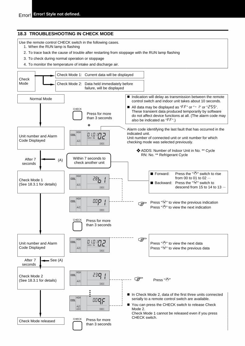
18.3 TROUBLESHOOTING IN CHECK MODE
Use the remote control CHECK switch in the following cases. 1. When the RUN lamp is flashing
2. To trace back the cause of trouble after restarting from stoppage with the RUN lamp flashing
3. To check during normal operation or stoppage
4. To monitor the temperature of intake and discharge air.
Check Mode 1: Current data will be displayed Check
Mode Check Mode 2: Data held immediately before failure, will be displayed
Normal Mode
CHECK
Press for more than 3 seconds
� Indication will delay as transmission between the remote control switch and indoor unit takes about 10 seconds.
� All data may be displayed as "FF" or "-1" or "". These transient data produced temporarily by software do not affect device functions at all. (The alarm code may also be indicated as "FF".)
❖
Unit number and Alarm Code Displayed
Within 7 seconds to check another unit
Alarm code identifying the last fault that has occurred in the indicated unit. Unit number of connected unit or unit number for which checking mode was selected previously.
❖ ADDS: Number of Indoor Unit in No. ** Cycle RN: No. ** Refrigerant Cycle
After 7 seconds
(A)
Check Mode 1 (See 18.3.1 for details)
■ Forward: Press the "" switch to rise from 00 to 01 to 02 ···
■ Backward: Press the "" switch to descend from 15 to 14 to 13 ···
� Press "" to view the previous indication Press "” to view the next indication
CHECK Press for more than 3 seconds
Unit number and Alarm Code Displayed
� Press "" to view the next data Press "" to view the previous data
After 7 seconds
See (A)
Check Mode 2 (See 18.3.1 for details)
� Press ""
Check Mode released
CHECK Press for more than 3 seconds
� In Check Mode 2, data of the first three units connected serially to a remote control switch are available.
� You can press the CHECK switch to release Check Mode 2. Check Mode 1 cannot be released even if you press CHECK switch.

Error! Style not defined. Error!
Although the wireless controller is used for wall type indoor unit with built-in receiver part, the alarm code can be checked by connecting PC-P1HE .
NOTE:
1. The unit is not operated by pressing operation switch.
2. The above function is available only when alarm occurs.
3. The PCB check by remote controller is not available.
4. The indication is the data when connecting PC-P1H, not the data before the alarm occurs.
18.3.1 CONTENTS OF CHECK MODE 1
The next indication is shown by pressing the part "" of "TEMP" switch. If the part "" of "TEMP" switch is pressed, the previous indication is shown.
Temperature indication
b1 22
1 Indoor Unit Temp. Setting (°C)
↓
b2 20
2 Indoor Unit Intake Air Temp. at Thermistor (°C)
↓
b3 55
3 Indoor Unit Discharge Air Temp. at Thermistor (°C)
↓
b4 20
4 Indoor Unit Heat Exchanger Liquid pipe Temp °C
↓
b5 25
5 Temperature at Remote Sensor (°C)
↓
b6 10
6 Outdoor Unit Ambient Temp. (°C)
↓
b7 25
7 Indoor Unit Heat Exchanger Gas Pipe Temp. (°C)
↓
b8 02
8 Outdoor Unit Evaporating Temp. during Heating (°C)
↓
b9 --
9 Control Information
↓
bA 41
10 Discharge Gas Temp. at the Top of Comp. Chamber (°C)
↓to next page
Normal
Abnormal
. . . Temperature displayed
– –
129
(Thermistor Open circuited or PCB defected)
(Temp. for Top of Comp.)
FF
or
(Thermistor Short circuited or PCB defected)
255
or
Indication of Category Code Indication of Temperature, etc
Connector for Check
Suction Grille
This indicates the internal information for the remote control switch. In case of SET-FREE, this indication shows the operating compressor quantity.
(Ex.) During several compressors operation, average temperature of two compressors is indicated
In case that temperature is higher than 126°C, "126"
127
or
(Temp. for Top of Comp.)
See "18.6 Self-Checking of PCB's using Remote Control Switch"
During transient periods such as starting time, etc., "" or "" may be indicated for a limited time.
This is indicated only when a remote sensor is connected. The indication of "--" is normally indicated. RPK series can not connect a remote sensor. Therefore, indication is "--".

Error! Error! Style not defined.
bb 23
11 Thermo Temp. of Remote Control Switch
↓ Indication on Micro-Computer Input /Output
C1 Z
12 Micro Computer Input/Output in Indoor Unit
↓
C2 -
13 Micro Computer Input/Output in Outdoor Unit
↓ ↓ ↓ ↓
Indication of Unit Stoppage cause
d1 01
14 Cause of Stoppage
↓ Abnormality Occurrence Counter
E1 01
15 Abnormality Occurrence Times
↓
E2 00
16 Instantaneous Power Failure Occurrence Times in Indor Unit
↓
E3 00
17 Transmission Error Occurrence Times between Remote Control Switch and Indoor Unit
↓
E4 00
18 Abnormality Occurrence Times on Inverter
↓ ↓ ↓ ↓ ↓
↓ Indication of Automatic Louver Condition
F1 00
19 Louver Sensor
↓to next page
00 Operation OFF, Power OFF 01 Thermo - OFF (Note 1) 02 Alarm (Note 2) 03 Freeze Protection, Overheating Protection 05 Instantaneous Power Failure at Outdoor Unit, Reset (Note 3) 06 Instantaneous Power Failure at Indoor Unit, Reset (Note 4)
07 Stoppage of Cooling Operation due to Low Outdoor Air Temperature, Stoppage of Heating Operation due to High Outdoor Air Temperature
08 Compressor Quantity Changeover, Stoppage (HP≥8) 10 Demand, Enforced Stoppage 11 Retry due to Pressure Ratio Decrease 12 Retry due to Low Pressure Increase 13 Retry due to High Pressure Increase 14 Retry due to Abnormal Current of Constant Compressor (HP≥8)
15 Retry due to Abnormal High Temperature of Discharge Gas, Excessive Low Suction Pressure
16 Retry due to Decrease of Discharge Gas Superheat 17 Retry due to Inverter Tripping 18 Retry due to Voltage Decrease 19 Expansion Valve Opening Change Protection 20 Operation Mode Changeover of Indoor Unit (Note 5)
NOTE: 1. Explanation of Terms
Thermo-ON: A condition than an Indoor Unit is requesting compressor to operate.
Thermo-OFF: A condition than an Indoor Unit is not requesting compressor to operate.
2. Even if stoppage is caused by "Alarm", "02" is not always indicated.
3. If transmission between the inverter printed circuit board and the control printed circuit board is not performed during 30 seconds, stoppage is d1-05 cause and the alarm code "04" may be indicated.
4. If transmission between the Indoor Unit and the Outdoor Unit is nor performed during 3 minutes, Indoor Units are stopped. In this case, stoppage is d1-06 cause and the alarm code "03" may be indicated.
5. In the FS(3/5) system "20" will be indicated at the difference mode between Indoor Units.
Countable up to 99. Over 99 times, "99" is always indicated.
NOTE: 1. If a transmitting error continues for 3 minutes, one is added to the
occurrence times. 2. The memorized data can be cancelled by the method indicated in
18.6 "Self-checking of PCBs using Remote Control Switch"
00 : Normal
FF : Abnormal
YH2
Y52H
Operation
Alarm Heating Thermo-ON
Coding Thermo-ON
Dark
Y20A
Y20B
Y211 Y52C1 Y52C2
Outdoor Fan
Symbols with a letter Y are relays of PCB
Dark
Y212
PCB Relay
Part Name
YH2 Relay for Drain pump (MD) and/or Dew Heater (EHW)
Y52H Relay for Electric Heater (CEH)
Y211
Y212 Relay for 4-Way Valve
Y52C1 Relay for Compressor
Y52C2
Y20A
Y20B Relay for Solenoid Valve

Error! Style not defined. Error!
Compressor Pressure/Frequency Indication
HI 18
20 Discharge Pressure (High) (x 0.1 MPa)
↓
H2 04
21 Suction Pressure (Low) (x 0.01 MPa)
↓
H3 44
22 Control Information
↓
H4 44
23 Operation Frequency (Hz)
↓ Indoor Unit Capacity Indication
J1 08
24 Indoor Unit Capacity
↓
J2 Fn
25 Outdoor Unit Code
↓
J3 01
26 Refrigerant Cycle Number
↓
J4 00
27 Refrigerant Cycle Number
↓ Expansion Opening Indication
L1 20
28 Indoor Unit Expansion Valve Opening (%)
↓
L2 gg
29 Outdoor Unit Expansion Valve MV1 Opening (%)
↓
L3 gg
30 Outdoor Unit Expansion Valve MV2 Opening (%)
↓
L4 00
31 Outdoor Unit Expansion Valve MVB Opening (%)
↓ Estimated Electric Current Indication
P1 25
32 Compressor Running Current (A)
↓ Returns to Temperature Indication Temperature Indication
This is an indication for internal information for the remote control switch. This does not have any specific meaning. The total frequency is indicated when several compressors are running
The capacity of the Indoor Unit is indicated as shown in the table below. Capacity Code of Indoor Unit
Indication Code Equivalent Capacity (HP) 06 0.8 08 1.0 10 1.3 13 1.5 14 1.8 16 2.0 18 2.3 20 2.5 22 2.8 26 3.0 32 4.0 40 5.0
"n" indicates total number of Indoor Units;
n= 1 ~ 9, A, b, C, d, E, F, U (10) (11) (12) (13) (14) (15) (16) J3: 01 ~ 16 (01: when shipment (DSW5), Decimal indication J4: 00 ~ 0F (00: when shipment (DSW5), Indication with 16 numbers
In case of models without Expansion Valve (MV2), the same figure is indicated
The total current is indicated when several compressors are running. In case of inverter compressor, the running current of primary side of inverter is indicated
FX series only

Error! Error! Style not defined.
18.3.2 CONTENTS OF CHECK MODE 2 The latest data of the first three indoor units only connected serially are indicated when more than three indoor units are connected to one remote control switch. By pressing the "" part of "TEMP" switch, the next display is indicated. If the part "" of "TEMP" switch is pressed, the previous display is indicated.
Temperature indication
91 23
1 Indoor Unit Intake Air Temp. at Thermistor (°C)
↓
92 50
2 Indoor Unit Discharge Air Temp. at Thermistor (°C)
↓
93 25
3 Indoor Unit Exchanger Liquid Pipe Temp. (Freeze protection) (°C)
↓
94 12
4 Outdoor Aire Temperature (°C)
↓
95 25
5 Indoor Heat Exchanger gas Pipe Temp. (°C)
↓
96 03
6 Evaporating Temp. at Heating (°C)
↓
97 --
7 Control information
↓
98 45
8 Discharge Gas Temp. at the Top of Comp. Chamber (°C)
↓ to next page
This is an indication for internal information for the remote control switch. This does not have any specific meaning. The average temperature is indicated when two compressors are running
Normal
Abnormal
. . . Temperature displayed
– –
129
(Thermistor Open circuited or PCB defected)
(Temp. for Top of Comp.)
FF
or
(Thermistor Short circuited or PCB defected)
255
or
127
or
(Temp. for Top of Comp.)
Indication of Category Code Indication of Temperature, etc
See "18.6 Self-Checking of PCB's using Remote Control Switch"
NOTE: 1. During a transient period such as starting time, etc. "--" may be
indicated for a limited time. 2. All the data during check mode 2 will be changed to "00" if a
power failure occurs during alarm indication.

Error! Style not defined. Error!
Compressor Pressure/Frequency Indication
99 18
9 Discharge Pressure (High) (x 0.1 MPa)
↓
9A 04
10 Suction Pressure (Low) (x 0.01 MPa)
↓
9b 44
11 Control Information
↓
9C 44
12 Operating Frequency (Hz)
↓ Expansion Opening Indication
9d 20
13 Indoor Unit Expansion Valve Opening (%)
↓
9E gg
14 Outdoor Unit Expansion Valve MV1 Opening (%)
↓ Estimated Electric Current Indication
9F 20
15 Compressor Running Current (A)
↓ Returns to Temperature Indication
Temperature Indication
This is an indication for internal information for the remote control switch. This does not have any specific meaning.
The total frequency is indicated when several compressors are running
The total value is indicated when several compressors are running

Error! Error! Style not defined.
18.4 TROUBLESHOOTING BY 7-SEGMENT DISPLAY
18.4.1 SIMPLE CHECKING BY 7-SEGMENT DISPLAY
1 �Turn on All Indoor Units � All the Indoor Units Connected to the Outdoor Unit
↓ 2 Turn on All Outdoor Units
↓ 3 Auto-addressing starts
Outdoor Unit Circuit Board
PCB 1
During auto-addressing, the following items can be checked using the outdoor unit's on-board 7-segment LED display.
1. Disconnection of power supply to the Indoor Unit.
2. Reverse connection of the operating line between the Outdoor and Indoor Units
3. Duplication of Indoor Unit number.
18.4.2 CHECKING METHOD BY 7-SEGMENT DISPLAY By using the 7-segments and check switch (PSW) on the PCB1 in the Outdoor Unit, total quantity of combined Indoor Units, 7-segments operation conditions and each part of refrigerant cycle can be checked.
PSW3
· · ·
Backward
PSW2
· · ·
Forward
� To start checking, press the "PSW2" switch for more than 3 seconds.
� To proceed checking, press the "PSW2" switch for less than 2 seconds.
� To proceed reversely, press the "PSW3" for less than 2 seconds. � To cancel this checking, press the "PSW2" switch for more than 3
seconds. The display will be changed to the indication one step before. Then, press the PSW2"switch once again for more than3 seconds.
Checking Item
Checking contents
1 Output State of Outdoor Micro-Computer S C
2 Total of Thermo - ON Indoor Units Capacity o P
2 6 000 ~ 240 (x 1/8 HP)
3 Running Frequency of Inverter Compressor MC1 H 1
1 0 0 000 ~ 115 (Hz)
4 Number of Running Compressor C C
2 0 ~ 4
to next page
Y20DY20BY20C
PSW3 PSW2
PSW3 PSW2
PSW3 PSW2
PSW3 PSW2
PSW3 PSW2
PSW3 PSW2
PSW3 PSW2
PSW3 PSW2
PSW
7-Segments
Manual Defrost
Check
PSW1 PSW2 PSW3
8 8 8 SEG3 SEG2 SEG1
• • •
PCB Relay Part Name PCB Relay Part Name
Y20A Y52C1
Y20B Y52C2
Y20C
Relay for Solenoid Valve (SVA/B/C)
Y52C3
Y20D Relay for Cranckcase heater Y52C4
Relay for Compressor
Y211 AC Chopper Relay for AC Chopper Fan
Y212 Relay for 4-way Valve
YFAN2 Relay for 2nd fan at fix speed
YRS Relay for Relay Contactor
Error! Style not defined. Error!
from previous page
Checking item ↓ Checking contents
5 Air flow ratio F o 1 6 0 ~ 16
6 Outdoor Expansion Valve MV1 Opening o E 1
3 8 0 ~ 100 (%)
7 Outdoor Expansion Valve MV2 Opening o E 2
(For 16 to 30HP FS5 3 8 0 ~ 100 (%)
8 Outdoor Expansion Valve MV3 Opening o E 3
(For 24, 30HP FS5 3 8 0 ~ 100 (%)
9 Outdoor Expansion Valve MVB Opening o E b
(For 24, 30HP FS5 1 0 0 ~ 100 (%)
10 Discharge Pressure (High) P d
1 8 0.0 ~ 3.0 (MPa)
11 Suction Pressure (Low) P 5 0 3 4 0.09 ~ 0.99 (MPa)
0 = Open Circuited , 255 = Short - circuited
12 Discharge Gas Temp. on the Top of Compressor MC1 (TD1) d 1
1 0 0 1 ~ 142 (°C)
0 = Open Circuited , 255 = Short - circuited
13 Discharge Gas Temp. on the Top of Compressor MC2 (TD2) d 2
(For 8 to 30HP) 9 0 1 ~ 142 (°C)
0 = Open Circuited , 255 = Short - circuited
14 Discharge Gas Temp. on the Top of Compressor MC3 (TD3) d 3
(For 16 to 30HP) 1 0 0 1 ~ 142 (°C)
0 = Open Circuited , 255 = Short - circuited
15 Discharge Gas Temp. on the Top of Compressor MC4 (TD4) d 4
(For 20 to 30HP) 9 0 1 ~ 142 (°C)
-127 = Open Circuited , 127 = Short - circuited
16 Evaporating Temperature 1 at Heating E 1
6 -42 ~ 88 (°C)
-127 = Open Circuited , 127 = Short - circuited
17 Evaporating Temperature 2 at Heating E 2
(For 16 to 30HP) 6 -42 ~ 80 (°C)
to next page
.
.
PSW3 PSW2
PSW3 PSW2
PSW3 PSW2
PSW3 PSW2
PSW3 PSW2
PSW3 PSW2
PSW3 PSW2
PSW3 PSW2
PSW3 PSW2
PSW3 PSW2
PSW3 PSW2
PSW3 PSW2
PSW3 PSW2
PSW3 PSW2
PSW3 PSW2
PSW3 PSW2
PSW3 PSW2
PSW3 PSW2
PSW3 PSW2
PSW3 PSW2
PSW3 PSW2
PSW3 PSW2
PSW3 PSW2
PSW3 PSW2
PSW3 PSW2
PSW3 PSW2
Error! Error! Style not defined.
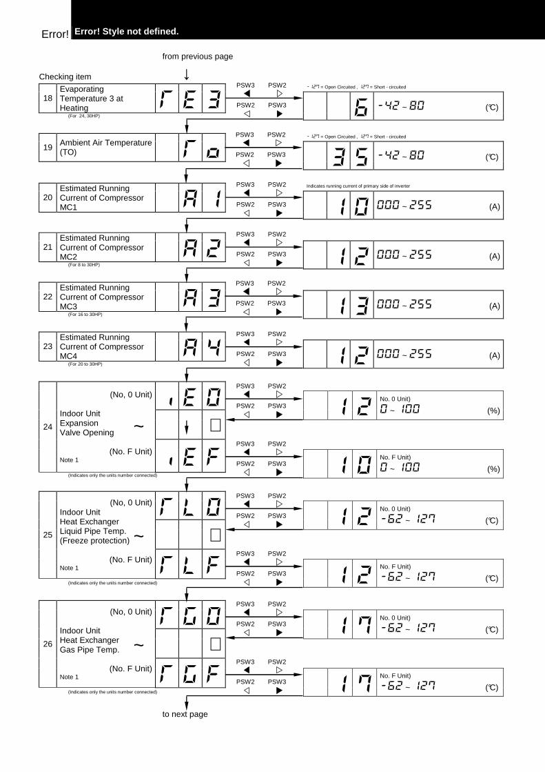
from previous page
Checking item ↓ -127 = Open Circuited , 127 = Short - circuited
18 Evaporating Temperature 3 at Heating E 3
(For 24, 30HP) 6 -42 ~ 80 (°C)
-127 = Open Circuited , 127 = Short - circuited
19 Ambient Air Temperature (TO) o
3 5 -42 ~ 80 (°C)
Indicates running current of primary side of inverter
20 Estimated Running Current of Compressor MC1 A 1
1 0 000 ~ 255 (A)
21 Estimated Running Current of Compressor MC2 A 2
(For 8 to 30HP) 1 2 000 ~ 255 (A)
22 Estimated Running Current of Compressor MC3 A 3
(For 16 to 30HP) 1 3 000 ~ 255 (A)
23 Estimated Running Current of Compressor MC4 A 4
(For 20 to 30HP) 1 2 000 ~ 255 (A)
E 0
1 2 No. 0 Unit)
0 ~ 100 (%)
∼
24
(No, 0 Unit) Indoor Unit Expansion Valve Opening
(No. F Unit) Note 1 E F
(Indicates only the units number connected)
1 0 No. F Unit)
0 ~ 100 (%)
L 0
1 2 No. 0 Unit)
-62 ~ 127 (°C)
∼
25
(No, 0 Unit) Indoor Unit Heat Exchanger Liquid Pipe Temp. (Freeze protection)
(No. F Unit) Note 1 L F
(Indicates only the units number connected)
1 2 No. F Unit)
-62 ~ 127 (°C)
! 0
1 7 No. 0 Unit)
-62 ~ 127 (°C)
∼
26
(No, 0 Unit) Indoor Unit Heat Exchanger Gas Pipe Temp.
(No. F Unit) Note 1 ! F
(Indicates only the units number connected)
1 7 No. F Unit)
-62 ~ 127 (°C)
to next page
~
~
PSW3 PSW2
PSW3 PSW2
PSW3 PSW2
PSW3 PSW2
PSW3 PSW2
PSW3 PSW2
PSW3 PSW2
PSW3 PSW2
PSW3 PSW2
PSW3 PSW2
PSW3 PSW2
PSW3 PSW2
PSW3 PSW2
PSW3 PSW2
PSW3 PSW2
PSW3 PSW2
PSW3 PSW2
PSW3 PSW2
PSW3 PSW2
PSW3 PSW2
~ PSW3 PSW2
PSW3 PSW2
PSW3 PSW2
PSW3 PSW2
Error! Style not defined. Error!
from previous page
Checking item ↓
0
2 7 No. 0 Unit)
-62 ~ 127 (°C)
∼
27
(No, 0 Unit) Indoor Unit Intake Air Temperature.
(No. F Unit) Note 1 F
(Indicates only the units number connected)
2 7 No. F Unit)
-62 ~ 127 (°C)
o 0
1 7 No. 0 Unit)
-62 ~ 127 (°C)
∼
28
(No, 0 Unit) Indoor Unit Discharge Air Temperature. (No. F Unit) Note 1 o F
(Indicates only the units number connected)
1 7 No. F Unit)
-62 ~ 127 (°C)
C A 0
8 No. 0 Unit) (x 1/8 HP)
∼
Refer to the "Capacity Code of Indoor Unit" table for the capacity code indication, page 18/6
29
(No, 0 Unit) Indoor Unit Capacity Setting.
(No. F Unit) Note 1 C A F
(Indicates only the units number connected)
2 0 No. F Unit) (x 1/8 HP)
d 1 0
1 (No. 0 Unit)
0 ~ 80
∼
Refer to the “Cause os Stoppage” table, for the code indication at page 18/5
30
(No, 0 Unit) Indoor Unit Cause of Stoppage
(No. F Unit) Note 1 d 1 F
(Indicates only the units number connected)
1 (No. F Unit)
0 ~ 80
31 Pressure Ratio Fall Protection Degeneration Control c 1 1
0 0: Degeneration Control is in Operation 1: Degeneration Control is not in
Operation
32 High-Pressure Rise Protection degeneration Control c 1 3
1 0: Degeneration Control is in Operation 1: Degeneration Control is not in
Operation
33 Discharge Gas Temp. Increase Protection Degeneration Control c 1 5
0 0: Degeneration Control is in Operation 1: Degeneration Control is not in
Operation
34 Discharge Gas Temp. Decrease Protection Degeneration Control c 1 6
0 0: Degeneration Control is in Operation 1: Degeneration Control is not in
Operation
to next page
~
~
~
~
PSW3 PSW2
PSW3 PSW2
PSW3 PSW2
PSW3 PSW2
PSW3 PSW2
PSW3 PSW2
PSW3 PSW2
PSW3 PSW2
PSW3 PSW2
PSW3 PSW2
PSW3 PSW2
PSW3 PSW2
PSW3 PSW2
PSW3 PSW2
PSW3 PSW2
PSW3 PSW2
PSW3 PSW2
PSW3 PSW2
PSW3 PSW2
PSW3 PSW2
PSW3 PSW2
PSW3 PSW2
PSW3 PSW2
PSW3 PSW2
Error! Error! Style not defined.
from previous page
Checking item ↓
35 Current Protection Degeneration Control c 1 7
0 0: Degeneration Control is in Operation 1: Degeneration Control is not in
Operation
Displayed in 4 digit number
36 Total Accumulated hours of Compressor MC1 U J 1
4 8 3 0 ~ 9999 (x 10 times hours)
Displayed in 4 digit number
37 Total Accumulated hours of Compressor MC2 U J 2
(For 8 to 30HP) 2 1 9 0 ~ 9999 (x 10 times hours)
Displayed in 4 digit number
38 Total Accumulated hours of Compressor MC3 U J 3
(For 16 to 30HP) 2 3 5 0 ~ 9999 (x 10 times hours)
Displayed in 4 digit number
39 Total Accumulated hours of Compressor MC4 U J 4
(For 20 to 30HP) 3 1 2 0 ~ 9999 (x 10 times hours)
40 The Latest Alarm Code Cause of Stoppage at Outdoor Unit A C
0 2
Refer to page 17/14 for code indication
41 Cause of Stoppage at Inverter C
9 0 ~ 11
42 Control Information F C (for 24/30 FS5 0
43 Total Quantity of Indoor Unit C P
5 2 000 ~ 240 (x 1/8 HP)
44 Address of Refrigerant System A A
8 000 ~ 016 (sets)
45 Total Capacity Setting of Combined Indoor Unit A
1 0 ~ F
Return to START "SC" Example: Indoor Unit Expansion Valve opening of Ref. Cycle No. 6 Indoor Unit No. 0
NOTE 1 – For RAS-24/30FS5, 7-segment information for all
indoor Unit data has been added one number before data, as indicated beside.
Refrigerant Cycle Adress
Checking Item
PSW3 PSW2
PSW3 PSW2
PSW3 PSW2
PSW3 PSW2
PSW3 PSW2
PSW3 PSW2
PSW3 PSW2
PSW3 PSW2
PSW3 PSW2
PSW3 PSW2
PSW3 PSW2
PSW3 PSW2
PSW3 PSW2
PSW3 PSW2
PSW3 PSW2
PSW3 PSW2
PSW3 PSW2
PSW3 PSW2
PSW3 PSW2
PSW3 PSW2
PSW3 PSW2
PSW3 PSW2
Error! Style not defined. Error!
18.4.3 RUNNING CURRENT OF COMPRESSOR � Inverter Primary Current The inverter primary current is estimated from the
running current of the compressor MC1 indicated on 7-segments, as the right chart shows.
� Indicated Running Current of Compressor
MC2, MC3, MC4 The running current of the compressor MC2, MC3,
MC4, is detected by current sensor. (CT2 ~ CT4)
Inve
rter
Prim
ary
Cur
rent
(A
)
Running Current of Compressor MC1
indicated on 7-segment � Cause of Stoppage for Inverter (Content of Check It em " C C C C")
Remark Code Cause Cause of Stoppage for
Corresponding Unit Indication during Retry Alarm Code
1 Automatic Stoppage of Transistor Module (IPM Error) (Over Current, Decrease Voltage, Increase Temperature)
17 P17 53
2 Instantaneous Over Current 17 P17 52
3 Abnormal Inverter Fin Thermistor 17 P17 54
4 Electronic Thermal Activation 17 P17 52
5 Inverter Voltage Decrease 18 P18 06
6 Increase Voltage 18 P18 06
8 Abnormal Current Sensor 17 P17 51
9 Instantaneous Power failure Detection 18 - -
11 Reset of Micro-Computer for Inverter 18 - -
12 Earth Fault Detection for Compressor (Only Starting) 17 P17 53
13 Abnormal Power Source Phase 18 - -
Lower Limit
Upper Limit

Error! Error! Style not defined.
18.5 PROTECTION CONTROL CODE ON 7-SEGMENT DISPLAY
1. The protection control indication can be seen on 7-segment when a protection control is activated.
2. The 7-segment continues ON while function is working, and goes out when released.
3. When several protection controls are activated, code number with higher priority will be indicated (see below for the priority order).
� Higher priority is given to protection control related to frequency control than the other.
Priority Order:
� Pressure Ratio Control
� High-Pressure Rise Protection
� Current Protection
� Discharge Gas Temperature Rise Protection
� Low-Pressure Fall Protection
� Reversing Valve Switching Control (For 16, 20HP and FS(3/5) Series)
� High-Pressure Decrease Protection
� Oil Return Control
� Running Current Limit Control (for 24/30 FS5)
� In relation to retry control, the latest retrial will be indicated unless a protection control related to frequency control is indicated.
Code Protection Control
p 0 1 Pressure Ratio Control (*)
p 0 2 High-Pressure Increase Protection (*)
p 0 3 Current Protection (*)
P 0 4 Inverter Fin Temp. Increase Protection (for 24, 30HP)
p 0 5 Discharge Gas Temperature Increase Protection (*)
p 0 6 Low-Pressure Decrease Protection
p 0 7 4-Way Valve Switching Control (For 16, 20HP)
p 0 8 Oil Return Control
p 0 9 High-Pressure Decrease Protection
P 0 A Running Current Limit Control (for 24, 30 FS5
p 1 1 Pressure Ratio Decrease Retry
p 1 2 Low-Pressure Increase Retry
p 1 3 High-Pressure Increase Retry
p 1 4 Over Current Retry of Constant Compressor
p 1 5 Vacuum/Discharge Gas Temperature Increase Retry
p 1 6 Discharge Gas SUPERHEAT Decrease Retry
p 1 7 Inverter Trip Retry
p 1 8 Insufficient Voltage / Excessive Voltage Retry
In the case that degeneration control is activated, is indicated instead of (*mark)
- Retry indication continues for 30 minutes unless a protection control is indicated.
- Retry indication disappears if the stop signal comes from all rooms.
NOTE: The protection control code being indicated on
7-segment display is changed to an alarm code when the abnormal operation occurs. Also, the same alarm code is indicated on the remote control switch.
Error! Style not defined. Error!
� ACTIVATING CONDITION OF PROTECTION CONTROL CODE For following the conditions as the temperature change, etc., the control of frequency, etc. is performed to prevent the abnormal conditions by the protection control.
The activating conditions of protection control are shown in the table below.
Code Protection Control Activating Condition Remarks
Pressure Ratio Control
Compression Ratio ≥ 9 → Frequency Decrease (Pd/(Ps+1.3)) ≤ 2.2 → Frequency Increase
Ps: Suction Pressure of Compressor
High-Pressure Increase Protection Pd ≥ 2.4 Mpa → Frequency Decrease
Pd: Discharge Pressure of Compressor
Current Protection Inverter Output Current ≥ 25A (220 V), 14A (380, 415V) → Frequency Decrease
-
Inverter Fin Temperature Increase Protection Inverter Fin Temperature ≤ 94 °C → Frequency Decrease -
Discharge Gas Temperature Increase Protection
Temperature at the top of compressor is high → Frequency Increase (Maximum temperature is different depending on the frequency.)
-
Low-Pressure Decrease Protection
Low-Pressure Is Excessively Low → Frequency Increase (Minimum pressure is different depending on the ambient temperature.)
-
For 16, 20HP
When Switching, ∆P<0.5MPa → Frequency Increase ∆P<1.3MPa → Frequency Decrease
4-Way Valve Switching Control For
24, 30HP
When Switching, ∆P<1.0MPa → Frequency Increase ∆P<2.1MPa → Frequency Decrease
∆P = Pd - Ps
For 5, 20HP
Frequency less than 40Hz is maintained for more than 1 hour → Frequency ≥ 40Hz
Oil Return Control For
24, 30HP
Frequency less than 120Hz at cooling (150Hz at heating) is maintained for more than 1 hour → Frequency ≥ 120Hz at cooling (150Hz at heating).
-
High-Pressure Fall Protection
Pd ≤ 0.69MPa → Frequency Increase (When Cooling Operation) Pd ≤ 1.42Mpa → Frequency Increase (When Heating Operation)
Pd: Discharge Pressure of Compressor
Running Current Limit Control (for 24, 30HP
Running Current for Comp. ≥ Setting Value → Frequency Decrease
Setting Value: Upper limit of total running current is set 80%, 70% and 60% at normal operation using input on PCB.
Pressure Ratio Decrease Retry
Compression Ratio (Pd/(Ps+1.3)<1.8) When activating 3 times in an hour, “43” alarm is indicated.
Low-Pressure Increase Retry Ps>0.9MPa When activating 3 times in an hour,
“44” alarm is indicated.
For 5 to 20HP
Pd>2.65MPa (In case of 20 ~ 30Hz: Pd>2.5MPa)
High-Pressure Rising Retry For
24, 30HP Pd>2.65MPa
When activating 3 times in an hour, “45” alarm is indicated.
Overcurrent Retry of Constant Compressor Current ≥ Maximum Value(*1), or Current<0.9A
When activating 3 times in an hour, “39” alarm is indicated.
Vacuum/Discharge Gas Temperature Rising Retry
In Case of Ps<0.02MPa over 12 minutes, Discharge Gas Temperature ≥ 132°C over 10 minutes or Discharge Gas Temperature ≥ 140 °C over 5 seconds
When activating 3 times in 30 minutes, “47”(Ps) or “08” (Discharge Gas) alarm is indicated.
For 5 to 20HP
Discharge Gas SUPERHEAT less than 10 deg. is maintained for an hour
Discharge Gas SUPERHEAT Decrease Retry
For 24, 30HP
Discharge Gas SUPERHEAT less than 10 deg. is maintained for 30 minutes.
When activating 2 times in 2 hours (90min. for 24, 30HP), “07” alarm is indicated.
Inverter Trip Retry Automatic Stoppage of Transistor Module, Activation of Electronic Thermal or Abnormal Current Sensor
When activating 3 times in 30 minutes, “51”, “52” and “53” alarm is indicated.
Insufficient Voltage / Excessive Voltage Retry
Insufficient/Excessive Voltage at Inverter Circuit or CB Connector Part
When activating 3 times in 30 minutes, “06” alarm is indicated.

Error! Error! Style not defined.
NOTE: 1. During protection control (except during alarm
stoppage), the protection control code is indicated.
2. The protection control code is indicated during protection control and turns off when canceling the protection control.
3. After retry control, the condition of monitoring is continued for 30 minutes.
4. The maximum value (*1) is as follows:
Model 380-415V 50 Hz 380V 60 Hz
8HP 12.1A 12.6A
10HP 15.0A 15.8A
16HP 17.8A 18.8A
20HP 17.8A 18.8A
Model Comp. 1 Comp. 3, 4 Comp. 2 Comp. 3, 4
24HP 17.8A 21.6A 18.8A 22.8A
30HP 17.8A 31.7A 18.8A 33.4A
Error! Style not defined. Error!
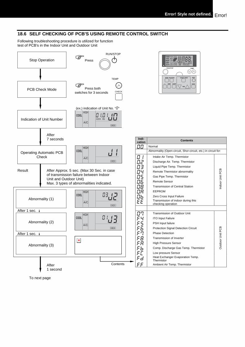
18.6 SELF CHECKING OF PCB'S USING REMOTE CONTROL SW ITCH
Following troubleshooting procedure is utilized for function test of PCB's in the Indoor Unit and Outdoor Unit
Stop Operation
�Press
PCB Check Mode
�Press both switches for 3 seconds
(ex.) indication of Unit No. "0"
Indication of Unit Number
After 7 seconds
Operating Automatic PCB Check
Result After Approx. 5 sec. (Max 30 Sec. in case
of transmission failure between Indoor Unit and Outdoor Unit) Max. 3 types of abnormalities indicated.
Abnormality (1)
After 1 sec. ↓↓↓↓
Abnormality (2)
After 1 sec. ↓↓↓↓
Abnormality (3)
After 1 second
To next page
RUN/STOP
Indi-cation Contents
00 Normal
Abnormality (Open-circuit, Shor-circuit, etc.) in circuit for:
01 Intake Air Temp. Thermistor
02 Discharge Air. Temp. Thermistor
03 Liquid Pipe Temp. Thermistor
04 Remote Thermistor abnormality
05 Gas Pipe Temp. Thermistor
06 Remote Sensor
08 Transmission of Central Station
0A EEPROM
Ob Zero Cross Input Failure
EE Transmission of indoor during this checking operation
Indo
or U
nit P
CB
07 Transmission of Outdoor Unit
F4 ITO Input Failure
F5 PSH Input failure
F6 Protection Signal Detection Circuit
F7 Phase Detection
F8 Transmission of Inverter
FA High Pressure Sensor
Fb Comp. Discharge Gas Temp. Thermistor
FC Low pressure Sensor
Fd Heat Exchanger Evaporation Temp. Thermistor
FF Ambient Air Temp. Thermistor
Out
door
Uni
t PC
B
Contents
TEMP
CHECK
Error! Error! Style not defined.
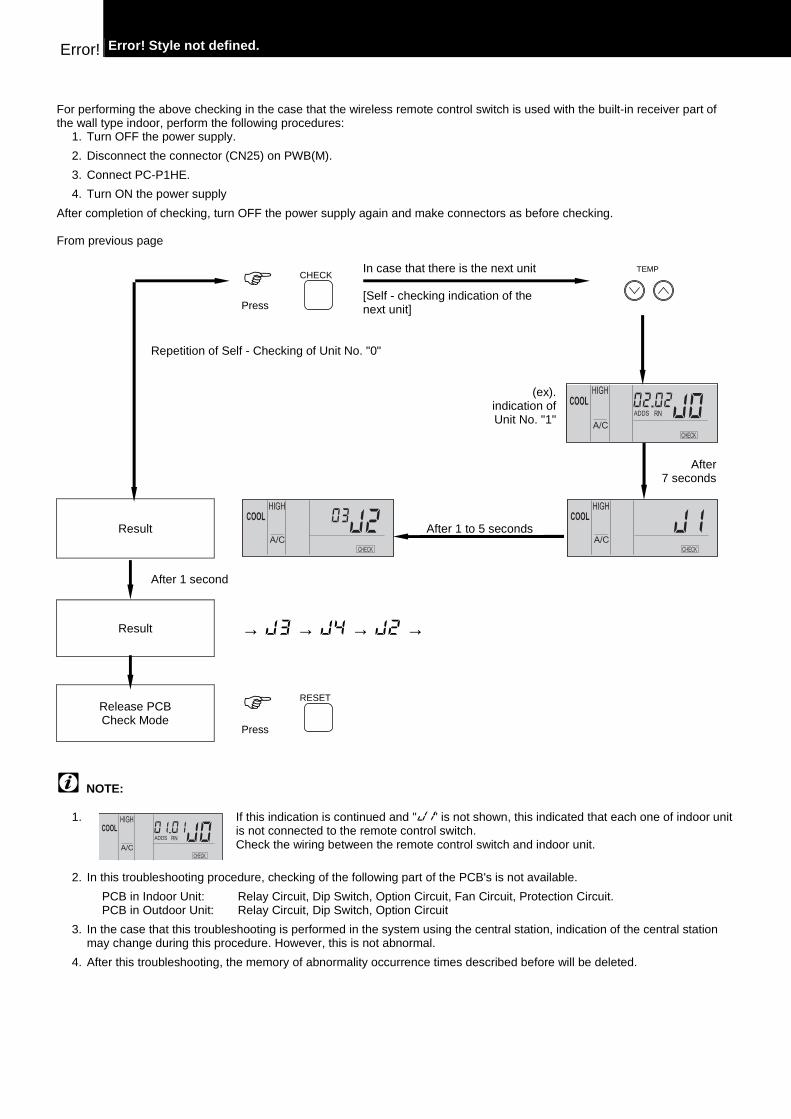
For performing the above checking in the case that the wireless remote control switch is used with the built-in receiver part of the wall type indoor, perform the following procedures:
1. Turn OFF the power supply.
2. Disconnect the connector (CN25) on PWB(M).
3. Connect PC-P1HE.
4. Turn ON the power supply
After completion of checking, turn OFF the power supply again and make connectors as before checking. From previous page
�
Press
In case that there is the next unit [Self - checking indication of the next unit]
Repetition of Self - Checking of Unit No. "0"
(ex). indication of Unit No. "1"
After 7 seconds
Result
After 1 to 5 seconds
After 1 second
Result
→ J3 → J4 → J2 →
Release PCB Check Mode
�
Press
NOTE:
1. If this indication is continued and "J1" is not shown, this indicated that each one of indoor unit is not connected to the remote control switch. Check the wiring between the remote control switch and indoor unit.
2. In this troubleshooting procedure, checking of the following part of the PCB's is not available.
PCB in Indoor Unit: Relay Circuit, Dip Switch, Option Circuit, Fan Circuit, Protection Circuit. PCB in Outdoor Unit: Relay Circuit, Dip Switch, Option Circuit
3. In the case that this troubleshooting is performed in the system using the central station, indication of the central station may change during this procedure. However, this is not abnormal.
4. After this troubleshooting, the memory of abnormality occurrence times described before will be deleted.
CHECK
RESET
TEMP
Error! Style not defined. Error!
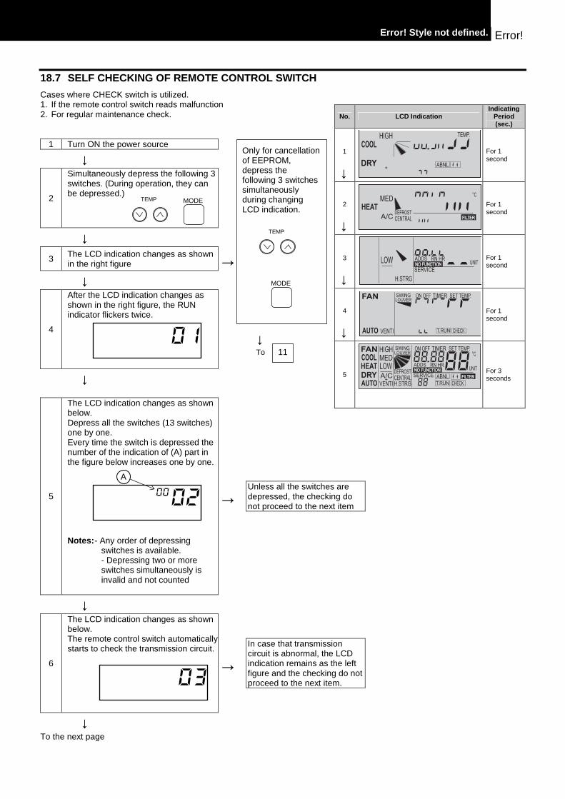
18.7 SELF CHECKING OF REMOTE CONTROL SWITCH
Cases where CHECK switch is utilized. 1. If the remote control switch reads malfunction 2. For regular maintenance check.
1 Turn ON the power source
↓
2
Simultaneously depress the following 3 switches. (During operation, they can be depressed.)
↓
3 The LCD indication changes as shown in the right figure →
↓
4
After the LCD indication changes as shown in the right figure, the RUN indicator flickers twice.
↓ To
↓
5
The LCD indication changes as shown below. Depress all the switches (13 switches) one by one. Every time the switch is depressed the number of the indication of (A) part in the figure below increases one by one. Notes: - Any order of depressing
switches is available. - Depressing two or more switches simultaneously is invalid and not counted
→
Unless all the switches are depressed, the checking do not proceed to the next item
↓
6
The LCD indication changes as shown below. The remote control switch automatically starts to check the transmission circuit.
→
In case that transmission circuit is abnormal, the LCD indication remains as the left figure and the checking do not proceed to the next item.
↓ To the next page
Only for cancellation of EEPROM, depress the following 3 switches simultaneously during changing LCD indication.
No. LCD Indication Indicating
Period (sec.)
1
↓
For 1 second
2
↓
For 1 second
3
↓
For 1 second
4
↓
For 1 second
5
For 3 seconds
0200
A
03
MODE
MODE
0111
TEMP
TEMP

Error! Error! Style not defined.
↓
7
The LCD indication changes as shown below. The detected temperature of remote control thermostat is indicated at the part (A) part in the figure below.
→ If the number "--" or "FF" is indicated at the "A" part, the remote control thermostat is abnormal.
↓
8
The LCD indication changes as shown below.
→
↓
9
The LCD indication changes as shown below. After several seconds are passed, the remote control switch is automatically activated again.
←
In case of depressing the RESET switch or leaving the switches for 15 seconds, the data of EEPROM (storage cell inside of the remote control switch) is cleared. At this time, the number is indicated at the (A) part shown in the figure below. When the number "99" is indicated, EEPROM is abnormal. The number indicated at the (A) part is "99", the checking do not proceed to the next time
↓ Cancellation of EEPROM
11
The LCD indication changes as shown below and the EEPROM is automatically cancelled by the remote control switch
10
When the remote control switch is activated again, the RUN indicator is ON and the operation is started. Therefore, depress RUN/STOP switch and stop operation.
NOTE: 1. In case that the operation is not
automatically started when the remote control switch is activated again, the detection circuit for momentary stoppage may be abnormal. However, it would not interfere the normal operation.
2. There is a case that the operation is automatically stopped after the automatic operation when the remote control switch is activated again.
12
The LCD indication changes as shown below After several seconds are passed, the remote control switch is automatically activated again. In this case, the operation is not started automatically.
04 20
A
05 00
A
05
06
07
08
3
↓