resolve project - nasa€¦ · al·~~ nasa access - internship final report regolith and...
TRANSCRIPT

NASA ACCESS- Internship Final Report
RESOLVE Project
Ray 0. Parker
John F. Kennedy Space Center
Major: Chemical Engineering
ACCESS Program Summer Session
Date: 08 07 2013
John F. Kennedy Space Center 7/8/2013
https://ntrs.nasa.gov/search.jsp?R=20140002619 2020-04-19T15:47:16+00:00Z

~~-~ Al ·~~
NASA ACCESS - Internship Final Report
Regolith and Environment Science &
Oxygen and Lunar Volatile Extraction (RESOLVE)
Project
RayParker1
Rensselaer Polytechnic Institute, John F. Kennedy Space Center, Florida, 32899
Mentors: Dr. Janine Captain2, Dr. Mary Coan3
, Kate Cryderman4
1 NASA ACCESS Intern, NE-LS, Kennedy Space Center, Rensselaer Polytechnic Institute. 2 PhD, Lead AST Aerospace Polymeric Materials, NE-LS, Kennedy Space Center, Georgia Institute of Technology. 3 PhD, AST Aerospace Polymeric Materials, NE-LS, Kennedy Space Center, Texas A&M University. 4 AST Flight Systems Test, NE-M3, Kennedy Space Center, University of Michigan.
John F. Kennedy Space Center ii 7/8/2013

NASA ACCESS - Internship Final Report
Table of Contents Education Office Cover Page
RESOLVE Cover Page
Table of Contents
Nomenclatures, Abbreviations, Acronyms, and Symbols
Abstract
I. Introduction
II. Procedures and Testing
A. PT Testing Procedure
B. RID Procedure
C. Heat Wrap Analysis Testing
D. Gold Deposition Trade Study
E. Mini-Manifold Testing
III. Analysis and Results
A. PT Testing Results
B. RID Procedure Results
C. Heat Wrap Analysis Results
D. Gold Deposition Trade Study Results
E. Mini-Manifold Test Results
N. Conclusion and Recommendations
V. Acknowledgments
VI. References
John F. Kennedy Space Center iii
11
m
IV
1
3
3
5
7
10
11
13
13
13
13
15
16
18
18
19
7/8/2013

NASA ACCESS - Internship Final Report
N I t omenc a ures, Abb ·r rev1a Ions, A cronyms, an dS •YID b I OS Term Definition oc Degrees Celsius ACCESS Achieving Competency in Careers in Engineering and Space Sciences ACL Applied Chemistry Laboratory APL Applied Physics Laboratory ATM Atmosphere cc Cubic Centimeters ci Cubic Inches ESD Electrostatic Discharge ETU Engineering Test Unit FSS Fluid Subsystem FTU Field Test Unit g Grams GC Gas Chromatograph GSE Ground Support Equipment GSS Gas Supply System IPA Isopropyl Alcohol JPL Jet Propulsion Laboratory K Kelvin kg Kilograms KSC Kennedy Space Center LAVA Lunar Advanced Volatile Analysis MCOTS Modified Commercial off the Shelf MS Mass Spectrometer NE-L5 Applied Physics Laboratory Mail Code NIRST Near Infrared Spectrometer for Surge Tank OVEN Oxygen Volatile Extraction Node PID Proportional-Integral-Derivative PPE Personal Protective Equipment psi a Pounds per Square Inch at Atmospheric Pressure PT Pressure Transducer QA Quality Assurance RESOLVE Regolith and Environment Science and Oxygen and Lunar Volatile Extraction ROE Regolith Oxygen Extraction RTD Resistive Temperature Detector SBU Sensitive But Unclassified SDS Sample Delivery System ss Stainless Steel ST LAVA Surge Tank TEC Thermal Electric Cooler TS Temperature Sensors UHP Ultra High Purity (99.999%) VA Volatile Analysis WDD Water Droplet Demonstration
Chemical Formula (Mass) Name Chemical Formula (Mass) Name · H20 {18 g/mol) Water H2S (34.08 g/mol) Hydrogen sulfide CO (28.05 g/mol) Carbon monoxide NH3 (28.01 g/mol) Ammonia 0 2 (32 _g/mol) Oxygen so2 (64.07 g/mol) Sulfur dioxide C2H4 (28 g/mol) Ethylene OH ( 17 g/mol) Hydroxide C02 (44.01 g/mol) Carbon dioxide HF (20.01 g/mol) Hydrogen fluoride H2 (2 g/mol) Hydrogen HCl (36.46 g/mol) Hydrochloric acid
John F. Kennedy Space Center iv 7/8/2013

NASA ACCESS- Internship Final Report
Abstract. The RESOLVE project is a lunar prospecting mission whose primary goal is to characterize water and other volatiles in lunar regolith. The Lunar Advanced Volatiles Analysis (LAVA) subsystem is comprised of a fluid subsystem that transports flow to the gas chromatograph -mass spectrometer (GC-MS) instruments that characterize volatiles and the Water Droplet Demonstration (WDD) that will capture and display water condensation in the gas stream. The LAVA Engineering Test Unit (ETU) is undergoing risk reduction testing this summer and fall within a vacuum chamber to understand and characterize component and integrated system performance. Testing of line heaters, printed circuit heaters, pressure transducers, temperature sensors, regulators, and valves in atmospheric and vacuum environments was done. Test procedures were developed to guide experimental tests and test reports to analyze and draw conclusions from the data. In addition, knowledge and experience was gained with preparing a vacuum chamber with fluid and electrical connections. Further testing will include integrated testing of the fluid subsystem with the gas supply system, near-infrared spectrometer, WDD, Sample Delivery System, and GC-MS in the vacuum chamber. This testing will provide hands-on exposure to a flight forward spaceflight subsystem, the processes associated with testing equipment in a vacuum chamber, and experience working in a laboratory setting. Examples of specific analysis conducted include: pneumatic analysis to calculate the WDD's efficiency at extracting water vapor from the gas stream to form condensation; thermal analysis of the conduction and radiation along a line connecting two thermal masses; and proportional-integral-derivative (PID) heater control analysis. Since LAVA is a scientific subsystem, the near-infrared spectrometer and GC-MS instruments will be tested during the ETU testing phase.
I. Introduction NASA exploration of extraterrestrial bodies is increasingly growing as well as what materials that can be gained
from these lunar bodies. In future human exploration of space, NASA has an increasing interest in obtaining resources from outside of our own planetary system and using these resources as essential resources to help humans survive in the unforgiving climates of space, and lunar bodies such as Mars.
The RESOLVE project is a lunar prospecting mission whose primary goal is to characterize water and other gas volatiles in lunar regolith. RESOLVE consists of LAVA, OVEN, Avionics, Software, Thermal and Structures Subsystems. The Lunar Advanced Volatiles Analysis (LAVA) subsystem, interfaces with all of the other RESOLVE subsystems, is comprised of a fluid subsystem that transports flow to the gas chromatograph - mass spectrometer (GC-MS) instruments that characterize volatiles and the Water Droplet Demonstration (WDD) that will capture and display water condensation in the gas stream. In addition to being comprised of the GC and MS, LAVA is also made up by the SDS, FSS and GSE. The Fluid Subsystem is primarily what will be focused on during the duration of this report, and includes the NIRST, WDD, Integrated Manifold and GSS. The Integrated Manifold consists of the Manifold, Heaters, Pressure Transducers (PT), Temperature Sensors (TS), and Orifices/Tubing.
The RESOLVE rover will be sent to prove that water can be accessible on the moon and other planetary bodies, and that there is enough regolith, or lunar soil, to make air for astronauts, fuel for rockets, or water for plants. The rover will look for essential gases inside of craters, where the remains of comets (made of ashes, dust and iced water) will be located. The rover will then use its drill, which is designated to burrow a yard into the lunar soil to extract soil, of which will be put into the OVEN. OVEN will then heat the soil, which will release the gas particles into a streamline to lead to the STINIR.ST, which will then vent the fast flowing gas molecules to the SDS/GC-MS, or WDD subsystems.
While inside of the ST, the GC-MS analyzes the mass of the particles using the near infrared spectrometer to determine the identity of the particles. The GC-MS will allow for scientific data to be transmitted back to Earth to provide more information on particles of matter on other planetary bodies. The gas inside of the ST can also go to the WDD or Water Droplet Demo, ran through ROE, or can be vented out of the system. Within the WDD, the particles of gas (CO, C02, H20, H2, H2S, NH3, S02, C2H4, HF and HCl) are moved into the system along with hydrogen gas that ejects into the WDD as well, causing the OH molecules to condense inside of the WDD causing water droplets to form in the state of condensation. A picture will be taken of the processes and will be sent back to Earth, showing that water can be made on the moon or another planetary body with the right conditions.
John F. Kennedy Space Center Page 1 7/8/2013

NASA ACCESS - Internship Final Report
I
1 ... _ . I;;::-.::.-
~·~-=R~~~-- -&-·-····- -· 1 ... ::.::.·. .. ..
__,. J•f .......
........ -.........
• ,,,,..._.- .,~~r•·• .,._,.__, --t• ..,,..,. .,.. ~,. .,,, ,, ...... .._._ ~ _..,,.,, . .,,. f. •·-·•',
~. -·- - ... -· ___ ... .... ------· ~ ._.,...., .... -~ ...
~.uJ•t<ll"'-'" .. . .-.~o .. ..,,... ... ~> .·• ~ 'l''-11f r• · - ~.., .._ , .. , _ _..::. • ., .,. .. ,,..,"'-,.. .. . -~ ... -· - ....... ~ ...... ~- t•··-....... - . ..... ......... --- ..... ~ .. ,.. ............ ,.-'\.., .. ,., ... .. ,. .. ~ . ...,
WDD
-! i r ~i !•
Figure 1. RESOLVE Subsystem ETU Layout. LA VA Subsystem is depicted inside box, with the WDD and fluid valves/lines on the right, and the OVEN/G{!;-MSISDS subsystems on the left.
Regolith Oxygen Extraction (ROE) is a process that involves LAVA and OVEN, and is the same procedure as before, but instead at a much higher temperature. OVEN heats the regolith to 900°C, instead Qf 150°C, and Hydrogen is supplied and reacts with the oxygen in the regolith to form water which flows into the ST. Fluoride and other unwanted species can also react with the hydrogen at high temperatures and form acidic species. Along with the more gaseous molecules, fluoride ions and other unwanted molecules may be present and bond with the existing molecules to cause complications, of which could damage or lower the accuracy of the instruments. Because of this, ROE will not be used until RESOLVE has completed all other essential tasks, such as the WDD or GC-MS analysis.
The rover is to complete its mission in I 0 days on the moon and projected to last no more than a month on the
Figure 2. RESOLVE Moon Rover Field Test Unit. The LAVA subsystem is depicted in the black box on the rover. Photo credit:
NASA/Dmitri Gerondidakis moon, due to large temperature drops on the inside of the craters on the moon. RESOLVE is a combined effort between the National Aeronautics and Space Administration (NASA), NASA's John F. Kennedy Space Center, NASA's Jet Propulsion Laboratory (JPL), NASA's Ames Research Center' (ARC) and the Canadian Space Agency
John F. Kennedy Space Center Page2 7/8/2013

NASA ACCESS - Internship Final Report
Figure 3. RESOLVE Rover Field Test Unit. RESOLVE rover being tested on the
Hawaiian Islands (Big Island). Photo credit: NASA/Joe Bibby
(CSA). The RESOLVE project started out as an exploratory project that took the proven concept using a hydrogen reduction reaction and adding Hydrogen to react with oxides in soil and form water. It was then expanded to prove that this concept would be able to be done on another terrestrial body, other than the Earth, in order to make essential resources, such as water, on the moon or Mars. NASA is working towards using the few resources on other terrestrial bodies and turning them into resources that will help discover the rest of the solar system. RESOLVE is a Class D mission and the mission payload is expected to fly in 2018 .
The duration of the internship focuses mainly on the LAVA and FSS subsystem. Procedure writing, testing and analysis were all done on certain aspects of the ETU build. The following will address developed procedures and experiments, along with the results of the experiments and their effect on the RESOLVE ETU rover.
II. Procedures and Testing
The FSS is currently in the ETU testing phase, in which certain factors from the FTU are being modified to be better suited for flight mission. Testing was all done for the FSS, in which certain factors and concepts were tested and figured to be favored over the other. This internship focuses on testing, analyzing and evaluating certain points on the FSS FTU and modifying them for maximum efficiency. Pressure Transducers were tested for repeatability. RTD Experimental Procedures were modified and improved for further efficiency. Heat wrapping was analyzed for maximum heating and efficiency. Abstract modification concepts were researched and analyzed for the Gold Deposition Trade stud and experimentation thinking and pneumatic analysis were done on the Mini-Manifold Analysis Testing. All procedures that were done in this section were done in O&C Laboratory 1292, under supervision of Mary Coan, Janine Captain, Lucas Lance, Kate Cryderman and/or Beau Peacock. All procedures will be addressed in Section II , follow by results in Section III and conclusion in Section IV.
A. PT Testing Procedure
Pressure Transducer testing was done to help ensure repeatability of the PT's inside of the vacuum chamber and at atmospheric pressure. The PT testing was done using a LabView Program and an experimental manifold setup with National Instrument NI adaptor sensors, of which were set up by Beau Peacock.
The PT testing comprised of taking the experimental setup and utilizing pressure changes in conjunction with temperature changes. The PT's are used as pressure regulators inside of the manifold, while the rover is running. Temperature was kept constant, while the pressure of the system was changed in certain increments, each of which lasted about seven or so minutes. Pressure started at ATM, went to 25 pisa (pounds per square inch absolute), 50 pisa, 75 pisa, 100 pisa, and then back down to 75 pisa, 50 psia, 25 pisa, and then back to ATM. Each test took about 30 minutes to complete, and each temperature level, (25°C, 50°C, 75°C, 100°C, 150oC and 175°C) needed to be tested three times each for repeatability and quality assurance.
There will be three PT's that will be used inside of the Integrated Manifold for ETU, which will help transfer fluids and gases along their expected paths. RTD 's (Resistance Thermal Detectors) are placed onto the surface of each PT and the PT's were to be tested inside of a vacuum chamber during the Mini-Manifold Test Procedure and during the functioning test of the completed manifold setup in the future.
All pressure transducers that were used were manufactured by kulite.
John F. Kennedy Space Center Page 3 7/8/2013

120
100
e 80 .... .e r- .. Ill 60 ~
::J Ill Ill I'"' .. Ill
40 ~
Q.
20 ,.. .., ~ L...
0 m lD N N N .-I .-I
m en en m ,..... .-I Ll) lD lD N lD en m lD m 0 m lD 0 m
.-I .-I .-I N N
Time (ms)
24.6
24.5
24.4 -k 24.3
~ 24.2 ::J -;a 24.1 ~
Ill 24 c. E
23.9 Ill 1-
23.8
23 .7
23.6 m .-I N m ,..... m m N <::t N N .-I
lD Ll) .-I m N m m ,..... .-I Ll) en N
.-I .-I
Time (ms)
NASA ACCESS - Internship Final Report
- Pressure Standard
- TC Manifold
0.03
0.025
-~ 0.02 Ill ~
::J -;a 0.015 ... Ill c. ~ 0.01 1-
0.005
~
"""" I.
..
0 lf 1... m .-I N m ,..... m m N <::t N N .-I
lD Ll) .-I m N m m ,..... .-I Ll) en N
.-I .-I
Time (ms)
4.093
4.0925
-0
~ 4.092 Ill ~
::J -;a 4.0915 ... Ill c. E Ill
4.091 1-
4.0905
4.09 m.-tNmr-.m • • <::t • • .-I mN.-~NNm
*~.-t~d::N .-I .-I
Time (ms)
- PTVoltage
- PTVoltage Supply
Figure 4. Pressure Transducer Testing Outputs. Testing outputs includes pressure (top left), voltage applied (top right), temperature (bottom left), and voltage supply (bottom right).
John F. Ke1medy Space Center Page4 7/8/2013

NASA ACCESS - Internship Final Report
B. RTD Procedure
The LAVA Resistance Temperature Detector (RTD) Test will allow for a wide range of temperatures that will emulate the operational and non-operational modes throughout the mission lifetime. Testing the RTD at 14.7 psia, or Earth's Atmosphere, affords the designer the ability to discriminate phenomenon and error associated with the vacuum of space.
Testing the RTD in a vacuum equal to or below lxl0-5 torr affords the designer the ability to discriminate phenomenon and error associated with Earth's Atmosphere and allows the RTD to function in an environment similar to the Moon. An oven will be used to heat and cool an isothermal block that the RTDs will be mounted to in earth's atmosphere. A temperature standard will be used in the oven to verify the accuracy of the RTD unit under test in earth's atmosphere and in vacuum. The RTD's will be attached to certain parts of the manifold and rover to help determine temperature and be used as a feedback control regulator.
I RTOModel
Keep the more flat
end of the RTO on
the bottom/closest
to the manifold
(See best practices)
Figure 5. RTD Model. A picture showing the proper side to mount to the metal surface in this experiment.
Lab View 9219
~-------------------------1 1 Vacuum Chamber, 1
~ lxl0-7 Torr via a Turbo Pump :
I I I
l--------------------- ---_I Figure 6. LAVA Resistance Temperature Detector Experimental Test Set-up in Vacuum.
(Provided by Mary Coan)
The adhesion of an RTD to a metal consists of taking a silicon adhesive and applying the RTV onto a metallic surface and placing in a RTD onto it in order to create a sustaining vacuum-rated sealant, temperature sensor and bond network. The adhesive is made using a liquid part and solid part of which should be weigh and mixed according to the data sheet provided for the specific adhesive. Keep in mind that the adhesive has a short working life time, so be sure to consult a data sheet prior to mixing to ensure enough time will be available. Utilize pre-wired RTD's, this way soldering does not damage or destroy manifold or component with the RTD on it.
John F. Kennedy Space Center Page 5 7/8/2013
NASA ACCESS - Internship Final Report
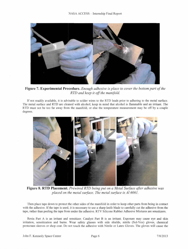
Figure 7. Experimental Procedure. Enough adhesive is place to cover the bottom part of the RTD and keep it off the manifold.
If not readily available, it is advisable to solder wires to the RTD leads prior to adhering to the metal surface. The metal surface and RTD are cleaned with alcohol; keep in mind that alcohol is flammable and an irritant. The RTD must not be too far away from the manifold, or else the temperature measurement may be off by a couple degrees.
Figure 8. RTD Placement. Prewired RTD being put on a Metal Surface after adhesive was placed on the metal surface. The metal surface is Al6061.
Then place tape down to protect the other sides of the manifold in order to keep other parts from being in contact with the adhesive. If the tape is used, it is necessary to use a sharp knife blade to carefully cut the adhesive from the tape, rather than peeling the tape from under the adhesive. RTV Silicone Rubber Adhesive Mixtures are sensitizers.
Resin Part A is an irritant and sensitizer. Catalyst Part B is an irritant. Exposure may cause eye and skin irritation, sensitization and burns. Wear safety glasses with side shields, nitrile (Sol-Vex) gloves, chemical protectant sleeves or shop coat. Do not touch the adhesive with Nitrile or Latex Gloves. The gloves will cause the
John F. Kennedy Space Center Page 6 7/8/2013

NASA ACCESS - Internship Final Report
adhesive to chemically break down. If adhesive must be touched, utilize PVC gloves. Do not place the adhesive or RTD wires where the potential to block vital functions is possible such as bolts, screws, moving devices, etc. The RTD leads shall not touch the metal surface or each other. Cover the leads with tape before curing and solder joints with vacuum rated heat shrink, if prewired RTDs are used. If the leads touch each other or the manifold surface, a short may occur and could be grounded out.
Figure 9. Complete Product. Completed RTD attachment to a flat metal surface (no wires).
The RTD is placed on the adhesive using tweezers. The RTD is pressed into the adhesive using the adhesiveapplying tool, and then a piece of tape is placed over the RTD wires while pressing the RTD down. Cover the entire RTD and exposed leads with additional adhesive. The adhesive shall be cured according to the manufacturer data sheets. Using thermal protective gloves, remove the mounted surface and the attached RTDs from the oven ensuring due care while handling the assembly. Heat generating equipment produces high surface temperatures. Contact with hot equipment or heated materials may cause severe burns. Usage near combustible materials, vapors or ordnance may result in ftre and/or explosion causing severe injury or death. Flat surface of the RTD must be in contact with the metal surface in order to ensure accuracy in temperature reading. Tape may be advised to be kept on until soldering is started, due to the possibility of reattaching the RTD and adhesive from the metallic surface.
In order to check if the RTD is working properly, a voltmeter or multi-meter is taken and put onto resistance measurement setting. The two leads are then touched by the two multi-meter probes and the resistance is taken. RID's should have around one kilo-ohm of resistance. While touching one probe to the wire, take the other probe and touch the piece of tubing to make sure no ohms are being recorded. Then take the other leads and make sure it doesn' t have any resistance reading. Testing reduces the chances of the RTD's grounding out or failing during testing and ensures quality of the RTD adhering procedure. If the RTD is coming out of the adhesives or is not laid flat against the manifold or tubing, the entire procedure must be redone. Adhering RTD's can be difficult but can be made easier by having two appliers.
C. Heat Wrap Analysis Testing
The goal during the heat wrap analysis test is to determine the most efficient method to heat trace l/8th inch stainless steel tubing that minimizes heat loss and uneven heat distribution. Thermal proftle will help to determine the cooler spots along the tube, where the RTD's will be placed. This will also help us determine the most effective method of wrapping the line heater onto the tube. The data and conclusion collected here will help determine which type of wrapping style will be used on the ETU. The testing of the line heater wrap for initial testing has concluded that for wrapping line heater around a 6 inch tube that; 3 Wraps/in - 27 inches of heater per 1 foot tube, 2 Wraps/in - 16 inches of heater per 1 foot tube, 1 Wraps/in - 13.5 inches of heater per 1 foot tube. Thermal images/heat profiles of each of the tubes were taken to see which wrapping method would be most effective and what will be used for the remainder of the ETU design.
John F. Kennedy Space Center Page 7 7/8/2013

NASA ACCESS - Internship Final Report
Figure 10. Heat Wrap Testing Setup. Testing setup, complete with thermocouple, power supply, voltmeter (for temperature measurement) and tubing with line heater wrap.
The installation of the Heat Wrap or line heater consists of taking a stainless steel tube, cutting it at a specific length and having enough line heaters to cover the piece of tubing. An exacto-knife is used to take the ends of the line heater and open each side up and exposing the wires. A protective flap to cover the exposed area of wire is needed. The surface layer covering on each side was scrapped off with the exacto-knife. The wire is very fragile after being crimped together; do not put stress on it. On one side of the line heater, twist the two wires together and crimp it off. With the other side of the line heater, take the non-crimped end and crimp one of the line heater wires to a normal wire, and crimp the other line heater wire onto another separate wire.
Line Heater Wire Wire
Line Heater Wire (Stripped)
Figure 11. Wiring Setup (Internal Diagram)
Line Heater Wire Wire
Line Heater Cover Aluminum Tape
Figure 12. Final Heater Setup (External Diagram)
John F. Kennedy Space Center Page 8
Line Heater Cover (Bent Backwards)
7/8/2013

NASA ACCESS - Internship Final Report
The adhesive silicon was put onto the crimped and exposed portion of wire and fold covering over the exposed part on both sides of the wire to create a sealed system. The silicon was then cured and covered with tape, then was tested by running current through the system. In order to test the wires, banana clips are attached and the papered layer of the line heater was tom off and stuck to the tube with the number of wraps per inch needed to be tested. A thermocouple was put in between in order to test the temperature correctly. The line heater may smoke due to the adhesive burning off; make sure to use gloves when handling hot objects.
Figure 13. Heat Wrap Setup. Piece of tubing with 2 wraps every inch, with three thermocouples inside.
Multiple thermocouples may be used to increase accuracy and the PID controller is used to regulate the temperature of the system. Positive wire into the line heater and the other wire into the PID controller, then the thermocouple are attached to the PID and the system should be self-regulating. Thermal images were then taken. This processes and analysis of the tube line heaters enables the LAVA team to determine which thermal profile would best suit the ETU design.
When handling the line heater, the crimped areas at the end of the line heater, where the wires are connected, may be very fragile and likely to break once moved, shifted or adjusted about.
John F. Kennedy Space Center Page 9 7/8/2013

NASA ACCESS - Internship Final Report
D. Gold Deposition Trade Study
The goal is to determine the best type of metal to put into the inside of the surge tank, in order to provide a better reflective surface for the mass spectrometer. Our motivation is to obtain a more accurate reading of the mass spectrometer, and by analyzing certain metals and their known properties, we can determine which transition metal would be most effective in the surge tank in terms of reflectiveness, thermal resistance, malleability and resistance to corrosion. Chemicals that will be inside the ST; CO, C02, H20 (g), H2, H2S, NH3, S02, C2H4, HF and HCI.
' Factors Au Ag Hg Cu Bi
-40°C to 160°C
Polish-able
No gas reactions
Under $1 0,000 X
Unreactive w/ y acids & vapors
Reflective
Anti-Corrosive
Total
Diagram of Surge Tank And NIRST System
CO, C0 1 , H 1 0, H 1 , H , S. NH,, SO . ,C . H,HF,
y
I
0
HCI <.) 0
John F. Kennedy Space Center
\
. C• C•
X
X y y
X y X
X y y
y
X
I
\ \ I
I
9 I
0
o I 0
'O (j 0
0 'o 0
0
\
Page 10
Sb Pb Sn Ni Co
X y
X X y y
y y X y X
0 0
0
0 0
Aluminum 6061
7/8/2013

NASA ACCESS- Internship Final Report
E. Mini-Manifold Testing
The goal of the Mini-Manifold Test is to determine if the 6" piece of tubing is able to reach a certain temperature with either the line and/or manifold heaters turned on. The experiment also shows any temperature inconsistencies across the tube itself. The experiment will result in the optimal location for the RID across the tube, determination if insulation is needed and the understanding of the heat profile of the SS tubing between two heated manifolds. Testing in a vacuum environment will determine whether the manifold and line heaters are able to supply enough heat to raise the temperature of the tube and to understand the thermal profile which will allow for the selection of an optimal location for RID placement that will be most effective for both Volatile Analysis and ROE.
Manifold4
Figure 16. Mini-Manifold Test Setup. A picture diagram of test setup used and includes RTD 's, manifolds, pressure transducers, stainless steel tubing and wirings.
The above model was set up inside of a vacuum chamber and was controlled and monitored using the Lab View program (developed by Beau Peacock). Using the program, the temperature of three RID's on the stainless steel tube, and one RID on each manifold is measured and recorded. The program exports time, RID temperature on manifold 4 and 2, and RID temperature on the stainless steel tubing RID's 1, 2 and 3. The tube heater temperature was set and then each of the RID's on the tube was placed as the regulating RID, each RID was allowed to reach steady state and the temperature of the other RID's was recorded, noting any differences in temperature. After the final RID reached steady state, both manifolds (manifold 2 & 4) were turned on, along with the line heater and the system was left to stabilize after which the temperature of the entire system was recorded. Once the system reached steady state, Manifold 4 was turned up to see any other effects it may have had on the system. The data and conclusion collected here will help determine where to adhere the RID's, how much insulation is needed and help us determine how much insulation is needed based on the amount of energy lost. Testing helps to make sure that the system works properly and that the RID's can be heated above ETU temperature settings.
Mini-Manifold Procedure
Using the RID Procedure, adhere 3 RID's along locations along a tube using adhesive. Adhere 1 RID to each of 2 identical mini-manifolds and heat wrap to reach at temperatures up to 200°C, flat surfaces in the middle of the manifold where the RID won't interfere with other components is favored. Keep the flat end of the RID down onto the face of the manifold. Connect the mini-manifold heaters with RID's and tubing with RID's to the Lab View program, dedicated to this testing procedure.
John F. Kennedy Space Center Page 11 7/8/2013

NASA ACCESS - Internship Final Report + @
PID HTR MAN 4 gains RTDPT HTR MAN 4 PID INPUT
HTRMAN4SP 24.0935
HTR MAN OUTPUT DC RTDMAN4 0.00
RTDMAN2 HTR MAN 4 PID Input
RTD MAN4 ,j RTD TUBEl
RTD TUBE 2
PID HTR MAN 2 g•ins RTD TUBE 3 HTR MAN 2 PID INPUT
HTRMAN25P HTR MAN 2 OUTPUT DC PT 23.854
~ 0 0.00 HTR MAN 2 PID Input
RTD MAN2 'I
HTR TUBE PID INPUT PID HTR TUBE gains
HTRTUBESP 23.9531
HTR TUBE OUTPUT DC
0.00 HTR TUBE PIO Input
RTDTUBEl ~
Figure 17. LabView Program Screenshot. Program contains the correct setup and components. Temperature can be controlled on the left-hand side of the picture in the boxes. Third box down can
be changed in between RTD Tube 1, RTD Tube 2 and RTD Tube 3.
Tum on the power supply and the controller and set the volts. Start by running the program. Pressure, amps, and voltage need to be manually recorded in notebooks and using the comments section off to the right. Temperature of all components (RTD#l , #2 , #3 , PT, Manifold #2 & #4), PID settings of all three settings, and manually recorded voltage and current will be recorded in the LabView file, underneath data. Record the time when the RTD' s reach temperature and then wait until steady state occurs and record pressure and temperature of each of the manifolds and RTD's . Heat up both mini-manifolds and start taking time and temperature measurements via LabView. Once the temperatures of the mini-manifolds have stabilized and reached steady state, the temperatures along the tube using the feedback control of the RTD' s were measured. Conducting test variations helps to ensure correct results. The power supply was turned off and based on the results of atmospheric and vacuum testing, the best placement of a single RTD on the tube was predicted. Note: This RTD will be used to control the heater temperature for the entire line and must be optimal for both VA and ROE.
Figure 18. Test Setup. Possible thermal profile of the mini-manifold system from observations.
John F. Kennedy Space Center Page 12 7/8/2013

NASA ACCESS - Internship Final Report
III. Analysis and Results In the following section, the importance of the experiments and the impact of the analysis will be considered for
each of the procedures addressed above in Section II. Each of these analyses will directly impact ETU testing of the RESOLVE rover. Results of the PT Testing, RID Procedure, Heat Wrap Analysis, Gold Deposition and MiniManifold Testing will be discussed in this section. Due to Export Control reasons, numbers and data will not be addressed directly. All experimentation was completed at Kennedy Space Center inside of O&C 1292 by Ray Parker, Janine Captain, Mary Coan, Kate Cryderman, Lucas Lance and Beau Peacock.
A. PT Testing Results
The outcomes of the PT testing will allow for the proper calibrations of the PT's functioning properly during ETU testing. Each of the PT's will be installed onto the Integrated Manifold as part of the FSS. The ETU Integrated manifold helps control the ETU manifold, heaters, temperature & pressure sensors, and the orifices, values tubing and fluid components. The PT test will allow for a wide range of temperatures and pressures that will emulate the operational and non-operational modes throughout the mission lifetime. It tested the pressure transducer at A TM, and through a variety of different pressures and temperatures. Being able to calibrate these sensitive tools will allow for the fluids/gases inside of the FSS to move with ease throughout the operational flow of the system while the system is in operation. See Figure 4.
B. RTD Procedure Results
The RID Procedure established a baseline procedure on adhering RID's onto various temperature sensitive equipment for the FSS, in a flight forward manner. RID's will be attached to the Integrated Manifold, manifold, manifold and tube heaters, PT's, and tubing. Due to the thermal conductivity of the RTV, the RID's may be inaccurate to the extent of a few degrees. Possible lessons that can be learned from the RID Procedure include making sure that the RID's won't block or inhibit any vital functions of the system that it is being installed on, do not use any tape for it makes preparing the finished product more difficult, make sure to bend the prewired RID's concave downwards in order to keep them on tighter, and make sure and keep the conducting lead wires off of the metallic surface to prevent the RID from grounding out.
C. Heat Wrap Analysis Results
Testing of the different heat wraps has shown that 3 wraps per inch results in the least amount of heat loss, quickest to reach temperature, best heat distribution along the stainless steel tubing and is the easiest method to wrap tubing with. A secondary benefit is the limited amount of tubing exposed to the environment minimizing the risk of potentially damaging the under layer of the heater tape (heat wrap).
The RESOLVE rover functions using heaters as a means of transporting its payload (gases). These heaters are essential to the rover in order to complete its mission objective and must be able to heat its tubing to at least l50°C. As a result, more line heater must be added onto the tubing, which thus increases the mass of the system as well as the amount of power that is needed to power the tubes. The more mass, more power, the less mass less power conflict comes into play again and for this situation, and the more mass more power was chosen for this situation, because the system must reach l50°C, and must be able to heat itself as most effectively as it can, and since the more spread out the wraps are, the more energy is escaping and being exposed to the atmosphere/space, then the most logical wrap would be the one that insulates itself the beset and heats the tubing to the correct temperature at a faster rate. This in turn creates a better line heater wrap and an overall system.
John F. Kennedy Space Center Page 13 7/8/2013

NASA ACCESS - Internship Final Report
Figure 19. 3 Wraps/Inch Thermal ProfJle. Picture taken after 30 seconds after reaching 150 °C.
-Not as much heat loss here as compared to the other wraps. -Seems tight on the tubing. -Very diverse range of temperature; even more than 2 wraps/in or 3 wraps/in. -Has very cool spots along the tube itself.
Figure 20. 2 Wraps/Inch Thermal ProfJle. Picture taken after 30 seconds after reaching 150 oe,
-More consistent release ofheat at each of the spots where the tube is shown. -Very consistent in terms of temperature range. -Several areas in between spiral reached + 150 °C. -Much more heat is lost here as compared to the 3 wraps/inch case. -Wrap is less consistent in terms of spacing and seperation.
John F. Kennedy Space Center Page 14 7/8/2013

NASA ACCESS - Internship Final Report
Figure 21. 1 Wraps/Inch Thermal Profile. Picture taken after 30 seconds after reaching 150 °C.
-Much more divergence in temperature scaling. -Doesn't look tightly on the tube. -Tube is not heated very well and seems relatively cool.
D. Gold Deposition Trade Study Results
Trade studies are studies that are put into place in order to justify designs or functionalities of certain components. In design reviews, questions that come up as to why a design was built the way it was, and thus conflicting answers come up. Trade studies allow for the designers to show the thought process as to how an idea was agreed upon. Usually it consists of multiple designs each of which has certain flaws and one is agreed upon.
LAVA is trying to determine is the potential issues with depositing gold onto AI 6061. The AI 6061 is concave up and is the inside of the ST. This means that the layer will see temperature swings of -40 to 160C and be in contact with water vapor and various other acids in the gas stream. It is important we understand the process for depositing of Gold onto AI 6061 , what layers are needed between the AI and Gold, how much Au would need to be deposited, is polishing the surface to make the surface defect free possible, would this react with any of the gases that we might see, etc.?
Using the evidence researched in the Gold Deposition Case Study, the conclusion is to reuse the ETU design for future Flight testing. The optical cable/emitter, receiver and the pass-through NIR system are to remain the same, due to the high costs of adding the layered deposition, overall complexity of the system, and metallic properties (thermal coefficients, softening temperatures, reflectiveness, and
Figure 22. ST. Surge Tank covered with a heater.
being Hydrogen Embriddlement- Resistant). The Gold Deposition Trade study has helped to address future inquiries regarding the design of the MS/ST and the difference between the pass-through NIR System and the Reflective NIR system.
John F. Kennedy Space Center Page 15 7/8/2013

NASA ACCESS - Internship Final Report
E. Mini-Manifold Test Results
The Mini-Manifold Heater Test Procedure was followed for the beginning of this experiment. The experiment was completed inside a vacuum chamber. The vacuum chamber's base/starting pressure rose to a maximum when all of the heaters were on and the entire system was off-gassing. See Figure 17.
250
200
~ 150
"' 111 111
to 100 0
so
0
~
~ Ll) " 0 M C! 0 Ll) M
0 ~
Ll) 0)
""" 0) M 00
0 M " 0 """ " 1.0 ~ 1.0 N " N
-.i 1.0 " 0) 0 N ~ ~
_\
'" ' ' - RTD#1
~ - RTD#2
-RTD#3
- Temperature Average
M " N " ~ 1.0 ~ Ll) 0) Ll) 0)
""" 0)
~
""" 00 ~ Ll) 00 N Ll) C! N Ll) 0) N oq cY"! oq "": ~ "": C! Ll)
1.0 1.0 ~ 1.0 N M Ll) 1.0 00 0) ~ M
""" N " 0) 0 N
~ ~ ~ ~ ~ N N N N N M M
Time (Minutes)
Figure 22. Mini-Manifold Results. Graph showing RTD#l, RTD#2, and RTD#3 temperatures.
The manifold 2 and 4 heaters were turned on while the tube heater was still hot and the RTD#3 was heated. After half an hour, the average temperature was about the same for all the RTD' s. RTD #3 was chosen as the "HTR TUBE PID Input", because it theoretically is the coolest stop on the tube, thus being the most probable location of the RTD during ETU.
Differential temperature was tested next. Manifold 4 was heated, while the rest of the heaters remained the same. After reaching steady state in 10 minutes, Manifold 4 was higher than Manifold 2, RTD#3 and RTD#2 were the same and RTD#l was lower. No temperature change for any of the RTD's occurred, due to the poor thermal coefficient of stainless steel tubing, thus more time and wattage would be invested, leading to instead focus more wattage at the tube heater for a shorter amount of time rather than waiting for convection to spread the heat across the mini-manifolds and stainless steel tubing.
With all heaters (line and both manifold 2 & 4 heaters) at the same temperature, RTD #1 cannot reach the same temperature, but remains slightly lower, at steady state. If RTD#l must be exceeded this temperature options include, increase the amount of power going through the heaters, insulation must be added, or the metal must be changed in order for the heat to transfer from over from the manifold #2 and #4 into the tube. RTD#l is located right near manifold #2, but because stainless steel has such a low thermal coefficient compared to AI 6061 , the heat does not transfer over quick enough to heat RTD#l up. The line heater does heat evenly, but the aluminum manifold draws heat away from the stainless steel tubing. This explains why RTD#l, which is very close to the manifold, is so low in temperature and why R TD#3 is so much higher in temperature.
The RTD#l 's temperature is drastically different from RTD#3's, (over 50°C in some instances) , due to the thermal coefficients and thermal profile of the metals. Other factors may play a role in this as well, such as thickness of the adhesive holding the RTD on, uneven contact of the RTD's against the stainless steel, or the location of the RTD's. The RTD's may be situation on top of a cold spot in between the heat wrapped layers (avoiding the thermal conducting wires) . RTD# l does have mechanical defects and cannot be completely reliable.
John F. Kennedy Space Center Page 16 7/8/2013

NASA ACCESS - Internship Final Report
Due to the radiation of heat off all three heaters, adding some sort of insulation will help to increase the temperature of the system. Due to the stainless steel, neither of the two manifolds (#2/#4) heaters have much of an effect on them, thus increasing the manifold heaters won't change the RTD's temperatures until time has passed. The line heater on the RTD's will be able to supply enough heat to heat the RTD's up. Due to gas flow and heat transfer coming from OVEN and the LOVEN Line, it may be able to heat up but in order to ensure the target temperature is reached, all heaters must be at above the desired temperature or the line heater must be turned up. The stainless steel may be replaced with copper or another more heat conductive metal in order to maximize the efficiency of the heaters. The line heater seemed to be more conductive near to RTD#3, or towards the manifold #4 side of the tube.
The coolest spot are located at the ends of the tube near the bolt, due to stainless steel thermal coefficient and the stainless steel bolts. The heater works as a resistor along an electrical current, thus as it goes down the line, the heater heats less, resulting in an uneven thermal profile (<50°C difference). Conceptually, if only the manifold heaters were on and the line heater heated evenly, then the center of the tube would be the coolest, but since the aluminum conducts heat better, heat is disbursed to the aluminum manifolds, thus causing the cold spots to be on the ends of the stainless steel tubing. Better line heater is advised and stainless steel tubing is advised to be replaced with copper or another more conductive metal.
Overall the system works correctly and efficiently, but could have some more improvements made to it. The pump did make noises and beeps toward the end of the experiment, which may have caused slight error. All results should be within ±5°C of the actual recording temperatures, due to non-flight RTD's and equipment.
Report of Failure
While running tests after a long consecutive period of time, the power supply kept pulling current, even when all of the set points on the Lab View program were set to 0°C, there was also no DC either. The power supply was turned off once the manifold reached 21 0°C, and then turned the power supply back on to see if it was still pulling current, and it was. Next, the Lab View program was shut off and turned the power supply was turned back on and the power supply still kept pulling current. The controller (National Instruments) was turned off and then turned the power supply on and it kept pulling current. Even when the computer was off and turned the power supply was back on and it was still pulling current. In this picture below, the power supply off and on is depicted. 1.8xl0-4 torr was broken. The DC current kept oscillating up and down during testing previously .
.... t I .. .. II-
c..t ....... \.
__ ... ~
a 1\ a 1\
a 1\
a 1\
a 1\
a N
a a "' a a
- lolol- lMU ,., 1\
Ollltttllolol- IJIH Ton
....... • ... ltalld .. ~ ~ ......... t" • lit 1•
.......
• ... 0 ..... ... ·~
...,
~
r":
~-·-· ... w *··
' ... IJ· ...
I ~ ...
... . .::. ... ..
Slmplldty~ Soutlons·
..... .:. ............ .Uitti • .U.U!itli. ~' ..
....
~- .. -· . .. .. .. Lll-1 1\
a • .. u ~.m-1 " a e .. a» ue-1 1\
a ~ .,. Ill ... 1 "
a 11 1111 .... tat " i lt IDUI ue-t N
a • 'ue a» IJlH i ll Ullilllat "' a 111 11111 w UlH a 11 UR lll 1.-.
-~""- l.JIH Jon 1\ Clmltllolol - IJ
2SO
200
-~ 1SO Ill Cll ~ till 100 ~
so
0 "!"':'""!"10'!"! r"-'<tNO'I\.O'<t M'<tLI'lLI'l\.Or"-
Time (Minutes}
NASA ACCESS - Internship Final Report
-RTDMAN 4
- RTDMAN
2
- RTDTUBE
1
- RTDTUBE 2
- RTDTUBE
3
2SO
200
P' 1SO
"' Cll Cll
~ 100 c
so
0
1\..
" j
.........
~
"!"':'""!"10'!"! r"-'<tNO'I<..O'<t M'<tU"lLI'l\.Or"-
Time (Minutes}
- RTDMAN4
-RTD MAN 2
Figure 23. Manifold Temperatures (left) and Manifold & RTD Temperatures (right).
Transistor Failure (Provided by Beau Peacock): The circuit was assembled on a 3M solderless breadboard. Possible failure reasons (Provided by Beau Peacock) :
Long line lengths increase line inductance o The larger the inductance values in switching applications are subject to the V=L*(di/dt). o When a switch occurs the (di/dt) value can cause large voltage spikes across the drain and source
pins of the Mosfet. 2av
o Possible solution would be to insert a protective diode Mishandling ESD event
o The components were assembled and handled outside of an ESD sensitive area
Just a bad part Oversizing of component for the bread board
o In the experience of other engineers a bad connection on a MOSFET bias resistor could overvoltage situation and component damage
Conclusion:
sv J ~
result in a gate
For short term low risk testing, bread boards are an acceptable option. As they provide advantages in time over designing a specific board for each test.
IV. Conclusion and Recommendations
With the end of the Shuttle Program, NASA and in particular, Kennedy Space Center, are looking for a new identity and a new way of exploring the outer reaches of our solar system. The RESOLVE project will lead an essential exploratory expedition of future NASA and humankind missions of extraterrestrial bodies that utilizes resources from surrounding planetary bodies. In addition to water, the RESOLVE rover could be outfitted to extract rocket fuel, nutrients or even oxygen. With a growing interest from NASA, RESOLVE will be the solution to humankind exploration across the galaxy.
V. Acknowledgments Research for the Fluid Subsystem (FSS) was done mainly at Kennedy Space Center, Jet Propulsion Laboratory
and Ames Research Center by the RESOLVE/LAVA team and was sponsored by the National Aeronautics and Space Administration (NASA). Thanks to ACCESS, AAAS and EntryPoint! for the opportunity to work with
John F. Kennedy Space Center Page 18 7/8/2013
NASA ACCESS- Internship Final Report
NASA and thanks to Dr. Mary Coan, Dr. Janine Captain, Kate Cryderman, Lucas Lance, Beau Peacock and Stan Starr for all of their help during the duration of the internship.
VI. References
Gerondidakis, Dmitri, and Steven Siceloff. Rover's Exploration May Lead to Deep Space. 2012. Photograph. www.nasa.gov, Kennedy Space Center. Web. 19 Jul2013. <h,ttp:/ /www.nasa.gov/explorationlsystems/ ground/resolverover.html>.
Developing Technologies For Living Off the Land .. In Space. 2012. Photograph. www.nasa.gov, Kennedy Space Center. Web. 19 Jul2013. <http://www.nasa.gov/explorationlanalogs/isru/>.
csa-logo. 2013. Photograph. http://www.spacesafetymagazine.com/Web. 20 Jul2013. <http:/ /www.spacesafetymagazine.com/20 11/ 11/24/canadian-space-agency-invests-advanced-explorationtechnologies/csa-logo/>.
"In-Situ Resource Utilization Mission." www.nasa.gov. National Aeronautics and Space Administration. Web. 20 Jul2013. <http://www.nasa.gov/pdf/667862main_FS-2012-07-026-JSC-ISRU-Fact-Sheet-Screen.pdt>.
Kennedy Space Center. 2000. Photograph. www.nasa.govWeb. 21 Jul2013. < http://commons.wikimedia.org/wiki/File:US-KennedySpaceCenter-Logo.svg> .
. kulite. Web. 23 Jul2013. <http://kulite.com/products.asp?p=4-0>.
Coan, Mary, and Ray Parker. United States. National Aeronautics and Space Administration. LAVA RESISTANCE TEMPERATURE DETECTOR TEST PROCEDURE. Kennedy Space Center: Kennedy Space Center, 2013. Web.
Coan, Mary. United States. National Aeronautics and Space Administration. LAVA CUSTOM HEATER TEST PROCEDURE. Kennedy Space Center: Kennedy Space Center, 2013. Web.
Captain, Janine. United States. National Aeronautics and Space Administration. mini manifold setup in 1292 vac chamber. Kennedy Space Center: Kennedy Space Center, 2013. Web.
Peacock, Beau. United States. National Aeronautics and Space Administration. Transistor Failure. Kennedy Space Center: Kennedy Space Center, 2013. Web.
Coan, Mary. United States. National Aeronautics and Space Administration. Trade Study Report Active Relief versus Passive Relief Kennedy Space Center: Kennedy Space Center, 2013. Web.
Coan, Mary. United States. National Aeronautics and Space Administration. Redundant Heaters For LAVA Trade Study. Kennedy Space Center: Kennedy Space Center, 2013. Web.
Coan, Mary, and Janine Captain. United States. National Aeronautics and Space Administration. LA VA Water Droplet Demonstration (WDD) ETU Vacuum Chamber Test Procedure. Kennedy Space Center: Kennedy Space Center, 2013. Web.
Captain, Janine. "Lunar Advanced Volatile Analysis Vacuum Demonstration Unit." LAVA 90% Review. National Aeronautics and Space Administration. Kennedy Space Center, Merritt Island. 28 Jun 2013. Lecture.
Coan, Mary. United States. National Aeronautics and Space Administration. LA VA PRESSURE TRANSDUCER TEST PROCEDURE. Kennedy Space Center: Kennedy Space Center, 2013. Web.
John F. Kennedy Space Center Page 19 7/8/2013