resonant coupling analysis for a two-coil wireless...
TRANSCRIPT
Resonant Coupling Analysis for a Two-CoilWireless Power Transfer System
Rajiv Jay and Samuel PalermoDepartment of Electrical & Computer Engineering, Texas A&M University, College Station, TX 77843
Abstract—Inductive or non-radiative wireless power transfer(WPT) is a popular short range power delivery mechanism fortranscutaneous biomedical implants. In this work, the relativeperformance of a two-coil WPT system is analyzed with each ofthe coils in series or parallel resonance. This analysis helps inchoosing the optimum resonance configuration for a given pairof coils that can maximize the efficiency of the WPT system.The analysis described in this work shows that for a given pairof coils at a fixed distance apart and with the transmitter coildriven by a source with significant impedance, choosing parallelresonance configuration at the transmitter and receiver coils canoffer up to 20dB and 25dB higher efficiencies respectively whencompared to the series configurations. Thus, there is scope forimproving the WPT efficiency with a simple rearrangement ofthe circuit components.
I. INTRODUCTION
The idea of not being tethered to a power source by wiresopens up exciting prospects. Wirelessly transferring power iscritical to some applications like transcutaneous biomedicalimplants where it helps increase operational lifespan of suchimplants. In recent years, wireless power is garnering attentionin consumer electronics as well- in the form of remote cordlesscharging of batteries.
Inductive or non-radiative wireless power transfer is apopular technique for wireless power transfer (WPT) overshort distances. Though WPT systems has been extensivelystudied in literature, the choice of resonance configuration hasnot been discussed in detail in existing works. [1] analysesthe transmit and receive circuits in a two-coil WPT systemusing reflected load theory. An iterative design procedure usingHFSS to optimize coil design for a WPT system utilizing a pairof PCB coils is described in [2]. [3] summarizes the analysisof multi-coil WPT systems using reflected load theory andcoupled mode theory described in other works and concludesthat the two approaches lead to similar results as long as theresonant coupling is near-field and non-radiative. The circuitsshown in [1] and [3] uses a series resonance at the transmitterand parallel resonance at the receiver, whereas [4] depictsseries resonance at the receiver as well. The purpose of theanalysis presented in this work is to develop some intuitionon resonance configurations for a given pair of coils with thediscussion limited to a two-coil WPT system.
II. WIRELESS POWER TRANSFER USING COILS
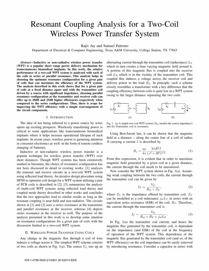
Any change in the magnetic flux through a coil of wireinduces a voltage across it. The simplest WPT scheme consistsof two coils as shown in Fig. 1(a). The source VG sets up an
alternating current through the transmitter coil (inductance) LT
which in turn creates a time varying magnetic field around it.A portion of this magnetic flux is coupled into the receivercoil LR which is in the vicinity of the transmitter coil. Thiscoupled flux induces a voltage across the receiver coil anddelivers power to the load RL. In principle, such a schemeclosely resembles a transformer with a key difference that thecoupling efficiency between coils is quite low in a WPT systemowing to the larger distance separating the two coils.
(a) (b)
Fig. 1. (a) A simple two-coil WPT system (RG models the source impedance)and (b) Transmitter coil in resonance.
Using Biot-Savart law, it can be shown that the magneticfield at a distance z along the centre line of a coil of radiusR carrying a current I is described by
Bz =µ0
4π
2πR2I
(z2 +R2)3/2(1)
From this expression, it is evident that in order to maximizemagnetic field generated by a given coil at a given distance,the current through the coil needs to be maximized.
Now consider the WPT system shown in Fig. 1(a). Assum-ing weak coupling between the two coils, the current throughthe transmitter coil can be given by
IT =VG
RG + ZT, (2)
where ZT is the impedance offered by transmitter coil. ZT
can be modelled as a coil inductance jωLT in series with anequivalent series resistance (ESR) of the coil, RT . Therefore,the current through the transmitter coil is
IT =VG
RG +RT + jωLT. (3)
In Fig. 1(a) the transmitter coil current, and hence themagnetic flux generated by the transmitter coil, is dependanton the impedance (and ESR) of the coil at the frequencyof operation of the WPT system. This dependence of themagnetic flux generated by the transmitter coil (and so, of theWPT efficiency) on the coil impedance can be easily removedby introducing resonance. Consider a capacitor in series with
978-1-4799-5924-2/14/$31.00 ©2014 IEEE

the transmitter coil as shown in Fig. 1(b). Then, the currentthrough the coil becomes
IT =VG
RG +RT + jωLT −j
ωCT
. (4)
Now, if the source frequency is chosen to be ω0 = 1√LTCT
,then the inductive and capacitive reactances cancel out, max-imizing the magnitude of current IT as
IT,max =VG
RG +RT; if ω0 =
1√LTCT
. (5)
This, in turn, maximizes the magnetic field generated by thecoil and hence the efficiency of coupling as well.
Having established the motivation to have the transmittercoil in resonance, the next logical step is to enquire ifresonance in the receiver coil can benefit the WPT system.Moreover, the possibility of employing a parallel resonance(capacitor in shunt with the coil) in place of the seriesresonance described above can be investigated. The aim of thefollowing analysis will be to determine whether one resonanceconfiguration is better than the other for a given pair of coils.
III. ANALYSIS OF COIL COUPLING IN A WPT SYSTEM
In the following subsections, a comparison of the WPTperformance with series and parallel resonances at transmitterand receiver coils is made. A coil is said to be in seriesresonance when the capacitor resonating with the coil is inseries with it. Similarly, for the coil to be in parallel resonance,the capacitor is in shunt with it. In a real WPT system, thetransmitter coil will see an additional load because of theload RL connected to the receiver coil. Thus the load the thereceiver is ”reflected” onto the transmitter coil. This reflectedload can be shown in series with the transmitter coil and socan be bracketed with RT shown in Fig. 2. In this analysis, asource VG driving the transmitter coil is considered to have asource impedance RG. Assuming QT to be the quality factorof the transmitter coil, the ESR of the transmitter coils isRT = QTωLT .
A. Series Versus Parallel Resonance at Transmitter
The transmitter coil can be configured with series or shuntcapacitors as shown in Fig. 2(a) and Fig. 2(b) respectively.From the previous section it was concluded that efficiency ofWPT can be maximized for a given transmitter coil and agiven distance of seperation between the coils by maximizingthe magnitude of alternating current through the coil.
In the series resonance configuration shown in Fig. 2(a),the current through the coil is given by (5) as derived in theprevious section. Now, if the transmitter coil was consideredto be high-Q, then the ESR of the coil will be very small andthe current through the coil can be approximated as
ITseries ≈VGRG
; if RG RT . (6)
To analyse the parallel resonance configuration shown inFig. 2(b), a narrowband impedance transformation can be
(a) (b)
(c)
Fig. 2. Transmitter coil in (a) series resonance and (b) parallel resonance. (c)depicts the circuit in (b) after narrowband impedance transformation.
applied as shown in Fig. 2(c). This transformation of thecircuit is justified since the source VG is driving the circuit atfrequency ω0. For this circuit, at resonance, the admittancesof the capacitance CT and the inductance LT together add upto zero. That means that the effective impedance seen by thedriver consists of just the resistance Q2
TRT . So at resonance,the voltage across this resistance Q2
TRT can be derived as
VT =Q2
TRT
RG +Q2TRT
VG ≈ VG; if RG Q2TRT . (7)
If the transmitter coil was considered to have very high-Q,then Q2
TRT will be much larger than the driver impedanceRG. Then the current through the coil can be written as
ITparallel =VTjω0L
≈ VGjω0L
; if RG Q2TRT (8)
From equations (6) and (8), it can be observed that theexpression for current through the coil at resonance is differentfor series and parallel resonance configurations. For a givenhigh-Q coil, if the source resistance RG is greater than thecoil impedance ω0L, then the magnitude of ITseries will besmaller than the magnitude of ITparallel and so the parallelconfiguration is preferred. On the other hand, if the sourceresistance RG is lower than the coil impedance ω0L, thenITseries will have a larger magnitude than ITparallel and usingseries configuration is more efficient for WPT.
Note that the assumption of a high-Q transmitter coilwas invoked in the above derivation. As typical biomedicalapplications employ a PCB transmitter coils which can providevery high Q, this assumption is justified. Generally, reflectedload seen at the transmitter coil due to the load RL at receivercan be approximated as k2 LT
LRRL [1]. Since the coupling
coefficient k 1, and assuming moderate to low load RL
at the receiver, this reflected load at the transmitter can beneglected.
B. Series Versus Parallel Resonance at Receiver
The two resonance configurations at the receiver coil iscompared in this section. The voltage that couples into thereceiver coil can be modelled as a voltage source VI in series

with the receiver coil. The following analysis compares thepower delivered to the load RL connected at the receivercoil for a given induced voltage VI at the receiver coil, forthe two configurations shown in Fig. 3(a) and Fig. 3(b). Theequivalent series resistance of the receiver coil is representedby the resistance RR in Fig. 3.
(a) (b) (c)
Fig. 3. Receiver coil in (a) series resonance and (b) parallel resonance. (c)depicts the circuit in (b) after narrowband impedance transformation.
Consider the series resonance configuration as shown in Fig.3(a). The current through the load RL is given by
ILseries =VI
RL +RR + jωLR −j
ωCR
(9a)
=⇒ ILseries =VI
RL +RR; if ω0 =
1√LRCR
. (9b)
Now, consider the parallel resonance configuration as shownin Fig. 3(b). At resonance frequency ω0, a quality factor QR
is defined asQR = ω0CRRL. (10)
QR helps transform the parallel impedances of RL and CR
shown in Fig. 3(b) to a series arrangement of RL,S andCR,S as shown in Fig. 3(c) through a narrowband impedancetransformation. The equivalent series capacitance CR,S andthe equivalent load resistance RL,S in Fig. 3(c) is related toCR and RL in Fig. 3(b) by
CR,S =Q2
R + 1
Q2R
CR, &RL,S =RL
Q2R + 1
. (11)
Note that the effective load seen by the coil has nowdecreased by a factor of Q2
R + 1 when compared to theseries resonance configuration. For this transformed circuit,the current through the equivalent load RL,S is
ILparallel =VI
RL,S +RR + jωLR −j
ωCR,S
, (12a)
=⇒ ILparallel =VI
RL,S +RR; if ω0 =
1√LRCR,S
. (12b)
Notice that the resonance frequency ω0 is not exactly thesame as the condition derived in (9b) for the series resonanceconfiguration. The resonance frequencies in these two casesare equal only if QR 1. But unlike the assumption madeon the quality factor QT of the transmitter coil, QR may notalways be greater than 1.
The power delivered to the load at resonance in the twoconfigurations are
Pseries = I2LseriesRL, & Pparallel = I2LparallelRL,S . (13)
Assuming the receiver coil to be high-Q (not to be confusedwith QR of considered in the derivation of ILparallel) then,the ESR of the receiver coil is much smaller than the load.That is, RR RL and RR RL,S . Under this condition,substituting for currents in expressions (13) from (9b) and(12b), the power delivered to the load in the two configurationsare
Pseries =V 2I
RL, & PParallel =
V 2I
RL,S. (14)
Since RL,S < RL, the power delivered will be more in theparallel resonance configuration.
Revisiting the expressions for load current in series andparallel resonances ((9a) and (12a)), it can be observed thatif the load resistances RL ωL, then there is no benefit ofhaving a capacitance cancel out the jωL term. This is becausethe magnitude of the load current is going to be dominated byRL. Typically, in any application, the load RL is usually arectifier circuit which can be modelled as a resistance anda capacitance in series. Hence even in the absence of anexplicit capacitance CR in Fig. 3(a), it is still possible to havecancellation of jωL term. It may be possible that the −j
ωCterm introduced by the rectifier load can dominate over jωLof the coil. In such a case, the WPT system is best servedby redesigning the coil such that jωL term matches −jωC atω = ω0.
In a typical application in biomedical implants, the receivercoil can be an on-chip integrated inductor. The Q of suchon-chip inductor is significantly lower than the Q of a PCBinductor. In this case, the optimum resonance configuration isdetermined by the relative values of RL,S , RL and RR.
IV. RESULTS
To explore the analysis made in the previous section, a WPTsystem involving a PCB coil transmitting power to an on-chip integrated coil was considered. Coil dimensions from [5],summarized in Table I, were utilized with a 5mm separation inair. The coil coupling was simulated using Ansys HFSS Elec-tromagnetic simulator and a two-port model obtained, whichwas then plugged into a circuit simulator (Cadence Virtuoso)to simulate the various resonance configurations discussed inthe previous section. Choosing the resonant frequency to be100MHz and based on the inductance of the coils extractedfrom HFSS simulations, the resonance capacitances CT andCR were chosen to be 204pF and 265pF respectively. Fig. 4shows the on-chip coil structure used in HFSS simulation.
The transmitting PCB coil was simulated to have a qualityfactor of close to 167 and gives the RT of around 50mΩ. Now,setting up the on-chip receiver coil with parallel resonance anda load RL = 1kΩ, and driving the transmitter through RG=100mΩ, it can be seen from the plots in Fig. 5(a) that series orparallel resonance gives about the same efficiency of around

(a) (b)
Fig. 4. (a) Integrated coil model used in HFSS. (b) shows the cross sectionof (a) along the dotted line.
TABLE ICOIL DIMENSIONS
PCB Coil On-Chip CoilTurns 1 2
Outer Diameter (mm) 14 2Trace Width (µm) 3500 140
Trace Spacing (µm) 500 200Substrate 1-oz FR-4 0.18µm CMOS
Inductance(nH) 12 9.4
-20dB at 100MHz. On the other hand, when transmitter coilis driven through an RG= 50Ω, it can be seen from the plotsin Fig. 5(b) that parallel resonance offers close to 25dB higherefficiency than series resonance at 100MHz, as predicted bythe analysis presented in the previous section.
(a) (b)
Fig. 5. Coupling efficiency with parallel resonance at receiver coil with RL=1kΩ when transmitter coil is driven through (a) RG = 100mΩ and (b)RG = 50Ω.
Since in any WPT system, the receiver coil generally drivesa rectifier, a simple gate-cross coupled rectifier was designedin 0.18 µm CMOS as shown in Fig. 6(a) and the resonanceconfigurations at the receiver coil was contrasted with thiscircuit driving 1kΩ as load. With the transmitter in parallelresonance configuration with RG = 50Ω, it can be seen fromthe plots in Fig. 6(b) that parallel resonance configurationat the receiver offers close to 20dB higher efficiency at100MHz when compared to series resonance configuration.This observation is also in concordance with the predictionsmade in the analysis presented in the previous section.
To validate the predictions in a real-world setting, a pair ofPCB coils described in Table I was manufactured and WPTefficiencies were measured using a network analyser (RG =RL = 50Ω) for cases involving series and parallel resonancesat transmitter and receiver coils. As shown in Fig. 7, in bothTX and RX coils, parallel resonance seems to offer close to10dB higher performance.
(a) (b)
Fig. 6. (a) Rectifier Circuit (b) Coupling efficiency with the receiver coildriving the rectifier.
(a) (b)
Fig. 7. Measurement results for (a) Series versus parallel resonance attransmitter with receiver coil in parallel resonance, and (b) Series versusparallel resonance at receiver with transmitter coil in parallel resonance.
V. CONCLUSION
Various combinations of resonance configurations can beemployed in a inductive WPT system with two coils. Theanalysis has shown that in a system with a high-Q transmittercoil driven by a source with significant source impedance, aparallel resonance configuration is preferred at the transmittercoil. Moreover, for a typical system, parallel resonance seemsto be more efficient at the receiver coil as well. With the rightconfiguration, the efficiency of WPT can improve by as muchas 20dB. Though the analysis neglected the loading seen bythe transmitter coil due to the receiver, the trend predicted bythe analysis has been validated with laboratory measurementson PCB based WPT system.
REFERENCES
[1] R. Harrison, “Designing efficient inductive power links for implantabledevices,” in Proceedings IEEE International Symposium on Circuits andSystems, May 2007, pp. 2080–2083.
[2] U.-M. Jow and M. Ghovanloo, “Design and optimization of printed spiralcoils for efficient transcutaneous inductive power transmission,” IEEETransactions on Biomedical Circuits and Systems, vol. 1, no. 3, pp. 193–202, Sept 2007.
[3] M. Kiani and M. Ghovanloo, “The circuit theory behind coupled-modemagnetic resonance-based wireless power transmission,” IEEE Transac-tions on Circuits and Systems I: Regular Papers, vol. 59, no. 9, pp. 2065–2074, Sept 2012.
[4] A. RamRakhyani, S. Mirabbasi, and M. Chiao, “Design and optimizationof resonance-based efficient wireless power delivery systems for biomed-ical implants,” IEEE Transactions on Biomedical Circuits and Systems,vol. 5, no. 1, pp. 48–63, Feb 2011.
[5] M. Zargham and P. Gulak, “Maximum achievable efficiency in near-field coupled power-transfer systems,” IEEE Transactions on BiomedicalCircuits and Systems, vol. 6, no. 3, pp. 228–245, June 2012.