response of a taipei rapid transit system (trts) tunnel to
TRANSCRIPT
1
Response of a Taipei Rapid Transit System (TRTS) tunnel to
adjacent excavation
Chi-Te Chang1, Chieh-Wen Sun1, S. W. Duann2 and Richard N. Hwang2
1 Central District Office, Department of Rapid Transit System, Taipei City Government, Taipei,
Taiwan
2 Moh and Associates Inc., Taipei, Taiwan
Corresponding author
Chi-Te Chang
Central District Office
Department of Rapid Transit System
Taipei City Government
Taipei, Taiwan
Tel: 886 2 2521 5550
Fax: 886 2 2511 5335
Email: [email protected]
ABSTRACT
During the construction of the Taipei Rapid Transit System (TRTS) tunnels, a section of
tunnel in the Panchiao Line was damaged as a result of adjacent excavation. Cracks
appeared in reinforced concrete segments, the concrete slab on the invert was displaced
and detached from the segments. The event is a valuable case history for establishing
criteria regulating excavations to be carried out adjacent to existing tunnels.
KEYWORDS: shield tunneling, monitoring, deep Excavation, damage

2
1. INTRODUCTION
Subsequent to the completion of a section of the Panchiao Line tunnels of the Taipei
Rapid Transit System (TRTS) in November 1995, excavation was carried out, to the
east of the tunnels for a highrise building with a 5-level deep basement. The plan and
section of the excavation site adjacent to the tunnels are shown in Figs. 1 and 2. To
safeguard these tunnels, ground response was closely monitored by using inclinometers.
Furthermore, instruments were installed on tunnel segments to measure the stresses and
strains induced. Readings of these instruments indicated significant movements of the
up-track tunnel and failure of structural members due to the excavation. Cracks were
observed in the segments. The concrete slab on the invert was dislocated and became
detached from the segments due to distortion of the tunnel linings. The down-track
tunnel, however, was not affected.
2. GROUND CONDITIONS
As shown in Fig. 2, the subsoils at the site consist of a sequence of alternating silty clay
(CL) and silty sand (SM). Underlying these clay and sand layers is a thick layer of
gravels (GM) which is extremely permeable and is very rich in water reserve. Because
of excessive pumping for drawing water from this underlying gravelly layer in the past,
the hydraulic pressures in the overlying subsoils were once much lower than their
current levels. Therefore, the silty clays were mildly over-consolidated with Su values
generally increase from 15 to 40 kPa with depth. The SPT N-values in the silty sands
generally vary from 10 to 40.
3. The TRTS TUNNELS
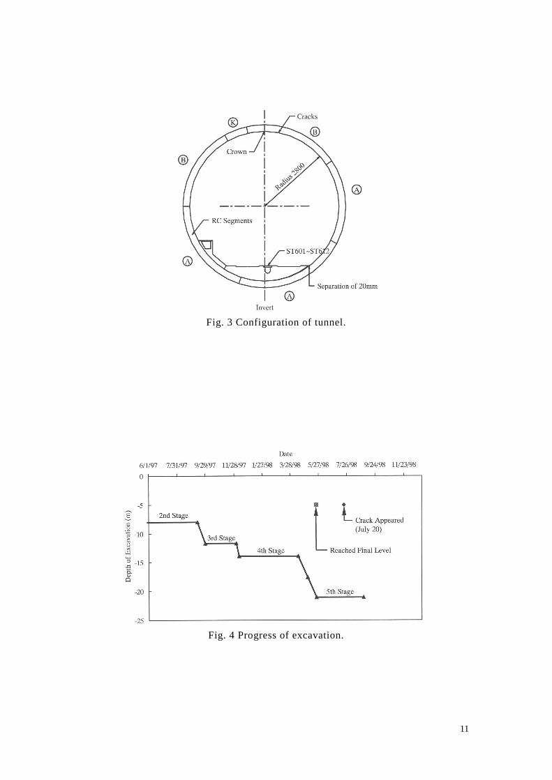
As shown in Fig. 3, the two tunnels have an internal diameter of 5.6m and are lined by
reinforced concrete segments of 250mm thick and 1m wide. Segments are bolted
together by curved bolts.
The tunnels were bored by using an earthpressure balancing (EPB) shield tunneling
machine of 6240mm in outer diameter. The machine was launched from the shaft
located at the southern end of the up-track tunnel and made a u-turn at the shaft located
at the other end for boring the down-track tunnel. The shell of the machine was

3
abandoned in the down-track tunnel upon the completion of the tunneling in November
1995. Subsequently, reinforced concrete slabs were cast on the inverts of the two
tunnels and rails were laid.
4. ADJACENT EXCAVATION
The excavation for constructing the highrise building to the east of the tunnels was
commenced 9 months later in August 1996. The building has a 5-level basement and
excavation, as shown in Fig. 2. The excavation was carried out to a depth of 21.1m.
The excavation opening was supported by diaphragm walls which extended to a depth
of 36m below surface. Concurrent with the main excavation, a passageway was
constructed to connect this building to the TRTS station located south of the tunnels.
The western wall of the passageway was retained by a row of bored piles of 600mm in
diameter and 13m in length. To enable this passageway to be excavated together with
the deep basement at the same time, the top 7.6m of the diaphragm wall between the
two was left un-cast.
To reduce the lateral movements of the retaining wall close to the tunnels, ground
improvement was carried out in an area of 46.5m in length and 21m in width. High
pressure jet grouting was carried out in 23 rows with a typical spacing of 2.2m, center to
center, and was carried out to a depth of 5m below the base of the excavation prior to
the commencement of excavation.
Excavation started in August 1996 and reached its final depth in late May 1998. The
excavation program is shown in Fig. 4. The excavation was braced by 5 levels of struts
which were preloaded to reduce wall movements, as shown in Fig. 2.
5. OBSERVATIONS
In the area shown in Fig.1, there were 6 inclinometers (SIS603~SIS608) alongside the
up-track tunnel for monitoring the ground response near the tunnel and 2 inclinometer
(SIS611~SIS612) immediately next to the diaphragm wall of the adjacent deep
excavation for monitoring wall movements. Inside the up-track tunnel, there were 12
survey points (ST601~ST612) mounted at the center of the concrete slab (Fig. 3) and 12
telltales mounted across joints between segments. Furthermore, the movements of the
tunnel were measured by wriggle survey and the deformations of rings were monitored

4
by configuration survey.
In July 1998, it was observed that a portion of the concrete slab running from Ring No.
6 to Ring No. 70 in the up-track tunnel was detached from the tunnel segments leaving
gaps of up to 20mm. Cracks were also observed at the tunnel crown in a 38m stretch
running from Ring No. 11 to Ring No. 49. The widths of cracks varied from 0.05mm to
0.25mm. Furthermore, there was an offset of 10mm between Ring No. 24 and Ring No.
25 at the crown. The down-track tunnel, however, was unaffected.
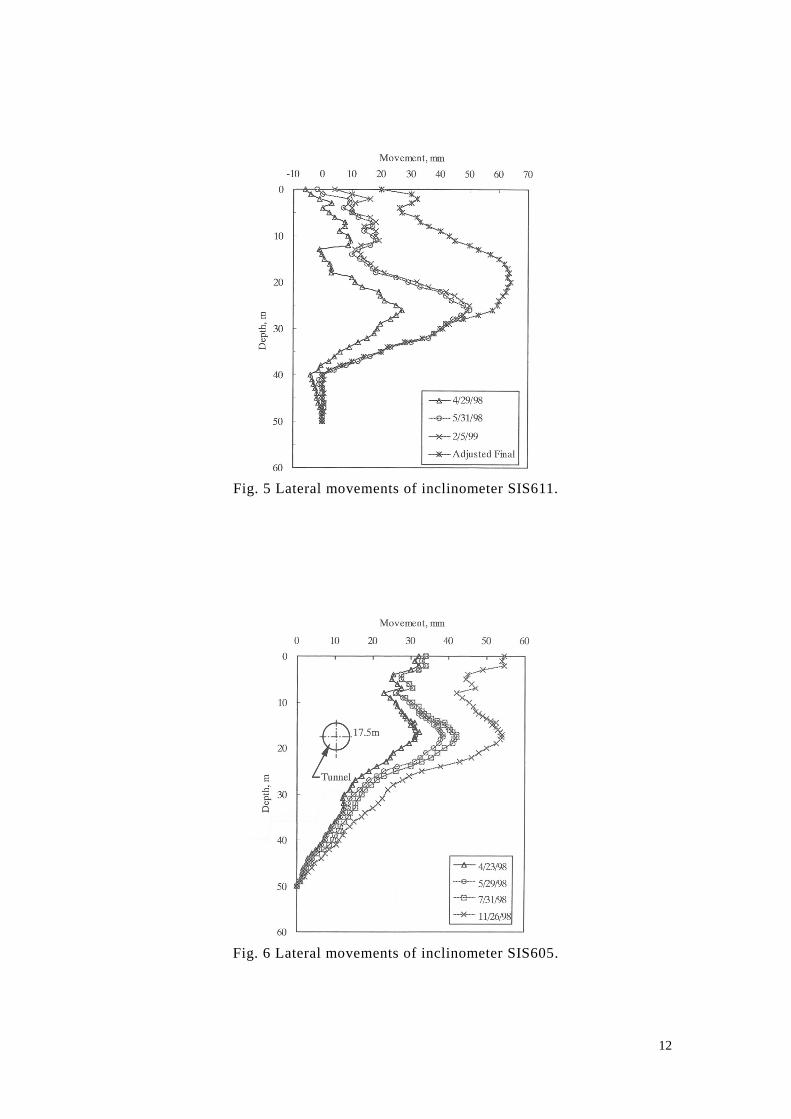
5.1 Lateral Ground Movements
Fig. 5 shows the readings of Inclinometer SIS611 at various dates. This inclinometer
was very close to the diaphragm wall and the readings obtained are thus more-or-less
representative of the wall movements. As can be noted from the readings that much
lateral movement were induced in May 1998 in which the last stage of excavation was
carried out. Subsequently, the wall appeared to be stable and very little movements
were observed till the end of construction as evidenced by the small difference between
the readings obtained on 2/5/99 and those obtained on 5/31/98.
A maximum wall displacement of 53mm was recorded by SIS611 at the end. It
however should be noted that this inclinometer was installed in June 1997 when
excavation had already reached a depth of 8m. Furthermore, the abrupt reduction in
lateral movements of 20 to 30mm at depths of 12m to 19m was caused by grouting
carried out in November 1997 to seal off leakage at joints between diaphragm wall
panels. The profile denoted as “Adjusted Final” in the figure includes the following
modifications to the readings:
a. Adding the wall displacements induced prior to the installation of the inclinometer
as calculated by using the computer program RIDO
b. Removing the effects of grouting by judgment
With these modifications, the maximum wall displacement is estimated to be about
63mm.
Figure 6 shows the readings of inclinometer SIS605, which was very close to the
eastern edge of the up-track tunnel. As can be noted that a maximum lateral movement
of 54mm was recorded at a depth of 17.5m which incidentally corresponds to the depth
of the center of the tunnel. It can also be noted from the figure, by comparing the data

5
obtained on 7/31/98 with those obtained on 11/26/98, the lateral movements of the
ground at this location were significantly large, two months after the excavation had
reached its final level and the diaphragm wall had become stable.
The readings obtained at the depth corresponding to the center of the tunnel are shown
in Fig. 7. It can be noted that the lateral movement of this inclinometer was about
37mm when the excavation reached its final level in late May. It then increased to
44mm in late July. At the same time, cracks in segments were observed.
5.2 Movements of Tunnel
The lateral movements of the up-track tunnel were obtained by wriggle survey and the
results are compared with inclinometer readings in Fig. 8. The data points for the
centers of rings, as expected, fall between those for the inclinometers on the two sides
of the tunnel. The 19mm difference in movement between Ring No. 24 and Ring No. 25
is qualitatively compatible with the observation that the two rings had an offset of
10mm or so at the crown. The movements of other segments appear to be consistent
with the “idealized movements profile” shown in Fig. 8.
As indicated in the lower part of Fig. 8, the vertical movements of the tunnel varied
from 20mm to 33mm for the segments measured. These movements had little to do
with the lowering of groundwater table because it has been found that groundwater
table was stable during the period of excavation. A small fraction of these movements
could be attributed to the earth filling work carried out on ground surface. This,
however, is beyond the scope of this paper.
Shown in Fig. 9 are the convergences of linings in the up-track tunnel obtained by
configuration survey. Ring No. 24, which appears to be the most affected, was
shortened by 45mm in the vertical direction and elongated by 26mm in the horizontal
direction. In theory, the squashing of the tunnel would increase the lateral movements
of inclinometers on the eastern side of the tunnel and reduce the lateral movement of
inclinometers on the western side. For this reason, refer to Fig. 8, the lateral movement
of SIS606 was westward instead of eastward.
There were 12 telltales to measure the widening of joints between segments. All of
them showed sudden changes, up to 1mm, on 20 July 1998. It definitely have
something to do with the detachment of the concrete slab with the segments. The
possibility that some of the structural elements failed cannot be ruled out.
6
5.3 Movement of Slab
Lateral movements of the concrete slab at the invert of the tunnel were measured at 12
locations, i.e., ST601~ST612, and the readings are shown in Fig. 10. The movement
ranged from 13mm to 18mm for the segments measured and were fairly uniform. This
range is qualitatively comparable with the lateral movements of the center of the tunnel
shown in Fig. 8, except for two of the rings, Rings No. 24 and 35 of which the
movements were comparatively large. It is reasonable for the slab to have smaller
movements than the tunnel center because the slab is three meters below the tunnel
center, where the lateral ground movements were the greatest (as shown in Fig. 6).
Furthermore, the slab was detached from the segments leaving gaps of roughly 20mm
between the two.
The readings of ST609 are plotted for a period of about 18 months from June 1997 to
November 1998 in Fig. 11. It appears that the movements of the slab were negligible
till 20 July. Then, the slab suddenly moved by 10mm or so. This phenomenon is rather
inconsistent with the inclinometer readings (Figs. 6 and 7) which showed continuing
movements over the several months prior to July and afterward. It is highly unlikely for
the slab to become detached from the tunnel segments in the early phase of excavation.
Therefore, it is unsure whether the tunnel indeed moved with the inclinometer all the
time. Unfortunately, there is only one set of wriggle survey and the history of
movement of the tunnel cannot be traced.
The vertical movements of the slab were also monitored and the readings are shown in
Fig. 10. Contrary to the tunnel centers, the readings showed heaves of the slab at all
these locations. A maximum heave of 15mm was observed at the location of Ring No.
26. The heaves at this location are plotted in Fig. 11. Judged by the fact that a sudden
lateral movement occurred on 20 July 1998, it is believed that the vertical movements
also occurred suddenly on that day.
6. DISCUSSIONS
Safety of tunnel as affected by adjacent excavation activities has been a primary
concern and various regulatory agencies have attempted to establish criteria to restrict
ground movements to be induced (Shirlaw et al 2000, Doran et al 2000). Because of the
lack of case histories on damages to tunnels, most of the criteria adopted were more or

7
less arbitrary (Richards 1998).
6.1 Performance of Tunnel
It would be of interest to investigate how much movement this tunnel can tolerate
without structural damages. Although failure appears to occur on 20 July 1998, signs of
distress were noticed in segments in February 1998. The idealized movement profile
shown in Fig. 8 are the deviations of the center of the tunnel from the original alignment
and the maximum deviation was estimated to be 27mm. Data are insufficient for
determining what the movements were in February 1998. As shown by the
measurements in Figs. 6 and 7, the ground continued to move after February 1998.
However, it is unsure whether the tunnel followed the ground. With considerable
judgment, it is assumed that the movements of the tunnel center in February 1998 were
70% of the idealized movements shown in Fig. 8. The maximum movement is then
estimated to be of an order of 20mm in February 1998 and this magnitude may be
considered as the allowable movement of this tunnel. It is fully understood that
maximum movement is not a governing factor in evaluating the safety of tunnels. It is
the curvature of the movement profile that matters. However, from a practical point of
view, maximum movement is certainly an important index in evaluation of the safety of
a tunnel.
It should be noted that since tunnels behave as beams, the damage potential would
depend on their alignments in relation to the directions of ground movements. If a
tunnel bulges toward the excavation as is the case presented here, it is more susceptible
to damages because the tunnel will be lengthened as the ground moves and the joints
tend to open up. If it bulges away from the excavation, it is less susceptible to damages
because the joints tend to close up due to arching effects.
It is understood that vertical movements are equally important in the evaluation of
safety of tunnels. Similarly, a tunnel with a sagging profile is more susceptible to
damages and a tunnel with a hogging profile is less susceptible.
The performance of the up-track tunnel was affected by the adjacent excavation and
repair work was subsequently carried out (Chang et al 2001).

8
6.2 Monitoring of Performance of Tunnel
Based on the data presented, it is clear that inclinometer readings are not representative
of the movement of the tunnel. Squashing of tunnel lining should be considered if
inclinometers are used to monitor the performance of a tunnel. In the case discussed
here, an allowance of 10 to 20mm shall be added to or subtracted from, depending on
which side of the tunnel the inclinometer is installed, the inclinometer readings to
obtain the movements of the center of tunnel.
6.3 Soil-Tunnel Interaction
The excessive movements of Rings No. 24 and 35 suggest that the tunnel behaved as a
beam resisting ground movements until it could no long hold. The large differences
between the movements of the tunnel and the movements of the ground are rather
surprising because it has been expected that long tunnels with thin segments tightened
by curved bolts would offer little resistance to ground movements. In the case studied,
the concrete slab at the invert must have significantly increased the rigidity of the
tunnel. The rigidity of the tunnel greatly exceeds the rigidity of the surrounding soils.
When the potential risk is assessed prior to excavation, ground response is normally
analyzed without considering the presence of tunnel. Since tunnels behaved as beams
which will reduce ground movements in soft ground, it is necessary to take this effect
into consideration to achieve a more comprehensive assessment.
7. CONCLUSIONS
Based on the data presented, the following is concluded:
1. The movement which can be tolerated by a tunnel will depend on the shape of
tunnel alignment.
2. Inclinometer readings are not representative of movements of a tunnel and
adjustments shall be made to account for the squahing of tunnel lining.
3. Tunnels behave as beams and will reduce ground movements induced by adjacent
excavation and ground engineering activities.
Although the case presented in this paper is an isolated one, it nevertheless suggests that

9
shield tunnels with a similar design are vulnerable to ground movements of small
magnitudes.
ACKNOWLEDGMENT
Most of the data presented herein were obtained from a report prepared be Sinotech
Engineering Consultants, Ltd. For that, the authors are sincerely grateful. The authors
are also grateful to the contractor for the rapid transit project and the contractor for the
adjacent development for their assistance in providing detailed instrument readings.
REFERENCES
Chang C-T, Wang M-J, Chang C-T and Sun C-W, (2001), Repair of a displaced shield
tunnel of the Taipei Rapid Transit System. Tunnelling and Underground Space
Technology, Vol.16(3), pp.???-???..
Doran, S.R., Wood, T., Tham, S.K., Copsey, J.P., Shirlaw, J.N. and Wen, D., (2000),
The assessment of limits for the movement of subway tunnels and trackwork due to
adjacent construction. Tunnels and Underground Structures, edited by Zhao J., Shirlaw,
J.N. and Krishnan, R., Balkeme, Rotterdam, pp.495-500.
Richards, J.A., (1998), Inspection, maintenance and repair of tunnels: international
lessons and practice. Tunnelling and Underground Space Technology, Vol.13(4),
pp.369-375.
Shirlaw, J.N., Tham-Lee, S.K., Wong, F.K., Ang-Wong, L.P., Chen, D.C., Osborbe, N.
and Tan, C.G., (2000), Planning the monitoring required to confirm the movement and
rotation of tunnels and trackwork due to excavation and tunneling. Tunnels and
Underground Structures, edited by Zhao J., Shirlaw, J.N. and Krishnan, R., Balkeme,
Rotterdam, pp.489-494.
Sinotech, (1999), Effects of Adjacent Construction to Existing TRTS Tunnel, October,
1999.

10
Fig. 1 Site plan.
Fig. 2 Section A-A.
11
Fig. 3 Configuration of tunnel.
Fig. 4 Progress of excavation.
12
Fig. 5 Lateral movements of inclinometer SIS611.
Fig. 6 Lateral movements of inclinometer SIS605.

13
Fig. 7 Lateral movements of inclinometer SIS605 at depth of tunnel center.
Fig. 8 Movements of the center of the Up-Track Tunnel (December 1998).
Fig. 9 Convergence of lining of the Up-Track Tunnel (December 1998).

14
Fig. 10 Movements of the concrete slab (December 1998).
Fig. 11 Movements of the concrete slab.