rev. d instructions for installation, operation care...
TRANSCRIPT

Model HDouble InterlockPreaction System11
2� (40mm)
Bulletin 720 Rev.DB
ulle
tin7
20
Re
v.D
Instructions forInstallation, OperationCare and Maintenance10 PSI (0,7 bar) Pneumatic Supervising PressureWith Electric Pneumatic Actuation, Type D
The Reliable Automatic Sprinkler Co., Inc., 103 Fairview Park Drive, Elmsford, New York 10523

General DescriptionReliable Preaction Systems are designed for water
sensitive areas which require protection from inadver-tent water flow into the sprinkler system piping.
The major benefits of a preaction system, when com-pared with a wet pipe system, are summarized as fol-lows:
A. A fire alarm sounds with activation of a detector andprior to the operation of a sprinkler, which may en-able extinguishing the fire by handheld means be-fore the operation of any sprinkler head occurs.
B. An alarm condition occurs whenever the integrity ofpiping or sprinklers is accidentally or intentionallydisturbed; however, no water flow or water damagewill result at that time.
C. Speedy detection with an early fire alarm is pro-vided by fire detectors, without the delay associ-ated with water delivery time in a wet pipe system inthe event of a fire. Note that with a wet pipe system,the fire alarm is delayed until after water has begunflowing from an operated sprinkler head.
To flow water into an electric pneumatic double inter-lock preaction system, two events must take place. Afire detection device must operate, and a low pressureswitch must be operated by the loss of system pressure(sprinkler operation). These two signals must coexist atthe releasing control panel which only then will energizethe solenoid releasing valve, causing water flow into thesystem and out of the open sprinkler(s).
This bulletin describes a Reliable Double InterlockType D Preaction System which utilizes the ReliableModel H 1½� (40mm) Deluge Riser Assembly. Thisdouble interlock system uses fire detection devices andsystem supervisory pressure as two separate zones(inputs) to a cross-zoned Potter PFC-4410-RC Releas-ing/Control Panel. The system is pressurized (super-vised) with air or nitrogen and monitored by the lowpressure switch. The solenoid releasing valve remainsclosed until energized by the releasing control panel.This will occur only when both a fire detection devicehas operated and the low pressure switch has detectedsufficient loss of system supervising pressure (sprinkleroperation).
In the event that the system piping is ruptured or asprinkler head is accidentally opened, the low pressureswitch will operate and an alarm will sound. The riserassembly however, will not release water since the sole-noid valve remains closed due to only one input into thecross-zoned control panel.
In the event that a fire detection device is falsely oper-ated, the control panel will activate an alarm. The riserassembly, however, will not release water since the sole-noid valve remains closed due to only one input into thecross-zoned control panel.
2.
The requirement for simultaneous inputs from both adetector and the loss of supervising pressure before theriser assembly releases water into a preaction systemassures maximum protection against inadvertent waterflow before a sprinkler is open. Double interlock sys-tems are primarily used to protect refrigerated areaswhere accidental water release before a sprinkler isopened can cause ice blockage, resulting in an inop-erative sprinkler system and substantial property dam-age.
A hydraulic manual emergency releasing station isstandard equipment in the Model H Riser Assembly. Itis identified by a nameplate attached above thereleasing valve.
A preaction trim kit is available to provide a bypassdrain line and to attach the air or nitrogen supply re-quired to supervise the preaction system. This kit in-cludes a UL Listed Reliable Model G Right Check™Valve supplied with rigid grooved pipe couplings, as il-lustrated in Figure 4. To produce a Double Interlockpreaction system, the switch/gauge trim kit illustrated inFigure 5 must be added.
ApprovalsThe 1½� Model H Riser Assembly is Underwriters
Laboratories, Inc. Listed in the Special System WaterControl Valves Deluge Type (VLFT) category. It is alsolisted by Underwriters’ Laboratory of Canada. TheModel G Right Check™ Valve is listed by UL and ULC.NYC MEA 258-93-E applies to both the Model H RiserAssembly and the Model G Right Check™ Valve.
Technical DataThe 1½� (40mm) Reliable Double Interlock Peaction
System is rated for a minimum supply pressure of 20 psi(1,4 bar) and a maximum supply pressure of 175 psi (12bar).
Friction loss, expressed in equivalent length of Sch.40 pipe and based on Hazen-Williams formula withC=120, and a flowing velocity of 15 ft./sec (4.6 m/s), is29 ft (8.84m) for the Model H Riser Assembly, and 7 ft.(2.1m) for the 2½� (65mm) Model G Right Check�
Valve.
Shipping Weights:
Model H Riser Assembly 52 lbs (23.6 kg)
Model A-2 Press. Maint. Dev. 9 lbs ( 4.0 kg)
Preaction Trim Kit 18 lbs ( 8.2 kg)
Pressure Switch/Gauge Kit 5 lbs ( 2.3 kg)
Model 1LAA-11T-M100X
Tank Mounted Compressor 49 lbs (22.2 kg)
The following list of bulletins describe componentswhich are used with this system:
Deluge Riser Assembly 507Water Flow Pressure Alarm Switch A05-0176(System Sensor)Pressure Maintenance Device 251Air Compressor (Tank Mounted) 700Releasing/Control Panel Potter #5403550Electric Emergency Station 700Thermal Detectors 722Fire Alarm Devices 700Automatic Nitrogen Reg. Device 253Model G Right Check™ Valve 806
System Design ConsiderationsThe automatic sprinklers, air compressor, releasing
devices, electric releasing control panel, fire detectiondevices, manual pull stations, and signaling deviceswhich are utilized with the Systems must be UL and/orULC Listed, as applicable.
The Reliable Double Interlock Preaction Riser equip-ment (Figure 6) and all interconnecting piping must belocated in a readily visible and accessible location and inan area which can be maintained at a minimum temper-ature of 40°F (4°C).NOTE: HEAT TRACING IS NOT PERMITTED.
The solenoid valve is operated and supervised by theelectric releasing control panel. Details on connectingthe electrical portion of this system to a Releasing/Con-trol Panel can by found in Reliable Bulletin 700.
Hydrostatic Testing of SystemsAs required by NFPA 13, fire sprinkler systems with
working pressures up to and including 150 psi are to behydrostatically tested at a water pressure of 200 psi andmaintain that pressure without loss for two hours. Firesprinkler systems with working pressures above 150 psiare required to be hydrostatically tested at 50 psi abovethe system working pressure and maintain that pressurewithout loss for two hours. In addition to the hydrostatictests described above, dry pipe and double interlockpreaction systems require an additional low pressure airtest.
In some cases, hydrostatic testing (in accordancewith the NFPA 13 requirements noted above) will result inpressures that exceed the working pressure of the valveand trim kit for the two-hour test period. The valve andapplicable trim kit have been tested, approved andlisted under these conditions and as such, hydrostatictesting in accordance with NFPA 13 is acceptable. Inaddition, the clapper can remain in the closed positionand the trim kit need not be isolated, as each has beendesigned to withstand hydrostatic testing as required byNFPA 13.
3.
Hydrostatically testing the valve and trim to pressureshigher than their rating is limited to the hydrostatic testas referenced by NFPA 13. It does not address the oc-currence(s) of a “water hammer” effect, which can in-deed damage the valve. A “water hammer” in the watersupply piping of the valve can create pressures in ex-cess of the rated pressure and should be avoided by allnecessary means. This condition may be created fromimproper fire pump settings, underground constructionwork, or an improper venting of trapped air in the watersupply piping.
System Air Pressure RequirementsIn accordance with NFPA 13 (1996), the Reliable
Double Interlock Type D Preaction System requires aminimum of 7 psi (0,5 bar) pneumatic pressure to su-pervise the sprinkler system. The Model A-2 PressureMaintenance Device is used to maintain system pneu-matic pressure at approximately 10 psi (0,7 bar). TheModel A-2 Pressure Maintenance Device controls su-pervisory pressure where a dry nitrogen gas supply or aclean, dependable and continuous (24 hours per day, 7days per week) compressed air source is available.
Adjusting system pressure to approximately 10 psi(0,7 bar) is accomplished by referring to Reliable Bulle-tin 251 for adjustment procedure. The low pneumaticpressure supervisory switch (Item 5, Figure 5) is factoryset to operate between 8 and 4 psi (0,55 and 0,28 bar)with decreasing pressure. Adjustment, if required,should be made according to Bulletin A05-0176 in-cluded with the switch.
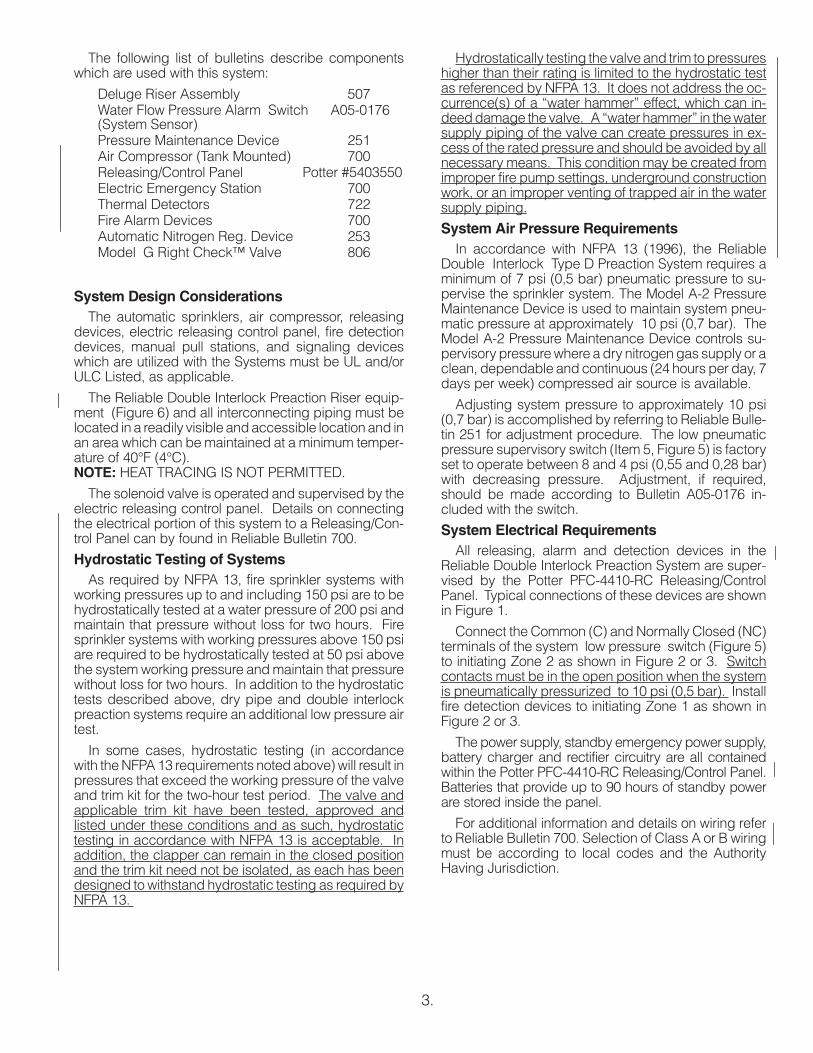
System Electrical RequirementsAll releasing, alarm and detection devices in the
Reliable Double Interlock Preaction System are super-vised by the Potter PFC-4410-RC Releasing/ControlPanel. Typical connections of these devices are shownin Figure 1.
Connect the Common (C) and Normally Closed (NC)terminals of the system low pressure switch (Figure 5)to initiating Zone 2 as shown in Figure 2 or 3. Switchcontacts must be in the open position when the systemis pneumatically pressurized to 10 psi (0,5 bar). Installfire detection devices to initiating Zone 1 as shown inFigure 2 or 3.
The power supply, standby emergency power supply,battery charger and rectifier circuitry are all containedwithin the Potter PFC-4410-RC Releasing/Control Panel.Batteries that provide up to 90 hours of standby powerare stored inside the panel.
For additional information and details on wiring referto Reliable Bulletin 700. Selection of Class A or B wiringmust be according to local codes and the AuthorityHaving Jurisdiction.
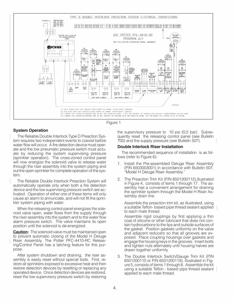
Figure 1
System OperationThe Reliable Double Interlock Type D Preaction Sys-
tem requires two independent events to coexist beforewater flow will occur. A fire detection device must oper-ate and the low pneumatic pressure switch must actu-ate by reducing the system supervising pressure(sprinkler operation). The cross-zoned control panelwill now energize the solenoid valve to release waterthrough the riser assembly into the system piping andout the open sprinkler for complete operation of the sys-tem.
The Reliable Double Interlock Preaction System willautomatically operate only when both a fire detectiondevice and the low supervising pressure switch are ac-tivated. Operation of either one of these items will onlycause an alarm to annunciate, and will not fill the sprin-kler system piping with water.
When the releasing control panel energizes the sole-noid valve open, water flows from the supply throughthe riser assembly into the system and to the water flowalarm pressure switch. The valve maintains its openposition until the solenoid is de-energized.
Caution: The solenoid valve must be maintained opento prevent automatic closing of the Model H DelugeRiser Assembly. The Potter PFC-4410-RC Releas-ing/Control Panel has a latching feature for this pur-pose.
After system shutdown and draining, the riser as-sembly is easily reset without special tools. First, re-store all sprinklers exposed to excessive heat and thenrestore detection devices by resetting or replacing anyoperated device. Once detection devices are restored,reset the low supervisory pressure switch by restoring
4.
the supervisory pressure to 10 psi (0,5 bar). Subse-quently reset the releasing control panel (see Bulletin700) and the supply pressure (see Bulletin 507).
Double Interlock Riser InstallationThe recommended sequence of installation is as fol-
lows (refer to Figure 6):
1. Install the Pre-assembled Deluge Riser Assembly(P/N 6503003001) in accordance with Bulletin 507,“Model H Deluge Riser Assembly.”
2. The Preaction Trim Kit (P/N 6501200112),illustratedin Figure 4, consists of items 1 through 17. The as-sembly has a convenient arrangement for drainingthe sprinkler system through the Model H Riser As-sembly drain line.
Assemble the preaction trim kit, as illustrated, usinga suitable Teflon- based pipe thread sealant appliedto each male thread.
Assemble rigid couplings by first applying a thincoat of silicone or other lubricant that does not con-tain hydrocarbons to the lips and outside surfaces ofthe gasket. Position gaskets uniformly on the valveand adjacent reducers so that all grooves are ex-posed. Place coupling housings over gaskets andengage the housing keys in the grooves. Insert boltsand tighten nuts alternately until housing halves aredrawn together uniformly.
3. The Double Interlock Switch/Gauge Trim Kit (P/N6501200110 or P/N 6501200119), illustrated in Fig-ure 5, consists of items 1 through 6. Assemble the kitusing a suitable Teflon - based pipe thread sealantapplied to each male thread.

Class A WiringFigure 2 Class B Wiring
Verify that the check valve orientation is accordingto the directional flow arrow illustrated.
Install the pressure gauge included with this trim kitinto the Model A-2 Pressure Maintenance Deviceafter removing the ¼� NPT (R¼) plug, as illustratedin Figure 6.
The pressure switch is factory adjusted for opera-tion between 8 to 4 psi (0,55 to 0,28 bar). If field ad-justment is required or the lowest possible setting (4psi or 0,28 bar) is desired, refer to Figure 5 and pro-ceed as follows:
5.
Consult the enclosed switch manufacturer’s lit-erature (Bulletin A05-0176) for more detailed in-formation.
4. Install the Pre-assembled Model A-2 Pressure Main-tenance Device (P/N 6304000100) with pressuregauge in place, onto the Switch/Gauge Trim Kit as il-lustrated in Figure 6. Adjust the output pressure toapproximately 10 psi (0,7 bar) according to the in-structions in Bulletin 251, included.
5. When a dedicated pneumatic pressure supply is re-quired, a small tank mounted air compressor [suchas the 1
6 hp, 2 gal. (7.6 liters) Gast Model1LAA-11T-M100X illustrated in Figure 6] can be usedto input the Model A-2 Device.
Ifmoistureandpossible iceblockage is of concern, adry nitrogen gas cylinder with the Nitrogen Regulat-ing Device described in Bulletin 253,and illustratedin Figure 6, can be used to supply the Model A-2Device.
MaintenanceReliable Double Interlock Preaction Systems and as-
sociated equipment shall periodically be given a thor-ough inspection and test. NFPA 25, Inspection, Testingand Maintenance of Water Based Fire Protection Sys-tems, provides minimum maintenance requirements.Systems should be tested, operated, cleaned and in-spected at least annually, and parts replaced as re-quired. Refer to Bulletin 507 for information regardingmaintenance of the solenoid valve and the manualemergency station valve. Bulletin 251 provides infor-mation on the Model A-2 Pressure Maintenance De-vice. Bulletin 253 describes the automatic NitrogenRegulating Device.
Resetting Double Interlock SystemsRefer to Figure 6.
1. Close the supervised valve controlling water supply tothe riser assembly and shut off the system air/nitrogensupply at the Model A-2 Pressure Maintenance De-vice.
2. Open all drain valves and the manual emergency sta-tion valve to drain the system.
3. Open all drain valves and vents at low points through-out the system, closing them when flow of water todrain has stopped.
4. Inspectandreplaceanyportionof thesprinklersystemand detection system exposed to fire conditions. Re-set detectors (refer to Bulletin 700).Note: It is not possible to reset the PotterPFC-4410-RC Releasing/Control Panel (which is in thecross-zoned mode) until Step “6”, which resets the lowsupervising pressure switch, has been completed.
5. Restore the system supervising pressure to approxi-mately 10 psi (0,7 bar) by opening the valves on theModel A-2 Pressure Maintenance Device (refer to Bul-letin 251) and adjusting the regulator, as required.
6. Verify that the by-pass drain valve is closed to preventthe loss of pneumatic supervising pressure out of theautomatic drain valve. When the supervising pressurehas reached the 10 psi (0,7 bar) setting, the low super-vising pressure switch will automatically reset (con-tacts now open).
7. With the supervising pressure switch reset (Step “6”)andalldetectors replacedor reset (Step“4”), thePotterPFC-4410-RC Releasing/Control Panel can be reset.Pushing the “System Reset” switch in the panel will si-multaneously restore the solenoid valve to the closedcondition.
8. Restore water supply to the riser assembly in accor-dance with Bulletin 507, “Model H Deluge Riser As-sembly Instructions for Installation, Operation, Careand Maintenance.”
• Remove cover using wrench provided.
• Loosen locking screw until adjustment wheelrotates freely.
• Rotate adjustment wheel clockwise to end ofadjustment for lowest setting possible.
• Re-tighten locking screw to initial conditions.
• Replace cover.
Switch contact ratings are:
10A, ½ HP @ 125/250 VAC
2.5A, @ 6/12/24 VDC

6.
Figure 4 � Preaction Trim Kit
Parts List, P/N 6501200112
ItemNo. Part No. Description
No.Req’d.
1 6107020000 Valve, Check, 2½� Model G 1
2 98050002 Reducer, 2½� GRV. x 2� NPTF 1
3 98050003 Reducer, 2½� GRV. x 1½� NPTF 1
4 98543234 Nipple, ¾� x 3½� Lg. (Galv.) 1
5 98543231 Nipple ¾� x 3� Lg. (Galv.) 1
6 98543279 Nipple, ¾� x Close (Galv.) 1
7 98815202 Union, ¾� (Galv.) 1
8 98840113 Valve, Angle ¾� NPT 1
9 7S05101000 Coupling Rigid, 2½� 2
10 98048035 Bushing, 1¼� x ¾� (Galv.) 1
11 96614403 Plug, ¼� (Galv.) 1
12 98543212 Nipple, ½� x Close (Galv.) 1
13 96543220 Nipple, ¼� x 3� Lg. (Galv.) 1
14 98048000 Bushing, ½� x ¼� (Galv.) 1
15 98761651 Tee, ½� (Galv.) 1
16 98840160 Valve, 3-way gauge, ¼� 1
17 98248000 Gauge, Air Pressure 1

7.
Figure 5 � Double InterlockSwitch/Gauge Trim Kit
Parts List, P/N 6501200110P/N 6501200119 (Canadian)
ItemNo. Part No. Description No.
Req’d
1 96606612 Tee, ¾� x ½� x ½� (Galv.) 1
2 98543212 Nipple, ½� x Close (Galv.) 2
3 98543279 Nipple, ¾� x Close (Galv.) 1
4 98840181 Valve, Check, Horizontal, ½� 1
56999991339 Switch, Pressure (EPS10-1)
16999992366 Switch, Pressure (EPS10-1) (Canadian)
6 98248000 Gauge, Pressure, Air 1
Inspection and TestingRefer to Figure 6.
1. Water supply - be sure the valve controlling water sup-ply to the riser assembly is open fully and properly su-pervised.
2. Other trimming valves - check that all pressuregauge valves are open, and that the Model A-2 Pres-sure Maintenance Device ¾� NPT (R¾) fill valve is
closed. The two ¼� NPT (R¼) by-pass line valvesmust be fully open.
3. Check that system supervising pressure is approxi-mately 10 psi (0,7 bar).
4. Operation test - for detection only, operate by actua-tion of a keyed manual (electrical) emergency sta-tion (refer to Bulletin 700, “Special Hazards &Special Systems,” for details). Double interlock sys-tems also require the supervisory pressure to bedischarged, through the inspectors test station, orother venting means, below 4 psi (0,28 bar) beforetotal system operation will occur.
Note: Total system operation testing will cause waterflow through the riser assembly and into the system.Where difficulty in performance is experienced, contactReliable Technical Services before any field adjustmentis to be made.

8.
Figure 6 � Double Interlock Preaction, Component Identification
Item No. Part No. Description No. Required
16503003001 Model H Deluge Riser Assembly
16503003007 Model H Deluge Riser Assembly (Canadian)
2(1)
6501200112 Preaction Trim Kit 1
3(1)
6501200110 Double Interlock Switch/Gauge Trim Kit1
6501200119 Double Interlock Switch/Gauge Trim Kit (Canadian)
4(1)
6304000100 Model A-2 Pressure Maintenance Device 1
5 6999991027 Model 1 LAA-11T-M100X Tank Mounted Compressor Optional
66304030101 Nitrogen Regulation Device (Tank Not Included)
Optional6304030107 Nitrogen Regulation Device (Tank Not Included) (Canadian)
(1)These 3 items are combined under Part Number 6503003405 or Part Number 6503003407 for Canadian Version,as the 1½� Double Interlock Trim. (Item 2, Page 10)

9.
Fig
ure
7-
Doub
leIn
terlock
Pre
actio
nS
yste
m

10.
System Equipment Manufacturers(A) Notifier(B) The Reliable Automatic Sprinkler Co., Inc.(C) Potter Electric Signal Company.(D) Gast Manufacturing Corp.
Ordering InformationSpecify:
ItemNo. Component Part Mfr. Description Technical Bulletin
1 Deluge Riser Assembly B Model H 507
2 Double Interlock Trim B Refer to Parts List in this Bulletin 720
3
Releasing / Control Panel
C
Model PFC-4410-RC
Potter #5403550Reliable 700
Batteries12 VDC, 12 AMP Hours (90 Hours Backup) FM
12 VDC, 7 AMP Hours (60 Hours Backup)
Optional Accessories
CA2Z (Class A Wiring Module for Initiating Circuits)
CAM (Class A Wiring Module for Indicating Circuits)
ARM-1 / ARM-2 (Auxiliary Relay Module)
RA-4410-RC (Remote Annunciator)
4 Alarm Annunciator A
Model SSM24-8 24 VDC / Polarized Bell
Reliable 700Model SSM24-10 24 VDC / Polarized Bell
Model MA24-D 24 VDC / Polarized Sounder
Model MASS24LO 24 VDC / Polarized Sounder Strobe
5 Trouble Annunciator AModel SSM24-6 24 VDC / Polarized Bell
Reliable 700Model MA24-D 24 VDC / Polarized Sounder
6 Manual Emergency Station (Elec.) AModel BNG-1 (SPDT) 1 & 2 Area Detection
Reliable 700Model BNG-1F (DPDT) Cross Zoned Detection
7 Detection Various Smoke, Heat Detectors, etc. Reliable 722
8 Sprinklers B Closed TypeReliable 110, 117,
131, 136, etc.
9 Air Compressor with Tank D Model 1LAA-11T-M100X, 1/6 Hp w/ 2 Gallon Tank F30
10 Nitrogen Regulating Device B Regulator with Optional Low Air Pressure Switch Reliable 253
PatentsUS Patent No. 5,720,351
Total System Operation TestingWithout Causing Water FlowRefer to Figure 6.
1. Close the supervised valve controlling water sup-ply to the riser assembly, and note the lower waterpressure gauge reading.
2. Operate a double interlock system by operatingone detector and also venting the supervisingpressure through the inspectors test station, below4 psi (0,28 bar), to operate the low pressureswitch.
3. Operation of a detector and the low supervisingpressure switch must result in a sudden drop ofwater pressure as the solenoid valve opens. Whenthe water pressure gauge drops to zero, open themain drain and by-pass drain valves until all waterabove the supervised control valve drains away.
4. Reset system by following the operation describedpreviously in Steps 5 through 7. All detection de-vices must be reset before the Potter PFC-4410-RCReleasing/Control Panel can be reset.
5. Open slightly the supervised valve controlling watersupply to the riser assembly, closing the main drainvalve after water flows steadily through it. Openslowly but fully the control valve and supervise itproperly. Verify there is adequate water supply pres-sure and proper pneumatic supervisory pressureon the appropriate gauges. There should be nopressure reading on the water gauge directly abovethe manual emergency releasing station when thesystem is properly reset.
Inst
alla
tion
Dim
ensi
ons
inIn
ches
11.

The Reliable Automatic Sprinkler Co., Inc.
(800) 431-1588 Sales Offices(800) 848-6051 Sales Fax(914) 829-2042 Corporate Officeswww.reliablesprinkler.com Internet Address
Manufactured by
RecycledPaper
Revision lines indicate updated or new data
E.G. Printed in USA. 05/08 P/N9999970124
The equipment presented in this bulletin is to be installed in accordance with the latest pertinent Standards of the National Fire Protection Association, Factory Mutual ResearchCorporation, or other similar organizations and also with the provisions of governmental codes or ordinances whenever applicable.
Products manufactured and distributed by Reliable have been protecting life and property for over 80 years, and are installed and serviced by the most highly qualified andreputable sprinkler contractors located throughout the United States, Canada and foreign countries.
SOLENOID VALVE INSPECTIONS, TESTS AND MAINTENANCE
WARNING: THE OWNER IS RESPONSIBLE FOR MAINTAINING THE FIRE PROTECTION SYSTEM IN PROPEROPERATING CONDITION. ANY SYSTEM MAINTENANCE OR TESTING THAT INVOLVES PLACING A CONTROLVALVE OR DETECTION SYSTEM OUT OT SERVICE MAY ELIMINATE THE FIRE PROTECTION OF THAT SYS-TEM. PRIOR TO PROCEEDING, NOTIFY ALL AUTHORITIES HAVING JURISDICTION. CONSIDERATIONSHOULD BE GIVEN TO EMPLOYMENT OF A FIRE PATROL IN THE AFFECTED AREA.
WARNING: PRIOR TO OPERATING THE SOLENOID VALVE, BE SURE TO CLOSE THE SYSTEMCONTROL VALVE TO AVOID UNINTENTIONAL OPERATION OF THE DELUGE VALVE
1. Inspections: It is imperative that the system be inspected and tested in accordance with NFPA 25 on a regular ba-sis. The frequency of the inspections may vary due to contaminated water supplies, corrosive water supplies, orcorrosive atmospheres. In addition, the alarm devices, detection systems, or other connected trim may require amore frequent schedule. Refer to the system description and applicable codes for minimum requirements.
2. The valve must be operated at least monthly. The valve must open and close freely. When open, the water flowmust be clear and clean at the proper flow rate. When closed, a total water shut-off must be observed.
3. The valve must be inspected at least monthly for cracks, corrosion, leakage, etc., and cleaned, repaired, or re-placed, or replaced as necessary.
4. At least annually, the valve diaphragms and seats must be inspected and if necessary, repaired or replaced.
WARNING: CLOSE SYSTEM CONTROL VALVE, TURN OFF POWER SUPPLY, AND DEPRESSURIZE VALVE BE-FORE DISASSEMBLING VALVE. IT IS NOT NECESSARY TO REMOVE THE VALVE FROM THE PIPE LINE TOMAKE INSPECTIONS.
5. When lubricating valve components, use high grade silicone grease (Dow Corning® 111 Compound Lubricant orequal).
6. When reassembling, tighten parts to torque values indicated in the manufacturer’s maintenance instructions(packed with valve).
7. After maintenance is completed, operate the valve a few times to be sure of proper operation. A metallic “click” sig-nifies the solenoid is operating.
8. It is recommended that the valve be replace at seven-year intervals. Shorter intervals may be required if the valve issubject to corrosive water supplies or atmospheres.
9. All service must be performed by qualified personnel. Upon completion of inspections or replacement of the valve,the entire system must be checked for proper operation. See appropriate system description and testing instruc-tions for additional information.