review of design features for severe accident … · objet du document; détails des rév. ou des...
TRANSCRIPT

AECL EACL Assessment Document REVIEW OF DESIGN FEATURES FOR SEVERE ACCIDENT MANAGEMENT
ACR-700
1081 O-03660-ASD-005
Revision 0
2004/01/26 2004/01/26 Controlled ContrblC Licensing Licensing
@Atomic Energy of Oh-tergie Atomique du Canada Limited Canada Limitbe
2251 Speakman Drive 2251 rue Speakman Mlssissauga, Ontario Mississauga (Ontario) Canada L5K 182 Canada L5K 1 B2

10810-03660-ASD-005 2004/01/28
Assessment Document
Review of Design Features for Severe Accident Management
ACR-700
10810-03660-ASD-005 Revision 0
2004 January
CONTROLLED - Licensing This document and the information contained in it is made available for licensing review. All rights reserved by Atomic Energy of Canada Limited. No part of this document may be reproduced or transmitted in any form or by any means, including photocopying and recording, without the written permission of the copyright holder, application for which should be addressed to Atomic Energy of Canada Limited. Such written permission must also be obtained before any part of this document is stored in a retrieval system of any nature.
Janvier 2004
CONTRÔLÉ - Permis Le présent document et l’information qu’il contient sont disponibles pour examen en vue de l’obtention des permis. Tous droits réservés par Énergie atomique du Canada limitée. Il est interdit de reproduire ou de transmettre, par quelque procédé que ce soit, y compris de photocopier ou d’enregistrer, toute partie du présent document, sans une autorisation écrite du propriétaire du copyright obtenue auprès d’Énergie atomique du Canada limitée. De plus, on doit obtenir une telle autorisation avant qu’une partie du présent document ne soit intégrée dans un système de recherche documentaire de quelque nature que ce soit.
� Atomic Energy of Canada Limited
© Énergie atomique du Canada limitée
2251 Speakman Drive Mississauga, Ontario Canada L5K 1B2
2251, rue Speakman Mississauga (Ontario) Canada L5K 1B2

Release and Liste des documents Revision History et des révisions 0939B Rev. 13
Document Details / Détails sur le document
Title Titre
Total no. of pages Nbre total de pages
Review of Design Features for Severe Accident Management
CONTROLLED - Licensing / CONTRÔLÉ - Permis Release and Revision History / Liste des documents et des révisions
Release Document
Revision Révision
Purpose of Release; Details of Rev./Amendement Objet du document; détails des rév. ou des modif.
Prepared by Rédigé par
Reviewed by Examiné par
Approved by Approuvé par
No./No Date No./No Date
DCS/RMS Input / Données SCD ou SGD
Rel. Proj. Proj. conn.
Project Projet
SI
Section
Serial Série
Sheet Feuille No. N
o
Of De
Unit No.(s) Tranche no
10810 03660 ASD 005 1 1 dsfpdfmb 10810-03660-ASD-005 2004/01/28
1 D1 2003/12/09 Issued for Review and Comment.
C. Blahnik E. Tin M. Bonechi R. Jaitly
2 0 2004/01/28 Issued as “Approved for Use”. C. Blahnik E. Tin T. Nguyen
M. Bonechi R. Jaitly
CONTROLLED - Licensing 10810-03660-ASD-005 Page i Rev. 0
10810-03660-ASD-005 2004/01/28
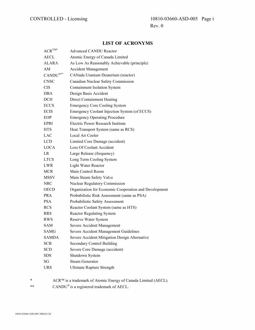
LIST OF ACRONYMS ACRTM* Advanced CANDU Reactor AECL Atomic Energy of Canada Limited ALARA As Low As Reasonably Achievable (principle) AM Accident Management CANDU** CANada Uranium Deuterium (reactor) CNSC Canadian Nuclear Safety Commission CIS Containment Isolation System DBA Design Basis Accident DCH Direct Containment Heating ECCS Emergency Core Cooling System ECIS Emergency Coolant Injection System (of ECCS) EOP Emergency Operating Procedure EPRI Electric Power Research Institute HTS Heat Transport System (same as RCS) LAC Local Air Cooler LCD Limited Core Damage (accident) LOCA Loss Of Coolant Accident LR Large Release (frequency) LTCS Long Term Cooling System LWR Light Water Reactor MCR Main Control Room MSSV Main Steam Safety Valve NRC Nuclear Regulatory Commission OECD Organization for Economic Cooperation and Development PRA Probabilistic Risk Assessment (same as PSA) PSA Probabilistic Safety Assessment RCS Reactor Coolant System (same as HTS) RRS Reactor Regulating System RWS Reserve Water System SAM Severe Accident Management SAMG Severe Accident Management Guidelines SAMDA Severe Accident Mitigation Design Alternative SCB Secondary Control Building SCD Severe Core Damage (accident) SDS Shutdown System SG Steam Generator URS Ultimate Rupture Strength
* ACR� is a trademark of Atomic Energy of Canada Limited (AECL). ** CANDU is a registered trademark of AECL.

CONTROLLED - Licensing 10810-03660-ASD-005 Page ii Rev. 0
TABLE OF CONTENTS
SECTION PAGE
10810-03660-ASD-005 2004/01/28
1. INTRODUCTION................................................................................................1-1
2. SEVERE ACCIDENTS .......................................................................................2-1
3. DESIGN PROVISIONS TO PREVENT CORE DAMAGE ...............................3-1
3.1 SAM Boundary Conditions..................................................................................3-2 3.2 Design Provisions for SAM .................................................................................3-2
4. DESIGN PROVISIONS TO RETAIN CORE WITHIN VESSELS ...................4-1
4.1 Retention in Fuel Channels ..................................................................................4-2 4.1.1 SAM Boundary Conditions............................................................................4-3 4.1.2 Design Provisions for SAM ...........................................................................4-4 4.2 Retention in Calandria Vessel ..............................................................................4-9 4.2.1 SAM Boundary Conditions..........................................................................4-12 4.2.2 Design Provisions for SAM .........................................................................4-13 4.3 Retention in Shield Tank....................................................................................4-14 4.3.1 SAM Boundary Conditions..........................................................................4-15 4.3.2 Design Provisions for SAM .........................................................................4-15
5. DESIGN PROVISIONS TO TERMINATE PROGRESS OF CORE DAMAGE ............................................................................................................5-1
5.1 Termination in Fuel Channels ..............................................................................5-1 5.1.1 SAM Boundary Conditions............................................................................5-2 5.1.2 Design Provisions for SAM ...........................................................................5-2 5.2 Termination in Calandria Vessel..........................................................................5-5 5.2.1 SAM Boundary Conditions............................................................................5-5 5.2.2 Design Provisions for SAM ...........................................................................5-5 5.3 Termination in Shield Tank..................................................................................5-6 5.3.1 SAM Boundary Conditions............................................................................5-6 5.3.2 Design Provisions for SAM ...........................................................................5-7 5.4 Termination in Reactor Vault (Containment) ......................................................5-7 5.4.1 SAM Boundary Conditions............................................................................5-7 5.4.2 Design Provisions for SAM ...........................................................................5-8 5.5 Termination in Calandria Vault (Containment) ...................................................5-8 5.5.1 SAM Boundary Conditions............................................................................5-9 5.5.2 Design Provisions for SAM ...........................................................................5-9
6. DESIGN PROVISIONS TO MAINTAIN CONTAINMENT INTEGRITY ......6-1
6.1 Containment Pressurization..................................................................................6-3 6.1.1 SAM Boundary Conditions............................................................................6-3 6.1.2 Design Provisions for SAM ...........................................................................6-4

CONTROLLED - Licensing 10810-03660-ASD-005 Page iii Rev. 0
TABLE OF CONTENTS
SECTION PAGE
10810-03660-ASD-005 2004/01/28
6.2 Hydrogen Control.................................................................................................6-5 6.2.1 SAM Boundary Conditions............................................................................6-7 6.2.2 Design Provisions for SAM ...........................................................................6-7 6.3 Corium-Concrete Interactions ............................................................................6-10
7. DESIGN PROVISIONS TO MINIMIZE OFF-SITE RELEASES .....................7-1
7.1 SAM Boundary Conditions..................................................................................7-2 7.2 Design Provisions for SAM .................................................................................7-2
8. CLOSING REMARKS ........................................................................................8-1
9. REFERENCES.....................................................................................................9-1
FIGURES
Figure 3-1 Actions to Prevent Fuel and Pressure Tube Deformations ..................................3-2
Figure 4-1 ACR Process Vessels ...........................................................................................4-1 Figure 4-2 Fuel Channel Deformations (conceptual) ............................................................4-2
Figure 4-3 Main Moderator System Flow Diagram ..............................................................4-6
Figure 4-4 Moderator Cover Gas System ..............................................................................4-7
Figure 4-5 Emergency Coolant Injection System..................................................................4-8
Figure 4-6 Reserve Water System Flow Diagram .................................................................4-8
Figure 4-7 Calandria and Shield Tank Assembly ..................................................................4-9
Figure 4-8 Calandria Conditions upon Core Collapse (conceptual) ....................................4-10
Figure 4-9 Boundary of Calandria Vessel during Core Disassembly (conceptual).............4-10
Figure 4-10 Calandria Conditions after Debris Compaction (conceptual) ............................4-11
Figure 4-11 Shield Tank Conditions upon Calandria Failure (conceptual) ...........................4-14
Figure 4-12 Shield Tank Location in Reactor Vault..............................................................4-16
Figure 5-1 Flow Diagram of Long Term Cooling System.....................................................5-4
Figure 5-2 Shield Tank Conditions prior to Internal Flooding (conceptual) .........................5-6
Figure 5-3 Calandria Vault Conditions upon Calandria Vessel Failure (conceptual) ...........5-9
Figure 6-1 Active Containment Mixing.................................................................................6-9
Figure 6-2 Passive Containment Mixing (conceptual) ..........................................................6-9

CONTROLLED - Licensing 10810-03660-ASD-005 Page iv Rev. 0
TABLE OF CONTENTS
SECTION PAGE
10810-03660-ASD-005 2004/01/28
CANDIDATES FOR COST/RISK BENEFIT REVIEW
SAMDA Candidate 1 Emergency Cross-Connections of Safety Grade Systems .................3-4
SAMDA Candidate 2 Calandria Head Tank – Compensation for Liquid Expulsion............4-4
SAMDA Candidate 3 RWS Valves – Emergency Connection to Alternate Power Supply.................................................................................................4-6
SAMDA Candidate 4 LTCS – Emergency Connections to Alternate Services ....................5-3
SAMDA Candidate 5 RWS – Emergency Connection for Water Recirculation...................5-4
SAMDA Candidate 6 Reactor Vault - Floor Contour ...........................................................5-8
SAMDA Candidate 7 LACs – Emergency Connections to Alternates Services ...................6-5
SAMDA Candidate 8 Containment Sprays ...........................................................................6-5
SAMDA Candidate 9 Passive Suppression of Steaming from Process Vessels....................6-5
SAMDA Candidate 10 Hydrogen Control...............................................................................6-8 SAMDA Candidate 11 Off-Site Release Control – Containment Venting..............................7-2

CONTROLLED - Licensing 10810-03660-ASD-005 Page 1-1 Rev. 0
10810-03660-ASD-005 2004/01/28
1. INTRODUCTION
Historically, the effort by the Canadian nuclear industry was aimed at the prevention of severe accidents by developing robust reactor designs and ensuring a high reliability of vital reactor systems. Severe core damage (SCD) accidents were considered of sufficiently low probability that no regulatory requirements were warranted. Limited core damage (LCD) accidents are traditionally considered in the CANDU reactor design. (SCD and LCD accident categories are briefly outlined in Section 2). The Canadian Nuclear Safety Commission (CNSC) is currently developing regulatory guidelines for advanced reactors, which extend to SCD accidents. For new reactor designs, the US Nuclear Regulatory Commission (NRC) requires, among other things, the evaluation of design alternatives to reduce the radiological risk from a severe accident by preventing substantial core damage (i.e., preventing a severe accident) or by limiting releases from the plant in the event that substantial core damage occurs (i.e., mitigating the impacts of a severe accident), References [1] and [2]. The purpose of such evaluation is to establish whether there are any cost-effective severe accident mitigation design alternatives (SAMDAs) that should be added to the facility. The SAMDAs will be assessed for the Advanced CANDU Reactor (ACR) to confirm that its design provisions for severe accident management (SAM) are effective and efficient. Such exercise is useful for reactor design optimization and is one of the requirements for international licensing of the reactor. Relevant reactor design features are those provided to facilitate the SAM. The senior group of experts on SAM assembled by the Organization for Economic Cooperation and Development (OECD) defines the SAM as follows (Reference [3]): Severe accident management consists of those actions that are taken by the plant staff during the course of an accident to prevent core damage, terminate progress of core damage and retain the core within the vessel, maintain containment integrity, and minimize off-site releases. Severe Accident Management also involves pre-planning and preparatory measures for SAM guidance and procedures, equipment modifications to facilitate procedure implementation, and severe accident training. This definition includes the concept that there is some overlap between what is referred to as Accident Management and Severe Accident Management. There are variations of the SAM definition (e.g., Reference [4]), but the substance is the same in all definitions. This report uses the OECD definition to organize the SAM topics. For each topic highlighted by bold type in the above citation, SAM-related design features of the ACR are systematically reviewed (Sections 3 through 7). The review compiles background information, broadly identifies SAM boundary conditions, examines the ACR design features (as described in References [5] and [6]) in the context of pertinent boundary conditions and identifies the candidates for a SAMDA assessment (flagged as ‘SAMDA Candidate’). It should be noted that the SAMDA candidates are not recommendations for design modification or implementation. They are simply SAM-related design topics for which a documented, risk-informed assessment will be needed to explain the defence in depth provided by the ACR design. As noted above, such assessment is one of the international licensing requirements.

CONTROLLED - Licensing 10810-03660-ASD-005 Page 1-2 Rev. 0
10810-03660-ASD-005 2004/01/28
The systematic review of SAM-related features initializes the SAMDA assessment process. The full assessment also requires quantitative information on the cost of a SAMDA and its effect on the radiological risk (provided by Level 2 probabilistic safety assessment (PSA)1). The latter two elements are not yet available.
1 The US terminology for PSA is Probabilistic Risk Assessment (PRA).

CONTROLLED - Licensing 10810-03660-ASD-005 Page 2-1 Rev. 0
10810-03660-ASD-005 2004/01/28
2. SEVERE ACCIDENTS
In CANDU reactors, a core damage results from LCD accidents and SCD accidents, which are defined in Reference [7] and explained in Reference [8]. Both these accident categories are severe accidents according to the definition in Reference [9]. Reference [3] provides a brief overview of CANDU severe accident progression as follows: (In severe accidents), “the fuel elements are predicted to gradually slump down on the horizontal pressure tubes, which will in turn balloon or sag into contact with their concentric calandria tubes. If the surrounding calandria water (moderator) is present, the fuel cooling should be restored. If, however, calandria water is not available or is subsequently lost, the fuel channels eventually lose their mechanical strength and slump down onto the bottom of the calandria vessel. It is estimated that this process would take five to six hours, affording time and opportunity for intervention. In most Canadian CANDU reactors, the calandria vessel is surrounded by a water filled biological shield tank. If shield tank water inventory can be maintained, it is expected that the entire mass of core material will likely be retained in the calandria. If the shield tank water inventory cannot be maintained, the core material will eventually (estimated 1 day) penetrate the calandria vessel and sometime after that (approximately 50 hours) the shield tank, eventually ending up on the containment floor, which is expected to be flooded with RCS, moderator and shield cooling system water.” The LCD accidents pertain to the first phase in the above citation, which ends with a rejection of core heat into the alternate moderator heat sink. These accidents involve widespread fuel failures and fuel/pressure tube deformations. However, in all LCD accidents, the fuel materials remain within the heat transport system (HTS)2 boundaries and the reactor core maintains a distorted but coolable geometry that is approximately constant after the initial transient3. The SCD accidents pertain to the subsequent phases in the above citation. These accidents involve significant amounts of fuel debris outside of the HTS boundaries. The debris (also commonly called ‘the corium’) does not have readily definable characteristic (i.e., it can change its geometry and properties according to prevailing boundary conditions). The corium could be located in externally cooled, metal process vessels (e.g., the calandria vessel or the shield tank), or in plant volumes that cannot be externally cooled (e.g., in a concrete calandria vault, which is an alternative to the metal shield tank, or on the containment floor). The ACR provides active as well as passive heat sinks for all water volumes surrounding the reactor core (discussed in the following sections). Although the above-cited severe accident progression applies generically, there are numerous possibilities for SAM interventions such that breaches in multiple debris-retention boundaries will be of an extremely low probability in the ACR.
2 The US terminology for HTS is reactor coolant system (RCS). 3 LCD accidents also include the so called single channel events that displace a small amount of fuel (up to
12 short fuel bundles) outside of the RCS boundaries as part of the initiating event (Reference [8]). For the single channel events, this statement applies to the fuel that was not ejected by the initiating event.

CONTROLLED - Licensing 10810-03660-ASD-005 Page 3-1 Rev. 0
10810-03660-ASD-005 2004/01/28
3. DESIGN PROVISIONS TO PREVENT CORE DAMAGE
For accidents at decay power, a LCD accident invariably precedes a SCD accident (Section 2). Hence, the “prevention of core damage” in the OECD definition could mean a prevention of LCD accident if core damage is taken to mean appreciable deformations of core components. Alternatively, it could mean a mitigation of LCD accident if core damage is taken to mean a loss of reactor core structural integrity. In this section, the first of these two interpretations is adopted. Thus, the prevention of core damage is the prevention of significant deformations of fuel bundles and pressure tubes (i.e., the prevention of LCD accident). The second possible interpretation is actually a “retention of core within vessels”, where ‘vessels’ are the fuel channels (i.e., a composite of pressure and calandria tubes, where either of the tubes could be the retaining boundary). The retention is discussed in Section 4. The prevention of fuel and pressure tube deformations is normally accomplished by the conventional accident management (AM) rather than by the severe accident management. The accident management is executed by operators in the control room right from the start of the accident. It employs engineered safety systems and their support systems according to rehearsed emergency operating procedures (EOPs). The equipment used for conventional accident management typically operates within its design envelope. Severe accident management might be used to prevent deformations if an accident is progressing slowly such that time is available to transfer from AM to SAM before the fuel and pressure tubes have deformed. During SAM, the plant technical management takes on a primary decision-making role in advising the control room operators and deploying in-plant and onsite staff in implementing severe accident management guidelines (SAMGs). The SAM can only commence after the management team has assembled (i.e., which takes some time relative to the start of the accident). SAMGs outline strategies and uses of alternative systems in ways that were not envisioned (or evaluated) in the licensing basis of the plant. Such strategies would be employed only if the EOPs were ineffective (e.g., due to additional failures of systems used by the EOPs). Otherwise, the plant technical management would follow the EOPs. The preceding discussion illustrates the overlap between accident management and severe accident management, which is recognized by the OECD definition of SAM cited in Section 1. This overlap is most pronounced for the topic of core damage prevention. This section does not concern itself with the systems used for normal accident management. These systems are identified in Figure 3-1 (Section 3.2) and they are well described elsewhere (e.g., Reference [6]). Stringent reliability requirements are set by the CNSC for all safety systems (i.e., unavailability ≤ 10-3 years/year for each of the two shutdown systems (SDS), the emergency core cooling system (ECCS) and the containment system, Reference [7]). A design target has been defined for the summed SCD accident frequency for all internal and external initiators (i.e., < 10-5 per year4, Reference [7]). This latter frequency impacts on the reliability requirements for the remaining plant systems. All systems used for normal accident management are closely scrutinized by the deterministic analyses as well as by the PSA. The focus of this section is on other design features that could be used to prevent fuel and channel deformations during SAM. 4 This total frequency includes external events, except seismic (a seismic margin assessment will be
performed for earthquakes).

CONTROLLED - Licensing 10810-03660-ASD-005 Page 3-2 Rev. 0
10810-03660-ASD-005 2004/01/28
3.1 SAM Boundary Conditions
By the time the SAM commences, the reactor has been shut down for a period of time5. The core damage is prevented when the coolant in the HTS removes the fuel heat (Reference [9]). At decay power levels, a sufficient condition to prevent the fuel and pressure tube deformations is keeping the inside of the pressure tubes flooded with liquid water (Reference [8]).
3.2 Design Provisions for SAM
Figure 3-1 outlines the ACR options for keeping the fuel covered by water. All these options can be accomplished by the conventional accident management provisions.
SAM starts
HTSintact
?
Headersvoided?
Maintain orestablish SG
heat sink
Maintain orestablish LTCS
heat sink
Provide steamrelief from SG
Provide watermakeup to SG
Circulate coolantthrough HX
Provide servicewater to HX
Reduce HTSpressure using SG
Refill aboveheaders
using ECIS
Successful ?
HTSpressurized
?
Very small break
Establish &maintain HTS
makeup
Establish &maintain HTS
makeup
Refill aboveheaders
using ECCS
Refill aboveheaders
using RWS
Larger break
AND
OR
AND AND
OR
N
Y
Con
sequ
entia
l cha
nnel
failu
re
ORRefill above
headers usingHTS feed
N
Y
Y
N OR Steaming intocontainment
SG cool-downsuccessful
SG cool-downunsuccessful
AND ANDOR
Y N
Figure 3-1 Actions to Prevent Fuel and Pressure Tube Deformations
5 The ACR has multiple, diverse means of quickly shutting down the reactor (Sections 6.2, 6.3 and 7.5.1 in
Reference [6]). Ensuring that the reactor is the shut down is the first step of any EOP.

CONTROLLED - Licensing 10810-03660-ASD-005 Page 3-3 Rev. 0
10810-03660-ASD-005 2004/01/28
Reference [10] (Item I) identifies the provision of reliable HTS depressurization as one of the requirements for preventing and mitigating severe core damage. In pressure vessel reactors, the fuel at decay power could melt before a voided (or partially voided) vessel fails. A molten material could then be ejected as a high-velocity jet into the containment6, causing a major challenge to the containment integrity at the same time when there is a major radioactivity release into the containment. Depressurizing the vessel prevents this high-velocity melt ejection by permitting the fuel to be flooded before it melts using water sources at modest injection pressure. It should be noted that a pressurized melt ejection is not relevant to CANDU reactors. Should the HTS become voided at high pressures, a fuel channel failure is unavoidable at modest fuel temperatures7 (Reference [8]). This channel failure depressurizes the HTS well before the fuel could be liquefied within any of the channels. Hence, the ACR has two means of HTS depressurization to prevent fuel melting within the HTS boundaries:
• It has two independent, highly reliable, engineered systems to depressurize the HTS to below the injection pressure of the emergency coolant injection system (ECIS) using the main steam safety valves (MSSVs), which are the conventional accident management provisions (Section 6.1.2.2 in Reference [6]); and
• It has an inherent (non-engineered) “thermal fuse” (in the form of channel failure(s)) which comes into play in severe accidents if the engineered depressurization is unavailable or ineffective. The inherent channel failure accommodates timely flooding of the fuel by passive water supplies from the ECIS or the reserve water system (RWS) before any fuel could liquefy8.
Past analyses of light water reactors (LWRs) have identified the so-called containment bypass (e.g., an interfacing system LOCA) as a significant contributor to large off site releases. The US NRC has set the following requirements related to preventing the interfacing system LOCA (Reference [10]): • All systems and subsystems connected to the RCS, which extended outside the primary
containment boundary, must be designed to the extent practicable to ultimate rupture strength (URS) of at least equal to full RCS pressure.
• The designer must determine by evaluation that, for interfacing systems or subsystems which do not meet the full RCS URS requirement, the degree and quality of isolation or reduced severity of the potential pressure challenges are sufficient to preclude an intersystem LOCA.
• Additional testing and control room alarm capabilities must be implemented to help reduce the probability of an intersystem LOCA.
These are “generic” accident prevention principles, which have long been recognized in CANDU reactor designs. The ACR will demonstrate the compliance with these principles.
6 A high-velocity jet of the molten corium could be finely fragmented, causing the so-called Direct
Containment Heating (DCH). 7 Fuel temperatures are well below Zr melting point. 8 This ‘non-engineered’ HTS pressure relief involves some limited core damage, but prevents fuel melting.
It could involve a rupture of single channel (likely) or few channels (less likely) as described in Reference [8].

CONTROLLED - Licensing 10810-03660-ASD-005 Page 3-4 Rev. 0
10810-03660-ASD-005 2004/01/28
So far, only the features for conventional accident prevention and inherent features have been discussed. What are the SAMDAs relevant to the topic of this section (i.e., the prevention of LCD accidents by manual interventions in the long term when normal accident management is ineffective)? Design options to be considered for SAM are outlined below as SAMDA Candidate 1.
SAMDA Candidate 1 Emergency Cross-Connections of Safety Grade Systems
The emergency cross-connections outlined below would not be permanent links, but engineered provisions for “jumpers” that could be installed during a progression of severe accident. • Emergency cross-connections of non-safety grade water systems to safety grade injection
systems. In the context of Figure 3-1, these could be provisions to connect an external (portable) water supply to the service side of long term cooling system (LTCS) heat exchangers, the secondary side of steam generators, etc.
• Emergency cross-connections of non-safety grade power supplies to safety grade power supplies. These could be provisions to connect a portable power supply to LTC pumps, motorized valves, etc.
• Emergency cross-connections of non-safety grade gas supplies to safety grade gas supplies. This could be a provision to connect bottled gas supply to pneumatic valves.
It should be noted that any cross-connection between safety and non-safety grade systems must be treated with extreme caution. Stringent separation requirements are in place for all safety grade systems to enhance protection against common cause events (Section 2.1.3 in Reference [6]).
Analyses of PSA results (which are a part of the PSA process) identify which post-accident cross-connections would be beneficial (in terms of avoiding fuel and pressure tube deformations) and feasible (it terms of having enough time available to implement them9). A focused search of ACR layouts can then be performed for possible (SAM-related) ‘jumpers’. This search makes sense only in a well advanced stage of the design process, when the layouts are close to being final. This is why the emergency cross-connections are treated only as high-level topics in this report (i.e., the PSA results are not yet available and many layout details have not yet been finalized).
9 Systems can be connected via jumpers only if the accident progresses slowly enough that field actions are
possible.
CONTROLLED - Licensing 10810-03660-ASD-005 Page 4-1 Rev. 0
10810-03660-ASD-005 2004/01/28
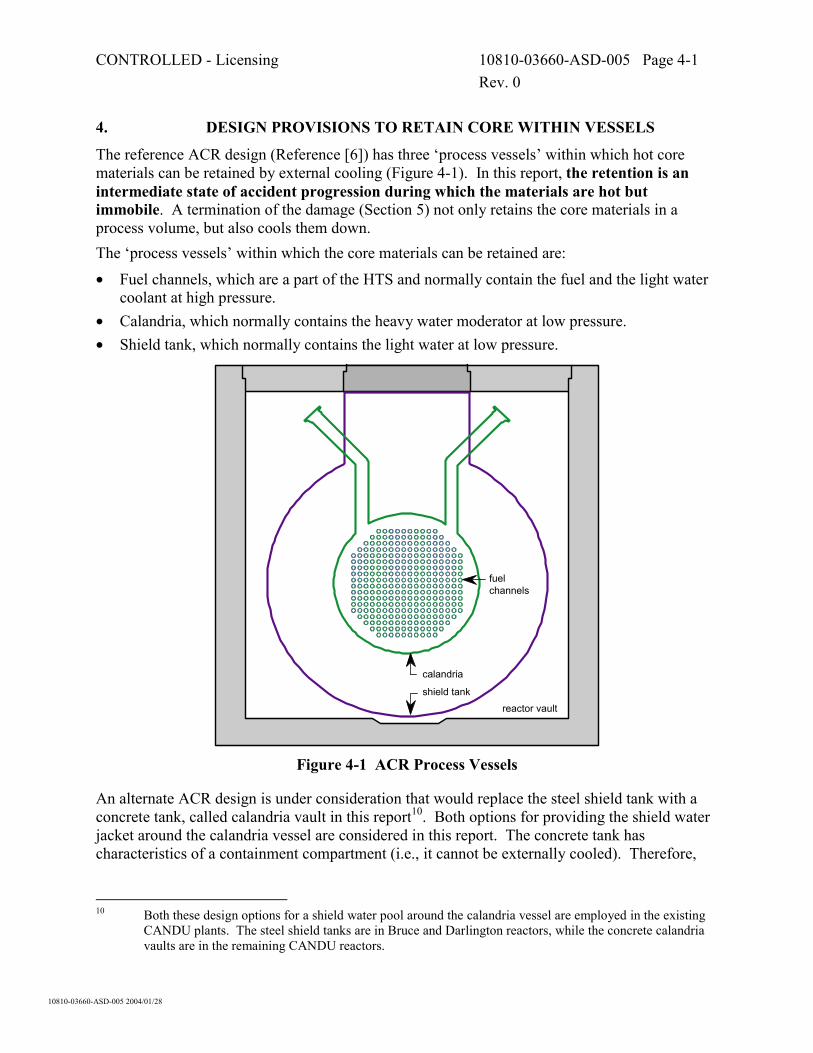
4. DESIGN PROVISIONS TO RETAIN CORE WITHIN VESSELS
The reference ACR design (Reference [6]) has three ‘process vessels’ within which hot core materials can be retained by external cooling (Figure 4-1). In this report, the retention is an intermediate state of accident progression during which the materials are hot but immobile. A termination of the damage (Section 5) not only retains the core materials in a process volume, but also cools them down. The ‘process vessels’ within which the core materials can be retained are:
• Fuel channels, which are a part of the HTS and normally contain the fuel and the light water coolant at high pressure.
• Calandria, which normally contains the heavy water moderator at low pressure. • Shield tank, which normally contains the light water at low pressure.
fuelchannels
shield tank
calandria
reactor vault
Figure 4-1 ACR Process Vessels
An alternate ACR design is under consideration that would replace the steel shield tank with a concrete tank, called calandria vault in this report10. Both options for providing the shield water jacket around the calandria vessel are considered in this report. The concrete tank has characteristics of a containment compartment (i.e., it cannot be externally cooled). Therefore,
10 Both these design options for a shield water pool around the calandria vessel are employed in the existing
CANDU plants. The steel shield tanks are in Bruce and Darlington reactors, while the concrete calandria vaults are in the remaining CANDU reactors.

CONTROLLED - Licensing 10810-03660-ASD-005 Page 4-2 Rev. 0
10810-03660-ASD-005 2004/01/28
the alternate ACR design has two ‘process vessels’ for the retention of hot core materials by external cooling.
4.1 Retention in Fuel Channels
The fuel channels are invariably depressurized by the time the fuel heats up to highly elevated temperatures11. Heat rejection paths to the water volume in the calandria are established by fuel and pressure tube deformations while the fuel is solid (Figure 4-2) 12. Under these conditions, the only prerequisite for retaining the hot, solid fuel debris within the fuel channels is to maintain all the channels submerged in liquid water on the outside (Reference [8]).
NOMINAL
SAGGED with SLUMPED FUEL BALLOONED with SLUMPED FUEL
calandria tube
pressure tube
fuel element
annuls gap
approximately to scale
H2O coolant
D2O moderator
SAGGED with DEFORMED FUEL BALLOONED with DEFORMED FUEL
Figure 4-2 Fuel Channel Deformations (conceptual)
11 The HTS is either depressurized by the initiating event and subsequent automatic and/or manual system
actions, or the inherent “thermal fuse” (in the form of consequential channel failure(s)) has come into play, which is described in Reference [8].
12 Terms ‘sagged’, ‘ballooned’ and ‘slumped’ geometries are commonly used to label the conditions shown in Figure 4-2. Note that the schematic illustration does not apply uniformly in the axial direction (i.e., along the length of the channel). Spacers between pressure and calandria tubes cause local separations between the two tubes, with attendant axial conduction of heat to surfaces in contact.

CONTROLLED - Licensing 10810-03660-ASD-005 Page 4-3 Rev. 0
10810-03660-ASD-005 2004/01/28
4.1.1 SAM Boundary Conditions
Boundary conditions to retain deformed fuel and pressure tubes within calandria tubes are: a) A fast water make-up is desirable to compensate for any liquid expulsion from the calandria
such that the top-most row of fuel channels always remains below the water level13. AND
b) An active heat sink is needed for the calandria water volume in order to avoid boiling14. This heat sink is provided when: 1) A forced circulation (pumped flow) is available to move water from the calandria through
the heat exchanger. AND
2) A service water flow is available on the secondary (service) side of the heat exchanger. OR
c) A passive heat sink (provided by steaming and liquid make up) is needed. Such heat sink is provided when: 1) A steam relief path is available from the calandria vessel.
AND 2) A water makeup path is available to the calandria vessel with sufficient capacity to
compensate for steaming. The limiting accident for make-up capacity is an in-core break with a total loss of ECC. The calandria fluid is at saturation temperature and reduced level after the HTS blowdown. Heat load to calandria commences at ~ 30 minutes (15 minutes for blowdown and 15 minutes for fuel heat up). Decay power at this time is ~ 2 % of full power (i.e., ~ 40 MW). This means a make up of ~ 18 L s-1. Out of core breaks will take a long time for the moderator to reach saturation temperature. Hence, a lower make-up capacity would be needed for breaks other than in-core breaks. AND
3) A liquid level measurement in the calandria is available for the operator to monitor that the water level is above the highest channel elevation and below the overflow elevation15. AND
4) Means are available to monitor the status of the water source. AND
5) Means are available to remotely control the supply of water into the calandria.
13 The liquid water is expelled when the moderator is at (or close to) the saturation temperature and the
rupture disk opens. A sudden pressure change causes a swell due to steam bubbles. The swollen two-phase fluid is relived instead of only steam. This results in a significantly reduced water level within the calandria at the end of the transient if no external liquid is added during the transient.
14 When there is no boiling, the calandria water level does not change. 15 The overflow is an indication that the supply can be adjusted/modulated in order to conserve the reserve
water inventory.

CONTROLLED - Licensing 10810-03660-ASD-005 Page 4-4 Rev. 0
10810-03660-ASD-005 2004/01/28
4.1.2 Design Provisions for SAM
Both ACR design alternatives can facilitate the above SAM conditions as explained below. a) To compensate for a liquid expulsion through the relief ducts, the following design features
are provided16: 1) The operator manually activates the RWS supply to the calandria (and/or to HTS if the
calandria disks burst due to an in-core rupture) before any uncovered channels start breaking down17. AND/OR
2) The liquid inventory in the calandria head tank (Figure 4-3), which returns into the calandria vessel soon after the calandria transient, is sufficient to keep the top-most channel row submerged in liquid (see SAMDA Candidate 2).
SAMDA Candidate 2 Calandria Head Tank – Compensation for Liquid Expulsion
The tank is to “accommodate D2O level changes in the calandria due to shrinkage and swell” (e.g., Section 5.3.1, Item f, Reference [6]). This is for normal operation. A SAM provision would accommodate a liquid expulsion following a moderator relief via the rupture disks such that all fuel channels remain submerged in liquid after the relief is completed. This is simply an issue of how much water remains in ACR calandria vessel after the initial transient and how much water can be ‘passively’ returned from the head tank. Ideally, the sum would provide enough water to keep the top-most row of channels submerged in any accident. This would, in turn, guarantee ample time for the manual water make-up from the RWS. Ongoing analyses may well show that all channels remain submerged, thereby removing this topic from the list of SAMDA candidates.
b) Main moderator system (Figure 4-3) has ample heat removal capacity when available. The
normal heat load (~ 80 MW, Table 13.2-1 of Reference [6]) is much higher than the largest post-accident heat load (~ 40 MW, Item C.2 in Section 4.1.1). A single pump and a single heat exchanger are adequate. Two pumps are provided, supplied with Class III power (Section 5.3.2, Reference [6]). However, these pumps would not operate with a reduced water level in the calandria vessel (the pump suction line is at high elevation in order to avoid moderator draining in case of a break in the suction line). Two heat exchangers are available, provided with service water supply on Class III power. These exchangers would not be effective in the absence of forced flow.
c) The passive heat sink is provided as follows:
16 The ECC systems are not available for the moderator to act as the heat sink. 17 Based on analyses of existing CANDU reactors, adequate time (more than 15 minutes) is available for this
operator action. This will be confirmed by ACR-specific analyses.

CONTROLLED - Licensing 10810-03660-ASD-005 Page 4-5 Rev. 0
10810-03660-ASD-005 2004/01/28
1) Two steam relief paths are provided: One path is through two bleed valves of the cover gas system (Figure 4-4), which ultimately vent steam into containment18. The other path is through four rupture disks on the calandria vessel, which vent steam directly into the containment19.
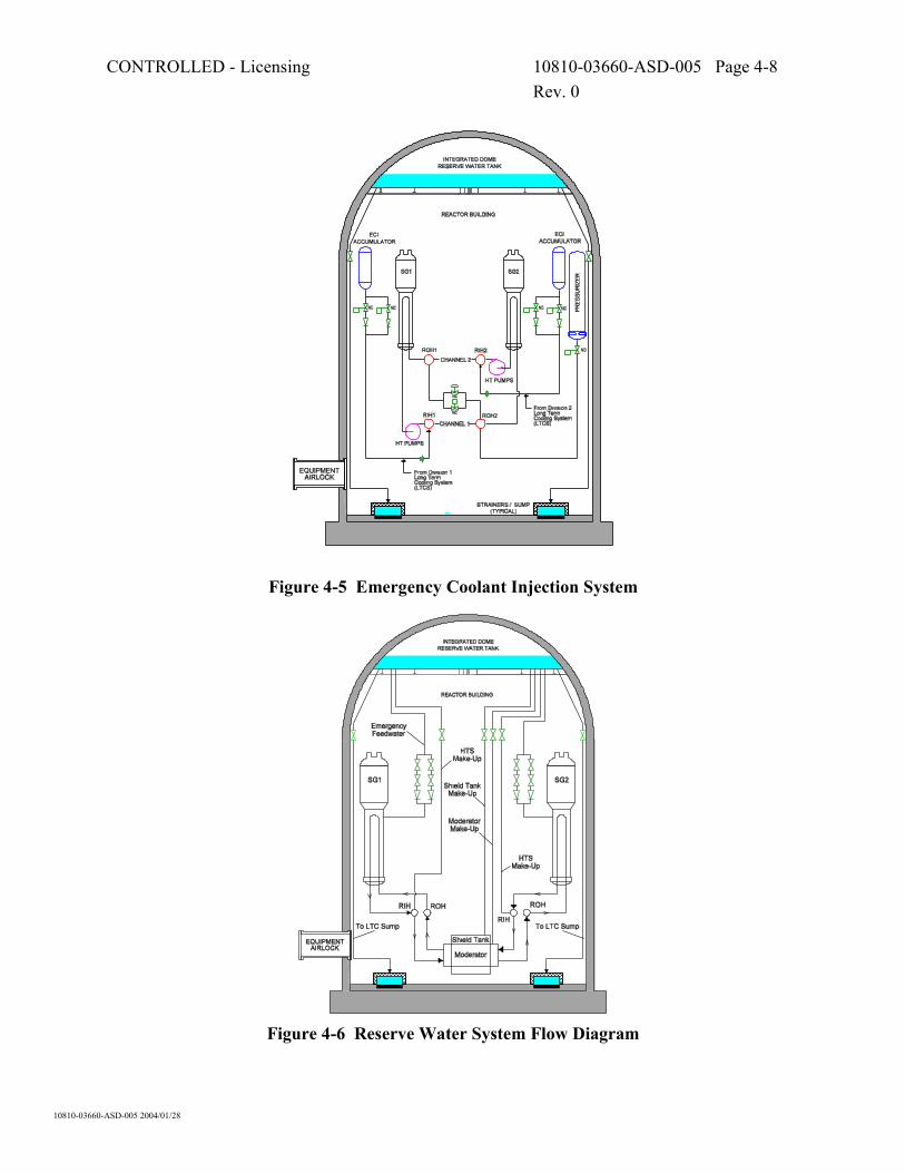
2) Water make up (by gravity) from the reserve water tank of RWS (Figure 4-6) has sufficient flow capacity to compensate for steaming at relevant decay power levels (i.e., the capacity is well in excess of 18 kg/s by about an order of magnitude).
3) Liquid level is measured in the calandria head tank (Figure 4-3) as follows: Three narrow range transmitters measure level from the top of the head tank to the centreline of the top row of channels. The instruments are not exposed to harsh environment20 and are highly reliable. A single wide-range transmitter (to measure the full range of calandria levels) is also provided, but this measurement is not essential for SAM21. High and low levels are announced (Section 5.3.3.3, Reference [6]) in the main control room as well as in the secondary control building. The level signals are also used for the automatic trip22 logic (Table 7.2.1-1 and Table 7.2.2-1, Reference [6]).
4) Instrumentation is provided to measure pressure23, temperature and level in the reserve water tank of RWS and the flow from the RWS to its customers (Section 9.2.7.3, Reference [6])24.
5) Means to control the make up flow under SAM conditions are provided: i) Status indications and remote controls are provided for all motorized valves in the
RWS (Section 9.2.7.3, Reference [6]). ii) The motorized valves are powered by the uninterruptible Class II supply (see
SAMDA Candidate 3).
18 This relief path is relevant to accidents with all fuel channels intact. 19 This path will invariably open following an in-core rupture. 20 This will be confirmed by assessment of operability under severe accident conditions. 21 The operator needs to know when to add emergency water (i.e., level dropping to the top-most channel
rows) and when to stop adding water (i.e., level rising to overflow elevation). 22 The Canadian terms ‘trip’ is equivalent to US term ‘scram’. 23 The pressure in the RWS is the same as that in the containment (not counting the static head, which is
known from level measurement). This pressure measurement might simply be the containment pressure measurement.
24 The RWS instrumentation is not yet finalized. This instrumentation can be located within the reserve water pool such that it is protected from a harsh environment that is likely to exist during SAM. The important parameters to measure are the reserve water level and the flow from the tank. The level is the indicator of the water reserve status (i.e., how much water is left). The flow measurement is important to confirming that enough water is being supplied to the target process vessel. As explained in Section 5, a low water supply rate could actually be harmful under some accident circumstances (by facilitating exothermic chemical reactions of hot core materials with steam without stopping them). The flow adequacy can be deduced from water level measurements in process volumes containing the hot fuel, but a direct measurement is preferable under the stressful SAM conditions.

CONTROLLED - Licensing 10810-03660-ASD-005 Page 4-6 Rev. 0
10810-03660-ASD-005 2004/01/28
iii) The valves will be environmentally qualified for post-LOCA conditions (Section 9.1, Reference [6]) and assessed for their operability under severe accident conditions.
SAMDA Candidate 3 RWS Valves – Emergency Connection to Alternate Power Supply
Connections to facilitate alternate services are already identified generically as SAMDA Candidate 1. This is a subset of the generic item. The alternate power supply connection is particularly important for the RWS valves. The RWS is a key system for mitigating a prolonged loss of all electrical power. Class II power lasts only for a limited time under these circumstances (several hours). The probability of a sustained plant “blackout” must be minute, given that the ACR has four on-site diesel generators. A cost/risk benefit assessment would be useful, because a prolonged blackout is widely perceived to be a significant contributor to the radiological risk and this alternative would lessen the impact of the blackout.
HEAT EXCHANGER
TO RCWSYSTEM
FROM RCWSYSTEM
TO RCWSYSTEM
FROM RCWSYSTEM
HEAT EXCHANGER
FROM MOD COVER GAS SYSTEM
HEAD TANK
CALANDRIA
RUPTURE DISK
FROM/TO D2O SUPPLYSYSTEM
FROM MOD PURIFICATIONSYSTEM
FROM MOD LIQUIDPOISON SYSTEM
STRAINER (Commissioning Only)
PUMP PUMP
TO MOD COVER GAS SYSTEM
TO MOD PURIFICATIONSYSTEM
TO MOD LIQUID POISON SYSTEM TO MOD D2O COLLECTION SYSTEM
TO MOD SAMPLING SYSTEM
TO MOD D2O COLLECTION SYSTEM TO MOD D2O COLLECTION SYSTEM
FROM RESERVEWATER SYSTEM
STRAINER (Commissioning Only)
CalandriaBottom
FlushingValve
D2O Supply Valve
Figure 4-3 Main Moderator System Flow Diagram

CONTROLLED - Licensing 10810-03660-ASD-005 Page 4-7 Rev. 0
10810-03660-ASD-005 2004/01/28
Figure 4-4 Moderator Cover Gas System
CONTROLLED - Licensing 10810-03660-ASD-005 Page 4-8 Rev. 0
10810-03660-ASD-005 2004/01/28
Figure 4-5 Emergency Coolant Injection System
Figure 4-6 Reserve Water System Flow Diagram

CONTROLLED - Licensing 10810-03660-ASD-005 Page 4-9 Rev. 0
10810-03660-ASD-005 2004/01/28
4.2 Retention in Calandria Vessel
The calandria, the two end shields, and the shield tank (including its end walls and shield tank extension) constitute a multi-compartment structure (Figure 4-7). An alternate ACR design replaces the shield tank and its extension with a concrete, steel lined calandria vault. The calandria vessel (discussed below) is the same in either design.
Figure 4-7 Calandria and Shield Tank Assembly
The calandria vessel is a horizontal cylinder enclosed at each end by circular flat plates (calandria tubesheets). The calandria tubes pass horizontally through the calandria vessel and are rolled into the calandria side tubesheets at each end, thereby completing the calandria vessel boundary. The calandria vessel contains heavy water moderator. The end shields are welded on the horizontal faces of the calandria vessel and are integral parts of the calandria assembly. They are short cylindrical shells enclosed at each end by tubesheets, and spanned horizontally by lattice tubes. The end shields contain materials for biological shielding (carbon steel balls and demineralized light water). As explained in Reference [8], hot core materials relocate into the calandria vessel while it still contains a significant pool of water. Figure 4-8 illustrates the conditions in the calandria vessel following sudden debris relocation (a core collapse). The debris entering the water pool is largely solid, but there is a lot of it and the hot materials enter the residual water pool quite rapidly (on the timescale of minutes). This type of debris relocation cannot cause a steam

CONTROLLED - Licensing 10810-03660-ASD-005 Page 4-10 Rev. 0
10810-03660-ASD-005 2004/01/28
explosion. Nevertheless, it would cause a major steaming surge and the corresponding pressure excursion in the calandria vessel. Pressure and calandria tubes are broken during the core disassembly process. Following the core collapse, the calandria vessel boundary extends through the lattice tubes of the end shields to the end fitting bellows (Figure 4-9). Also, the calandria vessel internal volume becomes interconnected to the voided HTS via the feeder pipes. When the core collapses, debris weight and heat loads are predominantly applied to the calandria shell (Figure 4-8). The calandria tubesheets would come into contact with the corium only later, if the calandria vessel were allowed to dry out. The corium would eventually compact and partially liquefy in the dry calandria vessel, causing a direct contact of hot corium materials with the calandria tubesheets (Figure 4-10).
fragmentedchannelsegments
pulled offfuel channels
strongsteamsurges
solidifiedZircaloy
Figure 4-8 Calandria Conditions upon Core Collapse (conceptual)
Figure 4-9 Boundary of Calandria Vessel during Core Disassembly (conceptual)

CONTROLLED - Licensing 10810-03660-ASD-005 Page 4-11 Rev. 0
10810-03660-ASD-005 2004/01/28
to (1) heat exchangeror (2) containmentvia boil-off and make-up
radiation to surfaces
natural convectionof gases
conductionto end shieldsconduction�
& heat generationin solid corium
circulation& convectionin molten corium
fluid conditions inshield tank and end shields
corium properties& interactions
FP & H2release from corium
interactionwith containment
FP deposition& resuspension
Figure 4-10 Calandria Conditions after Debris Compaction (conceptual)
Broad requisites for retaining the hot core materials (i.e., corium) within the calandria vessel are: a) The internal pressure in the calandria vessel is kept sufficiently low such that the vessel
maintains definable boundaries following the reactor core disassembly25. AND
b) The walls of the calandria vessel remain sufficiently cool such the wall does not fail under the combined thermal and weight loads. This is satisfied when: 1) Outer surface of the wall is in contact with liquid water.
AND 2) Heat fluxes through the vessel wall are sufficiently low that a departure from nucleate
boiling is avoided on the outer wall surface. The low heat fluxes are inherent to the
25 Calandria vessel boundary failures would be tolerable provided such openings do not interconnect calandria
and shield tank volumes, or facilitate a spillage of liquefied corium from the calandria vessel. At issue is a gross failure of the calandria vessel, which could propagate into additional systems failures.

CONTROLLED - Licensing 10810-03660-ASD-005 Page 4-12 Rev. 0
10810-03660-ASD-005 2004/01/28
cylindrical calandria vessel geometry (Reference [8]) and, therefore, this requisite is automatically satisfied.
4.2.1 SAM Boundary Conditions
The following SAM boundary conditions satisfy the above requisites: a) The calandria overpressure protection provisions accommodate the steam surges due to the
reactor core collapse into the residual water pool present in the calandria vessel. AND
b) An active heat sink is available for shield water in the shield tank as well as in each of the two end shields. This heat sink is provided when: 1) Forced circulation (pump) is available to circulate the shield water through the three
volumes and the heat exchanger. AND
2) Service water flow is available through the heat exchanger. The sufficient active heat sink capacity removes the decay heat at the time when the calandria vessel dries out. Analyses for the ACR are not yet available. Analyses for the existing CANDU reactors (e.g., Reference [11]) indicate this debris dryout time will be > 10 hours. The corresponding decay heat is < 0.75 % of full power (< 15 MW). OR
c) A passive heat sink (provided by steaming and liquid make up) is available. This heat sink is provided when: 1) Steam relief paths are available from each of the three volumes surrounding the calandria
vessel26 which do not interfere with each other or with the liquid make up. AND
2) Water makeup paths into each of the three volumes are available with sufficient flow capacities to compensate for steaming. Most of the heat from the debris is transferred to the shield tank. The end shield load would be < 10 % of the total load27. The corresponding make up rates are < 7 L s-1 for the shield tank and < 0.5 L s-1 for each of the end shields. AND
3) Means are available for the operator to monitor that the water level in each of the three volumes is well above the corium elevation. AND
4) Means are available for the operator to monitor the status of makeup water source. AND
5) Means are available for the operator to remotely control the supply of water into each of the three volumes.
26 The shield tank and the two end shields become individual entities with different heat loads when forced
circulation is not available. 27 This is an engineering judgement based on geometry considerations.

CONTROLLED - Licensing 10810-03660-ASD-005 Page 4-13 Rev. 0
10810-03660-ASD-005 2004/01/28
4.2.2 Design Provisions for SAM
a) The calandria vessel is provided with large relief ducts and rupture disks, which are expected to maintain acceptable internal pressures within the calandria vessel during the core disassembly. The design intent is to ensure that the calandria integrity is maintained in SCD accidents. The worst challenge is a core collapse (schematically illustrated in Figure 4-8), which rapidly brings a large amount of hot, solid materials into contact with a residual water pool at the bottom of calandria vessel. Methodology is available to quantify the resulting steam surges (e.g., Reference [12]) and analyses are in progress to ascertain that the final design will meet this intent.
b) The shield cooling system can remove 2 x 7.2 MW (Table 13.2-1, Reference [6]). Decay heat load would be < 15 MW (see above). Both heat exchangers in service will be able to maintain shield water temperature close to the nominal operating conditions. A single heat exchanger and a single pump will be able to maintain sub-cooled water in the shield tank as well as the calandria end shields28. This system is not environmentally qualified for post-accident conditions, so it might not be available during a SCD accident. The environmental conditions are not particularly harsh while the system operates (i.e., the system still contains the sub-cooled water even in SCD accidents). Assessments of operation at elevated water temperatures (relevant to SCD accidents) will be performed to confirm the system operability.
c) The following provisions are made for the passive heat sink: 1) The steam relief from the shield cooling system is not particularly demanding while the
system operates in the passive heat sink mode (i.e., water boil-off and make-up). Bleed valves supplemented by rupture disks will undoubtedly have a sufficient steam relief capacity29.
2) The RWS can supply sufficient water make-up to the shield tank as well as to the calandria end shields (Figure 4-6)30,31.
3) The design basis (Reference [6], Section 7.4.5) requires that the system “will have sufficient displays, alarms, and controls to ensure that the shield tank and end shields have sufficient water inventory and are adequately cooled”. Provided this instrumentation is confirmed by assessment to withstand the SCD accident conditions (which are not particularly harsh, see above), this satisfies the SAM needs.
4) Instruments to monitor the status of makeup water source are provided (see Item 3.4 in Section 4.1.2 for additional information).
28 This will be confirmed by severe accident analyses, which are in progress. 29 Ongoing assessments are evaluating the relief requirements. A steady steaming in this mode of operation is
not limiting for steam relief. The relief must also accommodate steam surges associated with corium relocation into the shield tank discussed in Section 4.3.
30 The end shields are internally interconnected with the shield tank, so a single supply line is sufficient. 31 The limiting case for the end shield make-up is not the debris cooling, but a removal of heat losses from
pressure tubes (via the lattice tubes). These losses are normally 2.8 MW (Table 13.2.1 in Reference [6]) and could be slightly higher when the fuel debris is being retained in the fuel channels.

CONTROLLED - Licensing 10810-03660-ASD-005 Page 4-14 Rev. 0
10810-03660-ASD-005 2004/01/28
5) Electrically operated valves to remotely control the supply of water from the RWS into each of the three volumes of the shield cooling system are provided (see Item 3.5 in Section 4.1.2 for additional information).
4.3 Retention in Shield Tank
This topic is only relevant to the metal shield tank in the reference ACR design32. Figure 4-11 illustrates the conditions in the shield tank upon a calandria vessel failure. The corium enters the tank as slurry of molten and solid materials. The rate of corium relocation is unknown, but it is expected to be slow (Reference [8]). There is a potential for a steam explosion, although it is not inevitable that an explosion would occur. However, a strong steam surge will invariably occur due to corium quenching, the magnitude of which depends on how the corium fragments upon entering the residual water pool.
wall ablationby melt
melt-coolantinteractions
steam surgein both vessels
shield tank relief open
calandriarelief open
reactor vault is opento containment
Figure 4-11 Shield Tank Conditions upon Calandria Failure (conceptual)
Broad requisites for retaining the corium in the shield tank are the same as those for retaining the corium in the calandria vessel (Section 4.2): a) The internal pressure in the shield tank is kept sufficiently low such that the vessel maintains
definable boundaries following the reactor core disassembly33. AND
32 The calandria vault used in the alternate ACR design is not a ‘vessel’ but a ‘containment compartment’
which cannot be externally cooled. Therefore, the corium can only be retained in the calandria vault if the core damage is terminated in this vault (see Section 5.5).
33 Shield tank boundary failures would be tolerable provided such openings do not cause a spillage of liquefied corium into the containment.
CONTROLLED - Licensing 10810-03660-ASD-005 Page 4-15 Rev. 0
10810-03660-ASD-005 2004/01/28
b) The walls of the shield tank remain sufficiently cool such the wall does not fail under the combined thermal and weight loads. This is satisfied when the wall that is in contact with the corium is submerged in liquid water on the outside.
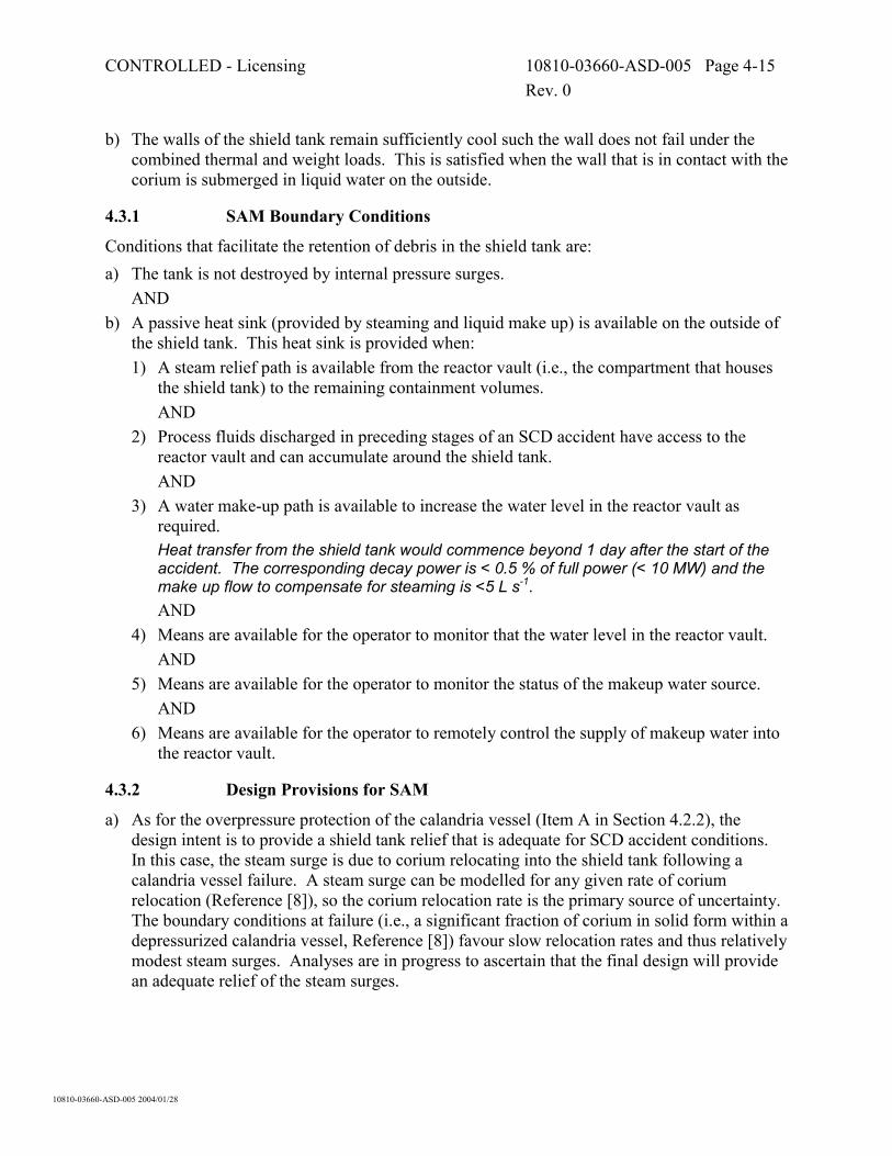
4.3.1 SAM Boundary Conditions
Conditions that facilitate the retention of debris in the shield tank are: a) The tank is not destroyed by internal pressure surges.
AND b) A passive heat sink (provided by steaming and liquid make up) is available on the outside of
the shield tank. This heat sink is provided when: 1) A steam relief path is available from the reactor vault (i.e., the compartment that houses
the shield tank) to the remaining containment volumes. AND
2) Process fluids discharged in preceding stages of an SCD accident have access to the reactor vault and can accumulate around the shield tank. AND
3) A water make-up path is available to increase the water level in the reactor vault as required. Heat transfer from the shield tank would commence beyond 1 day after the start of the accident. The corresponding decay power is < 0.5 % of full power (< 10 MW) and the make up flow to compensate for steaming is <5 L s-1. AND
4) Means are available for the operator to monitor that the water level in the reactor vault. AND
5) Means are available for the operator to monitor the status of the makeup water source. AND
6) Means are available for the operator to remotely control the supply of makeup water into the reactor vault.
4.3.2 Design Provisions for SAM
a) As for the overpressure protection of the calandria vessel (Item A in Section 4.2.2), the design intent is to provide a shield tank relief that is adequate for SCD accident conditions. In this case, the steam surge is due to corium relocating into the shield tank following a calandria vessel failure. A steam surge can be modelled for any given rate of corium relocation (Reference [8]), so the corium relocation rate is the primary source of uncertainty. The boundary conditions at failure (i.e., a significant fraction of corium in solid form within a depressurized calandria vessel, Reference [8]) favour slow relocation rates and thus relatively modest steam surges. Analyses are in progress to ascertain that the final design will provide an adequate relief of the steam surges.

CONTROLLED - Licensing 10810-03660-ASD-005 Page 4-16 Rev. 0
10810-03660-ASD-005 2004/01/28
b) A passive external heat sink for the corium in the shield tank is provided: 1) The reactor vault is interconnected with the other containment volumes (i.e., a steam
relief on the outside of the shield tank is not at issue, Figure 4-12). 2) The containment design accommodates the accumulation of process fluids around the
shield tank. The water level is well above the elevation of the corium in the shield tank when fluids from the HTS, the calandria vessel and the shield tank are discharged into the containment34.
3) A water makeup path is provided from the RWS to the containment floor (Figure 4-6) and ample time will be available to adjust the water level as part of SAM if required. The make up rate is sufficient35.
4) Water level measurements in the containment are provided for normal accident management. They accommodate the SAM needs. An assessment of instrument performance under SAM conditions will be performed to confirm that these level measurements would not be disabled.
5) Instruments to monitor the status of makeup water source are provided (see Item C.4 in Section 4.1.2 for additional information).
6) Electrically operated valves to remotely control the supply of water from the RWS into the containment (see Item C.5 in Section 4.1.2 for additional information).
Figure 4-12 Shield Tank Location in Reactor Vault
34 This is based on engineering judgement that will be confirmed by severe accident analyses, which are in
progress. 35 This make up path is also used for establishing the sump level for the LTCS pumps, which requires higher
flow capacity than that to compensate for steaming.
CONTROLLED - Licensing 10810-03660-ASD-005 Page 5-1 Rev. 0
10810-03660-ASD-005 2004/01/28
5. DESIGN PROVISIONS TO TERMINATE PROGRESS OF CORE DAMAGE
The subtle difference between retaining the core within a vessel (Section 4) and terminating the progress of core damage within a process volume (this section) is the temperature of core materials. The materials retained in a vessel can be hot and reactive. The core damage is terminated when the materials are sufficiently cool to be unreactive (excluding radiolysis reactions, which proceed even at low temperatures). In this report, the core damage is taken to be terminated when:
• All core materials are solid and cooled down such that: - there is no temperature-driven release of fission products from the materials; and - no thermal-chemical reactions between the materials and water or steam are possible36.
• The cooled-down condition of the core materials can be maintained into the long term. In practice, terminating the core damage means flooding the hot core materials with water and keeping them flooded thereafter. For shallow debris beds (i.e., solidified corium beds in the calandria vessel or the shield tank), providing an external water jacket should not be essential after the corium is flooded37. However, this jacket needs to be maintained during the cool-down. Maintaining the jacket in the long term (in addition to having a water layer on the top of cooled down debris) would be a sound precautionary measure. A water supply rate required for the flooding is higher than that required to replenish water evaporation from the flooded debris. An insufficient flooding rate (i.e., a supply that just compensates for the steaming or a lower supply) could actually be harmful, because it might cause an additional generation of hydrogen. There is no ‘firm’ criterion as to how large flow is needed for the flooding. An engineering judgement is that a ≥ 50 % margin relative to the supply rate that just replenishes the vaporization loss is sufficient. The core damage can be terminated in any of the three process vessels discussed in Section 4 (Figure 4-1) or in the containment. For the reference ACR design, the relevant containment compartment is the reactor vault. For the alternate ACR design, the relevant containment compartment is the calandria vault.
5.1 Termination in Fuel Channels
The initial condition is that the fuel channels are voided and in one of deformed geometries schematically illustrated in Figure 4-2. The hot channel components are contained within externally cooled calandria tubes. The HTS is depressurized via an opening equivalent to a broken channel or larger, or by any break assisted by a steam generator cool down.
36 This would be satisfied at fuel surface temperature at approximately the coolant saturation temperature or
less and the peak local temperature (in the interior of fuel material) at about 500°C or less. 37 It is expected that the cooled-down debris will be sufficiently fragmented such that the liquid water can
penetrate into the debris bed.

CONTROLLED - Licensing 10810-03660-ASD-005 Page 5-2 Rev. 0
10810-03660-ASD-005 2004/01/28
Broad requisites for terminating the core damage are: a) Flood the inside of fuel channels with water.
AND b) Maintain the calandria tubes submerged in water (at least during the flooding). The pressure relief of the voided channels is not at issue. The water supply rate from the reactor headers into individual channels automatically adjusts to the steam generation in the channel to achieve a quasi-steady condition of one-directional or counter-current flows of steam and water through the feeder pipes.
5.1.1 SAM Boundary Conditions
Conditions that achieve the above requisites are:
a) Water is manually supplied into the reactor headers at a rate ≥ 1.5 times of the rate required for vaporization of decay heat at the time when the SAM action is executed. Assuming an early SAM action at 1 hour, the relevant decay heat is approximately 1.4 percent of full thermal power (approximately 28 MW). This heat load requires approximately 12.4 L s-1 of water to be removed by vaporization. Thus, a water supply that ensures that fuel would be flooded is ≥ 19 L s-1. Water in the headers is distributed to the parallel channels according to the injection pressure and the location of the HTS break. Under the least favourable re-flooding conditions, water penetrates into the voided channel by counter-current flow through feeders, driven by gravity38. AND
b) A make-up into the calandria vessel is also provided in order to ascertain that the alternate heat sink remains available while the hot fuel is being flooded. This make-up is the same as that enumerated in Item C.2 of Section 4.1.1 (i.e., ≤ 18 L s-1). The calandria vessel make-up is not required for an in-core break, where the break discharge maintains the calandria tubes submerged by the discharge of water from the HTS.
c) In long term, only the flooding make-up of ≤ 13 L s-1 is required, because the fuel debris within the channels is readily coolable.
5.1.2 Design Provisions for SAM
The ACR design can accommodate the above SAM requirement. a) In order to flood the debris in the HTS:
1) Water can be manually supplied from the RWS (Figure 4-6). OR
38 Experiments are available to demonstrate that the channels can be flooded under these most unfavourable
circumstances.

CONTROLLED - Licensing 10810-03660-ASD-005 Page 5-3 Rev. 0
10810-03660-ASD-005 2004/01/28
2) Water can be manually supplied to the HTS from the containment sumps by the LTC pumps (Figure 5-1)39, presuming that an earlier failure of the LTCS (which led to the moderator acting as a heat sink) was restored by SAM actions (see SAMDA Candidate 4).
b) In order to maintain the calandria vessel full of water during the HTS flooding process, water can be manually supplied from the RWS (Figure 4-6). The combined make-up capacity (i.e., HTS plus calandria vessel) is well in excess of the minimum SAM requirements (i.e., the make up rate is comparable to the flow provided by the LTC pumps).
c) In order to maintain the core materials flooded within the HTS (i.e., within the channels) into the long term: 1) The rugged LTC pumps40 can maintain the channels flooded indefinitely by re-circulating
water from the containment into the HTS. This again presumes that the LTCS was restored to service following an earlier failure by SAM actions. AND
2) The inventory of the reserve water tank can be replenished by an external water supply. The design provides connections to fire water and demineralized water systems for such purposes. The mission time of the RWS make-up can thus be extended for many days. AND
3) The design could provide a capability of post-accident cross-connection between the water pool on the containment floor and the demineralized water supply line to the RWS (via a portable pump) as alternate means to keep the core flooded indefinitely (see SAMDA Candidate 5).
SAMDA Candidate 4 LTCS – Emergency Connections to Alternate Services
Connections to facilitate alternate services are already identified generically as SAMDA Candidate 1. This is a subset of the generic item. The LTCS is one of the two heat sinks that could dissipate heat into the environment following a severe accident (the other heat sink is provided by local air coolers, SAMDA Candidate 7). This system is already provided with highly reliable power and service water supplies (Reference [6]), including a connection to supply external water into LTC pump circuit. Providing means to connect alternate (e.g., portable) power to the LTC pumps and water to the LTC heat exchangers would increase the reliability of this long-term heat sink in severe accidents.
39 Motorized valves and pump recirculation are available to regulate the water supply rate (Figure 5-1). 40 These pumps are environmentally qualified for LOCAs and are not subjected to a particularly harsh
environment in severe accidents (only the radiation fields could be higher relative to the design basis accidents). They will be assessed for operability under environmental conditions of SCD accidents.

CONTROLLED - Licensing 10810-03660-ASD-005 Page 5-4 Rev. 0
10810-03660-ASD-005 2004/01/28
SAMDA Candidate 5 RWS – Emergency Connection for Water Recirculation
The already provided connections to external water supplies extend the mission time of the RWS. Also, there is a connection from the discharge of LTC pumps to the reserve water tank41. Using a ‘jumper’ and a portable pump to refill the reserve water tank with containment water would provide another means of extending this mission time (to an essentially indefinite time). This type of SAM provision involves containment penetrations (extensions) and warm radioactive water outside of the containment, so it is not straightforward. A cost/risk benefit assessment would reveal if this were a viable option.
ROH1 RIH1
Sump1
ROH2RIH2
Sump2
RB WALL
RDRDFromECI
Pump/Heat ExchangerBy-Pass (For Tempering)
Embeded Sump Interconnection
SumpIsolationValves
RWT RWT
Figure 5-1 Flow Diagram of Long Term Cooling System
41 The RWS is not required when LTCS is in service. However, the RWS could be replenished via this path
to restore a reserve to be available in case of a long-term LTCS failure.
CONTROLLED - Licensing 10810-03660-ASD-005 Page 5-5 Rev. 0
10810-03660-ASD-005 2004/01/28
5.2 Termination in Calandria Vessel
Core debris is located in the calandria vessel. The debris might be in a residual water pool, or it might be dry and hot. The worst initial condition is when the calandria vessel is fully voided and the debris is compacted (Figure 4-10). The calandria vessel is depressurized via the four calandria rupture disks42. The end shields and the shield tank are full of water or partially voided43. Broad requisites for terminating the core damage within the calandria vessel are: a) Flood the debris within the calandria vessel with water such that it is fully submerged.
AND b) Maintain the calandria vessel wall externally cooled. The pressure relief is not at issue for the flooding of debris, because the steaming rate is governed by the rate of water addition. The steaming is invariably more gradual than that following a relocation of a large mass of hot materials into a residual water pool.
5.2.1 SAM Boundary Conditions
Conditions that achieve the above requisites are:
a) Water is manually supplied into the calandria at a rate ≥ 1.5 times the maximum steaming rate in the calandria (Item C.2 in Section 4.1.1), which amounts to ≥ 18 L s-1. AND
b) The external shield water heat sink is maintained by supplying ≥ 8 L s-1 into the shield tank (per Item C.2 in Section 4.2.1).
5.2.2 Design Provisions for SAM
a) Two flow paths are available for the passive water supply from the RWS (i.e., through the HTS44 and directly into the calandria vessel, Figure 4-6). In addition, the SAM can also use water supplies from the ECIS45 and the LTCS if they can be restored during the accident progression. Each of these water sources can deliver more than sufficient flow to flood the debris within the calandria vessel and keep the debris flooded for a long time (tens of hours to days). AND
b) A flow path is provided from the RWS into the shield tank (Figure 4-6) with ample flow capacity.
42 The calandria rupture disks are invariably open during the core disassembly. 43 Prudent SAM actions would be to refill the end shields and the shield tank before flooding the debris in the
calandria vessel to minimize thermal stresses. 44 The channels are invariably broken during the core disassembly. 45 This presumes that the ECI accumulator tanks were not discharged in the earlier stages of the SCD
accident.

CONTROLLED - Licensing 10810-03660-ASD-005 Page 5-6 Rev. 0
10810-03660-ASD-005 2004/01/28
In terms of maintaining the core materials flooded indefinitely, the RWS reserve provides time to restore the LTCS to service (SAMDA Candidate 4). A back-up provision for maintaining the core flooded in the long term might be viable (SAMDA Candidate 5).
5.3 Termination in Shield Tank
This topic is relevant only to the reference ACR design, which has the metal shield tank (the alternate design with the concrete tank is covered in Section 5.5). Core debris is located in the shield tank. The debris might be in a residual water pool, or it might be dry and hot. The worst condition in terms of terminating the damage is when the shield tank is fully voided and the debris is compacted (Figure 5-2). The shield tank is depressurized.
coolant +moderator +shield water
corium
calandriarelief open
shield tankrelief open
reac
tor v
ault
face
s ar
eop
en to
con
tain
men
t
Figure 5-2 Shield Tank Conditions prior to Internal Flooding (conceptual)
The only requisite is to flood the debris with water such that is its fully submerged. The external shield tank cooling is passive (i.e., by fluids previously discharged or added into the containment), so no actions are required to maintain the external heat sink during the flooding. Similar to damage termination in the calandria vessel, the steam relief from the shield tank is not at issue at this stage. The steaming is invariably more gradual than that following a relocation of a large mass of hot materials into a residual water pool.
5.3.1 SAM Boundary Conditions
In order to achieve the above single requisite, water needs to be manually supplied only into the shield tank at a rate ≥ 1.5 times the maximum steaming rate in the shield tank (Item C.2, Section 4.2.1), which amounts to ≥ 12 L s-1.

CONTROLLED - Licensing 10810-03660-ASD-005 Page 5-7 Rev. 0
10810-03660-ASD-005 2004/01/28
5.3.2 Design Provisions for SAM
Three flow paths are available for the gravity water supply from the RWS into the shield tank (i.e., through HTS44, calandria vessel46 and/or directly into the shield tank; Figure 4-6). In addition, because all process vessels are interconnected, a water supply from the LTCS can also be used if it is restored during SAM (SAMDA Candidate 4). Each of these water sources can deliver a sufficient flow to flood the debris. In terms of maintaining the core materials flooded into the long term, the same considerations apply as discussed in Section 5.2.2 for damage termination in the calandria vessel (i.e., the LTC system is to be restored and/or the water inventory in the reserve water tank is to be replenished).
5.4 Termination in Reactor Vault (Containment)
This section is relevant to the reference ACR design only (i.e., the design with the metal shield tank, Reference [6]). The reactor vault is an open compartment of the containment (i.e., concrete walls are only on the sides of the reactor assembly and the end faces of the reactor do not have any walls). The containment always has a water layer on its floor following a SCD accident. This water pool keeps the core debris retained in the shield tank (Section 4.3). For the debris to relocate into the containment, some perforation of the submerged tank wall has occurred, for which no mechanisms have been identified. Alternatively, the time is long after the start of the accident such that water on the containment floor has evaporated to a level below the corium elevation in the shield tank. As discussed in Reference [8], this implies a lack of containment heat sinks in conjunction with a containment opening through which vapour escapes into the environment. Probabilities of either of these causes of debris relocating into the containment must be incredibly low. No human actions are possible at this point in accident progression to impact the subsequent outcome in terms of debris behaviour. At issue are the corium-concrete thermal and chemical interactions. A criterion developed by Electric Power Research Institute (EPRI) is that the floor space for corium debris spreading should be ≥ 0.02 m2 MWth-1 (Reference [10], based on Reference [13]) in order to avoid these interactions when the floor is flooded with water47. The corium will be at low decay powers when it relocates from the shield tank into the reactor vault (< 0.5 % full power, Section 4.3.1), but it contains a significant amount of unoxidized Zircaloy, which can react with water to generate heat and hydrogen. Simulations are required to evaluate the thermal power of the corium upon contact with the concrete, which are in progress but the results are not yet available.
5.4.1 SAM Boundary Conditions
Slurry of molten and solid core materials has poured into the reactor vault, which contains a pool of water48. The SAM-related design feature is to provide a sufficient floor space such that debris
46 The calandria shell is invariable perforated when the debris is present in the shield tank. 47 This criterion relates to the thermal power of the reactor prior to the accident (i.e. the full power). 48 Water pool on the containment floor is a continuous volume, so that no water make-up would be required
for a very long time to keep the core debris submerged.

CONTROLLED - Licensing 10810-03660-ASD-005 Page 5-8 Rev. 0
10810-03660-ASD-005 2004/01/28
can spread and cool down by one-sided heat transfer to water present at the top of debris bed49. The SAM actions cannot affect the debris behaviour at this juncture, so the SAM focuses on protecting the containment integrity (Section 6). Because the reactor vault is an open structure, the steam surges due to debris quenching are absorbed by the whole containment volume. A water make-up to the containment floor is invariably provided when a heat sink for the containment atmosphere is provided (i.e., the condensed water ends up on the floor). Adding water into the containment is also a long-term option, but it would likely be from external sources (i.e., it is inconceivable that the passive water reserve would not be used up in an effort to prevent the debris penetrating into the containment). Connections to firewater and to demineralized water tank are available should a long-term make-up be needed.
5.4.2 Design Provisions for SAM
As already explained, no SAM actions related to terminating the damage in the reactor vault are possible. The reactor vault has a large floor area for debris spreading50. However, there is a depression underneath the shield tank (Figure 4-12), which could locally inhibit the spreading (see SAMDA Candidate 5).
SAMDA Candidate 6 Reactor Vault - Floor Contour
The depression provides a floor clearance that facilitates the external cooling of the shield tank as well as facilitates access for maintenance and/or inspection. The effect of a depression on the corium coolability needs to be examined (the assessment is planned). Should the depression turn out to be a potential cause of corium-concrete interactions, it could be eliminated. However, this type of change feeds back on many post accident parameters, including the shield tank coolability. It is anticipated that a probability of the corium penetrating into the containment would be very low. Hence, cost/risk benefit assessment would help with design decisions.
5.5 Termination in Calandria Vault (Containment)
This section is relevant to the alternate ACR design only, which uses a enclosed, steel-lined concrete ‘compartment’ or ‘tank’ (i.e., the calandria vault) instead of the steel shield tank. This enclosed volume is not normally interconnected with other containment volumes. The calandria vault will contain a rather deep pool of water when the corium relocates into it (Figure 5-3). It will be vented into the containment (via the shield cooling system relief) well before the corium enters it. The inevitable steam surge following the corium relocation into the vault could be taken advantage of in order to open additional relief paths, which could interconnect the water pools in the vault and in the containment (as schematically illustrated in Figure 5-3). In turn, this would provide a passive water pool for long term corium cooling51.
49 Providing sufficient floor space to enhance debris spreading is a broad US NRC requirement
(Reference [10], Item H). 50 The comparison with the EPRI criterion has not yet been made. A judgement is that this criterion would be
met, even if only the floor area delineated by the reactor faces and the concrete side walls were used in the denominator (i.e., if debris spreading in the axial direction is ignored).
51 This option could also provide an additional floor area for debris spreading.

CONTROLLED - Licensing 10810-03660-ASD-005 Page 5-9 Rev. 0
10810-03660-ASD-005 2004/01/28
Whichever way the adequate relief of steam surges is provided (which is the design intent), the issue of core-concrete interactions is the same as that discussed previously in Section 5.4. The footprints of both structures between the reactor faces are the same, so there is an adequate floor space for debris spreading. The difference is in the access of containment water pool to the debris. The water pool in the calandria vault is a separate entity from the water pool in the containment. Hence, the ‘passive make-up’ from the containment water pool is not available unless a path is opened during the accident progression.
5.5.1 SAM Boundary Conditions
Slurry of molten and solid core materials has poured into the reactor vault, which contains a pool of shield water. Strong stream surges need to be relieved into the containment and a sufficient floor space needs to be provided such that debris can spread and cool down by one-sided heat transfer to water present at the top of debris bed. The SAM cannot affect the debris behaviour in the short terms. A water supply into the calandria vault is needed in the long term to keep the debris under water.
wall ablationby melt
melt-coolantinteractions
steam surgein both vessels
pres
suriz
atio
n
calandriarelief open
calandriavault reliefvia shieldcoolingsystemis open
additionalrelief pathopens duringmelt-coolantinteractions
cala
ndria
vau
lt fa
ces
are
clos
ed
liqui
d po
ols
are
inita
lly d
ecou
pled
Figure 5-3 Calandria Vault Conditions upon Calandria Vessel Failure (conceptual)
5.5.2 Design Provisions for SAM
The alternate design is not finalized at this time. Conceptually, the calandria vault can provide the same ability to terminate the core damage as the reactor vault. It has a similar demand on the relief of steam surges as the shield tank with an added demand on the long-term water supply to keep the debris under water. This later demand could be addressed by several options, including a make up from RWS to any of the process volumes or an interconnection with the containment water pool. These options would become SAMDA candidates if the alternate design were to be adopted.

CONTROLLED - Licensing 10810-03660-ASD-005 Page 6-1 Rev. 0
10810-03660-ASD-005 2004/01/28
6. DESIGN PROVISIONS TO MAINTAIN CONTAINMENT INTEGRITY
The containment is a combination of structures, isolation devices and metallic extensions of the containment envelope. It consists of reactor building, airlocks, process penetrations and electrical penetrations. The containment is designed to withstand external events such as earthquake, tornado and floods. For internal challenges, an energy suppression system (air coolers) and atmospheric control system (passive autocatalytic recombiners) are provided (Reference [6]). Following an accident, the containment is sealed (isolated). Decay heat and any other post-accident heat sources are dissipated to the outside by the process systems (e.g., steam generators, moderator cooling system and shield cooling system) and/or the safety related systems (LTCS and LAC). Should the energy dissipation systems be unavailable, the energy is stored in the containment as sensible heat in various fluids and structures until the energy dissipation to the outside is re-established by AM or SAM. The containment pressure rises when there is a mismatch between the heat generation rate and the heat dissipation rate in the sealed volume, mainly due to the steaming of the process fluids. In LCD and SCD accidents, non-condensable gases can also be generated by thermal-chemical interactions of hot core materials, which contribute to the containment pressurization. The pressurization poses a challenge to the containment integrity. Some of the non-condensable gases generated in LCD and SCD accidents are flammable (e.g., hydrogen and carbon monoxide if the core-concrete interactions were to be possible). Should these gases ignite, large amounts of chemical energy are rapidly released, causing pressure spikes or, in an extreme, shock waves. The accumulation of the non-condensable gases and the attendant deflagration hazard is a threat to the containment integrity, which applies even when the energy is being effectively dissipated to the outside. Thermal-chemical interactions between corium and concrete are major sources of non-condensable gases, which would contribute to the containment pressurization as well as to the deflagration hazard. The corium-concrete interactions are widely recognized to pose a significant challenge to the containment integrity in reactor designs where such interactions are plausible. As discussed in Sections 5.4 and 5.5, this hazard is minimized in the ACR. SCD accidents in pressure vessel reactors could cause a high-pressure core melt ejection into the containment, which could threaten the containment integrity by the so-called Direct Containment Heating (DCH). As explained in Reference [8], the DCH is physically impossible in a CANDU reactor. Hence, no provisions to mitigate it are needed. A probabilistic design target related to the maintenance of containment integrity is in the form of cumulative large release frequency (< 10-6 per year; Table 3, Reference [7]). Deterministic SCD analyses of the ACR (which quantify the various integrity challenges as part of Level 2 PSA) have not yet been completed (in progress). Until these latter analyses are available, design requirements pertaining to the topic of this section can only be based on engineering assessments guided by LCD and SCD accident analyses of the existing CANDU plants and the severe accident analyses performed for other reactors.

CONTROLLED - Licensing 10810-03660-ASD-005 Page 6-2 Rev. 0
10810-03660-ASD-005 2004/01/28
US NRC (Reference [14]) defines an overall containment performance requirement for accidents that cause core damage as follows: For a period of approximately 24 hours following the onset of core damage, the specified containment challenge event results in no greater than the limiting containment leak rate used in evaluation of the event categories and structural stresses are maintained within acceptable limits (i.e., ASME Level C requirements or equivalent). After this period, the containment must prevent uncontrolled releases of radioactivity. Note that this set of requirements does not include a probabilistic threshold. Applied literally, this could mean that the containment must be designed such that it does not fail for at least 1 day when all active systems that mitigate the mass and energy sources into the containment are unavailable. The passive (or essentially passive) features that do not place any significant demand on the supporting services can presumably be credited with mitigating the mass and energy sources. These features include the boundary strength and the free containment volume to accommodate steam and non-condensable gas generation plus the storage capacity of internal fluids and structures to accommodate heat generation in the sealed containment. Since a hydrogen generation cannot be precluded in SCD accidents, hydrogen detonation must be prevented. Reference [10] sets the following requirements, again without a probabilistic context:
• Accommodate hydrogen generation equivalent to a 100-percent metal-water reaction of the fuel cladding. In a PWR context, this means equivalent to all Zircaloy in the reactor. This requirement would impact on the free containment volume if the H2 dilution were to be the only mitigation phenomenon. However, with the explicit requirement for providing an engineered hydrogen control system (see below), this requirement does not impose any practical constraint on the design.
• Limit containment hydrogen concentration to no greater than 10 percent. This is to avoid detonation. Pressure peaks due to H2 deflagration are covered by the above containment performance requirement. Note that the criteria for the avoidance of detonation have evolved (e.g., Reference [15]) and the prescribed numerical value may not be up to date.
• Provide containment-wide hydrogen control (such as igniters or inerting) for severe accidents. This means that a hydrogen control system is a prerequisite, capable of producing acceptable peak pressure within the containment in any LCD or SCD accident.
The ACR is designed for international markets, including the US market (Section 1, Reference [7]). Hence, the preceding requirements apply in addition to the probabilistic criterion of the summed large release frequency.

CONTROLLED - Licensing 10810-03660-ASD-005 Page 6-3 Rev. 0
10810-03660-ASD-005 2004/01/28
6.1 Containment Pressurization
Design features to mitigate containment pressurization include: a) Containment strength (i.e., design and ultimate pressures) and its free volume.
The ideal gas law (PV = nRT) illustrates that for a given threshold pressure (P), the amount of gas (n) at saturation temperature (T) that can be contained is proportional to the containment free volume (V). The strength and the free volume are passive design features.
b) Provisions to condense steam in the containment atmosphere. Specific volume of water vapour is approximately 1000 times that of liquid water. Condensation reduces the amount of steam (n) in the free volume (V). The condensation can be accomplished by providing a gas circulation through a heat exchanger and an external heat sink (i.e., the active feature). Steam can also be condensed by bringing subcooled water into contact with the containment atmosphere (e.g., sprays) and transferring the latent heat of vaporization into the sensible heat of liquid water (i.e., the passive feature).
c) Provisions to stop/reduce steam addition into the containment atmosphere. This is accomplished by providing water circulation and an external heat sink for process water volumes (i.e., the active feature) and/or by providing subcooled water volumes within the containment to store decay heat as sensible heat in the internal liquid water volumes (i.e., the passive feature).
6.1.1 SAM Boundary Conditions
The boundary conditions are difficult to state quantitatively as explained below. a) The containment strength (i.e., design pressure) and its free volume, which have major
economic implications, are typically not set by severe accident considerations. The only semi-deterministic requirement for severe accidents is the overall performance requirement of Reference [14] (quoted on Page 6-2). However, complex analyses of rare accidents are required to establish that the choice of the parameters meets this requirement. The same complex analyses are required to establish the compliance with the probabilistic target of Reference [7].
b) The steam condensation capacity for SAM needs to remove the integrated decay and chemical energy deposited into the containment atmosphere from the time of containment isolation to 1 day after the onset of core damage accident. Again, this broad requirement is difficult to enumerate, mainly because of the uncertainties in how much of the chemical energy is realistically generated during a SCD accident (Reference [8]). The steam condensation provisions are typically designed to suppress the containment pressure following a rapid discharge of superheated primary coolant during a LOCA (e.g., Section 6.5.2.2, Reference [6]). The LOCA steaming rates are invariably higher than the long-term steaming rates of SCD accidents. Hence, the capability to suppress the pressure following a LOCA should cover the long-term steam condensation needs of SCD accidents.
c) The active heat sinks for the process fluids should remove the decay heat at any time the process fluid serves as the alternate heat sink for the core. The required heat removal capacity is enumerated in Section 4. There is no specific requirement on the passive heat absorption capacity provided by the various process fluids within the containment. The heat
CONTROLLED - Licensing 10810-03660-ASD-005 Page 6-4 Rev. 0
10810-03660-ASD-005 2004/01/28
absorption capacity is set by other considerations, such as normal operating conditions of these fluids.
In practice, the steam condensation capacity (Item 2) and the heat absorption capacity (Item 3) are set by considerations other than SAM. The containment structure parameters (Item 1) are defined by experience, practicality and cost.
6.1.2 Design Provisions for SAM
a) The design pressure is 250 kPa(g) (36.3 psig), the proof test pressure is 287.5 kPa(g) (41.7 psig) and the net free volume is 49500 m3 (Table 13.2.1 and Table 6.5-1, Reference [6]). The ultimate pressure capacity will be at least two times the design pressure. Analyses are not yet available to confirm that the requirements in References [7] and [14] are met.
b) The provisions to condense steam in the containment atmosphere are as follows52: 1) Local Air Coolers (ASI 73110, Table 13.2.1, Reference [6]) are provided in the steam
generator vault (8 LACs), the reactor-building dome (4 LACs), the moderator room (6 LACs), and at other reactor building locations (16 LACs)53 (see SAMDA Candidate 7). Analyses are not yet available to enumerate their steam condensation performance in SCD accidents. However, based on experience, there is little doubt that the steaming of LCD and SCD accidents will be effectively mitigated if and when the air circulation and the heat removal by LACs are available. The LACs will be environmentally qualified for design basis accidents. This includes harsh environments within the containment due to LOCA and steam line breaks (Reference [6]). Containment thermal-hydraulic conditions during LCD and SCD accidents would not be appreciably worse than those of limiting DBAs when LACs are operational54. However, radiation fields will be higher in LCD and SCD accidents as compared to DBAs. The LACs will be assessed for their ability to withstand environmental conditions of severe accidents55.
2) The ACR does not have a passive provision to condense steam in the containment atmosphere (see SAMDA Candidate 8).
c) The provisions to avoid steaming into the containment are as follows: 1) Highly reliable, active post-accident heat sinks are provided for the HTS (i.e., the LTCS),
the calandria vessel (the moderator cooling system and the LTCS following an in-core
52 The LAC heat exchangers offer some capability even without the forced flow of air, which is being
assessed. 53 Steam Generator Vault and Dome coolers have Class III power supply to the fans and the service water is
pumped by Class III power supply. 54 A steady steaming to reject decay heat and the short-lived steam surges due to debris quenching are less
severe challenges to the LACs than the fast discharges of high-enthalpy coolant or steam. 55 The LCD and SCD accidents release significant amounts of airborne radioactivity, much of which ends up
being deposited in the LACs and their associated air ducts. It should be possible to provide adequate shielding of critical LAC components such that their function is not impaired by the deposited radioactivity.

CONTROLLED - Licensing 10810-03660-ASD-005 Page 6-5 Rev. 0
10810-03660-ASD-005 2004/01/28
break) and the shield water (the shield cooling system), which would stop the steaming into the containment atmosphere when available.
2) The passive make-up of subcooled water into the process vessels (see Sections 4 and 5) could also prevent/reduce steaming into the containment atmosphere (e.g., if water is added at a rate that would raise its temperature to saturation point and the saturated water would then be allowed to overflow into the containment). In terms of energy balance (i.e., delaying the containment failure due to steam pressurization), this passive make-up should be as effective as the sprays (see SAMDA Candidate 9).
SAMDA Candidate 7 LACs – Emergency Connections to Alternates Services
Connections to facilitate alternate services are already identified generically as SAMDA Candidate 1. This is a subset of the generic item. The LACs provide one of the two heat sinks that could dissipate heat into the environment following a severe accident (the other heat sink is provided by the LTCS, see SAMDA Candidate 4). This system is already provided with highly reliable power and service water supplies (Reference [6]). Providing means to connect alternate (e.g., portable) power to the LAC fans and water to the LAC heat exchangers would increase the reliability of this long-term heat sink in severe accidents. A cost/risk benefit assessment would show if this is a viable option.
SAMDA Candidate 8 Containment Sprays
Many operating reactors employ containment sprays as alternate means of post accident pressure suppression, combined with a suppression of airborne radioactivity. The ACR employs two independent trains of highly reliable local air coolers, which serve the same two purposes as the sprays. An obvious question is how significantly the radiological risk would be affected by adding the sprays into the design. The cost/risk benefit assessment of the sprays will answer this question as well as provide comparison to SAMDA Candidate 7.
SAMDA Candidate 9 Passive Suppression of Steaming from Process Vessels
Inlet/outlet temperature measurements are provided in the calandria, the shield tank and the end shields. These measurements are not relevant to SAM when the passive make-up is used, because the outlet (overflow) locations are different from those during normal operation. Hardened temperature measurements in post-accident water overflow paths (typically, steam relief paths) could be provided for SAM. This is not considered to be a practical alternative (the SAM actions would be more complicated). A cost/risk benefit assessment should confirm the current judgement.
6.2 Hydrogen Control
Hydrogen is generated slowly (by radiolysis) in many accidents, including design basis accidents. This hydrogen source takes days to build up flammable concentrations in containment atmosphere. Severe accidents also have this hydrogen source, in additions to hydrogen generated by chemical reactions between metals (mainly Zr) and steam at high temperatures.

CONTROLLED - Licensing 10810-03660-ASD-005 Page 6-6 Rev. 0
10810-03660-ASD-005 2004/01/28
The generation rates in severe accidents can be fast, because the reaction between Zr and steam is exothermic. The reaction kinetics depend to temperature, steam availability and reaction history (i.e., build-up of protective ZrO2 layers on metal surfaces). If an accident involves a combination of high temperature, ample oxidant supply and metal surfaces without thick oxide layers, large amounts of hydrogen can be produced within tens of minutes. In CANDU reactors, these conditions broadly exist during the core disassembly stage of SCD accidents (Reference [8]). Hydrogen accumulates in the atmosphere of the sealed containment structure. If and when elevated concentrations build up, the atmosphere becomes flammable. Burns would release energy into the atmosphere, causing rapid containment pressurization. If high concentrations build up, the mixture could detonate, thereby producing shock waves. The flammability is suppressed by a presence of steam in the containment atmosphere. A worst SCD accident condition in terms of burn/detonation potential is during, or following, a core disassembly, when large amounts of hydrogen can be generated rapidly (i.e., hydrogen concentrations can be high) and when the LACs are available to condense steam in the containment atmosphere (i.e., the inerting effect by steam is removed). Numerous combinations and permutations of accident progression can be postulated that produce hazardous gas mixtures in the containment atmosphere. Broad requisites on post-accident hydrogen control can be stated as follows:
• As far as practical, remove H2 from the containment atmosphere. This requisite applies the “as low as reasonably achievable” (ALARA) principle to hydrogen control. There is no specific licensing requirement to apply the ALARA principle to hydrogen, but the worldwide trend is to employ passive hydrogen removal devices in conjunction with other hydrogen control provisions (e.g., Reference [16]). Passive autocatalytic recombiners are well suited for this requisite, because they do not require any services to operate.
• Prevent H2 detonation. This is the pre-requisite of the US NRC containment performance requirement in Reference [14] (cited on page 6-2), which is not qualified by a probabilistic threshold. Preventing detonation is the reason behind the US licensing limit in Reference [10] on the maximum hydrogen concentration (cited on page 6-2). It is also the objective of the requirement in Reference [10] for a plant-wide protection using containment inerting or igniters (cited on page 6-2). The rationale is that the consequences of a detonation cannot be quantified (but are likely to be very severe); therefore, the detonation must be avoided for all accidents, including the most severe ones. Passive removal devices may not be able to avoid hydrogen-rich mixtures in severe accidents with large and fast hydrogen generation rates because of their removal rates tend to be slow. There is no experience with containment inerting in CANDU plants56. The igniters can prevent detonation by means of deliberate ignition, which can only cause limited plant
56 In principle, the ACR containment could be inerted, but it would remove its advantageous feature of being
able to access many containment areas at power.

CONTROLLED - Licensing 10810-03660-ASD-005 Page 6-7 Rev. 0
10810-03660-ASD-005 2004/01/28
damage as compared to major damage due to deterioration. There is a considerable experience in Canada with the igniters.
6.2.1 SAM Boundary Conditions
Conditions that achieve the above requisites are: a) Containment atmosphere is well mixed such that local pockets with high hydrogen
concentrations do not exist. AND
b) Systems/devices are available to remove hydrogen without burns. AND
c) Should the above systems/devices (in conjunction with the dilution volume) be unable to prevent detonable mixtures, back-up systems/devices are available to rapidly remove hydrogen from the containment atmosphere before the detonable mixtures develop. AND
d) If back-up system is provided, means are also provided to determine the post-accident composition of the containment atmosphere, such that the back-up system can be activated at optimum mixture compositions in terms of minimizing the containment integrity challenge.
6.2.2 Design Provisions for SAM
a) The containment atmosphere is thoroughly mixed to prevent local pockets of high hydrogen concentration. The LACs mix the atmosphere between the accessible and inaccessible areas of containment (Figure 6-1). Passive mixing of critical volumes is provided by the layout of the reactor building (Figure 6-2)57. AND
b) Passive autocatalytic recombiners are provided, which chemically recombine the hydrogen gas with oxygen to form water vapour. The design is not yet finalized in terms of number and locations of devices in the containment (Section 7.2.4.3.4 in Reference [6]). The recombiners developed by AECL have a high catalytic activity for hydrogen oxidation, are not deactivated by water vapour or steam, are unaffected by high radiation fields and operate over a very wide range of temperatures. In steam-rich mixtures, the catalyst self-starts at less than 2 % H2 (i.e., well below the flammability threshold). This recombiner has undergone extensive full-scale qualification testing at containment conditions relevant to LCD accidents. Full-scale test parameters covered thermal aging, radiation aging, seismic loads and exposures to H2/air/steam mixtures, aerosols prototypic of LCD accidents and water sprays containing prototypic chemicals used in CANDU plants. Small-scale tests also covered exposures to hydrazine, hydrochloric acid and halogens (chlorine and iodine). Additional assessments will extend into the SCD environments58
57 Ongoing analysis of containment mixing will also explore SCD accident conditions. 58 Any catalyst can be “poisoned”. SCD accidents release substantially larger amounts of fission products
into the containment relative to LCD accidents and these fission products could affect the catalytic recombiner performance.

CONTROLLED - Licensing 10810-03660-ASD-005 Page 6-8 Rev. 0
10810-03660-ASD-005 2004/01/28
AND c) The technology and the know-how related to a rapid hydrogen-removal provision are
available, but this provision has not been incorporated into the ACR design (pending the completion of assessments how effective the committed hydrogen removal provision is). AND
d) The ACR design provides a facility to sample the containment atmosphere (Section 7.2.4.3.4 in Reference [6]).
Hydrogen control provisions are obvious candidates for SAMDA assessment (see SAMDA Candidate 10). The design can be easily adjusted because: • The passive autocatalytic recombiners do not place any requirements on the plant services
whatsoever. • The igniters have a minor demand for a reliable power supply and the actuation gear, which
can be readily accommodated at any stage of the design59. The bottom line is that the ACR can and will meet any regulatory requirements on hydrogen control.
SAMDA Candidate 10 Hydrogen Control
Hydrogen control involves compromises between slow technologies using catalytic recombiners and fast ignition technologies, which have drawbacks in terms of additional (albeit limited) plant damage. The slow technologies become expensive for a mitigation of fast transients, because the number of devices is approximately proportional to the total hydrogen removal rate by these devices. Documenting the costs and the risk benefits of basic alternatives (recombiners only, igniters only and a hybrid system of both technologies) will help to explain the final design choice. The inerting option should also be assessed, as it is identified by US NRC as one of the possible solutions.
59 The provision for sampling of the containment atmosphere, which involves containment penetrations and
which is required for activation of igniters is already in the design.

CONTROLLED - Licensing 10810-03660-ASD-005 Page 6-9 Rev. 0
10810-03660-ASD-005 2004/01/28
DOMELACS
DOMELACS
SG VAULTENCLOSURE VAULT
LACDUCTING
VAULTLAC
DUCTING
UPPER H2DISPERSIONISOLATIONDAMPERS
LOWER H2DISPERSIONISOLATIONDAMPERS
UPPER H2DISPERSIONISOLATIONDAMPERS
VAULTLACS
LOWER H2DISPERSIONISOLATIONDAMPERS
REACTOR
VAULTLACS
Figure 6-1 Active Containment Mixing
Figure 6-2 Passive Containment Mixing (conceptual)
Reserve tank arrangement in this figure is superseded by that in Figure 6-1.

CONTROLLED - Licensing 10810-03660-ASD-005 Page 6-10 Rev. 0
10810-03660-ASD-005 2004/01/28
6.3 Corium-Concrete Interactions
A direct attack of hot core materials on the containment boundary needs to be prevented. This amounts to terminating the accident progression in the containment, should the corium penetrate that far during a SCD accident. The design provisions to terminate the core damage in the containment are covered in Sections 5.4 and 5.5

CONTROLLED - Licensing 10810-03660-ASD-005 Page 7-1 Rev. 0
10810-03660-ASD-005 2004/01/28
7. DESIGN PROVISIONS TO MINIMIZE OFF-SITE RELEASES
The isolated ACR containment is leak tight. The leakage rate at which the off site releases are analyzed is ≤ 0.5 % of the free containment volume per day at design pressure. The design target is ≤ 0.2 % per day at the same pressure, which amounts to < 1.2 L s-1 (Table 6.5-1, Reference [6]). The EOPs, which precede the SAM, invariably call on the operator to perform the following actions:
• Confirm that the containment is isolated. • Manually close any open penetration. • Monitor radioactivity levels in the plant to identify any leaks in the containment envelope. Section 6.5.2.1.3 in Reference [6] describes the containment isolation system and Section 7.2.4 in the same reference describes the containment instrumentation provided to establish, maintain and monitor the isolation. The EOPs will define the radioactivity monitoring activities. The above activities establish a sealed containment boundary, which envelopes the heat-generating reactor core. This heat must be removed to the outside, or it results is a sustained pressurization of the sealed volume to the point of boundary failure. The containment performance requirement of the US NRC (cited in Section 6, Page 6-2) stipulates that “the containment must prevent uncontrolled releases of radioactivity” even if it were to fail (i.e., exceed the prescribed stress limits). In simple terms, this means that the containment is to be designed such that it cannot fail catastrophically (i.e., explode) by internal pressurization60. The ACR has a steel-lined, concrete containment that would open a path to relieve the internal pressure, rather than failing catastrophically. An open path causes a major release of radioactivity during the containment depressurization; however, the breached structure remains in place to offer some mitigation capability in the long term. The long-term mitigation capability can be ensured by providing a controlled release path to the environment if and when the containment failure is imminent. For an open containment, design provisions that minimize the off-site releases are any provisions to filter or scrub the fission products within the structure or in a controlled release path if it is provided. Broad requisites on provisions to minimize the off-site can be categorized as follows: 1. Ensure that the structure cannot fail catastrophically. 2. Minimize the airborne radioactivity in the effluents escaping from the open structure.
60 Design requirements in Section 6.2 are to prevent shock waves and the requirements in Section 5.4 are to
prevent direct corium interactions with the containment boundary. Hence, the containment pressurization is the only challenge that requires mitigation by active systems in the long term (days or weeks).

CONTROLLED - Licensing 10810-03660-ASD-005 Page 7-2 Rev. 0
10810-03660-ASD-005 2004/01/28
7.1 SAM Boundary Conditions
a) A high degree of confidence can be attained by assessing the containment design in light of available experiments on containment failures. The only possible design option to actually ensure an open structure with a significant retention capability is to provide an emergency relief path to avoid a spurious failure of the structure.
b) Several options are available to minimize the off-site releases, depending whether or not the containment structure is vented deliberately or as a result of a structural failure. 1) Filters can be employed in the vent path. 2) The vent path can be routed to an existing water pool, which scrubs soluble and
condensable fission products. 3) Re-circulating filters/scrubbers can be employed to remove aerosols from the
containment atmosphere. 4) Containment sprays can be used to scrub the aerosols and soluble gases from the
containment atmosphere, in addition to reducing the driving force for the long-term escape of radioactivity into the environment (by condensing steam).
7.2 Design Provisions for SAM
a) The ACR employs a containment structure similar to “large, dry” containments of LWRs. This type of structure is widely judged not to be prone to a catastrophic explosion. No provisions are currently made for emergency venting of the structure (SAMDA Candidate 11).
b) Provisions for a removal of radioactivity from an emergency relief path are part of SAMDA Candidate 11. The only provision for a removal of radioactivity within a breached containment is the LACs (see SAMDA Candidate 7). The LACs are very effective in removing aerosols and soluble fission product from a gas steam that passes through them61. The containment sprays are not provided (see SAMDA Candidate 8). They would also be effective for the long-term suppression of radioactivity, given that the RWS water reserve can be replenished with sub-cooled fire water and or demineralized water.
SAMDA Candidate 11 Off-Site Release Control – Containment Venting
Prerequisites of any practical design provision for extremely rare events are simplicity, ruggedness, reliability and low cost. Ideally, an existing containment penetration would be fitted with means to facilitate an emergency pressure relief into a water pool that absorbs some of the relieved energy as well as scrubs some of the radioactivity from the effluent stream. Other design alternatives (e.g., a dedicated path, different media to scrub the radioactivity, etc.) are undoubtedly feasible from the technical standpoint. A cost/risk benefit assessment is needed to explain why a provision for emergency venting is not required.
61 A conceptual dilemma with LACs as release control devices in a breached containment is that they are
likely not operational if the containment has failed. Operating LACs would have prevented the pressurization by steaming, which is the most likely cause of containment failure in SCD accidents.

CONTROLLED - Licensing 10810-03660-ASD-005 Page 8-1 Rev. 0
10810-03660-ASD-005 2004/01/28
8. CLOSING REMARKS
The review of the ACR design provisions for severe accident management (Sections 3 through 7) has not revealed any flaws. Several topics are identified that will likely require a formal assessment of costs and risk benefits under the SAMDA assessment process of the US NRC. This report brings these topics to the attention of the designers, thereby initiating the review process. The active heat sinks for the “vessels” (i.e., the fuel channels, the calandria vessel, the calandria end shields and the shield tank or the calandria vault) are all amply capable of dissipating the post-accident heat loads. These heats sinks are expected to be operable under severe accident environmental conditions; however, this expectation is yet to be confirmed by assessments. The active heat sinks for the vessels are “backed up” by passive heat sinks (see below). Hence, the issue of their operability in severe accidents is not a “black and white” topic. The passive heat sinks for the process vessels (i.e., steaming plus water make-up from the RWS) are well designed for severe accidents. The supply side is simple, rugged and not vulnerable to failures of plant systems (other than a complete and prolonged loss of all electrical power supplies). The importance of the steam relief side is recognized and the assessments are in progress to ensure that the relief is adequate under severe accident conditions. The passive heat sinks would provide the SAM with more than 1 day (likely several days) of time to diagnose the accident and establish the ultimate heat sinks. The active heat sink for the containment (i.e., the LACs) is duplicated and highly reliable. It has ample capacity for severe accident heat loads. It is expected to remain operable under severe accident conditions, subject to confirmation by assessments. Given that no passive backup for this heat sink is provided, a risk-informed assessment of alternatives will be needed to explain the adequacy of the design under severe accident conditions. The instrumentation that can provide reliable information to the severe accident management team is critical to successful accident mitigation. The ACR instruments provide the necessary coverage as noted in the text. The design intent is to assess the instruments used for severe accident management for operability under environmental conditions of LCD and SCD accidents. As far as practical, these instruments will be hardened to withstand the severe accident conditions. Also, the measurements will be available not only in the main control room, but also in the secondary control building. This topic of instrumentation will be revisited as the results of the assessments become available. Hydrogen control is required for all accidents. The current design uses autocatalytic recombiners, the effectiveness of which is yet to be confirmed for severe accident conditions. Options exist to satisfy any regulatory requirements. A risk-informed assessment of these options will likely be required to explain the adequacy of the design. The ACR design is not prone to core-concrete interactions by virtue of multiple, externally cooled barriers between the fuel and the containment floor as well as due to characteristics of the compartment into which the core materials would eventually penetrate (i.e., a large area for debris spreading and plenty of water to submerge and cool the debris). The ACR containment is expected to provide a long time of completely passive protection for any severe accident at decay power. Should it be allowed to fail in the long term (by not

CONTROLLED - Licensing 10810-03660-ASD-005 Page 8-2 Rev. 0
10810-03660-ASD-005 2004/01/28
providing any heat sinks), this type of containment is not prone to catastrophic failures. The failed structure would retain some capability to reduce radioactivity release into the environment. Options exist for enhancing the capabilities for minimizing the off-site releases. A risk-informed assessment of these options is likely to be required to explain the adequacy of the design for this SAM aspect. The present report constitutes a high-level review in the early stages of design. Level 1 and 2 PSAs, which are in progress, will provide data for the risk-informed review of SAM-related design features.

CONTROLLED - Licensing 10810-03660-ASD-005 Page 9-1 Rev. 0
10810-03660-ASD-005 2004/01/28
9. REFERENCES
[1] SECY-91-229, “Severe Accident Mitigation Design Alternatives for Certified Standard Designs”, 31 July 1991.
[2] NUREG-1437, “Generic Environmental Impact Statement for License Renewal of Nuclear Plants” (Volume I, pp. 5-100).
[3] “Implementing Severe Accident Management in Nuclear Power Plants”, Senior Group of Experts on Severe Accident Management, OECD, 1996
[4] Nuclear Energy Institute report, “Severe Accident Issue Closure Guidelines”, NEI 91-04, Revision 1, December 1994.
[5] ACR-700 Technical Description, 10810-01371-TED-001, Revision 0, June 2003.. [6] C. Xu and C. Nie, “Safety Basis for ACR”, 108-03600-AB-003, Revision 0, 2003 July. [7] A.J. White and C. Blahnik, “Phenomenology for Limited and Severe Core Damage
Accidents in an ACR”, 108-126810-LS-001, Revision 0, 2003 September. [8] Snell V.G. et al., “CANDU Safety Under Severe Accidents”, AECL-9606, March 1988. [9] US NRC, “Policy, Technical, and Licensing Issues Pertaining to Evolutionary and
Advanced Light-Water Reactor ALWR Designs”, SECY-93-087, April 2, 1993. [10] Blahnik. C, Luxat J.C. and S. Nijhawan, “CANDU response to Loss of All Heat Sinks”,
Proc. Ninth ANS meeting on Nuclear Thermalhydraulics, San Francisco, 1993. [11] Rogers J.T., “Thermal and Hydraulic Behaviour of CANDU Cores Under Severe
Accident Conditions- Final Report, Vol. 1 and 2, Atomic Energy Control Board INFO -0136, 1984.
[12] “Advanced Light Water Reactor Requirements Documents: Vol III - utility Requirements for Passive Plants,” EPRI 1990.
[13] “Issues Pertaining to the Advanced Reactor (PRISM, MHTGR, AND PIUS) and CANDU 3 Designs and their Relationship to Current Regulatory Requirements”, US NRC SECY-93-092, April 8, 1993.
[14] Chan, C.K. et. al. ,”State-of-the-Art Report on Flame Acceleration and Deflagration to Detonation Transition in Nuclear Reactor Safety”, NEA/CSNI/R(2000)7, 2001.
[15] Dana A. Powers to William D. Travers, “Lessons Learned from the ACRS (Advisory Committee on Reactor Safeguards) Review of the AP600 Design”, March 22, 1999.