review of small stationary reformers … reformer-based hydrogen production systems are commercially...
TRANSCRIPT

1
March 9, 2001
REPORT TO THE INTERNATIONAL ENERGY AGENCY
REVIEW OF SMALL STATIONARY REFORMERSFOR HYDROGEN PRODUCTION
Dr. Joan M. OgdenResearch scientist
Center for Energy and Environmental StudiesPrinceton UniversityPrinceton, NJ 08544
phone: (609) 258-5470email: [email protected]
Technical Contact: Carolyn ElamNational Renewable Energy Laboratory
1617 Cole Blvd.Golden, CO 80401

2
REVIEW OF SMALL STATIONARY REFORMERSFOR HYDROGEN PRODUCTION
TABLE OF CONTENTS
I. INTRODUCTION
II. HYDROGEN SUPPLY OPTIONS FOR THE TRANSPORTATION SECTORA. Environmental and Energy Supply Challenges Facing the TransportationSectorB. Review of Past Studies of Hydrogen InfrastructureC. Distributed Versus Centralized Hydrogen ProductionD. Roles for Small Reformers in Development of Hydrogen Energy System
III. SURVEY OF SMALL REFORMER TECHNOLOGIES(Process Description; Commercialization Status; List of Current Suppliers, Projects andJoint Ventures)
A. Steam methane reformingB. Partial oxidationC. Auto-thermal reformingD. Methanol reformingE. Catalytic cracking of methaneF. Ammonia crackingG. Novel reformer technologies
1. Sorbent enhanced reforming2. Ion transport membrane reforming3. Plasma reformers4. Microchannel reformers
IV. CONCLUSIONS AND RECOMMENDATIONS FOR FUTURE COOPERATIVEPROJECTS
REFERENCESFIGURESTABLES
APPENDICES
Appendix A. Hydrogen Refueling Station Demonstration Projects
Appendix B. List of Recent Patents Relevant to Small Scale Hydrogen Production viaReforming of Hydrocarbons
Appendix C. Contact information for companies and organizations involved withreformer development (TO BE ADDED)

3
REVIEW OF SMALL STATIONARY REFORMERSFOR HYDROGEN PRODUCTION
Dr. Joan M. OgdenResearch scientist
Center for Energy and Environmental StudiesPrinceton UniversityPrinceton, NJ 08544
phone: (609) 258-5470email: [email protected]
I. INTRODUCTION
This report to the International Energy Agency reviews technical options for small-scaleproduction of hydrogen via reforming of natural gas or liquid fuels. The focus is onsmall stationary systems that produce pure hydrogen at refueling stations for hydrogen-fueled vehicles. Small reformer-based hydrogen production systems are commerciallyavailable from several vendors. In addition, a variety of small-scale reformertechnologies are currently being developed as components of fuel cell systems (forexample, natural gas reformers coupled to phosphoric acid or proton exchange membranefuel cell cogeneration systems, and onboard fuel processors for methanol and gasolinefuel cell vehicles). Although fuel cell reformers are typically designed to produce a“reformate” gas containing 40-70% hydrogen, rather than pure hydrogen, in many casesthey could be readily adapted to pure hydrogen production with the addition ofpurification stages.
As background, we first discuss hydrogen supply options for the transportation sectorboth “centralized” (e.g. hydrogen production at a large central plant with distribution torefueling stations via truck or pipeline) and “distributed” (hydrogen production via smallscale reforming or electrolysis at the refueling site). Several recent studies have suggestedthat distributed hydrogen production via small scale reforming at refueling stations couldbe an attractive near to mid term option for supplying hydrogen to vehicles, especially inregions with low natural gas prices.
A variety of reforming technologies are reviewed that might be used in distributedhydrogen production at refueling stations. These include steam methane reforming,partial oxidation, autothermal reforming, methanol reforming, ammonia cracking andcatalytic cracking of methane. Novel reformer technologies such as sorbent enhancedreforming, ion transport membranes, and plasma reformers are discussed. Theperformance characteristics, development status, economics and research issues arediscussed for each hydrogen production technology.
Current commercial projects to develop and commercialize small-scale reformers aredescribed. Finally, we suggest possibilities for future collaborative projects that might beundertaken by the IEA in this area.

4
II. HYDROGEN SUPPLY OPTIONS FOR THE TRANSPORTATION SECTOR
A. Motivation for Hydrogen as a Transportation Fuel: Environmental and EnergySupply Challenges Facing the Transportation Sector
Globally, the number of vehicles, vehicle miles traveled and transportation energydemand are projected to grow rapidly in the next decades. Continued reliance on currentfuels and vehicle technologies poses significant challenges with respect to air pollution,greenhouse gas emissions and energy supply security.
§ Combustion of fluid fuels for transportation and heating contributes about two thirdsof all greenhouse gas emissions. Even with efficiency gains, it is likely that low orzero carbon fuels will be needed to meet future carbon emission reduction goals.
§ The transportation sector accounts for a large fraction of air pollutant emissions.Health and environmental effects of air pollutants (NOx, CO, VOCs, particulates) areleading to stricter tailpipe emissions regulations worldwide.
§ Virtually all transportation fuels today are derived from oil. Oil production isprojected to peak worldwide within a decade or so.
A number of alternative fuels and advanced vehicle power plants have been proposed toaddress these challenges. These include improved internal combustion engine (ICE)vehicles and ICE hybrid electric vehicles (fueled with reformulated gasoline, Diesel,CNG, LPG, methanol, ethanol, DME, Fischer-Tropsch liquids or hydrogen), and fuelcell vehicles (fueled with gasoline, methanol or hydrogen).
Hydrogen emerges as a particularly attractive option for the long term, that would havethe following desirable characteristics:
§ Hydrogen vehicles have zero or near zero tailpipe emissions,§ hydrogen can be made from widely available primary energy sources, including
natural gas, coal, biomass, wastes, solar, wind, and nuclear power. If hydrogen ismade from fossil fuels, it would be possible to capture and sequester CO2.
§ greatly reduced full fuel cycle emissions of air pollutants and greenhouse gases arepossible, if hydrogen is made from natural gas and used in hydrogen fuel cell or ICEvehicles. With hydrogen from renewable or decarbonized fossil sources, full fuelcycle emissions could approach zero.
§ Hydrogen fuel cell vehicles are undergoing rapid development worldwide, and areprojected to offer good performance, and low costs in mass production. Hydrogenfuel cell vehicles are projected reach lifecycle economic competitiveness with otheradvanced vehicle/fuel options at mass produced costs, if external costs are accountedfor.
Several recent studies (Ogden et.al 1998, Thomas et. al 1998) have shown that hydrogenis the preferred fuel for fuel cell vehicles. The design of the fuel cell vehicle is simpler

5
with onboard hydrogen storage, and the vehicle is likely to be lower cost and moreenergy efficient than one using liquid fuels (such as gasoline or methanol) with anonboard fuel processor. But developing a refueling infrastructure is seen as more costlyand challenging for hydrogen than for liquid fuels.
B. Review of Past Studies of Hydrogen Refueling Infrastructure
Hydrogen offers perhaps the largest potential benefits in terms of reduced emissions ofpollutants and greenhouse gases and diversified primary energy supply, but thedevelopment of a hydrogen energy infrastructure is often seen as a formidable technicaland economic barrier to the use of hydrogen as an energy carrier. A widespread hydrogendistribution infrastructure does not currently exist, although the technologies to produce,store and distribute hydrogen to vehicles are commercially available today.
A key question is how to supply hydrogen to vehicles. A number of near term hydrogensupply options exist including (see Figure 1):
§ hydrogen produced from natural gas in a large, centralized steam reforming plant, andtruck delivered as a liquid to refueling stations,
§ hydrogen produced in a large, centralized steam reforming plant, and delivered viasmall scale hydrogen gas pipeline to refueling stations,
§ hydrogen from chemical industry sources (e.g. excess capacity in ammonia plants,refineries which have recently upgraded their hydrogen production capacity, etc.).
§ hydrogen produced at the refueling station via small scale steam reforming of naturalgas, or by reforming of a more readily available liquid “hydrogen carrier” such asmethanol or ammonia,
§ hydrogen produced via small scale water electrolysis at the refueling station,
In the longer term (Figure 2), hydrogen might be produced via
§ gasification of coal, biomass or wastes
§ electrolysis powered by wind or solar electricity
§ thermochemical production from fossil fuels with CO2 capture and sequestration
Recently, several studies have assessed the cost and feasibility of building a hydrogenrefueling infrastructure for vehicles (Ogden et.al 1995; Ogden et.al 1996; Ogden et,al1998; Ogden 1999a. Ogden 1999b, DTI et.al 1997; Thomas et.al 1998a; Moore 1996;Raman 1996; Halvorson et.al 1996, Ferrell et.al 1996, Fairlie 1996, Thomas et.al 1998b,Mark 1997). We summarize the results from two groups that have carried outcomprehensive studies of hydrogen infrastructure: Princeton University’s Center for

6
Energy and Environmental Studies (this work was directed by the author of this report)and Directed Technologies, Inc., an engineering consulting company that worked withFord Motor Company to develop estimates of hydrogen infrastructure costs.
The cost of supplying hydrogen to vehicles depends on a host of factors including thelocal energy prices, and the size of the hydrogen demand.
For refueling stations designed to dispense 0.1 to 1.0 million scf H2/day (serving a fleet of14-280 PEMFC buses or 900-9000 PEMFC cars), studies by researchers at PrincetonUniversity’s Center for Energy and Environmental Studies (Ogden et. al 1995, Ogden1999a, Ogden 1999b), suggest that small scale steam reforming of natural gas at therefueling station might offer the lowest delivered hydrogen cost, for energy prices typicalof the United States. Delivered costs for hydrogen from onsite small scale steamreforming are found to be $12-25/GJ depending on the size of the refueling station (seeFigure 3). For typical US energy prices, distributed hydrogen production via steamreforming gives the lowest delivered hydrogen cost until a large, geographicallyconcentrated demand for hydrogen has built up (say about 3000 cars/sq. mile an amountequal to about 20% of the cars in Los Angeles). In the early stages of a hydrogeneconomy distributed production of hydrogen would be preferred. This is also shown inFigure 4, where the infrastructure capital cost per car is illustrated.
Similar results were found in recent studies by Directed Techologies, Inc.(DTI et. al1997, Thomas et.al 1998). These studies were supported by Ford Motor Company andthe United States Department of Energy and was coordinated by Directed TechnologiesInc. (DTI), as part of the Partnership for a New Generation of Vehicles (PNGV) program.In this study, four major industrial hydrogen gas companies (Air Products and Chemicals,Inc., BOC Gases, Praxair and Electrolyser Corporation) carried out conceptual designsfor hydrogen refueling infrastructure. The results of DTI’s studies are consistent withPrinceton’s results. For example, in recent paper (Thomas et. al 1998) summarizingearlier studies, DTI researchers cited long term infrastructure capital costs of $230-380per vehicle for hydrogen (as compared to Princeton’s estimate of $310-620/car), and$630-1350 per vehicle for methanol (as compared to Princeton’s estimate of ($550-1400/car). Moreover, the delivered hydrogen costs DTI estimated for gaseous hydrogenrefueling stations based on small scale onsite reformation of natural gas are within 5-10%of Princeton’s estimates.
C. Hydrogen Infrastructure Demonstrations
Increasingly, hydrogen refueling infrastructure demonstrations are conducted as part ofhydrogen vehicle demonstrations. A list of ongoing hydrogen refueling station projects isgiven in Appendix A. Over the next several years, small scale reformers of various typeswill be demonstrated for hydrogen production.
As part of the California Fuel Cell Partnership, Hydrogen Burner Technologies, Inc. isbuilding a hydrogen refueling station in Thousand Palms, California, to convert methaneto hydrogen using a partial oxidation reformer.

7
The Clean Urban Transport in Europe (CUTE) program plans demonstrations of 30hydrogen fuel cell buses in 10 European cities, including hydrogen infrastructuredemonstrations.
The Global Environment Facility is planning demonstrations of 30 fuel cell buses indeveloping countries.
D. Distributed Versus Centralized Hydrogen Production
Distributed hydrogen production via small scale reforming is less costly than centralizedproduction until a large geographically concentrated hydrogen demand has built up.Distributed hydrogen production would be attractive especially in the early stages of ahydrogen economy. Hydrogen could be provided where it was needed, allowing supply tomatch demand, as more hydrogen vehicles were added to the fleet.
Once a large enough hydrogen energy demand developed (on the order of 10-20% of thecars in an urban area like Los Angeles used hydrogen), central hydrogen productionwould become cost competitive with distributed production. Many analysts see eventualproduction of hydrogen in large centralized plants, with local hydrogen pipelinedistribution similar to that for natural gas. At this time, decarbonized fossil hydrogen orother low carbon sources of hydrogen could be phased in (hydrogen from renewables).
If hydrogen is produced at a large centralized energy complex, the added costs for CO2
capture and disposal are quite small. In contrast, with distributed small-scale hydrogenproduction from fossil fuels is capture, collection and sequestration of CO2 from manydispersed small reformers is prohibitively expensive (Ogden 1997). Thus, implementingthe fossil hydrogen/CO2 sequestration scenario for hydrogen supply supposes thathydrogen is produced in large plants. The cost of hydrogen from biomass or wastes isalso lower at large scale.
E. Roles for Small Reformers in Development of a Hydrogen Energy System
Small scale reformers are a key technology for the early stages of a hydrogen economy.Figures 5a and 5b show possible evolution for a hydrogen energy system,. In the earlystages, hydrogen is produced onsite for fleet vehicles. Eventually, when demand buildsup, a switch might be made to central hydrogen production. This would enable use oflow carbon primary sources or decarbonized fossil sources with CO2 sequestration(Figure 5b).
Below we describe a variety of small scale reformers that could be used in hydrogenrefueling stations.
8
III. DESCRIPTION OF SMALL SCALE REFORMER TECHNOLOGIES
In this paper, reforming is defined as thermochemical processing of a hydrocarbonfeedstock in high temperature chemical reactors to produce a hydrogen rich gas.
The hydrogen production process takes place in several steps. First, a hydrocarbonfeedstock (such as natural gas or a liquid fuel) is reformed at high temperature in thepresence of a catalyst. Depending on the type of reformer, the feedstock reacts with steamor oxygen at high temperature to produce a synthetic gas or “syngas” composed of H2,CO, CO2, CH4, H2O. The syngas is further processed to increase the hydrogen content(CO in the syngas is converted to hydrogen via the water gas shift reaction--see Eq. 2below). Finally, hydrogen is separated out of the mixture at the desired purity, up to99.999% for fuel cell applications. Typical materials flows for hydrogen productionbased on steam methane reforming and partial oxidation are shown in Figure 6.
In this section, we describe various types of reforming processes. We also discuss thecommercialization status for various types of small-scale reformer technology. A numberof commercial ventures are underway to develop small-scale reformers for stand-alonehydrogen production, and as components in fuel cell systems. These are described belowand summarized in Table 1.
A. Steam methane reforming
1. Process Description
Catalytic steam reforming of methane is a well known, commercially available processfor hydrogen production (Rostrup-Nielsen 1984, Twigg 1989). In the United States, mosthydrogen today (over 90%) is manufactured via steam reforming of natural gas (Heydorn1995). Hydrogen production is accomplished in several steps: steam reforming, watergas shift reaction, and hydrogen purification. (Figure 6 shows material flows for a typicalhydrogen production plant based on steam reforming of natural gas.)
The steam reforming reaction
CH4 + H2O ó CO + 3 H2 ∆h = +206.16 kJ/mol CH4 (1)
is endothermic and requires external heat input. Economics favor reactor operation at
pressures of 3-25 atmospheres and temperatures of 700oC to 850oC. The external heatneeded to drive the reaction is often provided by the combustion of a fraction of theincoming natural gas feedstock (up to 25%) or from burning waste gases, such as purgegas from the hydrogen purification system. Heat transfer to the reactants is accomplishedindirectly through a heat exchanger. Methane and steam react in catalyst filled tubes.Typically, the mass ratio of steam-to-carbon is about 3 or more to avoid "coking" orcarbon build-up on the catalysts. (At lower steam to carbon ratios, solid carbon can beproduced via side reactions.)

9
After reforming, the resulting syngas is sent to one or more shift reactors, where thehydrogen output is increased via the water-gas shift reaction:
CO + H2O <=> CO2 + H2 ∆h = - 41.15 kJ/mol CO (2)
which "converts" CO to H2. This reaction is favored at temperatures of less than about
600oC, and can take place as low as 200oC, with sufficiently active catalysts. The gasexiting the shift reactor contains mostly H2 (70-80%) plus CO2, CH4, H2O and smallquantities of and CO. For hydrogen production, the shift reaction is often accomplished
in two stages. A high temperature shift reactor operating at about 350-475oC
accomplishes much of the conversion, followed by a lower temperature (200-250oC)shift reactor which brings the CO concentration down to a few percent by volume or less.
Hydrogen is then purified. The degree of purification depends on the application. Forindustrial hydrogen, pressure swing absorption (PSA) systems or palladium membranesare used to produce hydrogen at up to 99.999% purity. For PEM or phosphoric acid fuelcells closely coupled to reformers, diluents such as CO2 and CH4 are tolerable.However, CO must be reduced to less than about 10 ppm for PEM fuel cells, so a COremoval system such as preferential oxidation must be used.
In a preferential oxidation system, the gas is passed over a catalyst bed, with added air.At certain temperature and stoichiometry conditions, the reaction
CO + 1/2 O2 -> CO2 (3)
is strongly favored over hydrogen oxidation, so that CO is removed to the level of severalppm. Preferential oxidation technology is being developed for use with reformers in fuelcell cogeneration systems or onboard fuel cell vehicles.
The energy conversion efficiency [= hydrogen out (HHV)/energy input (HHV)] of largescale steam methane reformers is perhaps 75-80%, although 85% efficiencies might beachieved with good waste heat recovery and utilization (Katofsky 1993).
2. Development/Commercialization Status of Various Types of SteamMethane Reformers
a. Conventional Steam Methane Reformers
Steam methane reformers have been built over a wide range of sizes. For large scalechemical processes such as oil refining, steam reformers produce 25 to 100 millionstandard cubic feet of hydrogen per day. (In energy terms, this is enough hydrogen topower a fleet of about 225,000 to 900,000 hydrogen fuel cell cars, each driven 11,000miles per year.) These systems consist of long (12 meter) catalyst filled tubes, andoperate at temperatures of 850 degreesoC and pressures of 15-25 atm, which necessitates
10
use of expensive alloy steels. Capital costs for a 20 million scf H2/day steam reformerplant (including the reformer, shift reactor and PSA) are about $200/kW H2 output; for a200 million scf/day plant capital costs are estimated to be about $80/kW H2 (DTI et.al1997).
Refinery type (high pressure, high temperature) long tube reformers (see Figure 7a) canbe scaled down to as small as 0.1-1.0 million scf/day (the scale needed for producinghydrogen at refueling stations), but scale economies in the capital cost are significant.The capital cost is about $750/kW H2 at 1 million scf/day and $4000/kW H2 at 0.1million scf/day.
Small-scale conventional (long tube, high temperature) steam methane reformers arecommercially available from a number of companies that normally produce large steammethane reformers for chemical and oil industries. The main design constraints for thesesystems are high throughput, high reliability and high purity (depending on theapplication. Companies supplying this type of reformer include Haldor-Topsoe, Howe-Baker, Hydrochem, KTI, Foster Wheeler.
The disadvantages of conventional long tube steam reformers for hydrogen refuelingstation applications are their large size (12 meter length is commonly used for catalyst-filled tubes), and high cost (which is due to costly materials requirements for hightemperature, high pressure operation, and to engineering/installation costs for these oneof kind units). For these reasons, it is generally believed in the hydrogen and fuel cellR&D communities that a more compact, lower cost reformer will be needed for stand-alone hydrogen production at refueling stations (Ogden et.al 1996; Thomas et.al 1997).
b. Compact “Fuel Cell Type” Steam Methane Reformers withConcentric Annular Catalyst Beds
At small sizes, a more cost effective approach is to use a lower pressure and temperaturereformer, with lower cost materials. Steam methane refomers in the range 2000 to120,000 scf H2/day have been developed for use with fuel cells, and have recently beenadapted for stand-alone hydrogen production (Halvorson et.al 1997). In these systems theheat transfer path is curved (see Figure 7b), to make the device more compact, and the
reformer operates at a lower temperature and pressure (3 atm, 700oC), which relaxesmaterials requirements. Estimates of mass produced costs for small “fuel cell type”steam methane reformers indicates that the capital cost for hydrogen production plants inthe 0.1 to 1.0 million scf/day range would be $150-180/kW H2 assuming that 1000 unitswere produced (DTI et.al 1997). (Costs are given on a higher heating value basis, andfor the purpose of comparison, do not include hydrogen compression, storage ordispensing to vehicles.) The capital costs per unit of hydrogen production ($/kW H2) aresimilar for fuel cell type small reformers and conventional, one of a kind large reformers,assuming that many small units are built. Energy conversion efficiencies of 70-80% arepossible for these units.

11
A number of companies have developed compact steam methane reformers to reformnatural gas for closely coupled fuel cells. These include Haldor Topsoe, InternationalFuel Cells (IFC), Ballard Power Systems, Sanyo Electric, and Osaka Gas Company.
§ Praxair in a joint venture with IFC has recently commercialized a small stand-alonehydrogen production system based on this type of reformer (Halvorson et.al 1997).
§ Researchers at the Fraunhofer Institute for Solar Energy Systems are designing amore compact multi-tube steam methane reformer with a catalytic heater rather than aburner (Vogel et.al 1998).
§ Energy Partners is building residential PEMFC power system (Barbir et.al 2000).Franhofer Institute, (Vogel et.al 1998) built methane reformers to make H2 for usewith Energy Partners vehicle.
§ Dais-Analytic Corporation is building residential PEMFC power system with its ownreformer (Dais-Analytic Corporation website).
§ Sanyo Electric Co. is building residential PEMFC power system with multi-tubesteam reformer.
§ IdaTech is building residential PEMFC power system with its own multi-fuelreformer that makes 99.9% pure hydrogen. (Edlund et.al 2000)
§ IFC is in a joint venture with Toshiba to develop stationary PEMFCs.
Although this technology is newly commercialized, it shows the promise of reducedcapital costs as compared to conventional small-scale reformers, as well as compactness.
c. Plate-type steam methane reformers
Another innovation in the design of steam methane reformers for fuel cell systems is the“plate type” reformer. Plate type reformers are more compact than conventionalreformers with long, catalyst-filled tubes or annular type reformers with catalyst beds.The reformer plates are arranged in a stack. One side of each plate is coated with a steamreforming catalyst and supplied with reactants (methane and steam). On the other side ofthe plate, anode exhaust gas from the fuel cell undergoes by catalytic combustion,providing heat to drive the endothermic steam reforming reaction (Figure 7c). Thepotential advantages of a plate reformer are more a compact, standardized design (andlower cost), better heat transfer (and therefore better conversion efficiency), and fasterstart-up (because each plate has a lower thermal inertia than a packed catalyst bed).
Several companies are involved in developing this technology.
12
§ Researchers at GASTEC, have designed a plate type steam methane reformer,consisting of metal plates coated with ceramic supporting a catalyst. Theyinvestigated performance for various reformer and combustion catalyst types,coatings, and substrate materials, and built a 20 kW prototype (van Driel and Meijer1998). Corrosion-resistant materials were identified for the substrate. Further work isneeded to improve the resistance of the catalysts to carbon deposition and sulfurpoisoning. Plug Power has entered an agreement with GASTEC in its developmentof residential size fuel cell systems.
§ Researchers at Osaka Gas Company (Shinke et.al 2000) have recently developed aplate type steam methane reformer system for use with PEM fuel cells, based onearlier work with phosphoric acid fuel cell systems. The various reactors in the steammethane reformer system (e.g. desulfurizer, steam reformer, water gas shift reactor,and CO clean-up stage) are made up of plates of a standard size, greatly reducing thecapital cost. Heat transfer and heat integration between reactors is facilitated. A 1 kWreformer was built and tested. Before commercialization, goals are increasing theenergy conversion efficiency from present value of about 70% to 77% by reducingheat losses, and increasing the lifetime from 5 to 10 years.
§ Air Products patented a plate-type reformer in 1994 (Allam et.al 1994).
§ Researchers at Ishikawajima-Harima Heavy Industries (Tokyo, Japan) have patenteda plate-type steam methane reformer (Hamada et.al 1997).
§ International Fuel Cells holds a patent on a plate type reformer (LeSieur 1998).
§ Researchers at Ztek Corporation (Hsu et. al 2001) have patented a plate type reformerthat can be operated as a steam reformer or a partial oxidation system.
Plate type steam methane reformers have not yet been commercialized for fuel cellsystems, but may allow for future capital cost reductions by simplifying system design.
d. Membrane reactors for steam reforming
Another promising technology is the “membrane reactor”, where the steam reforming,water gas shift and hydrogen purification steps all take place in a single reactor (Figure7d). Methane and steam are fed into a catalyst filled reactor under pressure. On one sideof the reactor is a palladium membrane that is selectively permeable to hydrogen, withhigh selectivity. As the steam reforming reaction proceeds, the hydrogen is driven acrossthe membrane by the pressure difference. Depending on the temperature, pressure and thereactor length, methane can be completely converted, and very pure hydrogen isproduced. Very pure hydrogen is removed as the reaction proceeds. This allows lowertemperature operation, and lower cost materials. A potential advantage of this system issimplification of the process design and capital cost reduction because fewer processvessels will be needed.

13
There is a large amount of industrial R&D activity on membrane technologies for syngasand hydrogen production. Interest by major energy companies in applying membranetechnology to large scale syngas and hydrogen production may have significant ”spin-offs” for small scale hydrogen production as well. Recently patents have been issued onmembrane reactor reforming to a number of companies involved in fuel processor designfor fuel cells and on related ion transport membrane technology to oil companies Exxon,BP Amoco, Standard Oil, and industrial gas companies Air Products and Praxair (seeAppendix B).
§ Recently Praxair and Argonne National Laboratory (Shah, M., R.F. Drnevich and U.Balachandran 2000) launched a program to develop a compact, low cost hydrogengenerator based on ceramic membrane technologies. Steam, natural gas and oxygenare combined in a catalyzed autothermal reforming reaction. Oxygen is derived fromair, using an oxygen transport ceramic membrane (OTM) that operates at about 800-1000oC. High purity hydrogen is removed using a high selective hydrogen transportmembrane, also operating at 800-1000oC. The OTM has been developed by Praxairand others in the Oxygen Transport Membrane Syngas Alliance (BP Amoco, Statoil,Sasol), beginning in 1997, and is now undergoing Phase II pilot demonstration. Thehydrogen transport membrane is being developed at Argonne National Laboratory,and is in an earlier stage of development.
§ Tokyo Gas company has built and tested a small membrane reactor for production ofpure hydrogen from natural gas (Seki et. al 2000) at a rate of 15 Nm3/h (about 12,000scf/d), as well as steam reforming and partial oxidation systems.
§ Johnson Matthey is working on development of hydrogen separation membranessuitable for use in membrane reactors (Booth et.al 1996).
§ The European Commission funded the COCLUP/HYSEP project to develop ahydrogen separation system based on ceramic composite Ag/Pd membranes (Damset.al 2000). This work is still in the design stage.
§ Under a contract from the USDOE CARAT Program, Aspen Systems demonstrated amembrane reactor for steam reforming methane, ethanol and gasoline (AspenSystems 1999).
§ Membrane reactor steam reformers are still undergoing laboratory R&D as well,(Kikuchi 2000, Lin and Rei 2000, Aasberg-Petersen et.al 1998, Oklany et.al 1998,Alibrando et.al 1997). This is a potentially interesting area for basic research.

14
B. Partial oxidation
1. Process Description
Another commercially available method for deriving hydrogen from hydrocarbons ispartial oxidation (POX). Here methane (or some other hydrocarbon feedstock such as oil)is oxidized to produce carbon monoxide and hydrogen according to
CH4 + 1/2 O2 -> CO + 2 H2 , ∆ho = -36 MJ/kmol CH4
The reaction is exothermic and no indirect heat exchanger is needed. Catalysts are notrequired because of the high temperature. However, the hydrogen yield per mole ofmethane input (and the system efficiency) can be significantly enhanced by use ofcatalysts (Loftus 1994). A hydrogen plant based on partial oxidation includes a partialoxidation reactor, followed by a shift reactor and hydrogen purification equipment(Figure 5b). Large scale partial oxidation systems have been used commercially toproduce hydrogen from hydrocarbons such as residual oil, for applications such asrefineries. Large systems generally incorporate an oxygen plant, since operation withpure oxygen rather than air reduces the size and cost of the reactors.
Small-scale partial oxidation systems have recently become commercially available, butare still undergoing intensive R&D (Moard 1995, Loftus 1994, Mitchell et.al. 1995,Cross et. al 2000). Small scale partial oxidation systems have a fast response time,making them attractive for following rapidly varying loads, and can handle a variety offuels, including methane, ethanol, methanol, and gasoline.
The POX reactor is more compact than a steam reformer, where heat must be addedindirectly via a heat exchanger. The efficiency of the partial oxidation unit is relativelyhigh (70-80%). However, partial oxidation systems are typically less energy efficientthan steam reforming because of the higher temperatures involved (which exacerbatesheat losses) and the problem of heat recovery. (In a steam methane reforming plant, heatcan be recovered from the flue gas to raise steam for the reaction and the PSA purge gascan be used as a reformer burner fuel to help provide heat for the endothermic steamreforming reaction. In a POX reactor where the reaction is exothermic, the energy in thePSA purge gas cannot be as fully recovered.)
Because they are more compact, and do not require indirect heat exchange (as in steamreforming), it has been suggested that partial oxidation systems could be lower cost thansteam reformers. Although the partial oxidation reactor is likely to be less expensive thana steam reformer vessel, the downstream shift and purification stages are likely to bemore expensive (Ogden et.al 1996).
Developing low cost purification technologies is key if POX systems are to be used forstationary hydrogen production. Another approach is using pure oxygen feed to thePOX, which incurs high capital costs for small scale oxygen production, but eliminatesthe need to deal with nitrogen downstream. Oxygen enrichment of incoming air is

15
another way of reducing, but not eliminating the amount of nitrogen. Innovativemembrane technologies such as the ion transport membrane (ITM) may allow lower costoxygen for POX reactors (Dyer 1999). This is being investigated by Air Products in itsresearch on ion transport membranes (ITMs) (Dyer et. al 2000), and by Praxair andpartners in its oxygen transport membrane program (Shah, Drnevich et.al 2000).
2. Development/Commercialization Status of Partial Oxidation Systems
A number of companies are involved in developing small scale partial oxidation systems.
§ Small partial oxidation systems have been developed by Arthur D. Little and its spin-off companies Epyx and Nuvera for use with fuel cell systems (ADL 1994, Loftus1994, Mitchell et.al 1995). Epyx is supplying the onboard gasoline reformer for theUSDOE’s gasoline fuel cell vehicle project (Cross 1999, Chalk 2000). Epyx recentlyformed a joint company with DeNora called Nuvera, to commercialize POXreformer/PEM fuel cell systems (Cross et. al 2000). Nuvera has reportedly shippedgasoline reformers to automotive companies for testing (Hydrogen and Fuel CellLetter October 2000.)
§ Hydrogen Burner Technology (HBT), Inc. has developed a range of hydrogenproduction systems based on partial oxidation (Moard 1995, Mauzey et. al 2000).This includes a reformer for cogeneration in buildings, that produces very pure H2 .HBT is installing a natural gas reformer filling station for Sunline Transit atThousand Palms, CA, with funding from the California Air Resources Board tosupply H2 to fuel cell buses and hythane buses. HBT has a joint venture with Gaz deFrance to distribute HBT’s products in Europe. Phoenix gas systems (a HBT subgroup) develops systems for industrial hydrogen gas generation.
§ Argonne National Laboratory has developed a partial oxidation reformer suitable foruse in vehicles (Ahmed et. al 1998).
The US Department of Energy supports work on partial oxidation systems for onboardfuel processors for fuel cell vehicles through the Office of Transportation TechnologiesFuel Cell Program (Chalk 2000). Several companies are involved in developing multi-fuel fuel processors for 50 kW fuel cell vehicle power plants. These include:
§ Arthur D. Little/Epyx/Nuvera. A gasoline fuel processor built by Epyx wasdemonstrated with a PEM fuel cell in 1998. Plug Power is building an integrated 50kW gasoline/PEMFC system, based on the Epyx reformer.
§ McDermott Technology, Inc. and Catalytica are developing a multi-fuel fuelprocessor for a 50 kW fuel cell.
§ Hydrogen Burner Technologies, Inc. is developing a multi-fuel fuel processor for a 50kW fuel cell.

16
In addition, a number of automotive companies are in joint ventures to develop gasolinefuel processors based on POX technology. These include:
§ General Motors with Exxon Mobil to develop an onboard gasoline fuel processor.
§ International Fuel Cells with Shell Hydrogen to develop and market a variety of fuelprocessors
Projects to use partial oxidation systems in stationary fuel cells include:
§ Tokyo Gas Company has demonstrated a partial oxidation system for 1 kW fuel cellcogeneration system (Seki et.al 2000).
§ McDermott technology, Inc. (MTI) and Catalytica are working together to developcompact fuel processors for use with PEMFCs and SOFCs. Tbis system is designed toreform gasoline and Naval Distillate for PEMFCs.
C. Auto-thermal reforming1. Process Description
Autothermal reformers combine some of the best features of steam reforming and partialoxidation systems. Several companies are developing small autothermal reformers forconverting liquid hydrocarbon fuels to hydrogen in fuel cell systems.
In autothermal reforming a hydrocarbon feed (methane or a liquid fuel) is reacted withboth steam and air to produce a hydrogen-rich gas. Both the steam reforming and partialoxidation reactions take place. For example, with methane
CH4 + H2O ó CO + 3 H2 ∆h = +206.16 kJ/mol CH4 (1)
CH4 + 1/2 O2 -> CO + 2 H2 , ∆ho = -36 MJ/kmol CH4
With the right mixture of input fuel, air and steam, the partial oxidation reaction suppliesall the heat needed to drive the catalytic steam reforming reaction.
Unlike, the steam methane reformer, the autothermal reformer requires no external heatsource and no indirect heat exchangers. This makes autothermal reformers simpler andmore compact than steam reformers, and it is likely that autothermal reformers will havea lower capital cost. In an autothermal reformer all the heat generated by the partialoxidation reaction is fully utilized to drive the steam reforming reaction. Thus,autothermal reformers typically offer higher system efficiency than partial oxidationsystems, where excess heat is not easily recovered.
As with a steam reformer or partial oxidation system, water gas shift reactors and ahydrogen purification stage are needed.

17
2. Development/Commercialization Status of Autothermal Reformers
Autothermal reformers (ATRs) are being developed by a number of groups, mostly forfuel processors of gasoline, Diesel and logistics fuels and for natural gas fueled PEMFCcogeneration systems.These include:
§ Argonne National Laboratory is testing ATR systems and catalysts (C. Pereira et.al1999, C. Pereira et.al 2000, M. Krumpelt et. al 2000, Kopasz et. al 2000)
§ International Fuel Cells designed an ATR that runs on logistics fuels (Scoles andPerna, 2000). BWX and McDermott Technology, Inc. Using the IFC ATR, a systemwas designed to reform Naval distillate for shipboard fuel cells. (Scoles and Perna,2000)
§ Fraunhofer Solar Energy Institute is designing ATRs for LPG and Diesel fuel.(Heinzel et.al 2000)
§ Degussa Metals Catalyst Cerdec is developing catalysts for ATRs used with gasoline,(Weiland et.al 2000)
§ Johnson-Matthey developed a “Hot-Spot” autothermal reformer (Reinkingh 1998),capable of reforming methanol and methane.
§ Honeywell and Energy Partners are developing a 50 kW PEMFC system for buildingscogen. Both SMR and ATR are being tried (Ferrall et.al, 2000).
§ Daimler-Chrysler is developing an ATR for gasoline reforming (Docter et. al 2000).
§ McDermott Technologies, Inc. (MTI) and Catalytica are developing a smallautothermal reformer for use with Diesel and logistics fuels on ships, based on anIFC design. Regenerable desulfurization stage is important for Navy Diesel fuel with1% sulfur. Partners in this are McDermott Technology, Inc., Catalytica AdvancedTechnologies, Ballard, BWX Technologies, Gibbs and Cox.
§ The Idaho National Energy and Environment Laboratory (INEEL) with MTI, andPacific Gas and Electric have recently begun work on developing a 10 kW ATRsystem for hydrogen refueling station applications (Anderson 2001).
§ Analytic Power has assessed multi-fuel reformer technology, including ATR.
§ IdaTech has developed a multi-fuel reformer producing very pure hydrogen frommethane. It is likely that the reformer is either a POX or ATR type.
§ Recently, Hydrogen Burner Technologies, Inc. began development on an autothermalreforming system for use with fuel cells and for hydrogen production.

18
D. Methanol steam reforming
1. Process Description
Methanol is a liquid fuel that can be more easily stored and transported than hydrogen.Because it can be readily steam reformed at moderate temperatures (250-350oC),methanol has been proposed as a fuel for fuel cell vehicles. Experimental fuel cellvehicles with onboard methanol reformers have been demonstrated by DaimlerChrysler,Toyota and Nissan. In addition, small hydrogen production systems based on methanolreforming are in commercial use.
Here we review technologies for methanol steam reforming. Although these technologiesare being developed for fuel processors onboard fuel cell vehicles, it has also beensuggested that hydrogen might be produced by steam reforming methanol at refuelingstations (Ledjeff-Hey et. al 1998). We discuss application of methanol steam reformertechnologies to hydrogen production.
The reactions for production of hydrogen via methanol steam reforming are as follows:
CH3OH ó CO + 2 H2 ∆H = 90.1 kJ/mol; Methanol reforming
CO + H2O ó CO2 + H2 ∆H=-41.2 kJ/mol; Water gas shift reaction
Or combining these:
CH3OH + H2O ó CO2 + 3H2
The reaction takes place in the presence of copper/zinc catalysts in the temper range 200-350oC. Overall the reaction is endothermic, requiring the application of heat through anindirect heat exchanger to a catalyst filled tube or catalyzed plate. Good thermodynamicconversion is found for steam to carbon ratios of 1.5 and temperatures of 250-350oC.
Various types of methanol steam reformers have been designed. Earlier designs usecatalyst filled tubes that are indirectly heated via combustion of some of the incomingmethanol fuel. More recently, there has been an effort to develop “plate type” reformersfor methanol reforming. These have a number of potential advantages includingcompactness, better heat transfer, faster start-up and potentially lower cost. Membranereactors have also been built for steam reforming methanol.
For refueling station applications, a hydrogen purification stage would be needed, either apressure swing adsorption unit or a membrane separation stage. The cost of the hydrogenproduction system might be lower for a methanol steam reformer because it wouldoperate at much lower temperatures than a methane steam reformer. The cost of hydrogenproduced from methanol might be higher than hydrogen from small-scale steamreforming, because methanol is generally, although not always, a more expensive

19
feedstock than natural gas. (In the US, costs for methanol are estimated to be about$11/GJ versus perhaps $4-5/GJ for methane at the refueling station.) Assuming anenergy conversion efficiency (feedstock to hydrogen) of 75% for each system, feedstockcosts alone would be about ($11/GJ-$5/GJ)/0.75 = $8/GJ higher for the methanol steamreformer.
2. Development/Commercialization Status of Methanol Steam Reformers
§ Haldor Topsoe has used small methanol rerformers for stand-alone hydrogenproduction.
§ Researchers at Los Alamos National Laboratory have conducted research onmethanol steam reforming for PEM fuel cells. Researchers at Argonne NationalLaboratory have also simulated and built methanol steam reformers.
§ Several automakers demonstrating fuel cell vehicles have developed onboard steamreformers for methanol. These include Excellis Fuel Cell Engines (DaimlerChrysler),Toyota and Nissan.
§ The European Commission funded two projects to develop onboard fuel processorsfor fuel cell vehicles as part of the JOULE II project. The MERCATOX project hadthe goal of producing a prototype integrated methanol reformer and selectiveoxidation system. Wellman CJB Ltd. British company that has produced units forsteam reforming alcohols, hydrocarbons, ethers and military fuels coordinated theMERCATOX project. The reformer consists of a series of catalytic plates, withcombustion of anode off-gas on one side and reforming on the other side.Loughborough University designed the gas clean-up system. Wellmann built andtested a plate type steam methanol reformer and integrated the system, Rover CarsCompany addressed manufacturing and vehicle design issues, and Instituto SuperiorTechnico undertook modeling work (Dams et.al 2000).
§ Northwest Power Systems (now called IdaTech) has developed a multi-fuelprocessor. They have demonstrated pure hydrogen production via steam reforming ofmethanol, using a palladium membrane for the final purification step (McDermottet.al 2000, Edlund et.al 2000).
§ Researchers at InnovaTek, Inc. have demonstrated microreactor technology to createportable hydrogen source for fuel cells by reforming methanol (Irving et.al 2000).
§ Researchers at Mitsubishi Electric Corporation are developing a compact, plate-typesteam methanol reformer (Okada et. al 2000).
§ Researchers at the Royal Military College, Ontario, Canada, are studying the effectsof catalyst properties on methanol reforming. (Amphlett et.al 2000)

20
§ Researchers at Honeywell are developing a compact plate-type steam methanolreformer for automotive applications (Tourbier et. al 2000).
§ Researchers at NTT Telecommunications Laboratory, and Tokyo University aredeveloping a compact plate-type steam methanol reformer for automotiveapplications (Take et. al 2000).
§ Researchers at Gerhard-Mercator-Universitat are developing compact, membranereactors for methanol steam reforming (Ledjeff-Hey et.al 1998).
E. Ammonia cracking
Ammonia is widely distributed to consumers today, is low cost and is relatively easy totransport store compared to hydrogen. This makes it a potential candidate for use as ahydrogen carrier for fuel cell applications (Kordesch et.al 1998).
Ammonia NH3 can be dissociated (or cracked) into nitrogen and hydrogen via thereaction:
2 NH3 -> N2 + 3 H2
The reaction is endothermic, and ammonia cracking takes place in indirectly-heatedcatalyst-filled tubes. The dissociation rate depends on the temperature, pressure andcatalyst type. The reaction rate is much increased by operation at temperatures of 700oCor above (Faleschini et.al 2000) although dissociation can occur at temperatures as low as350oC (Kordesch et.al 1998).The main impurities are traces of unreacted ammonia andnitrogen oxides. The concentration of unreacted ammonia must be reduced to the ppmlevel for use in PEM fuel cells, although alkaline fuel cells not as sensitive to this. ForPEMFC applications where low levels of ammonia impurity are required, a recent studyrecommends reaction temperatures of 900oC (Faleschini et. al 2000).
The overall efficiency of fuel processor systems based on ammonia cracking has beenreported to be up to 85% (Krodesch et.al 1998). Maximum values of about 60% perreported by another recent study by Analytic Power of small ammonia crackers for PEMfuel cell applications (Yang and Bloomfield 1998), where up to 40% of the producthydrogen was combusted to supply heat to drive the dissociation reaction and compensatefor heat losses.
A potential advantage of ammonia cracking for hydrogen generation in a fuel cell systemis simplicity. Unlike a steam reformer system, water is not required as a co-feed with thefuel, and no water gas shift reactors are needed. When an ammonia cracker is closelycoupled to a fuel cell (Yang and Bloomfield 1998, Kordesch, Gsellmann and Cifrain1998) no final hydrogen purification stage is needed. Since nitrogen is inert in the fuelcell, it is simply passed through as a diluent.
21
For pure hydrogen production based on ammonia cracking, however, a costly separationof H2 and N2 would be required, for example using a PSA unit or a hydrogen selectivemembrane. The cost of pure hydrogen production from ammonia cracking has not beenestimated.
F. Thermocatalytic cracking of methane
In this approach, methane is broken down into carbon and hydrogen in the presence of acatalyst at high temperature (850-1200oC), according to the reaction.
CH4 -> C + 2 H2 , ∆ho = 17.8 kcal/mole CH4
This reaction is endothermic, requiring energy input of about 10% of the natural gasfeedstock. Researchers at the Florida Solar Energy Center have studied thermocatalyticmethane cracking (Muradov 2000). This technology is still far from commercialapplication for hydrogen production. The primary issues are low efficiency of conversionand coking (carbon fouling of the catalyst).
Catalytic cracking of other hydrocarbons has been investigated by researchers atGerhard-Mercator-Universitat at Duisburg, Germany (Ledjeff-Hey et.al 1998, Kalk et. al2000). Frequent regeneration of the catalyst is required to remove accumulated carbon,but relatively low capital costs are projected because of the system’s simplicity.
G. Novel reformer technologies
§ Sorbent enhanced reforming
Recently several authors have investigated the possibility of sorbent enhanced steammethane reforming (Lyon 1996, Sircar 1996, Han and Harrison 1994, Hufton et.al 2000).Here an absorbent (such as calcium oxide) is mixed with the steam reforming catalyst,removing the CO and CO
2 as the steam reforming reaction progresses. The resulting
syngas has a substantially higher fraction of hydrogen than that produced in a catalyticsteam reforming reactor. A syngas composition was recently reported of 90% H2,10%CH4, 0.5% CO2 and <50 ppm CO. This reduces the need for downstream processingand purification, which can be expensive in a small scale steam reformer. Moreover,when CO2 is removed by the sorbent, the reaction can take place at lower temperature andpressure (400-500oC vs. 800-1000oC), reducing heat losses and material costs. Sorbentenhanced systems are still at the demonstration stage, and show promise for low cost.Issues include catalyst and sorbent lifetime and system design.
§ Ion transport membrane (ITM) reforming
Air Products in collaboration with the USDOE and other members of the ITM syngasteam (Cerametec, Chevron, Eltron Research, McDermott Technology, Norsk Hydro,

22
Pacific Northwest Laboratory, Pennsylvania State University, University of Alaska,University of Pennsylvania), is developing ceramic membrane technology for generationof H2 and syngas. This eight year, $86 million program began in 1997. The membranesare non-porous, multi-component metallic oxides that operate at high temperature(>700oC) and have high oxygen flux and selectivity. These are known as ion transportmembranes (ITM). Conceptual designs were carried out for a hydrogen refueling stationdispensing 0.5 million scf/day of 5000 psi hydrogen, following work by DirectedTechnologies, Inc. Initial estimates show potential for significant reduction in the cost ofhigh pressure H2 produced via this route at the 0.1 to 1.0 million scf/day size. Forexample, compared to trucked in liquid hydrogen the ITM route offers a 27% costsavings.
Oxygen can be separated from air fed to one side of the membrane at ambient pressure ormoderate pressure (1-5 psig) and reacted on the other surface with methane and steam athigher pressure (100-500 psig) to form a mixture of H2 and CO. This can then beprocessed to make hydrogen or liquid fuels.
Various configurations for the ITM reactor were examined, and a flat-plate system waschosen because it reduced the number of ceramic-metal seals needed.
An independent effort to develop oxygen transport membranes is ongoing at Praxair withthe Oxygen Transport Membrane Syngas Alliance (BP Amoco, Statoil, Sasol) (seemembrane reactor steam reforming section above).
§ Plasma reformers
Thermal plasma technology can be used to in the production of hydrogen and hydrogen-rich gases from methane and a variety of liquid fuels. A thermal plasma is characterizedby temperatures of 3000-10,000oC, which can be used to accelerate the kineticsreforming reactions even without a catalyst. The plasma is created by an electric arc.Reactant mixtures (for example, methane plus steam or Diesel fuel plus air and water) areintroduced into the reactor and H2 plus other hydrocarbon products are formed (Lynumet.al 1998, Czernichowski et. al 1996, Bromberg et.al 1999).
Researchers at MIT (Bromberg et. al 1999) have developed plasma reforming systems.The plasma is created by an electric arc in a plasmatron. One set of experiments involvedpartial oxidation of Diesel fuel. Steam reforming of methane was also investigated. Thebest steam reforming results to date showed 95% conversion of methane and specificenergy use (for electricity for the plasmatron) of 14 MJ/kg H2 (an amount equal to about10% of the higher heating value of hydrogen). It is projected that the power required forthe plasmatron can be reduced by about half. With NREL and BOC, MIT researchers areevaluating the potential of this technology for small scale hydrogen production.
23
Researchers at Idaho National Energy and Environment Laboratory (INEEL) and DCHare also working on plasma reforming (DOE Hydrogen R&D Program Annual OperatingPlan, March 2000).
§ Microchannel Reformer
Researchers at Pacific Northwest National Laboratory have developed a novel gasolinesteam reformer with micro-channels. The aim of this work is to reduce the size ofautomotive reformers (Wegeng 1999.)
IV. CONCLUSIONS AND RECOMMENDATIONS FOR FUTURECOOPERATIVE PROJECTS
A. Summary of Recent Trends In The Design Of Small Scale Reformers for FuelCells Applications, Syngas and Hydrogen Production
Over the past ten years, a rapidly growing interest in fuel cell and hydrogen technologieshas led to a variety of efforts to develop low cost small-scale fuel processors andhydrogen production systems. The trend has been to develop more compact, simpler andtherefore lower cost reformers. From the conventional “long tube” refinery type steammethane reformer, fuel cell developers moved toward more compact “heat exchange”type steam reformers (which are now commercial as fuel cell components and for stand-alone hydrogen production). Plate type reformers are now undergoing development andtesting for fuel cell applications and may be the next step in compactness and simplerdesign. In plate reformers, each plate has a double function (on one side, the reformingreaction take place, on the other catalytic heating to drive the reaction.) Partial oxidationsystems and autothermal reformers offer simpler first stages than steam reformers, butinvolve more complex purification systems. Advanced purification systems are beingdevised for these reformers. Sorbent enhanced reforming is another approach thatcombines several steps in one reactor, with the potential capital cost reductions. An areaof intense interest in the fuel cell and hydrogen R&D communities is development ofmembrane reactors for reforming. Membrane reactors offer further simplification,because the reforming, water gas shift and purification step take place in a single reactor.Very pure hydrogen is removed via hydrogen selective permeable membranes.Membrane reactor systems are being tested at small scale.
In parallel with fuel cell developments, there has been a growing interest in innovativetechnologies for syngas production among large chemical and energy producingcompanies. For example, ion transport and oxygen transport membranes are underdevelopment for syngas applications. These are now being applied to hydrogenproduction as well. Application of membrane technology to syngas and hydrogen systemsis an active area of research is both fuel cell R&D community and among large-scaleproducers of syngas such as oil companies. In addition, oil companies such as BPAmoco, Shell, and Exxon/Mobil are involved in joint ventures to develop fuel processorsand hydrogen infrastructure demonstrations, such as hydrogen refueling stations based on
24
methane reformers. The oil companies are positioning themselves to become suppliers ofhydrogen transportation fuel in the future.
B. Suggestions for Future Collaborative Projects
There are already extensive industry and government programs addressing particulartechnical issues for small scale reformers, and for syngas production. We have notattempted to list research priorities for each type of reformer, and select a particulartechnical area for basic research. Instead, we suggest that the IEA develop collaborativeprojects aimed at enhancing interactions between researchers engaged in small scalehydrogen production (fuel cell and hydrogen researchers) and those engaged in largeenergy production (oil and chemical companies). The purpose of the proposed projectswould be to examine the potential impact of recent technical progress for small and largescale hydrogen energy production.
§ One project could be to identify areas where ongoing research on large-scale syngastechnologies could improve small scale hydrogen production systems for vehicles,and vice versa. To identify such areas, the IEA could convene a group of industry,government and academic researchers from fuel cell, hydrogen and energy producingcommunities to discuss issues for small-scale reformers for hydrogen production.This group might have particular interest in technologies that could have applicationsin small and large-scale hydrogen production and could ultimately facilitate captureof CO2 during hydrogen fuel production. Membrane technology would appear to be agood candidate for such an information exchange meeting, but other areas might beidentified. If gaps in technical knowledge were identified, this could help focusfuture reformer development efforts.
§ Examine the systems implications of new reformer technologies for distributed andcentral hydrogen production. System studies of small-scale hydrogen production atrefueling stations could be carried out including recent technology developments suchas plate-type refomers and membrane reactor reformers. The reformer could bemodeled using ASPEN or a similar process modeling software, and refueling stationdesigns could be carried out on a consistent basis. This would help identify reformertechnologies that are particularly attractive from the system point of view. This studywould update and extend earlier studies such as those carried out by DTI orPrinceton.

25
REFERENCES
Aasbeeg-Petersen, C.S. Nielsen, and S. Laegsgaard Jorgensen, “Membrane Reformingfor Hydrogen,” Catalysis Today, 46, pp. 193-201, 1998.
Ahmed, S., M. Krumpelt, R. Kumar, S. Lee, J. Carter, R. Wilkenhoener, and C. Marshall,“Catalytic Partial Oxidation Reforming of Hydrocarbon Fuels,” 1998 Fuel Cell SeminarAbstracts, November 16-19, 1998, Palm Springs, CA, p. 242-245.
Alibrando, M., H.S. Hahm and E.E. Wolf, “Partial oxidation of methane to synthesis gason a Rh/TiO2 Catalyst in a Fast Flow Porous Membrane Reactor,” J.C. Baltzer A.G.,Science Publishers, 1997.
Amphlett, J., R. Mann, B. Peppley, and C. Thurgood, “ PEM Fuel Cell HydrogenProduction by Methanol-Steam reforming: the Effect of Catalyst Activation,” 2000 FuelCell Seminar Abstracts, October 30-November 2, 2000, Portland, OR, p. 276-279.
Anderson, R.P., “Hydrogen Research, Development and Demonstration Activities at theIdaho National Engineering and Environment Laboratory (INEEL),” presented at the 12th
National Hydrogen Association Meeting, March 6-8, 2001.
Appleby, A.J. August 1996. "Fuel Cell Technology: Status and Future Prospects,"Energy: The Internation Journal, v. 21, No. 78, pp.521-653.
Arthur D. Little. May 1994. "Multi-Fuel Reformers for Fuel Cells Used inTransportation, Assessment of Hydrogen Storage Technologies, Phase I Final Report,"USDOE Office of Transportation Technologies, Contract No. DE-AC02-92-CE50343.
Aspen Systems, “Compact Single Stage Fuel Reformer for PEM Fuel Cells,” Proceedingsof the USDOE CARAT Program Review, Troy, Michigan, September 23, 1999.
Booth, J., M. Doyle, S. Gee, J. Miller, L-A Scholtz, P. Walker, “Advanced Separation vaiThin Supported Pd Membranes,” Proceedings of the 11th World Hydrogen EnergyConference, Stuttgart, Germany, June 23-28, 1996.
Bromberg, L., A. Rabinovitch, N. Alexeev and D,R, Cohn, “Plasma Catalytic Reformingof Natural Gas,” Proceedings of the 1999 Hydrogen Program Review, NREL/CP-570-26938, 1999.
Bromberg, L., A. Rabinovitch, N. Alexeev and D,R, Cohn, “Plasma Reforming of DieselFuel,” Proceedings of the 1999 Hydrogen Program Review, NREL/CP-570-26938, 1999.
Buswell, R. July 4, 1978. "Multi-tube Catalytic Reaction Apparatus," US Patent No.4,098,588.

26
Buswell, R. et.al. November 1, 1994. "Hydrocarbon Fueled Solid Polymer Fuel CellElectric Power Generation System," US Patent No. 5,360,679.
Buswell, R. et.al. January 16, 1996. "Catalytic Hydrocarbon Reformer with EnhancedHeat Transfer Mechanism," US Patent No. 5,484,577.
Chalk, S., “FY2000 Progress Report for Fuel Cell Power Systems,” US DOE, EnergyEfficiency and Renewable Energy, Office of Advanced Automotive Technologies,October 2000.
Cross, J., W.L. Mitchell, P. Chintawar. M. Hagan, C. Thompson, D. Swavely, “PEM FuelCell Power Technology”, 2000 Fuel Cell Seminar Abstracts, October 30-November 2,2000, Portland, OR, p. 260-263.
Cross, J., “Gasoline Fuel Processing: A System Perspective,” presented at the IQPC FuelCells Infrastructure Conference, Chicago, IL, December 6, 1999.
Czernichowski, A., P. Czernichowski, and A. Ranaivosoloarimanana, “Plasma Pyrolysisof Natural Gas in a Gliding Arc Reactor,” Proceedings of the 11th World HydrogenEnergy Conference, Stuttgart, Germany, June 23-28, 1996, p. 637-645, 1996.
J. Cuzens, J. Mauzey, and R. Woods, “Fuel-Flexible Fuel Processor,” 1998 Fuel CellSeminar Abstracts, November 16-19, 1998, Palm Springs, CA, p. 234-237.
Dams, R.A.J., S.C. Moore, and P.R. Hayter, “Compact, Fast-Response Methanol FuelProcessing Systems for PEMFC Electric Vehicles,” 2000 Fuel Cell Seminar Abstracts,October 30-November 2, 2000, Portland, OR, p. 526-529.
Dennis, E.B. May 1994. "Design and Feasibility of a Gaseous Hydrogen RefuelingStation Based on Small Scale Steam Reforming of Natural Gas," Princeton Universitysenior thesis, Department of Chemical Engineering.
Directed Technologies, Inc., Air Products and Chemicals, BOC Gases, The ElectrolyserCorp., and Praxair, Inc., prepared for Ford Motor Company Under USDOE Contract No.DE-AC02-94CE50389, Purchase Order No. 47-2-R31148, “ Hydrogen InfrastructureReport,” July 1997.
Docter, A., G. Konrad, and A. Lamm, “Reformer for Gasoline and Gasoline-Like Fuels,”2000 Fuel Cell Seminar Abstracts, October 30-November 2, 2000, Portland, OR, p. 538-541.
G.J. Doell, D.P. Bloomfield, and T.N. Tangredi, “Status of residential Power Generatorprogram at Dais-Analytic Power Corporation,” 2000 Fuel Cell Seminar Abstracts,October 30-November 2, 2000, Portland, OR, p. 487-490.

27
P. Dyer, Air Products and Chemicals, Inc., Ion Transport Membranes, presentation at theUnited States Department of Energy Hydrogen Program 1999 Annual Peer ReviewMeeting, Lakewood, CO, May 4-6, 1999.
P.N. Dyer and C. M. Chen, “ITM Syngas and ITM H2,” Proceedings of the 2000Hydrogen Program Review, NREL/CP-570-28890, 2000.
Ecker, Ernst, UOP Division of Praxair, private communications 1996.
Edlund, D., W.A. Pledger, and A. Dickman, “Field Testing Residential Fuel CellSystems,” 2000 Fuel Cell Seminar Abstracts, October 30-November 2, 2000, Portland,OR, p. 496-499.
Fairlie, M., FCV Fuel Supply Infrastructure: The Electrolysis Option, Electrolyzer, Ltd.,Toronto, Canada, December 1996.
Faleschini, G., V. Hacker,M. Muhr, K. Kordesch, R. Aronsson, “Ammonia for HighDensity Hydrogen Storage,” 2000 Fuel Cell Seminar Abstracts, October 30-November 2,2000, Portland, OR, p. 336-339.
Farris, P. International Fuel Cells, private communications 1996.
Ferrall, J., T. Rehg, S. Simpson, O. Savin and P. Sokolov, “System Design of aCombined Heat and Power PEM plant for Buildings Applications,” 2000 Fuel CellSeminar Abstracts, October 30-November 2, 2000, Portland, OR, p. 401-404.
Ferrell, J., A Kotar and S. Stern, Direct hydrogen fueled proton exchange membrane fuelcell system for transportation applications, Final Report, BOC Gases, Murray Hill, NJ,September 1996.
George, Ranji, South Coast Air Quality Management District, private communcations,1995, 1996.
Haldor-Topsoe. 1988."Endurance Testing of a High-Efficiency Steam Reformer for FuelCell Power Plants", EPRI Report No. AP-6071.
Haldor-Topsoe. 1993."Heat Exchange Reformer", company brochure.
Halvorson, T.G., C.E. Terbot and M.W. Wisz, Hydrogen production and fueling systeminfrastructure for PEM fuel cell powered vehicles: Final Report, Praxair, Inc.,Tonawanda, New York, April 1996.
Halvorson, T. and P. Farris, Onsite hydrogen generator for vehicle refueling application,Proceedings of the '97 World Car Conference, 19-22 January, 1997, Riverside, CA, pp.331-338.
28
Hamada, K., M. Mizusawa, and M. Koga, “Plate Reformer,” US Patent No. 5,609,834,March 11, 1997.
Han C. and D. Harrison. 1994. "Simultaneous Shift Reaction and Carbon DioxideSeparation for the Direct Production of Hydrogen," Chemical Engineering Science, v. 49,No. 24B, pp. 5875-5883.
Henizel, A., B. Vogel, T. Rampe, A. Haist, and P. Hubner, “Reforming of Fossil Fuels:R&D at the Fraunhofer Institute for Solar Energy Systems,” 2000 Fuel Cell SeminarAbstracts, October 30- November 2, 2000, Portland, OR, p. 256-259.
Heydorn, B. "By Product Hydrogen Sources and Markets," Proceedings of the 5thNational Hydrogen Association Meeting, March 23-25, 1994, Washington, DC, pp. 6-59to 6-80.
Hsu, M. and E.D. Hoag, “ Thermally enhanced compact reformer,” US Patent No.6,183,703, Feb.6, 2001.
J. Hufton, S. Mayorga, T. Gaffney, S. Naturaj, M. Roa, S. Sircar, “Sorption EnhancedReaction Process for Production of Hydrogen,” Proceedings of 1998 USDOE HydrogenProgram Review Meeting, April 28-30, 1998, Arlington, VA, NREL/CP-570-25315, pp.693-706.
J. Hufton, W. Waldron, S. Weigel, M. Rao, S. Nataraj, S. Sircar, “Sorbent EnhancedReaction Process for the Production of Hydrogen,” Proceedings of the 2000 HydrogenProgram Review, NREL/CP-570-28890, 2000.
Irving, P., W. Allen, T. Healey, W. Thomson, “Novel Catalytic Reforming UsingMicrotechnology with Advanced Separations Technology,” Proceedings of the 2000Hydrogen Program Review, NREL/CP-570-28890, 2000.
Kalk, T., F. Mahlendorf, and J. Roes, “Cracking of Hydrocarbons to Produce Hydrogenfor PEM Fuel Cells,” 2000 Fuel Cell Seminar Abstracts, October 30- November 2, 2000,Portland, OR, p. 317-320.
Kikuchi, E., “Membrane Reactor Application to Hydrogen Production,” Catalysis Today,56, pp. 97-101, 2000.
King, D., Howe-Baker Engineering, private communications, 1993.
Kordesch, K., J. Gsellmann, and M. Cifrain, “Revival of Alkaline Fuel Cell HybridSystems for Electric Vehicles,” 1998 Fuel Cell Seminar Abstracts, November 16-19,1998, Palm Springs, CA, p. 387-390.

29
Krumpelt, M., J.D. Carter, R. Wilkenhoener, H.D. Lee, and J-M Bae, and S. Ahmed,“Catalytic Autothermal Reforming for Fuel Cell Systems,” 2000 Fuel Cell SeminarAbstracts, October 30-November 2, 2000, Portland, OR, p. 542-545.
Larson, E.D., R.H. Williams, R.E. Katofsky and J. Chen. July 1995. ""Methanol andHydrogen from Biomass for Transportation with Comparisons to Methanol andHydrogen from Natural Gas and Coal," Princeton University Center for Energy andEnvironmental Studies Report No. 292.
Larson, E.D., E. Worrell and J. Chen. January 1996. Princeton University Center forEnergy and Environmental Studies Report No. 293.
Ledjeff-Hey, K., V. Formanski and J. Roes, “Compact Hydrogen Production for PEMFuel Cells in a Membrane Reactor, 1998 Fuel Cell Seminar Abstracts, November 16-19,1998, Palm Springs, CA, p. 345-348.
Ledjeff-Hey, K., T. Kalk and J. Roes, “Catalytic Cracking of Propane for HydrogenProduction for PEM Fuel Cells,” 1998 Fuel Cell Seminar Abstracts, November 16-19,1998, Palm Springs, CA, p. 349-352.
Lin, Y. and Rei, M., “Process Development for Generating High Purity Hydrogen byUsing Supported Palladium Membrane Reactor as Steam Reformer,” InternationalJournal of Hydrogen Energy,” 25, pp. 211-219, 2000.
Lynum, S., R. Hildrum, K. Hox and J. Hugdahl, “Kvaerner based Tehcnologies forEnvironmentally Friendly Energy and Hydrogen Production,” Proceedings of the 12th
World Hydrogen Energy Conference, Buenos Aires, Argentina, June 21-26, 1998, p. 637-645.
Lyon, R., Energy and Environmental Research Corp., private communications 1996.
Mark, J., Fuel Choices for fuel cell vehicles, Proceedings of the '97 World CarConference, 19-22 January, 1997, Riverside, CA, pp. 393-406.
Mauzey, J., R. Woods, and S. Barge, “Automotive Fuel Processor,” 2000 Fuel CellSeminar Abstracts, October 30-November 2, 2000, Portland, OR, p. 534-537.
McDermott, S., D. Edlund, W.A. Pledger, K. Pearson, and D. Kelly, “Results of FuelProcessor Lifetime Testing,” 2000 Fuel Cell Seminar Abstracts, October 30-November 2,2000, Portland, OR, p. 296-299.
Mitchell, W., J. Thijssen, J.M. Bentley 1995. "Development of a Catalytic PartialOxidation Ethanol Reformer for Fuel Cell Applications," Society of AutomotiveEngineers, Paper No. 9527611.

30
Mitchell, W. April 2, 1996. "Development of a Partial Oxidation Reformer for LiquidFuels," Society of Automotive Engineers, Proceedings, Fuel Cells for TransportationTOPTEC, Arlington, VA.
Minet, Ronald G. and T. Tsotsis, “Catalytic ceramic membrane steam/hydrocarbonreformer,” US Patent No. 4,981,676, Jan. 1, 1991.
Moore, R.B. Ford Hydrogen Infrastructure Study, Summary Report Subcontract No. 47-2-R31155, Air Products and Chemicals, Inc., Allentown, PA, March 1996.
Muradov, N. " Thermocatalytic CO2-Free Production of Hydrogen from HydrocarbonFuels," Proceedings of the 2000 Hydrogen Program Review, NREL/CP-570-28890,2000.
Ogden, J., T Kreutz, S. Kartha and L. Iwan, Assessment of technologies for producinghydrogen from natural gas at small scale, Princeton University Center for Energy andEnvironmental Studies Draft Report, November 26, 1996.
J. Ogden, "Hydrogen Systems and CO2 Sequestration, " Proceedings of the 9th NationalHydrogen Association Meeting, Arlington, VA, March 3-5, 1998.
Ogden, J. and T. Kreutz, M. Steinbugler, “Fuels for fuel cell vehicles: vehicle design andinfrastructure issues,” Society of Automotive Engineers Technical paper No. 982500 ,presented at the SAE Fall Fuels and Lubricants Meeting and Exposition, San Francisco,CA, October 19-22, 1998.
J. Ogden, “Prospects for Building a Hydrogen Energy Infrastructure,” chapter in AnnualReview of Energy and the Environment, vol. 24, pp. 227-79, 1999.
J. Ogden, "Developing a Refueling Infrastructure for Hydrogen Vehicles: A SouthernCalifornia Case Study," International Journal of Hydrogen Energy, vol. 24, pp. 709-730,1999.
J. Ogden, M. Steinbugler and T. Kreutz, "A Comparison of Hydrogen, Methanol andGasoline as Fuels for Fuel Cell Vehicles," Journal of Power Sources, vol. 79, pp. 143-168, 1999.
Ohsaki, K. et.al. April 6, 1993. "Apparatus for Catalytic Reaction," US Patent No.5,199,961.
Okada, T., Y. Gonyo, M. Matsumura, and K. Mitsuda, “Development of MethanolReformer for PEFC at Mitsubishi Electric,” 2000 Fuel Cell Seminar Abstracts, October30-November 2, 2000, Portland, OR, p. 248-251, 2000.

31
Oklany, J. S., K. Hou and R. Hughes, “A Simulative Comparison of Dense andMicroporous Membrane Reactors for the Steam Reforming of Methane,” AppliedCatalysis A: General, 170, p. 13-22, 1998.
Pereira, C., R. Wilkenhoener, S. Ahmed and M. Krumpelt, “Liquid Fuel ReformerDevelopment,” Proceedings of the 1999 Hydrogen Program Review, NREL/CP-570-26938, 1999.
Pereira, C., and J-M. Bae, S. Ahmed and M. Krumpelt, “Liquid Fuel ReformerDevelopment: Autothermal reforming of Diesel Fuel,” Proceedings of the 2000Hydrogen Program Review, NREL/CP-570-28890, 2000.
Raman, V., “H2 Reformer, Fuel Cell Power Plant, and Vehicle Refueling System,”Proceedings of the 2000 Hydrogen Program Review, NREL/CP-570-28890.
Raman, V., Commercial Pathways to Hydrogen Fuel Infrastructure, Proceedings of the'97 World Car Conference, 19-22 January, 1997, Riverside, CA, pp.pp. 307-314.
Reinkingh, J. , “Hot Spot Fuel Processor,” Society of Automotive Engineers, Fuel Cellsfor Transportation TOPTEC, Cambridge, Mass, March 18-19, 1998.
Rostrup-Nielsen, J.R. 1984. Catalytic Steam Reforming, Springer-Verlag, New York,NY.
Sederquist, R.A. Jan. 31, 1978. "Steam Reforming Process and Apparatus Therefor," USPatent No. 4,1071,330.
Sederquist, Nov. 28, 1995. "Fuel Cell Power Plant Reformer Burner Gas Flow ControlSystem," US Patent No. 5,470,360.
Seki, T., J. Komiya, H. Fujiki, Y. Shirasaki, K. Inoue, T, Miura and I. Yasuda,“Development of Fuel Processing Systems for PEFC Residential Stationary Application,”2000 Fuel Cell Seminar Abstracts, October 30- November 2, 2000, Portland, OR, p. 376-379.
Scoles, S. and M.A. Perna, “Naval Distillate Reforming for Navy Ship ServiceApplications,” 2000 Fuel Cell Seminar Abstracts, October 30- November 2, 2000,Portland, OR, p. 252-255.
Shah, M., R.F. Drnevich and U. Balachandran, “Integrated Ceramic Membrane Systemfor Hydrogen Production,” Proceedings of the 2000 Hydrogen Program Review,NREL/CP-570-28890, 2000.
Shinke, N., S. Higashiguchi and K. Hirai, 2000 Fuel Cell Seminar Abstracts, October 30-November 2, 2000, Portland, OR, p. 292-295.

32
Sircar, S. , M. Anand, B. Carvill, J. Hufton, S. Mayorga, and B. Miller. 1996. "SorptionEnhanced Reaction Process (SERP) for Production of Hydrogen," presented at theUSDOE Hydrogen R&D Program Review Meeting.
Stahl, H. et.al. May 16, 1989. "Reactor for the Catalytic Reforming of Hydrocarbons,"US Patent No. 4,830,843.
Take, T., M. Tomura, T. Yaki, C. Kiyohara, T. Ishino, H. Kameyama, “Cu-Zn/Al2O3/AlPlate Catalyst for a Methanol Reformer,” 2000 Fuel Cell Seminar Abstracts, October 30-November 2, 2000, Portland, OR, p. 413-416.
Thomas, C.E., Overview of onboard liquid fuel storage and reforming systems,Proceedings Fuel Cells for Transportation TOPTEC, April 1-2, 1996, Arlington, VA,Society of Automotive Engineers.
Thomas, C.E., I.F. Kuhn, B.D. James, F.D. Lomax, and G.N. Baum, Affordable hydrogensupply pathways for fuel cell vehicles, International Journal of Hydrogen Energy, v. 23,No. 6, 1998.
Thomas, C.E., B.D. James, F.D. Lomax, and I.F. Kuhn, Societal impacts of fuel optionsfor fuel cell vehicles, Society of Automotive Engineers paper No. 98FL-602.
Tourbier, D. J. Ferrall, and T. Rehg, “Automotive PEM Fuel Cell System Development,”2000 Fuel Cell Seminar Abstracts, October 30-November 2, 2000, Portland, OR, p. 405-408.
Twigg, M.V.,ed. 1989. Catalyst Handbook, Wolfe Publishing, Ltd., Frome, England.
Van Driel, M. and M. Meijer, “A Novel Compact Steam Reformer with Heat Generationby Catalytic Combustion Augmented by Induction Heating,” 1998 Fuel Cell SeminarAbstracts, November 16-19, 1998, Palm Springs, CA, p. 218-221.
Vogel, B., G. Schaumberg, A. Schuler, A. Henizel, “Hydrogen Generation Technologiesfor PEM Fuel Cells,” 1998 Fuel Cell Seminar Abstracts, November 16-19, 1998, PalmSprings, CA, p. 364-367.
Weiland, S., F. Baumann and K-A Starz, “New Catalysts for Autothermal Reforming ofGasoline and Water Gas Shift Reactors,” 2000 Fuel Cell Seminar Abstracts, October 30-November 2, 2000, Portland, OR, p. 309-312.
Wegeng, R.S., “Reducing the Size of Automotive Fuel Reformers,” presented at theIQPC Fuel Cells Infrastructure Conference, Chicago, IL, December 6, 1999.
Williams, R.H. January 1996. "Fuel Decarbonization for Fuel Cell Applications andSrquestering of the Separated CO2," Princeton University Center for Energy andEnvironmental Studies Report No. 296.

33
Yang, L. and D.P. Bloomfield, “Ammonia Cracker for Fuel Cells,” 1998 Fuel CellSeminar Abstracts, November 16-19, 1998, Palm Springs, CA, p. 294-297.

34
TABLE 1. SMALL SCALE REFORMERS FOR HYDROGEN PRODUCTIONReformer Type Companies, Organizations Development Status Issues For Use In Hydrogen
Refueling Station ApplicationsSteam Methane Reforming
Long-tube (12 m), highpressure, high temperature“refinery type” steammethane reformer, highpurity H2 produced via PSApurification (Figure 7a)
Haldor-TopsoeHowe-BakerKTIFoster Wheeler
Commercial High cost, large physical size, forrefueling station applications,long start-up time. Requirescontinuous operation.
“Heat Transfer Reformer”,originally developed forreforming natural gas for fuelcell power systems,Concentric annular catalystbeds, lower temperature andpressure, enhanced heattransfer between beds.(Figure 7b)
Haldor-Topsoe (w/ PAFC)IFC (w/ PAFC)Ballard Power Systems(w/PEMFC)Sanyo Electric (w/ PAFC,PEMFC)Osaka Gas Co,(w/ PAFC)Fraunhofer Instittute for Solar
Energy Studies/EnergyPartners (w/ PEMFC)
Praxair/IFC for H2 production
Near commercial as partof FC systems,
Praxair/IFC systemcommercial for stand-alone industrial H2
production
Much more compact and lowercapital cost than refinery typeSMRs. Promising as hydrogensupply for vehicles. Better load-following capabilities and turndown.
Plate-type steam methanereformer (Figure 7c) GASTEC
Osaka Gas CompanyAir ProductsIFCIshikawajima-Harima Heavy
IndustriesZtek
R&D20 kW prototype built1 kW system testedholds patents in this area“““
Potentially more compact andlower cost than shell and tubetype heat exchangers. Also, start-up time should be much faster,which would be desirable forrefueling station applications.Issues are catalyst lifetime andseals.
Reformer Type Companies, Organizations Development Status Issues For Use In HydrogenRefueling Station Applications
Steam Methane Reforming

35
(continued)Membrane reactor steammethane reformer for highpurity hydrogen production(Fig. 7d)
Tokyo Gas Company
Johnson Matthey
Aspen Systems
European CommissionCOCLUP/HYSEP project
McDermott Technology Inc.
Northwest Power Systems (nowIDATech)Natural Resources CanadaInstitute of Gas TechnologyDais-Analytic
Built and tested membranereactor steamreformer producing15 Nm3 pure H2/hfrom natural Gas
R&D on H2 separationmembranes formembrane reactors
R&D on membrane reactorfor steam reforming ofmethane, ethanol,gasoline to produce H2
Develop membranes for H2
separation
Patent on membranereactor for steamreforming or partialoxidation with highpurity hydrogenproduction
Patent on membrane steamreformer
“““
When steam reforming is done inmembrane reactors, the functionsof the reformer, shift reactor andpurification stages could beaccomplished in one reactor.This should lead to cost savings,and to lower temperatureoperation. Issues are membranecost and lifetime. This is an areaof intense R&D.

36
Reformer Type Companies, Organizations Development Status Issues For Use In HydrogenRefueling Station Applications
Partial Oxidation
Partial Oxidation
Arthur D. Little/Epyx/Nuvera
Hydrogen Burner Technology,Inc.
Argonne National Laboratory
USDOE Office of TransportationTechnologies is supportingdevelopment of 50 kW fuelprocessor/FCV systems by: Hydrogen Burner Technology
Epyx/NuveraMcDermott Technology, Inc.
and Catalytica
Other partnerships developing
Development of partialoxidation reformer forfuel cell applications.R&D on multi-fueland gasoline fuelprocessors for FCVs.
Commercially availablePOX reformer forfuel cells and stand-alone H2 production.Installing NG->H2refueling station atThousand Palms
R&D on POX reformerfor FCVs
RD&D of fuelprocessors for 50 kWvehicle fuel cell powerplant.
Partial oxidation system offerlower cost for reformer stage, andfaster start-up. Issue is cost ofpurification stage.
Hydrogen Burner Technology isdemonstrating a refueling stationfor hydrogen vehicles based on itsPOX system.

37
(continued) Gasoline Fuel Processors forFCVs
GM with Exxon/MobilIFC with DelphiIFC with Shell HydrogenDaimlerChrysler
Tokyo Gas (POX for FCstationary power)
UOP LLC
RD&D
1 kW demonstration
Patent on POX systemfor FC

38
Reformer Type Companies, Organizations Development Status Issues For Use In HydrogenRefueling Station Applications
Authothermal ReformingArgonne National Laboratory
International Fuel Cells
Fraunhofer Solar Energy Institute
Degussa Metals Catalyst Cerdec
Johnson-Matthey
Hydrogen Burner Technologies,Inc.
Honeywell and Energy Partnersare developing ATR for FC cogenSystems
McDermott Technology, Inc.(MTI) and Catalytica
INEEL, MTI, PG&E
R&D on ATR systemsand catalysts
Designed ATR run onlogistics fuels
Designing ATR for LPGand Diesel fuel
R&D on ATR catalysts
Demonstrated “hot spot”ATR on methanol andmethane
Testing ATR formethane and liquidfuel reforming
R&D
R&D on ATR Fuelprocessor forshipboard fuel cells
R&D on ATR for H2refueling station
Combines desirable features ofsteam reforming and partialoxidation.
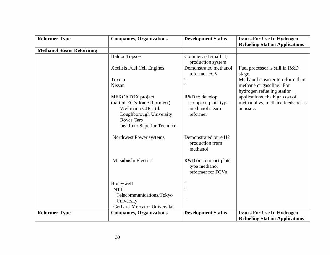
39
Reformer Type Companies, Organizations Development Status Issues For Use In HydrogenRefueling Station Applications
Methanol Steam ReformingHaldor Topsoe
Xcellsis Fuel Cell Engines
ToyotaNissan
MERCATOX project(part of EC’s Joule II project)
Wellmann CJB Ltd.Loughborough UniversityRover CarsInsitituto Superior Technico
Northwest Power systems
Mitsubushi Electric
Honeywell NTT
Telecommunications/TokyoUniversity
Gerhard-Mercator-Universitat
Commercial small H2
production systemDemonstrated methanol
reformer FCV““
R&D to developcompact, plate typemethanol steamreformer
Demonstrated pure H2production frommethanol
R&D on compact platetype methanolreformer for FCVs
““
“
Fuel processor is still in R&Dstage.Methanol is easier to reform thanmethane or gasoline. Forhydrogen refueling stationapplications, the high cost ofmethanol vs, methane feedstock isan issue.
Reformer Type Companies, Organizations Development Status Issues For Use In HydrogenRefueling Station Applications
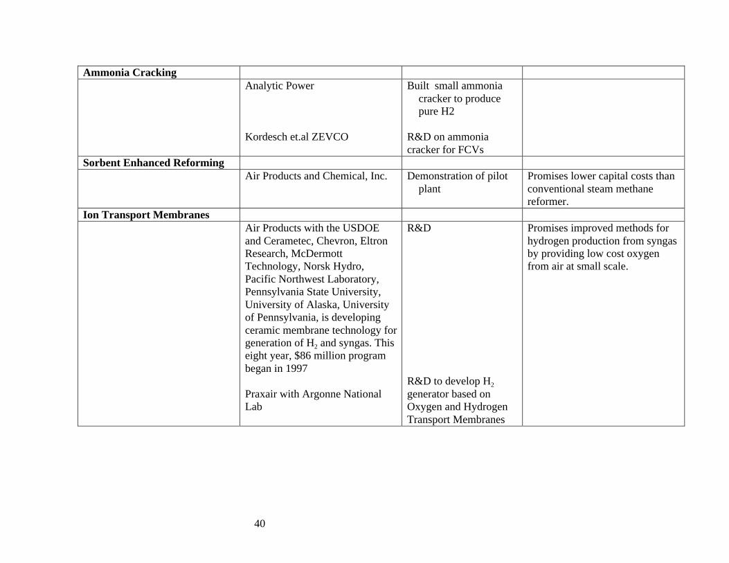
40
Ammonia CrackingAnalytic Power
Kordesch et.al ZEVCO
Built small ammoniacracker to producepure H2
R&D on ammoniacracker for FCVs
Sorbent Enhanced ReformingAir Products and Chemical, Inc. Demonstration of pilot
plantPromises lower capital costs thanconventional steam methanereformer.
Ion Transport MembranesAir Products with the USDOEand Cerametec, Chevron, EltronResearch, McDermottTechnology, Norsk Hydro,Pacific Northwest Laboratory,Pennsylvania State University,University of Alaska, Universityof Pennsylvania, is developingceramic membrane technology forgeneration of H2 and syngas. Thiseight year, $86 million programbegan in 1997
Praxair with Argonne NationalLab
R&D
R&D to develop H2
generator based onOxygen and HydrogenTransport Membranes
Promises improved methods forhydrogen production from syngasby providing low cost oxygenfrom air at small scale.

41
Reformer Type Companies, Organizations Development Status Issues For Use In HydrogenRefueling Station Applications
Catalytic Cracking of MethaneFlorida Solar Energy CenterGerhard-Mercator-Universitat
Basic science“
Catalyst must be regeneratedfrequently to remove carbon
Plasma ReformerMIT
INEEL
R&D
“

42

43
NEAR TERM GASEOUS H2 SUPPLY OPTIONSCENTRALIZED REFORMING
NGLH2
LH2
TRUCK DELIVERY
LH2H2 veh
COMP. H2 GASdewar
LH2 pump+vaporizer
dispenser
NG H2 H2 veh
compressorstorage
PIPELINE DELIVERY
COMP. H2 GAS
dispenser
(a)
(b)
reformer
NG H2 veh
COMP. H2 GAScompressor
storage
ONSITE REFORMINGdispenser(d)
ELECTRICITY
ONSITE ELECTROLYSIS(e)
CHEMICAL BY-PRODUCT HYDROGEN
H2 H2 veh
compressorstorage COMP. H2
GAS
dispenserRefinery or Chemical Plant
(c)

44
Figure 1.

45
Figure 2.
SOLAR or WIND ELECTROLYTIC HYDROGEN
H2 veh
COMP. H2 GAS
storagecompressor
electrolyzerPV Array
H2 via BIOMASS, COAL or MSW GASIFICATION
BIOMASS, COAL or MSW
H2 H2 veh
compressorstorage
H2 H2 veh
compressorstorage
storage
electrolyzer
Wind Turbine
LONG TERM HYDROGEN SUPPLY OPTIONS
H2 FROM HYDROCARBONS w/CO2 SEQUESTRATION
NG, BIOMASS or COAL
H2 H2 veh
compressorstorage
CO2
to underground

46

47
Figure 3.
0
5
10
15
20
25
30
Deliv
ere
d C
ost
of
H2
($/G
J)
LH
2 T
ruck D
elivery
Centr
al SM
R -
pip
eline d
eliv.
- lo
densit
y
Centr
al SM
R -
pip
eline d
eliv.
-hi densit
y
Onsi
te a
dv.
SM
R
Onsit
e a
dv.
ele
ctr
oly
sis
Delivered Cost of HydrogenTransportation Fuel ($/GJ)
LABOR
DISPENSER
LH2 TANK+PUMP
LIQUID HYDROGEN
ELECTRICITY
COMPRESSOR CAPITAL+O&M
STORAGE CYLINDERS
ELECTROLYZER CAPITAL+O&M
PIPELINE H2 T&D
CENTRAL H2 PRODUCTION
NATURAL GAS
REFORMER
NG costs $3/MBTU;off-peak power costs 3cents/kWh. Each refueling stationdispenses 1 million scfH2/day.

48
Figure 4.
0
200
400
600
800
$/c
ar
Centr
al SM
R -
LH2 T
ruck D
eliv.
Centr
al SM
R -
H2 P
ipeline D
eliv-l
o d
ensi
ty
Centr
al
SM
R -
pip
eline d
eliv-h
i densit
y
Onsi
te S
MR -
Adv.
Onsit
e E
lectr
oly
sis
- A
dv.
Capital Cost of H2Infrastructure ($/car)
Refueling Station
Delivery
Cntrl Comp.+Sto
Liquefaction
H2 Production
Each refuelingstation dispenses1 million scf H2per day, serving afleet of 9200 H2fuel cell cars
Central SMR plant produces160 million scf/day, servinga total fleet of 1.4 million H2Fuel cell cars. Low demand casehas 300 cars/sq.mi, highdemand has 3000 cars/sq.mi

49

50
Figure 5a.
CITY SCALE INFRASTRUCTURE
EARLY INFRASTRUCTURE Central H2 Production Plant
H2 to other users
Decentralized Production from NG
NG
and/orNG, Wastes or Coal
Bus or Car Fleets
Central H2 Production from NG, Coal, Biomass or Wastes, w/ H2 Distrib to Many Refuel Stations
If NG available Decentralized Production of H2 from NG at Refueling Stations
NG
or

51
Figure 5b.
HYDROGEN ENERGY ECONOMY W/CO2 SEQUESTRATION
CO2 to Sequestration Site
CO2 Sequestration
Central H2 Production from NG, Coal, Biomass or Wastes, w/ H2 Distrib to Many Refuel Stations
CITY 1
CITY 2
CITY 3

52

53
Figure 6.
SyngasH2, CO, CO2, CH4, H20
Steam
Natural Gas or Light Hydrocarbon
Heat
Pure H2
Compressor
Waste gases
Steam
Hydrogen Purification
Shift ReactorCO+H20->CO2+H2
Steam Reformer
H2 Storage
to H2 Users
SyngasH2, CO, CO2, CH4, H20
Oxygen or air
Pure H2
Compressor
Waste gases
Steam
Hydrogen Purification
Shift ReactorCO+H20->CO2+H2
Partial Oxidation
H2 Storage
to H2 Users
THERMOCHEMICAL HYDROGEN PRODUCTION METHODS
Natural Gas or Liquid Fuel
STEAM REFORMINGPARTIAL OXIDATION

54
Figure 7a
TOP VIEW
FLAME
FEEDCH4, STEAM
SYNGASH2, CO, CO2, CH4, H20TO SHIFT REACTOR
TUBES
CATALYST-FILLED
METHANE REFORMER DESIGN
12 m
REFORMERBURNER FUEL GAS
TYPICAL TUBE WALL MATERIALS: HIGH ALLOY STEELS: HK-40, IN 519
TYPICAL DIMENSIONS:WALL THICKNESS: 10-20 mm
SINGLE REFORMER TUBE
TYPICAL CATALYST MATERIALS:NICKEL ON ALUMINA SUPPORT
AIR
REFORMER BURNER FLUE GASES (TO HEAT RECOVERY BOILER)

55
Figure 7b
TOP VIEW
PRODUCT SYNGAS OUTLETH2, CO, CO2, CH4, H20(TO SHIFT REACTOR)
COMPACT, TUBULAR, SMALL SCALE STEAM METHANE REFORMER DESIGNED FOR FUEL CELL APPLICATIONS, WITH CONVECTIVE HEAT TRANSFER (Based on Haldor-Topsoe "Heat Exchange Reformer")
TYPICAL TUBE WALL MATERIALS: STAINLESS STEEL
FLAME
FEEDCH4, STEAM
FUEL GAS
REFORMER BURNER FLUE GASES (TO HEAT RECOVERY BOILER)
AIR
FIRST CATALYST BED
SECOND CATALYST BED
FLUE GAS FLOW CHANNELS
PRODUCT GAS FLOW FROM 1ST BED TO 2ND BED
REFORMER BURNER
7 m
FLUE GASES
PRODUCT GASES

56
Figure 7c. Plate Type Reformer
TO BE ADDED

57
Figure 7d. Membrane Reactor for Steam Reforming
TO BE ADDED
58
APPENDIX A. Hydrogen Refueling Station Projects
Increasingly, hydrogen refueling infrastructure demonstrations are conducted as part of hydrogen vehicle demonstrations. Alist of ongoing hydrogen refueling station projects is given in Table A.1. Over the next several years, small scale reformers ofvarious types will be tried.

59
Table A.1: Hydrogen Vehicle Refueling Station Demonstrations WorldwideSite/participants Year Type of Refueling SystemUniv. of California Riverside, CA 1995 PV Electrolysis supplying
hydrogen for IC enginepick-up truck
Xerox Park, Canoga, CAClean Air Now, Xerox
1995 PV Electrolysis supplyinghydrogen for IC engine cars
Humboldt State University,Schatz Energy CenterPalm Desert, CA
1997- PV Electrolysis supplyinghydrogen for IC engine cars
Ford Motor Company, Dearborn,Michigan
1998- Trucked in liquid H2
vaporized to provide highpressure gas
Chicago Transit Authority, Chicago, ILBallard Power Systems, Air Products
1998-2000 Trucked in liquid H2
vaporized to provide highpressure gas to three fuelcell buses
City of Las Vegas, NVAir Products, Plug Power
2000-2004 Plans include: Truckdelivered H2 and small scalereforming of natural gasproducing H2 and CNG/H2
blends for ICE vehiclesBC TransitVancouver, British ColumbiaBallard Power Systems, Stuart Energy
1998-2000 H2 is produced viaelectrolysis using off-peakpower for three fuel cellbuses
BC Hydro 2001 H2 refueling station basedon electrolysis underconstruction
Sunline Transit, Thousand Palms, CAHydrogen Burner Technology, CaliforniaAir Resources Board
1999- Production of H2 via smallscale partial oxidation ofnatural gas for H2 buses
California Fuel Cell Partnership 2001- Planned demonstration of

60
refueling systems for up to20 H2 fuel cell vehicles; Sacramento H2 station hastrucked in LH2 to supplyhigh pressure H2 gas tovehicles
AC Transit, California Late 2001 H2 refueling stationplanned for fuel cell buses

61
Table A.1: Hydrogen Vehicle Refueling Station Demonstrations Worldwide(continued)
Clean Urban Transport for Europe(CUTE) Project10 cities in Europe plus Perth, WesternAustralia
Planned2002-
Planned demonstration of30 fuel cell buses in 10European cities. Varioustypes of H2 supply will beimplemented includingsmall scale reformers
Global Environment Facility/UNDP 2002- Planned demonstration of30 fuel cell buses indeveloping country cities
MAN/Siemens Planned demonstration offuel cell buses
Munich Airport 1999 Liquid hydrogen refuelin gstation for airport buses andBMW cars
Daimler Chrysler 2001- Planned H2 fuel cell busdemonstrations
Reykavik, IcelandShell Hydrogen
2001 H2 refueling station basedon electrolysis using lowcost geothermal power
WE-NET Project, Japan 2001 2 H2 refueling stations:Electrolysis (Takamata)Steam Reforming (Osaka)

62
APPENDIX B.LIST OF RECENT PATENTS RELEVANT TO SMALL SCALE HYDROGEN PRODUCTION VIA REFORMING
Plate-type Reformers
Allam, R.J., Bassett, J.D., Abradro, J., amd P.L. DaPrato, “ Integrated plate-fin heat exchange reformation,” US Patent No.5,324,452, June 28, 1994. (Air Products and Chemicals)
Hamada, K., M. Mizusawa, and M. Koga, “Plate Reformer,” US Patent No. 5,609,834, March 11, 1997. (
Hsu, M. and E.D. Hoag, “ Thermally enhanced compact reformer,” US Patent No. 6,183,703, Feb.6, 2001. (Ztek)
LeSieur, R., “Compact Fuel Gas Assemblage,” US Patent No. 5,733,347, March 31, 1998. (International Fuel Cells)
Membrane reactor reformers
Minet, Ronald G. and T. Tsotsis, “Catalytic ceramic membrane steam/hydrocarbon reformer,” US Patent No. 4,981,676, Jan.1, 1991. (No corporate affiliation given)
Verrill, C.I., L.J. Chaney, K.E. Kneidel, R.A. McIlroy, and R.M. Privette, “Compact Multi-Fuel Steam Reformer,” US PatentNo. 5,938,800, August 17, 1999. (McDermott Technology, Inc.) steam reforming
Shirasaki, Y., M. Gondaira,Y. Ohta, et.al, “Hydrogen producing Apparatus,” US Patent No. 5,639,431, June 17, 1997. (TokyoGas Company, Mitsubishi Heavy Industry) steam reforming
J.Z. Galuszka, “Process for producing syngas and hydrogen from natural gas using a membrane reactor,” US patent No.5,637,259, June 10, 1997. (Natural Resources Canada). – partial oxidation reforming
D. Edlund and W.A. Pledger, “Steam reformer with Internal Hydrogen Purification,” US Patent No. 5,997,594, Dec. 7, 1999.(Northwest Power Systems LLC)

63
L.G. Marionowski and D.K. Fleming, “Hydrogen forming reaction process,” US Patent No. 4,810,485, March 7, 1989. (IGT)steam reforming with membrane separation of H2
D.P. Bloomfield and A.N. Rabe, “Electrochemical autothermal reformer,” US Patent No. 6,143,159, Nov. 7, 2000. (AnalyticPower).
Partial Oxidation Reformers
R. Woods, L. Greiner, and D. Moard, “Integrated Power Module,” US Patent No. 6,033,793, March 7, 2000. (describesHydrogen Burner Technology’s POX plus PSA system).
L.G. Clawson, W.L. Mitchell, J.M. Bentley, and J.H.J. Thijssen, “Method and apparatus for converting hydrocarbon fuel intohydrogen gas and carbon dioxide,” US Patent No. 6,126,908, October 3, 2000. (Arthur D. Little, Inc.)
R.J. Sanger, et.al “Apparatus for Providing a Pure Hydrogen Stream for Use with Fuel Cells,” US Patent No. 6,190,623, Feb.20, 2001. (UOP)
Ion Transport Membranes
S. Nataraj and S.L. Russek, “Synthesis gas Production by Ion Transport Membranes,” US patent No. 6,077,323, June 20, 2000.(Air Products and Chemicals, Inc.)
Gottzmann, C.F., R. Prasad, J.M. Schwartz, V.E. Bergsten et.al “Tube and shell reactor with oxygen selective ion transportceramic reaction tubes,” US Patent No. 6,139,810, Oct. 31, 2000. (Praxair, Standard Oil).
Kleefisch, M.S., C.A. Udovich, J.G. Masin, T.P. Kobylinski, “Membrane reactor hollow tube module with ceramic/metalinterfacial zone,” US Patent No. 5,935,533, August 10, 1999. (BP Amoco)
Abeles, B., R.B. Hall, M. Zhou, “Multi-layer membrane composites and their use in hydrocarbon partial oxidation,” US PatentNo. 5,846,641, Dec. 8, 1998. (Exxon)
B.M. Sheikh-Ali and G.E. Wnek, “Ion conducting membrane for fuel cell,” US patent No. 6,110,616, August 29, 2000. (Dais-Analytic)

64
Methanol Reformers
J. Meusinger, L. Haart, and U. Stimming, “Membrane reactor for producing CO and CO2 free hydrogen,” US Patent No.6,129,861, Oct. 10, 2000. (Forschungzentrum Julich GmbH)
R. Autenrieth et,al “Process for methanol reforming apparatus,” US Patent No. 6,074,770, June 13, 2000. (DBB Fuel CellEngines)
R. Kumar et.al “Fuel cell system for transportation applications,” Argonne National Laboratory, US Patent No. 5,248,566, Sept28, 1993. (ANL)
G. Bohm, et. al, “Process for obtaining a high hydrogen low carbon monoxide gas,” US Patent No. 5,904,913, May 18, 1999.