review on additive manufacturing of tooling for hot stamping · technologies is also required....
TRANSCRIPT

ORIGINAL ARTICLE
Review on additive manufacturing of tooling for hot stamping
Dimitrios Chantzis1 & Xiaochuan Liu1& Denis J. Politis2 & Omer El Fakir1 & Teun Yee Chua1 & Zhusheng Shi1 &
Liliang Wang1
Received: 13 February 2020 /Accepted: 8 June 2020# The Author(s) 2020
AbstractSustainability is a key factor in an automotive OEMs’ business strategy. Vehicle electrification in particular has receivedincreased attention, and major manufacturers have already undertaken significant investments in this area. However, in orderto fully confront the sustainability challenge in the automotive industry, lightweight design in additional to alternative propulsiontechnologies is also required. Vehicle weight is closely correlated with fuel consumption and range for internal combustion andelectrified vehicles, respectively, and therefore, weight reduction is a primary objective. Over the past decades, advanced steeland aluminium-forming technologies have seen considerable development, resulting in significant weight reduction of vehiclecomponents. Hot stamping is one of the most established processes for advanced steel and aluminium alloys. The process offerslow-forming loads and high formability as well as parts with high strength and minimal springback. However, the high temper-atures of the formed materials over numerous cycles and the significant cooling required to ensure desirable component prop-erties necessitate advanced tooling designs. Traditionally, casting andmachining are used to manufacture tools; although in recentyears, additive manufacturing has gained significant interest due to the design freedom offered. In this paper, a comprehensivereview is performed for the state-of-the-art hot-forming tooling designs in addition to identifying the future direction of AdditiveManufactured (AM) tools. Specifically, material properties of widely used tooling materials are first reviewed and selectioncriteria are proposed which can be used for the transition to AM tools. Moreover, key variables affecting the success of hotstamping, for example cooling rate of the component, are reviewed with the various approaches analysed by analytical andnumerical techniques. Finally, a number of future directions for adopting additive manufacturing in the production of hotstamping tools are proposed, based on a thorough analysis of the literature.
Keywords AdditiveManufacturing . Design for AdditiveManufacturing . Hot stamping . Die design
1 Introduction
Globally, manufacturing is regarded as one of the primarysources of wealth, and yet, the large amount of energy usedfor industrial operations, in combination with the increasingdemand for goods, causes significant environmental repercus-sions. Until recently, the performance of a production systemhas been evaluated by taking into consideration four mainattributes as follows: cost, time, quality and flexibility [1].However, global megatrends [2] such as climate change are
moving the manufacturing community towards the consider-ation of sustainability. As a result, sustainability must be con-sidered in all stages of the manufacturing decision-makingprocess [3]. The automotive industry is a major sectoradapting to this new framework, which consists ofgovernment-regulated emission standards such as Euro 6 forEurope or CAFE for the USA, or even more radical politicalrulings such as the UK’s decision to ban all petrol and dieselvehicles by 2040 [4]. The answer of the automotive industryto this challenge is electrification, and major automotiveOEMs have already announced plans for full electric orplug-in hybrid vehicles [5].
However, vehicle sustainability should not be addressed byfocussing on electrification alone. Another key element inefficiency is lightweight design, which can reduce the envi-ronmental footprint of both internal combustion (IC) and elec-trified vehicles. Vehicle weight closely correlates with fuelconsumption and range, for IC and electrified vehicles,
* Liliang [email protected]
1 Department of Mechanical Engineering, Imperial College London,Exhibition Road, London SW7 2AZ, UK
2 Department of Mechanical and Manufacturing Engineering,University of Cyprus, 1678 Nicosia, Cyprus
https://doi.org/10.1007/s00170-020-05622-1
/ Published online: 30 June 2020
The International Journal of Advanced Manufacturing Technology (2020) 109:87–107

respectively, and thus its reduction is effective regardless ofvehicle propulsion technology. The objective of lightweightdesign is to minimise dead weight of a construction withoutimpinging on function, safety or useful life [6].
Over the past decades, advanced steel manufacturing tech-nologies have seen considerable development, resulting in thesignificant reduction of vehicle component weight through theuse of advanced steel alloys, such as high-strength steel(HSS), advanced high-strength steel (AHSS) and ultra-high-strength steel (UHSS) [7]. In the automotive industry, ultra-high-strength steels can be considered a relatively ‘low cost’lightweight material option compared with aluminium alloys,and OEMs have extensive knowledge regarding their manu-facturability. Moreover, their capability to absorb impact en-ergy in a collision as well as their adequate formability andjoining capability make steel alloys a popular choice withautomotive manufacturers. On the other hand, aluminiumhas attracted significant attention due to an improvedstrength-to-weight ratio compared with steel and unique cor-rosion behaviour [8]. A characteristic example of the in-creased adoption of aluminium is in North American OEMvehicles, which has seen an increase of 27% between the years2012 and 2015. The increase stems from an equal combina-tion of higher vehicle production and increased aluminiumcontent per vehicle (Ducker [9]). According to the literature[10], aluminium will comprise of more than 75% of pickuptruck body parts, 24% of large sedans, 22% of SUVs and 18%of minivan body and closure components by 2025.
Hot stamping is considered one of the main forming pro-cesses for manufacturing advanced steel and aluminium alloysheet components [11, 12]. The number of hot stamping partsis increasing in a BiW with most of them used in the crash-related zones. These zones must resist intrusion and maintaintheir integrity. Numerous studies have been published regard-ing hot stamping of roof rail [13], door impact beam [14] or B-pillar inner [15, 16]. On the other hand, cold forming is mainlyused with mild steel which is mainly used for non-criticalsafety parts such as closures [17]. Hot stamping processeshave increased complexity compared with cold stamping, assuccessive processes such as quenching are crucial to the con-trol of cooling rate and subsequent post-form strength [18].The cooling rate is determined largely by the quantity of ther-mal energy transferred from the deformed component to thetool cooling system.
Press tools are typically designed with internal coolingchannels and manufactured by conventional machining pro-cesses such as drilling, in order to achieve the desirablecooling rates. A significant challenge to existing cooling chan-nel production methods is that the channels are unable followan equidistant profile to the tool surface, resulting in inconsis-tent quench rates throughout the component [19]. In addition,large press tools are manufactured by segmenting a single toolinto multiple pieces, which are individually machined and
subsequently assembled. Tool segmentation is also often re-quired due to limitations of cooling channel drilling technol-ogies [20].
To this end, additive manufacturing (AM) offers significantadvantages, as opposed to conventional subtractive technolo-gies [21]. These include the fabrication of complex geome-tries, material savings, design flexibility and reduced toolingcosts [22]. The most evident realisation of these advantageshas been in plastic injection moulding, where steel tools forfinal production, have been fabricated using additive tech-niques in several works [23–28]. However, the adoption ofAM techniques for direct hot stamping tooling has seen lim-ited progress.
The authors acknowledge the significant potential of theAM on the design and manufacture of hot stamping tooling.Thus, the aim of this article is to review currently availableliterature in the area that AM and hot stamping tooling inter-sect. Section 2 provides an overview of hot stamping and itsprocess principles. Section 3 reviews recently published stud-ies onAdditivelyManufactured hot stamping dies. Section 3.1investigates design approaches of cooling systems for hotstamping dies and how these can be applied for AM, whilein Section 3.2 simulation models are reviewed and sugges-tions are proposed for their use in AM. Then, Section 3.3reviews the thermo-mechanical properties of well-established hot stamping tooling materials and identifies min-imum threshold criteria that can be used for the transition toAdditively Manufactured materials. Finally, summary andconcluding remarks of the study are provided as well as theauthors’ outlook for AM in hot stamping tooling.
2 Hot stamping of ultra-high-strength steelsand aluminium alloys
2.1 Hot stamping of ultra-high-strength steels
Hot stamping processes for ultra-high-strength steels currentlyexist in the following two main variants: direct and indirecthot stamping processes (Fig. 1). In a direct hot stamping pro-cess, the blank is heated in a furnace, transferred to the pressand subsequently formed and quenched in the closed tool. Anindirect hot stamping process is characterised by the use of anearly complete cold pre-formed part which is subjected onlyto a quenching and calibration operation in the press afteraustenitisation [30].
A crucial requirement in the hot stamping of steels is thetransformation of the material microstructure from austenite tomartensite to achieve the desirable post-form mechanicalproperties. This can be achieved through careful thermal con-trol at each process stage. During heating, the temperaturemust be above the re-crystallisation temperature in order forthe microstructure to achieve austenisation. Moreover, the
88 Int J Adv Manuf Technol (2020) 109:87–107

blank temperature must be homogeneous, which is a pre-condition for the desired fully martensitic transformation[31]. During the subsequent hot blank transfer operation tothe forming tool, the temperature decreases rapidly due to heatloss to the surrounding environment. Lengthy transfer timesmay result in microstructural transformation to bainite andferrite, and therefore, it is crucial to place the blank in thedie at a temperature above 730 °C. The final operation is toform the blank inside the die and simultaneously quench. Thecold die acts as a heat sink to the hot blank during quenching,enabling the hot blanks microstructure to be transformed fromaustenite to martensite. However, this phase change is realisedonly when the cooling/quenching rate is above a critical value,which is alloy-dependent. If the cooling rate is below thisvalue, the microstructure of the final part will consist of bainiteor ferrite phases, which will affect the final mechanical prop-erties. CCT diagrams are used to represent the types of phasechanges that will occur in a material as it is cooled at differentrates. In Fig. 2, the CCT diagram of 22MnB5 is shown.Studies regarding this material have concluded that the criticalcooling rate to achieve a full martensite transformation is 30°C/s [33–36].
Since the cooling of the blank occurs within the dies, hotstamping die design is critical to the cooling performance anddirectly affects productivity. It has been found that quenchingtime accounts for up to 30% of the total process cycle time [37].
2.2 Hot stamping of high-strength aluminium alloys
Conventional forming of aluminium alloys encounters the fol-lowing two major issues: (i) the low formability of aluminium
Fig. 2 CCT diagram of 22MnB5 [32]Fig. 3 CCP diagrams for a 6082 aluminium alloys [58] and b 7075aluminium alloys [57].
Fig. 1 Existing hot stampingtechnologies for UHSS. a Directhot stamping, b indirect hotstamping [29]
89Int J Adv Manuf Technol (2020) 109:87–107

alloys at room temperature which significantly limits theirapplication to the forming of complex-shaped components[38] and (ii) the low stiffness of aluminium alloys at roomtemperature which causes high springback of the formed com-ponents [39]. Solution heat treatment, cold die forming and in-die quenching (HFQ) was developed as a promising hotstamping technology to address these two issues [40–42].During an HFQ forming process, an aluminium alloy blankis first heated to its solution heat treatment temperature (SHT)followed by a specific period of soaking, in order to fullydissolve alloying elements and/or precipitates into the materialmatrix, resulting in high formability of the aluminium alloy.After the heat treatment, the hot blank is transferred to a pressmachine and then stamped into the desired shape by formingtools at room temperature. Simultaneously, the hot blank isquenched at a sufficiently high-cooling rate to achieve a su-persaturated solid solution state (SSSS). Consequently, pre-cipitates are uniformly generated and distributed within thealuminium matrix during the subsequent artificial ageing,reaching high post-form strength of the formed component.Due to these pronounced benefits, HFQ was patented globally[43, 44] and commercialised for automotive applications [45].
In recent years, Fast light Alloy Stamping Technology(FAST) was developed and patented as a novel hot stampingprocess, not only increasing the formability of aluminium al-loys and decreasing springback but also significantly reducingcycle time [46, 47]. During such a forming process, an alu-minium alloy blank is heated to an elevated temperature at anultra-fast heating rate, in order to enhance the ductility of thematerial while maintaining its microstructure. Subsequently,the hot blank is transferred to a press machine, and simulta-neously deformed and quenched by cold forming tools at ahigh cooling rate. Due to minor changes to the microstructure,the artificial ageing period is dramatically reduced to achievethe desired post-form strength. The elimination of lengthyheating, soaking and ageing periods is beneficial to the reduc-tion of cycle time. Furthermore, the processing parameters,such as temperature, heating rate, transfer time and coolingrate, could be customised to satisfy customer requirementsfor the post-form mechanical properties of the formed compo-nents [48–50].
Considering these advantages, hot stamping of aluminiumalloys has been studied by numerous researchers, under theprism of identifying optimum processing windows to realisecustomer requirements. In the study byHarrison et al. [51], thetransfer time of a hot blank from a furnace to a press machinewas reduced and precisely controlled by using a robotic arm toensure that a SSSS state for AA7075 could be achieved afterquenching. The stamping speed and blank holding force wereoptimised to reduce wrinkling and/or fracture of anti-collisionside beamsmade fromAA6111, as stated in the study by Zhouet al. [52]. The application of lubricants is another efficientmethod to avoid crack formation in formed components [53,
54]. Additionally, some researchers have employed dedicatedequipment in the hot stamping of aluminium alloys to realisedesirable processing windows. For instance, a servo motorwas applied in the study by Song et al. [55], to enable for amore uniform distribution of temperature and strain inAA7075 sheets. Resistance heating equipment was alsoemployed by Maeno et al. [56] to shorten the heat treatmentof aluminium alloys.
Despite the differences between these processing windows,all forming processes have the critical requirement ofquenching the aluminium alloys within cold forming tools.By evaluating the continuous cooling precipitation (CCP) di-agram of aluminium alloys, it can be found that the coolingcurve intersects the regions where coarse precipices (e.g. βand β' for 6XXX alloy) are generated. This results in second-ary particles being precipitated out and consuming alloyingelements which would lead to a decrease in the post-formmechanical strength. Therefore, critical cooling rates for alu-minium alloys must be achieved during quenching to avoidthis phenomenon [57, 58]. As a heat transfer medium, toolssignificantly affect the cooling rate of aluminium alloys, andtherefore the selection of tool materials and designs is of greatimportance in order to achieve the critical cooling rate [53,54].
It is well understood that hot stamping of both high-strength steels and aluminium alloys is a complex process thatrequires precise control of thermomechanical phenomena.However, while the majority of studies focus on the materialproperties of the final formed component, the significance ofthe applied tooling must also be emphasised [59].
3 Additive manufacturing of hot stampingdies
The manufacture of hot stamping dies with internal coolingchannels is a challenging task due to limitations in conven-tional processes. Currently, there are three methods ofmanufacturing internal cooling channels for hot stamping dies[60] as shown in Fig. 3. The first is the conventional drillingmethod. This method, although most cost effective [61], has aprofound disadvantage. Drilling can only produce straight linebores and cooling channels which are unable to maintain anequidistance from a complex 3D tool surface geometry.Consequently, “hot spots” are obtained which are essentiallyareas on a final component that have been cooled at differentrates compared with the rest of the component and inherentlyexhibit varied mechanical properties. The second method in-volves the segmentation of the die into two parts; the shell andthe core, with the cooling channels divided between them.Although this approach increases the design flexibility, it isassociated with increased cost and material waste. Moreover,the sealing between the two parts is a significant challenge
90 Int J Adv Manuf Technol (2020) 109:87–107

which contributes to its reduced popularity. The final methodinvolves producing the die through casting and pre-fixing thecooling channels inside the casting mould. However, fixingthe cooling channels is not a simple task, and there is thepossibility of the cooling channels melting during the castingof the die.Moreover, casting a die necessitates additional post-processing that it is not required by the other two methods.The manufacturing of hot stamping dies is typically associatedwith other research areas such as high performance cutting ofhot work steels [62–64]. However, the review of such studiesis outside the scope of this paper. Fig. 4
There are strong indications that AM can be a disruptivetechnology for hot stamping tools. The design flexibility of-fered can aid designers to realise concepts that are currentlyunachievable using conventional manufacturing processes.Moreover, in the authors’ opinion, metal-forming tooling isthe only area that can fully exploit the benefits of AM pro-cesses in the short term as high production volumes are notrequired for such applications. In the automotive industry, themanufacturing of a die usually takes 21 weeks [65], and there-fore even with current deposition rates, AM technologies canbe considered as a viable alternative. In this section, small-scale case studies are presented addressing the application ofAM. Although there are several published studies regardingthe application of AM to tooling, this work focuses specifical-ly on studies addressing hot stamping and does not includeresults from other manufacturing sectors such as injectionmoulding.
Cortina et al. [66] investigated the design of conformalcooling ducts, which were additively manufactured on aCR7V-L hot work steel substrate and then post-processedwithmilling. AISI H13 and AISI 316L laser claddings were used as
the filler material for the manufacture of the cooling channels(Fig. 5).
The mechanical as well as thermal performance of thespecimen shown in Fig. 5 was evaluated, and it was concludedthat laser cladding is a viable alternative manufacturing pro-cess. In Fig. 6, the thermal performance of the two coolingchannels is shown and it can be observed that they are almostidentical.
The authors subsequently transferred the proposedmanufacturing approach to a complex geometry (Fig. 7) andtheir cooling effectiveness was compared with conventionalmanufacturing. The results showed that a more homogeneoustemperature distribution could be achieved with AMedchannels.
In addition, the study by Muller et al. [37] has alsohighlighted the benefits of additively manufacturing coolingchannels. It was determined that the main benefit of complexcooling channels following the profile of the parts was theradically reduced quenching time during hot stamping pro-cesses, which accounts for 30% of the cycle time. The coolingsystem was redesigned through simulations, and the key inputparameters were the compression force, workpiece tempera-ture, coolant temperature, flow rate and internal surface rough-ness of the cooling channels. The resulting improvement inboth the temperature gradient and temperature on the die’sworking surface was significant (Fig. 8).
The performances of the cooling systems were evaluatedby simulating the temperature distribution on the final com-ponent. It is clear that the most critical area is in the die’sdeepest cavity, which conventional cooling channels couldnot reach due to manufacturing limitations in following thegeometric profile of the part. The AMed cooling channels
Fig. 4 Different manufacturingmethods for internal coolingchannels (adapted from [60])
91Int J Adv Manuf Technol (2020) 109:87–107

were able to achieve a temperature in this area that was almost50% lower than with conventional cooling channels (Fig. 9).
In addition to simulation work, the authors conducted ex-perimental work that verified that the additively manufacturedtools reduced the quenching time by 50%.
The studies of Cortina et al. [66] and Muller et al. [37] arethe only studies that have investigated the potential of additivemanufacturing for hot stamping processes of metallic parts.From a review of the literature, the majority of publishedpapers have focused on the investigation of AM in injectionmoulding of plastic parts [23–28]. As the focus of this reviewis on AM for metal hot stamping, injection moulding studiesare not taken into consideration due to the variations of ther-mal and mechanical loads.
3.1 Design of cooling system for hot stamping dies
Quenching is one of the main bottlenecks to the overall hotstamping cycle time [67] withMuller et al. [37] estimating thisprocess to account for 30% of the total production process.Quenching is achieved through a medium which flowsthrough the cooling system and acts as a heat sink extractingheat from the blank. It is clear that a cooling system withtangential cooling channels to the working surface of the die
and to each other would be ideal from a thermodynamic pointof view. However, this would deteriorate the mechanical per-formance of the die and would compromise its structural in-tegrity. Moreover, the diameter of a cooling channel plays asignificant role in the thermal performance of the die. A great-er volume of cooling medium can flow through a large diam-eter compared with a smaller one. However, there is a limit onthe cooling channel diameter as significant removal of mate-rial can compromise die integrity.
Therefore, it is clear that the design of a cooling system fora hot stamping die is a multi-objective optimisation task.Ideally, conformal cooling design is preferred; however, dueto manufacturing constraints, they may be prohibitively ex-pensive. Hence, straight circular drilled cooling channels arethe most practical choice in industry thus far.
3.1.1 Design for additive manufacturing of hot stamping diecooling systems
The almost infinite design flexibility that AM technologiesoffer compared with existing die manufacturing technologiesenables the manufacturing of optimised cooling channels forhot stamping dies. However, due to the additive nature ofthese processes, there are several design constraints that the
Fig. 6 Measurements from athermal camera (left, coolant isoff; right, coolant is on) [66]
Fig. 5 a Initial CR7V-L substratewith one drilled channel andprepared machined surfaces forcladding. b Finished sample withone drilled and one additivelymanufactured cooling channel[66]
92 Int J Adv Manuf Technol (2020) 109:87–107

designer must consider. For instance, components which aredesigned with overhanging features may require sacrificialsupports to build them successfully. These supports increasebuild time, consume extra powder material and require addi-tional post-processing for their removal. Therefore, in the con-text of AM hot stamping die cooling systems, a design for AM(DfAM) approach is critical for the production, performanceand cost effectiveness of additive manufacture.
Lim et al. [68] has provided calculations for the averagetemperature of the tool surface by using an analytical modelbased on the energy balance principle and a specific cycletime. Based on the average temperature, the diameter of thecooling channels was determined and a recommended rangeof cooling diameters for different blank thicknesses was pro-vided as shown in Table 1.
It is observed that for blank thicknesses up to 2 mm, whichis the typical blank thickness used in hot stamping, a coolingchannel of 8–10 mm diameter is recommended. Mazur et al.[69] investigated the AM manufacturability of conformalcooling channels and concluded that a circular profile sectionchannel of 2–8 mm would be compromised in cylindricalaccuracy by 6% due to build errors where arc sections ap-proach the horizontal. To overcome this issue, several studiesproposed a design for cooling channels with easy to buildsupportive internal lattice structures [24, 70, 71]. The conceptwas evaluated and the results showed that indeed the proposed
design reduces cooling time. The reason is that the latticestructures were found to increase heat transfer due to increasedinterfacial surface areas and fluid vorticity. Although the re-sults are positive, the proposed approach has been experimen-tally validated only in the case of a straight cooling channel[71] (Fig. 10). In the case of conformal cooling channelswhere the centre line of a cooling channel is complex, theinternal lattices may severely affect the coolant flow and con-sequently decrease the quenching effect.
Another approach to overcome the issue of circular accu-racy of the cooling channels is to use self-supported crosssections such as diamond shaped or teardrop shaped.However, the designer should always consider the orientationof the part inside the chamber as this is the main parameter thatcharacterises whether a structure is self-supported or not. Forinstance, a teardrop shaped-cooling channel is self-supportedif the circular section is oriented towards the base plate (Fig.11) but is not when rotated 180 degrees.
Orientation can impact other aspects such as surface qualityof the part or build time and any effort to develop a holisticoptimisation strategy will give contradictory results. For in-stance, high volume of support structures will be needed if adie is horizontally placed. However, in this case the build timewill be reduced since the number of layers will be fewer com-pared with when the part is placed vertically. Usually, pro-posed methods for orientation optimisation are focussing on
Fig. 8 a Conventional drilled cooling channels (max temperature in the tool 191 °C), b optimized cooling channels (max temperature 81 °C), ccomparison of the temperature gradient in the conventional and optimized cooling system [37]
Fig. 7 a Complex geometry with conformal cooling channels. b Temperature distribution with conformal cooling channels. c Temperature distributionwith conventional channels [66]
93Int J Adv Manuf Technol (2020) 109:87–107

a specific objective. There are part orientation optimisationmethods for minimising the surface roughness of the final part[72, 73], increasing mechanical properties such as strength toa specific direction [74, 75], and reducing support structuresor even minimizing build time [73, 76–78]. In the case of hotstamping dies, the key objective should be the manufacturabil-ity of cooling channels without support structures. Other as-pects such as surface roughness are not crucial as an additivelymanufactured die will be post-processed. Post-processing isnecessary for AM components as the typical surface rough-ness values for SLM are 10–15 μm, whereas for EBM are 20–35 μm [79], which are in excess of the 8 μm required byindustry for hot stamping dies. However, a potential post-processing of the cooling channels might not be possible dueto difficulty in accessing the required locations. Moreover, anadditional challenge, which derives from the limited buildvolumes of current additive manufacturing machines, is thata hot stamping die for industrial applications cannot be printedin one part. Therefore, the designer must develop a segmen-tation strategy in order to utilise as much of the availableprinting volume as possible.
3.2 Simulation approaches for the design of hotstamping die cooling systems
A short quenching time is dependent, alongside other param-eters, on the design of the cooling system of the die. There arethree main design parameters that need to be identified for thedesign of a die’s cooling system; the distance of the coolingchannel from the working surface of the die (dsp), the distance
between two neighbouring cooling channels (dpp) and thediameter of the cooling channel (D) [80, 81].
Both analytical and computational simulation models havebeen used in the literature for the design of a hot stamping die.The majority of analytical models use the energy balanceprinciple as well as heat transfer theory and can provide arapid calculation although of reduced accuracy for dsp, dppand D. For increased accuracy, many researchers use finiteelement analysis (FEA)methods to optimally select the designvariables for a hot stamping die cooling system. A summaryof key modelling methodologies and respective studies aresummarised in Table 2.
The main issue of the aforementioned models is that theyhave been developed for hot stamping dies manufactured withconventional processes and materials. Computational and an-alytical models need to be revised to take into account someinherent characteristics of AM processes.
AM-produced components encounter a complex cyclicthermal history consisting of directional heat extraction, re-peated melting and rapid solidification, which creates aniso-tropic and heterogeneous microstructures that differ from me-tallic parts manufactured via conventional methods.Moreover, AM defects such as pores and lack of fusion layers
Fig. 9 Temperature distributionin the final part for a conventionalcooling channels (temperature inthe deepest cavity 335 °C) and bAMed cooling channels(temperature in the deepest cavity177 °C) [37]
Fig. 10 Proposed concept of additively manufactured cooling channels[71]
Table 1 Cooling channel diameter guideline based on blank thickness
Blank thickness, t, (mm) Cooling channel diameter, d, (mm)
t ≤ 2 8 ≤ d ≤ 10
2 ≤ t ≤ 4 10 ≤ d ≤ 12
4 ≤ t ≤ 6 12 ≤ d ≤ 14
94 Int J Adv Manuf Technol (2020) 109:87–107

would induce anisotropic and heterogeneous properties suchas thermal conductivity to the final part. Furthermore, thecooling channels in an additively manufactured die cannotbe circular due to the overhang issue discussed previously.Thus, analytical models should be revisited and adjustedaccordingly.
Finally, with the design flexibility that AM processes offer,hot stamping dies with improved thermal performance can beproduced by integrating lattice structures to the main body ofthe die. Lattice structures can be used to insulate die sections
in proximity to the cooling channels of the die, reducing ther-mal mass and thus improving quenching efficiency. Severalresearchers have investigated the effect of lattice structures onthe thermal conductivity of hot stamping dies. Cheng et al.[88] developed an analytical model which predicts the ther-mal conductivity of a BCC lattice core sandwich structure.The model was validated experimentally although applyinganalytical methods to predict heat dissipation within a die withlattice structures is impractical and becomes unfeasible as thecomplexity of lattice topology increases. Therefore, the FEA
Table 2 Key modelling studieson hot stamping cooling systems Authors Modelling methodology Key remarks
[82] Analytical model considering:
i. Thermal conductivity of diematerial
ii. Velocity and temperature ofcooling medium
The study concluded that shorter cooling times can be attainedby placing the cooling channels closer to each other andcloser to the die working surface
[81]
[80]
Analytical model consideringstamping force
Most influential factor on cooling effectiveness is dsp, followedby dpp and D
[83] Effect of water velocity in thechannel on the die temperature
As the water velocity in a cooling system increased, thetemperature of the die rapidly decreased because of theturbulent flow state. However, there is a limit to this effect,where a velocity in excess of 3.5 m/s causes no significanteffect on the die temperature
[84] Analytical model considering onlyheat transfer phenomena
Equations for calculation of D and dsp
[85] FEA method The dimensions of the flume affect the water velocity andconsequently the flow uniformity. The relationship betweenthe flow field and flume width is that the wider the flume,the better the flow uniformity in the cooling channels. Onthe other hand, the flume height and flow field relationshipare not straightforward and follow a quadratic curvewith themaximum flow uniformity being achieved at a specificflume height
[86] FEA method coupled withevolutionary algorithm
In some cases, cooling channels with smaller diameters can bemore effective than larger ones because they can bepositioned closer to the stamping surface withoutcompromising the integrity of the tooling
[87] FEA method Use of segmented FEA models which reflect the geometricfeatures of the component. The proposed method reducescomputational time by 92.6%
Fig. 11 Effect of build directionon printability of a design feature
95Int J Adv Manuf Technol (2020) 109:87–107

analysis method is utilised in order to increase modelling ac-curacy. In the numerical analysis of parts with lattice struc-tures, two different approaches can be distinguished, namelythe micro-scale and the macro-scale approach. In the first ap-proach, the exact lattice structure’s geometry is modelled.However, this approach has an impact on the computationalcost of the analysis, making it challenging even for moderncomputers, since the geometry is complex. On the other hand,as the lattice geometry is periodic, each cell can be modelledas a volume of a homogenous material resulting in a macro-scale analysis and therefore reducing computational cost. Thenew homogenous material must have mechanical propertiesthat will give the same response as the lattice cell. Theseproperties are called effective material properties and can beeither isotropic or orthotropic, depending on the lattice celltopology and dimensional parameters. Finding these proper-ties requires the use of a technique known as “homogeniza-tion” which has been applied to other areas successfully [89].Conclusively, the existing models, both analytical and com-putational, can act as a basis for the development of coolingsystems. However, the models must be revised to acknowl-edge the anisotropic nature of AMed materials and beenriched by taking into account the new design features, suchas cellular structures which can be manufactured by AM.
3.2.1 Topology optimisation
The unique capabilities of AM technologies allow innovativedesign approaches that challenge traditional guidelines of sev-eral major industries including the hot stamping tooling sector.Among these approaches, topology optimisation (TO) (Fig.12) offers the greatest design flexibility, as it allows for mate-rial distribution in terms of physics requirements, offering thepotential to create novel and complex parts with high perfor-mance and reducing material cost. TO generates a freeformgeometry which is usually optimised against a specific objec-tive, for example stiffness. However, the objectives of TO canbe more than non-linear optimisation, which gives the opti-mum combination of two performance criteria such as thermaland mechanical. The concept of thermomechanical topologyoptimisation has been successfully applied in injection mould-ing and electronics. In the case of injection moulding, resultshave shown a reduction of cooling time by 70% withoutcompromising the structural integrity of the mould [91]. In
the case of hot stamping, there are limited research studiesthat investigate the benefits of thermomechanical topologyoptimisation. Another use of TO can be the design ofoverhang-free components for AM. A simple way to achievethe overhang-free design is through post-processing of theoptimised geometry. For instance, Leary et al. [92] addedmaterials to the topology optimisation resulting in the removalof overhang-free violations, which is effective even thoughthe optimisation achieved by the TO process is compromised.A more structured approach was proposed by [93] in whichthe structural boundaries of the topology optimised geometryare measured and the support-required overhang segments arepenalised.
TO can be extremely useful in hot stamping die design as itcan generate a geometry which quenches the blank optimallyand simultaneously generates overhang free geometries.Another important benefit is that topology-optimised dies re-quire less material to be printed than fully solid ones. As aresult, printing time can be reduced. However, to the authors’knowledge there are no available studies applying TO to hotstamping die design. It would be useful at this point to high-light that the thermal criterion for hot stamping dies shouldderive from the blank quenching rate rather than the temper-ature profile of the die. The reason is that the required criticalcooling rate differs depending on material and can range from30 K/s for boron steel to up to 100 K/s for AA7075-T6.
3.3 Material properties for additively manufacturedhot stamping dies
Bulk materials for hot stamping dies require a unique combi-nation of properties. They must exhibit high tensile strength,hardness and toughness values as well as good corrosion re-sistance. Additionally, the die material must exhibit a lowthermal expansion coefficient and high thermal conductivity.It is common for the die material to be selected depending onthe specific part to be formed. For instance, a die material ofparticularly high thermal conductivity is preferable when hotstamping relatively large part geometry, of relatively thickgauge, but of simple complexity and limited forming depth.On the other hand, a die material of high hardness is preferablewhen hot stamping complex part geometry with large formingdepth, which generates high friction against the tools.Naganathan and Penter [94] outlined the most important bulk
Fig. 12 Topology optimised geometries with various self-supporting angles (a 26.6 deg, b 45 deg, c 63.4 deg) Gaynor and Guest, [90]
96 Int J Adv Manuf Technol (2020) 109:87–107

material properties for a hot stamping die, which are strength,hardness, impact toughness and thermal conductivity.Moreover, hot stamping is a process with cyclic thermal pro-file and since the aforementioned properties are temperature-dependent, the die must perform sufficiently in the operatingtemperature range. For example, UHSS stamping die temper-atures may reach 300–400 °C [95], whereas for aluminiumstamping, the die can reach up to 180 °C [96]. Temperature-dependent values of tensile strength, hardness, impact tough-ness and thermal conductivity of commonly used die materialsare presented in Table 3. The empty cells reflect the lack ofpublished data for material properties of hot work tool steels atelevated temperatures.
In the literature, there are no clear material selection criteriafor hot stamping dies, with most studies focussing on theproperties of the final components manufactured by hotstamping instead. The study by Ye et al. [109] has addressedmany aspects of material selection, although the study is lim-ited in that thermal conductivity is not considered an “index”for hot stamping die material selection.
In Fig. 13, the critical bulk material properties, as have beenoutlined, are graphically mapped for well-established hotworked steels. Commercially, these grades of hot work steelscan be found with slight variations in mechanical propertiesdue to different heat treatment strategies. As can be seen from
Fig. 13, there is no singular material that demonstrates excel-lent performance for every material property. However, a ma-terial with minimum 18 J (Charpy V notch test) of impact
Table 3 Tensile strength, hardness and toughness values as a function of temperature of hot work tool steels
Material KPI Steel Grade Operating temperature Reference
25 °C 100 °C 200 °C 300 °C 400 °C 500 °C 600 °C 700 °C
Tensile Strength(MPa)
H11 1505 - - - 1187 1035 - - [97]
H13 1990 - 1480 - 1360 1050 - 500 [98]
1.2367 1457 - - 1264 1184 985 - - [99]
CR7V-L 1600 - 1400 1350 1200 1150 800 - [100]
HTCS-130 1314 - - - 1200 - - - [101]
Hardness(HRC)
H11 56 52 48 45 42 38 35 - [102]
H13 50 46 45 43 41 37 30 - [98]
1.2367 55 - 54 52 51 46 38 - [103]
CR7V-L 56 - - - - - - - [100]
HTCS-130 50 - - - - - - - [104]
Toughness(J)
H11 18 - - - - - - - [102]
H13 25 28 36 40 42 43 41 - [97] [98]
1.2367 23 - - - - - - - (P.[97])
CR7V-L 56 - - - - - - - [100]
HTCS-130 28.5 - - - - - 47 - [105]
Thermal Conductivity(W/mK)
H11 - 26.8 - 27 27.3 - 29.3 - [106]
H13 22.7 25.5 26.3 26.2 26.7 28.0 29.1 27.3 [107] [98]
1.2367 27.0 28.0 30.0 29.0 28.0 27.0 - - [108]
CR7V-L 24.5 26.2 26.9 27.0 27.2 28.2 29.6 31.0 [107]
HTCS-130 50.8 54.6 54.2 51.5 49.2 48.0 47.1 43.5 [107]
Fig. 13 Performance review of established materials for hot stamping (at25oC)
97Int J Adv Manuf Technol (2020) 109:87–107

toughness, 50 HRC hardness, 1300 MPa tensile strength and22 W/mK could provide adequate performance for hotstamping operations.
There are two main categories of AM processes: DirectedEnergy Deposition (DED) and Powder Bed Fusion (PBF)[110]. The main difference between these two families of pro-cesses is that DED typically relies upon the feeding of powderor wire into the melt path, while in PBF, the powder is alreadyspread, within a chamber, before an energy source, either laseror electron beam, selectively fuses regions of powder in orderto form a functional component. Usually, powder or wirefeedstock DED processes exhibit higher deposition rates thanPBF processes since the deposition and fusion are conductedsimultaneously. Moreover, DED processes can be used tomanufacture larger parts than PBF since the fabrication isnot constrained by chamber’s dimensions. However, PBF pro-cesses can produce complex components with better dimen-sional accuracy and surface finish [111]. As far as hotstamping tooling is concerned, the PBF processes are the bestchoice, since the existing industrial studies on similar applica-tions of injection moulds have shown very good performance[112]. Moreover, according to Roland Berger [113], PBF isthe most mature metal printing technology and still the stron-gest selling with machine sales rising steadily over the last tenyears. Thus, rest of Section 3.3 reviews solely the materialproperties of SLMed materials which are suitable for hotstamping applications although all the remarks from previoussections are transferable to any other AM processes.
In Table 4, an overview of SLM powder materials from arange of suppliers is presented, and it can be seen that for thesame material, large variations exist in their properties. Thedata presented were derived from specific build strategiessuch as a specific build orientation, layer thickness, laserspeed and laser power, and therefore, the maximum valuesfor the material properties from each supplier are presented.The first observation that can be made is that there is a signif-icant absence of impact toughness and thermal conductivitydata, whereas values for tensile strength and hardness arewidely available. As a result, the evaluation of each materialagainst the four critical material properties for hot stampingtooling cannot be conducted. However, there are materials thatcan be easily excluded as an alternative choice for hotstamping tooling applications. For instance, all the aluminiumalloys, although demonstrating acceptable thermal conductiv-ity values, do not meet either the tensile strength requirement,which is 1300 MPa, nor the hardness criterion (50 HRC). Thesame applies to most stainless steel materials. Therefore, theonly viable alternatives are maraging steels, CL50WS, EOSStainless Steel CX and H13. These all meet both the tensilestrength and hardness requirements and are close to the de-fined 22W/mK threshold for thermal conductivity. The reasonfor not excluding these materials as potential alternatives, de-spite not meeting the thermal conductivity requirements, is
that there have been limited investigations into whether thesame materials can meet all criteria by using an alternativebuild strategy.
Finally, it should be mentioned that there are some studiesthat have investigated the performance of an additivelymanufactured tool built from powder produced by wroughtmaterial suppliers. Valls et al. [132] used high thermal con-ductivity steel powder from Rovalma, one of the suppliers ofhigh thermal conductivity steels (HTCS). Although the mate-rial properties of this powder were not presented, the authorsmanaged to produce a final AM tool component with an evenhardness distribution. However, currently, there is a lack ofpublished data, and future research should focus on investi-gating HTCS as well. “Conventional” hot stamping toolingmaterial manufacturers have acknowledged the benefits ofAM in hot stamping and will eventually develop their powdercapability.
3.3.1 Effect of process parameters on selective laser-meltedmaterial properties
Selective Laser Melting (SLM) [133] has over 50 differentprocess parameters that can impact the quality of the final part,creating a significant challenge in understanding processphysics and developing an effective build strategy [134](Table 5).
Variations in the process parameters can influence not onlythe microstructure of the final components but may lead to thegeneration of defects [135]. Different values for laser powerand speed parameters have been shown to cause a consider-able change to the microstructure leading to anisotropic be-haviour [136] [137, 138]. Another common defect is porosity,which can affect almost every aspect of the performance of thefinal part [135]. Porosity is generally related to pores insidethe starting powder that are transmitted to the final deposition.Furthermore, it can be caused by the lack of fusion of thepowder material, due to insufficient energy being deliveredby the laser source to the powder particles. AM processesare therefore sensitive to process parameter variations.Several key studies on process development of AMed mate-rials are presented in Table 6.
However, as the AM process is being assessed for hotstamping tooling applications, an evaluation of the effect ofAM process parameters on the tensile strength, hardness,toughness and thermal conductivity is required. Table 7 sum-marises all the key studies on process development of AMedH13, MS1 and MS300. The reported results in most cases arein line with the data reported by industrial suppliers (Table 4).It has been observed that heat treatment after the processing ofcomponents delivers higher tensile strength and hardness butlower impact toughness values. Moreover, it has been identi-fied that a minimum laser volumetric energy density of 60J/mm3 is suitable for achieving densities higher than 99% on
98 Int J Adv Manuf Technol (2020) 109:87–107

both maraging steel and H13. However, there are no availabledata regarding thermal conductivity which makes their assess-ment against hot stamping applications difficult but promis-ing. Therefore, research efforts should focus towards this di-rection.Moreover, another demonstration on the limited adop-tion of AM in hot stamping is the lack of interfacial heattransfer coefficient (IHTC) data. IHTC between a hot blankand cold tools is an important thermophysical parameter in hotstamping processes that determines the cooling rate and con-sequently the post-form mechanical strength of formedcomponents.
4 Conclusion and Outlook
The aim of this paper was to provide a review and conclusionson the application of Additive Manufacturing to the designand production of hot stamping dies. AM, a technology thatenables almost infinite design freedom, can revolutionize thedesign and manufacturing of hot stamping dies. Design meth-odologies such as topology optimisation can deliver dies withminimum use of material without compromising either their
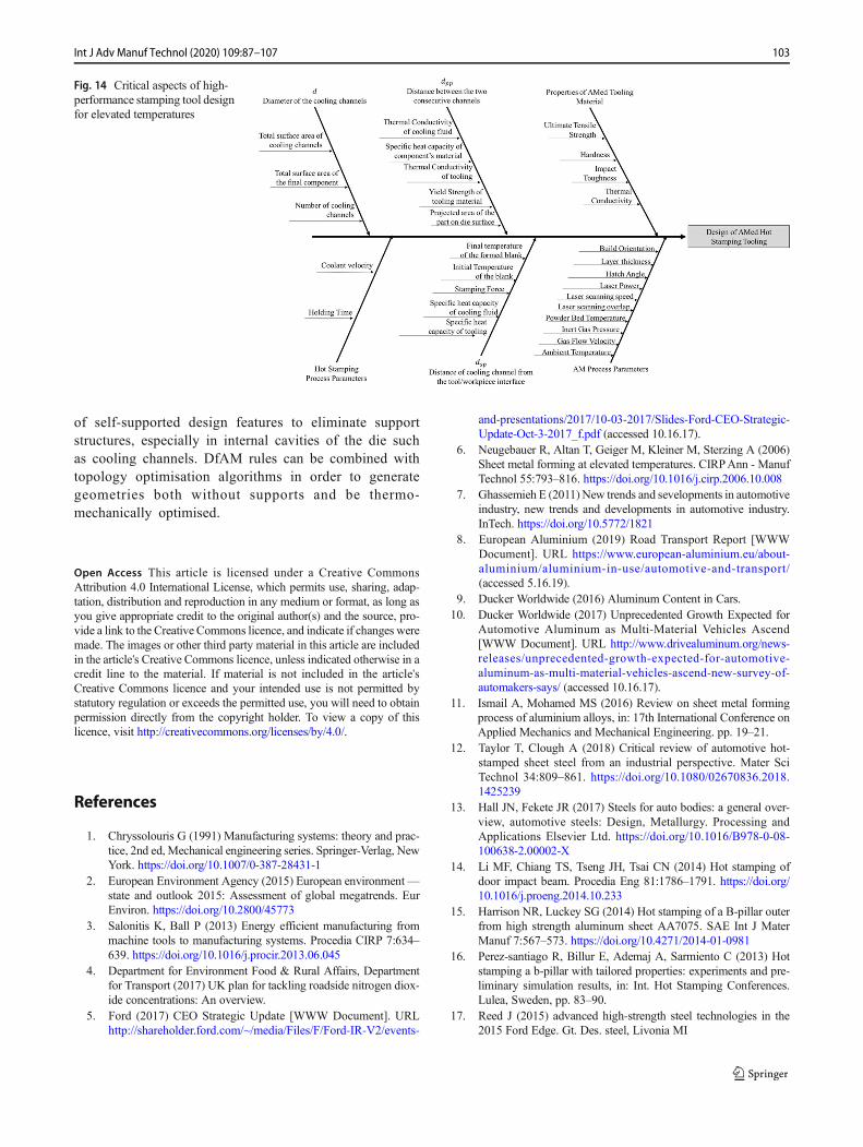
structural integrity or thermal performance. Moreover, themanufacture of bespoke cellular geometries such as latticestructures can selectively substitute solid areas within the die’sbody and enhance its thermal performance. In summary, thekey aspects which a designer must consider during the devel-opment of an AMed hot stamping die are presented in Fig. 14.However, there are significant gaps in the research whichmustbe addressed to enable the successful adoption of AM in thehot stamping tooling industry. These efforts should focus onthree main areas.
The first area is the characterisation of AMed materialswhich are suitable for hot stamping die manufacture.Conventionally manufactured and widely established hot toolsteels demonstrate properties of at least 1300 MPa tensilestrength, 50 HRC hardness, 18 J of impact toughness and 22W/mK of thermal conductivity. Any AMed materials shoulddemonstrate at least these properties in order to be considereda reliable alternative.
AM refers to a family of processes such as DED andPBF processes or even binder jetting. The authors recom-mend that PBF processes and specifically SLM be a suit-able process for hot stamping die manufacture, because it
Table 4 Overview of commercially available SLM materials
Powder material Supplier Tensile strength Hardness Impact toughness Thermal conductivity Reference
AlSi10Mg EOS 460 MPa 120HBW - 120 W/mK [114]
AlSi10Mg SLM Solutions 428 MPa 122 HV - - [115]
AlSi10Mg Renishaw 366 MPa 113 HV - 190 W/mK [116]
Cobalt fhrome MP1 EOS 1350 MPa 45 HRC - 13 W/mK [117]
H13 SLM Solutions 1888 MPa - - - [115]
Steel CL50WS Concept Laser 1969 MPa 52HRC - 20 W/mK [118]
Maraging steel Renishaw 1952 MPa 561 HV - 14.2WmK [119]
Maraging steel 1.2709 SLM Solutions 1784 MPa 373 HV[10] - - [115]
Maraging steel MS1 EOS 1930 MPa 56HRC 15 J 20 W/mK [120]
Nickel alloy CL100NB Concept Laser 1047 MPa - - 12 W/mK [121]
Nickel alloy HX EOS 820 MPa - - - [122]
Nickel alloy HX SLM Solutions 800 MPa 248 HV - - [115]
Nickel alloy IN625 EOS 827 MPa 30HRC - - [123]
Nickel alloy IN625 SLM Solutions 961 MPa 285 HV - - [115]
Nickel alloy IN625 Renishaw 1055 MPa 332 HV - 10.7 W/mK [124]
Nickel alloy IN718 EOS 1241 MPa 47HRC - - [125]
Nickel alloy IN718 SLM Solutions 1034 MPa 293 HV - - [115]
Nickel alloy IN718 Renishaw 1379 MPa 456 HV 12 W/mK [126]
Stainless steel 316 L SLM Solutions 633 MPa 209 HV - - [115]
Stainless steel 316 L Renishaw 624 MPa 208 HV - 16.2 W/mK [127]
Stainless steel CL20ES Concept Laser 640 MPa 20HRC - 15 W/mK [128]
Stainless steel CX EOS 1760 MPa 51HRC - - [129]
Titanium alloy Ti6Al4V SLM Solutions 1301 MPa 380 HV - - [115]
Titanium alloy Ti6Al4V Renishaw 1085 MPa 372 HV - 8 W/mK [130]
Titanium alloy CLTI41 Concept Laser 1106 MPa - - 7 W/mK [131]
99Int J Adv Manuf Technol (2020) 109:87–107

Table5
Summaryof
keyprocessparametersin
SLM/SLS[134]
Laser
andscanning
parameters
Powderproperties
(materialp
roperties)
Pow
derbedandrecoatparameters
Build
environm
entp
aram
eters
Param
eter
Type
Param
eter
Type
Parameter
Type
Parameter
Type
Average
power
Controlled
Bulkdensity
Predefin
edDensity
Predefin
edShieldgas
Predefin
ed
Laser
mode
Predefin
edTherm
alconductiv
ityPredefin
edTherm
alconductiv
ityPredefin
edOxygenlevel
Predefin
ed
Peak
power
Predefin
edHeatcapacity
Predefin
edHeatcapacity
Predefin
edSh
ield
gasmolecular
weight
Predefin
ed
Pulse
width
Predefin
edLatenth
eato
ffusion
Predefin
edAbsorptivity
Predefin
edShieldgasviscosity
Predefin
ed
Frequency
Predefin
edMeltin
gtemperature
Predefin
edEmissivity
Predefin
edTherm
alconductiv
ityPredefin
ed
Wavelength
Predefin
edMeltp
oolv
iscosity
Predefin
edDeposition
system
Predefin
edHeatcapacity
ofGas
Predefin
ed
Polarization
Predefin
edTherm
alexpansioncoefficient
Predefin
edRe-coater
type
Predefin
edPressure
Controlled
Beam
quality
Predefin
edSurface
free
energy
Predefin
edLayer
thickness
Controlled
Gas
glow
velocity
Controlled
Intensity
profile
Predefin
edVapor
pressure
Predefin
edPow
derbedtemperature
Controlled
Convectiveheattransfer
coefficient
Predefin
ed
Scanspeed
Controlled
Enthalpy
Predefin
edAmbienttem
perature
Controlled
Spotsize
Controlled
Absorptivity
Predefin
edSurface-freeenergy
Predefin
ed
Hatching
Controlled
Diffusivity
Predefin
edScanning
strategy
Controlled
Solubility
Predefin
ed
Particlemorphology
Predefin
ed
Surfaceroughness
Predefin
ed
Particlesize
distributio
nPredefin
ed
Contamination
Predefin
ed
100 Int J Adv Manuf Technol (2020) 109:87–107

is a fastest growing AM process in the industry, leading tosignificant know-how already in place in the supplychain, combined with continuously developed powdermaterials. Moreover, SLM demonstrates greater dimen-sional accuracy and surface roughness than DED or otherPBF processes as well as the ability to manufacture com-plex geometries such as lattice structures and conformalcooling channels. Both industrial suppliers and researchinstitutes have conducted material characterisation studiesto a variety of SLMed materials, ranging from AlSi10Mgto Ti6Al4V. Grades of maraging steel or H13 can be con-sidered a potential alternative to conventional tooling ma-terials as they meet most of the defined thresholds, al-though significant research efforts are required to studythe thermal conductivity of these grades. Moreover, AMis a delicate process with a high-level of anisotropy, andthe quality of the final component can be affected by over50 process parameters. In addition, conclusions can bedrawn from the currently available literature. LaserVolumetric Energy Density (VED) between 60 J/mm3
and 100 J/mm3 is required to deliver a fully dense micro-structure. Since VED is a function of laser power, scan-ning speed, layer thickness and laser overlap, the afore-mentioned range of VED can be achieved by a combina-tion of these parameters. For all the investigated studies,the hatch angle was set at 67 degrees. Moreover, it ishighlighted that heat treatment after printing significantlyincreases the hardness of the final component. The
optimal heat treatment strategy for maraging steel is aheating cycle of 6 hours at 480oC. Additionally, in thecase of H13, it was found that parts printed with a powderbed temperature of 400oC demonstrate a homogeneousmicrostructure and improved mechanical properties com-pared with parts produced with or without lower powderbed temperature. Thus far, published data has demonstrat-ed the potential for H13 and maraging steel, althoughfurther investigations are required to understand the effectof each process parameter on the quality of a functionalAMed die. For instance, there are insufficient availabledata on temperature-dependent material properties. Thisaspect must be further investigated since the operatingtemperature of hot stamping significantly affects the per-formance of an AM die.
The second area of study is the development of simula-tion models for the internal cooling system of hot stampingdies. It is shown that cooling systems with conformal chan-nels eliminate hot spots on the dies, providing uniformproperties on the final components, as well as increasedquenching efficiency and consequently decreased processcycle time. Manufacturing of conformal cooling channelsis limited by conventional manufacturing processes due tocost implications, although AM technologies can producethese types of channels without any additional cost. Theexisting models, which drive the design of the coolingsystems, address areas related to the diameter of a coolingchannel, its distance from the die working surface and the
Table 6 Key studies on process development of SLM
Authors Scope Material Key remarks
([139,140],
[141]
Laser average power and scanningspeed
Ti6Al4V,Mg-9%Al, SS
316 L
Process maps between laser speed and power indicates the available processwindow for each powder.
[142] Laser scanning hatch angle SS 304 Changing hatch angle and an increasing interval number (N) also aids in limitinggrain growth in a single direction, minimizing anisotropy in mechanicalproperties and residual stress, as well as increasing tensile strength
[143],[144][145]
Effect of powder deposition systemon part quality
Regardless Powder deposition system guarantees uniform layer thickness which leads to ahomogeneous material solidification
Increased blade velocities lead to dynamic powder post-flow and decreased meanlayer thicknesses
Increase of recoating time influences thermal gradient along the building axis. Ahigher recoating time allows more time for the part to cool down between layers
[146] Layer thickness impact on materialproperties
SS 316 L Layer thickness has a significant effect on microhardness. A thicker layer reduceshardness and tensile strength
[147] Powder bed temperature effect onmaterial properties and quality
SS 316 L Increase of powder bed temperature increases part density and improvesdimensional accuracy
([148,149],
[150]
Gas flow, Velocity and pressure Al-12Si,SS 316 L
For Al-12Si powder, the type of gas used did not significantly affect the part densityor hardness, with a maximum density of 98%
316 L SS samples fabricated under Ar, N2 and their mixtures with H2 exhibit nearfull density with values above 99%
Maximummelt pool temperature should not exceed the vaporization temperature ofthe powder and vaporization temperature changes with the gas pressure in thebuilding chamber
101Int J Adv Manuf Technol (2020) 109:87–107

distance between two consecutive cooling channels.However, most of the proposed models must be adjustedunder the prism of AM. In the case of analytical models,thermal conductivity and tensile strength of the die mate-rial should be adjusted to the “AM equivalent” propertiesas their values are heavily dependent on the manufacturingstrategy. Moreover, the cross section of AMed coolingchannels in mostly not circular. As a result, the volumeof the cooling medium flowing through the channel canbe affected leading to different cooling results. On the oth-er hand, the main challenge in computational models, apartfrom the development of material cards for AM materials,
is the discretisation of highly complex geometries that canbe generated by applying a Design for AM (DfAM) ap-proach. Lattice structures are design features that can behighly utilised in the design of a hot stamping dies, buttheir relatively small dimensions compared with the wholedie can increase the computational cost during a FEA.Segmented models and homogenisation techniques canhelp to direct efficient simulation models.
Finally, the third area of proposed work refers to thedevelopment of Design for Additive Manufacturing(DfAM) rules for hot stamping tooling applications.One of the most critical issues in this area is the design
Table 7 Key studies on process development of SLMed materials suitable for hot stamping applications
Authors Scope Material Key Remarks
[151] Microstructure and mechanical propertiescharacterisation
Maragingsteel
18Ni-300
Maximum hardness 58HRCMaximum UTS 2216 MPaCharpy impact 5 J with heat treatment
[152] Microstructure and mechanical propertiescharacterisation
H13 Ferritic/martensitic steels can be robustly processed by SLM by inducingretained austenite within the microstructures improving the mechanicalproperties of such steels without the necessity of employing a subsequentheat treatment
[153] Experimental investigation on processwindows of maraging steel 18Ni300
Maragingsteel
18Ni300
Laser power higher than 90 Wand laser scanning speed lower than 220 mm/scan deliver parts with densities greater than 99%. Reported ultimate tensilestrength (UTS) and hardness values are 1085–1192 MPa and 30–35 HRC,respectively. In this study, the specimens were not heat treated
[154] Effect of preheating on the SLM of H13 H13 Preheating temperatures of 400oC during SLM deliver parts with bettermechanical properties than parts produced without or with lower preheating(200 oC). SLMed H13 UTS (1965 MPa) is similar to conventionallyproduced H13 and the hardness is significantly higher (667HV0.5)
[155] Hardness investigation H13 Tempered directly after SLM, H13 specimens exhibit similar hardness levelwith conventional heat treated bulk H13 material. However, the peak insecondary hardness of SLM H13 specimens is shifted to highertemperatures and this phenomenon should be further investigated
[156] Applicability investigation of MS18Ni300 Maragingsteel
18Ni300
Heat treatment is necessary for SLM of MS18Ni300 in order to achieveoptimum harndess (650 HV) and UTS (2100 MPa)
[157] Experimental investigation on processwindows of MS300 including anisotropyeffect
Maragingsteel 300
Heat treatments were crucial to improve the properties of SLM-produced MSand eliminating mechanical anisotropy. Density wise, the optimum laserenergy density is found at 67 J/mm3. The highest UTS, HRC and charpyimpact energy values were 2014 MPa, 54.6 HRC and 15.5 J, respectively.
[158] Experimental investigation on processwindows of H13
H13 Fully dense parts can be achieved with and without preheating with aminimum energy density of 60 J/mm3. Achieved hardness by SLM iscomparable to a conventionally produced H13 tool steel
[159] Fatigue characterisation of SLMed MS1 Maragingsteel MS1
Fatigue life of SLMedMS1 is identified at 581MPa, corresponding to 28% ofthe UTS
(Wanget al.,2019)
High temperature properties of SLMed H13 H13 Effects of tempering temperature and holding time of the softening resistancetreatment were systematicaly studied. SLMed H13 exhibits higher hardnessthan wrought counterparts (650 HV compared to 600 HV). Moreover,SLMed specimens showed a hardness of 475 HV when tempering for 12hours at 600 C, which was closed to the wrought parts after 4 hourstreatment (496 HV)
[160] Process parameters effect of MS300 onresidual stresses and porosity
MS300 Strong relationship between process parameters and porosity, residual stressesand associated distortions. Increasing layer thickness results in a decline inresidual stresses and distortion (less than 0.6 mm) but can increase porosityby up to 5%
102 Int J Adv Manuf Technol (2020) 109:87–107
of self-supported design features to eliminate supportstructures, especially in internal cavities of the die suchas cooling channels. DfAM rules can be combined withtopology optimisation algorithms in order to generategeometries both without supports and be thermo-mechanically optimised.
Open Access This article is licensed under a Creative CommonsAttribution 4.0 International License, which permits use, sharing, adap-tation, distribution and reproduction in any medium or format, as long asyou give appropriate credit to the original author(s) and the source, pro-vide a link to the Creative Commons licence, and indicate if changes weremade. The images or other third party material in this article are includedin the article's Creative Commons licence, unless indicated otherwise in acredit line to the material. If material is not included in the article'sCreative Commons licence and your intended use is not permitted bystatutory regulation or exceeds the permitted use, you will need to obtainpermission directly from the copyright holder. To view a copy of thislicence, visit http://creativecommons.org/licenses/by/4.0/.
References
1. Chryssolouris G (1991) Manufacturing systems: theory and prac-tice, 2nd ed, Mechanical engineering series. Springer-Verlag, NewYork. https://doi.org/10.1007/0-387-28431-1
2. European Environment Agency (2015) European environment—state and outlook 2015: Assessment of global megatrends. EurEnviron. https://doi.org/10.2800/45773
3. Salonitis K, Ball P (2013) Energy efficient manufacturing frommachine tools to manufacturing systems. Procedia CIRP 7:634–639. https://doi.org/10.1016/j.procir.2013.06.045
4. Department for Environment Food & Rural Affairs, Departmentfor Transport (2017) UK plan for tackling roadside nitrogen diox-ide concentrations: An overview.
5. Ford (2017) CEO Strategic Update [WWW Document]. URLhttp://shareholder.ford.com/~/media/Files/F/Ford-IR-V2/events-
and-presentations/2017/10-03-2017/Slides-Ford-CEO-Strategic-Update-Oct-3-2017_f.pdf (accessed 10.16.17).
6. Neugebauer R, Altan T, Geiger M, Kleiner M, Sterzing A (2006)Sheet metal forming at elevated temperatures. CIRPAnn - ManufTechnol 55:793–816. https://doi.org/10.1016/j.cirp.2006.10.008
7. Ghassemieh E (2011)New trends and sevelopments in automotiveindustry, new trends and developments in automotive industry.InTech. https://doi.org/10.5772/1821
8. European Aluminium (2019) Road Transport Report [WWWDocument]. URL https://www.european-aluminium.eu/about-aluminium/aluminium-in-use/automotive-and-transport/(accessed 5.16.19).
9. Ducker Worldwide (2016) Aluminum Content in Cars.10. Ducker Worldwide (2017) Unprecedented Growth Expected for
Automotive Aluminum as Multi-Material Vehicles Ascend[WWW Document]. URL http://www.drivealuminum.org/news-releases/unprecedented-growth-expected-for-automotive-aluminum-as-multi-material-vehicles-ascend-new-survey-of-automakers-says/ (accessed 10.16.17).
11. Ismail A, Mohamed MS (2016) Review on sheet metal formingprocess of aluminium alloys, in: 17th International Conference onApplied Mechanics and Mechanical Engineering. pp. 19–21.
12. Taylor T, Clough A (2018) Critical review of automotive hot-stamped sheet steel from an industrial perspective. Mater SciTechnol 34:809–861. https://doi.org/10.1080/02670836.2018.1425239
13. Hall JN, Fekete JR (2017) Steels for auto bodies: a general over-view, automotive steels: Design, Metallurgy. Processing andApplications Elsevier Ltd. https://doi.org/10.1016/B978-0-08-100638-2.00002-X
14. Li MF, Chiang TS, Tseng JH, Tsai CN (2014) Hot stamping ofdoor impact beam. Procedia Eng 81:1786–1791. https://doi.org/10.1016/j.proeng.2014.10.233
15. Harrison NR, Luckey SG (2014) Hot stamping of a B-pillar outerfrom high strength aluminum sheet AA7075. SAE Int J MaterManuf 7:567–573. https://doi.org/10.4271/2014-01-0981
16. Perez-santiago R, Billur E, Ademaj A, Sarmiento C (2013) Hotstamping a b-pillar with tailored properties: experiments and pre-liminary simulation results, in: Int. Hot Stamping Conferences.Lulea, Sweden, pp. 83–90.
17. Reed J (2015) advanced high-strength steel technologies in the2015 Ford Edge. Gt. Des. steel, Livonia MI
Fig. 14 Critical aspects of high-performance stamping tool designfor elevated temperatures
103Int J Adv Manuf Technol (2020) 109:87–107

18. Bruschi, S., Ghiotti, A., 2018. Advanced forming technologieslearn more about hot stamping process hot stamping process.
19. Lin T, Song HW, Zhang SH, Cheng M, Liu WJ (2014) Coolingsystems design in hot stamping tools by a thermal-fluid-mechanical coupled approach. Adv Mech Eng 2014:545727.https://doi.org/10.1155/2014/545727
20. Xavier LF, Elangovan D (2013) Effective parameters for improv-ing deep hole drilling process by conventional method - a review.Int J Eng Res Technol:2
21. Mellor S, Hao L, Zhang D (2014) Additive manufacturing: aframework for implementation. Int J Prod Econ 149:194–201.https://doi.org/10.1016/j.ijpe.2013.07.008
22. Ngo TD, Kashani A, Imbalzano G, Nguyen KTQ, Hui D (2018)Additive manufacturing (3D printing): A review of materials,methods, applications and challenges. Compos Part B Eng 143:172–196. https://doi.org/10.1016/j.compositesb.2018.02.012
23. Armillotta A, Baraggi R, Fasoli S (2014) SLM tooling for diecasting with conformal cooling channels. Int J Adv ManufTechnol 71:573–583. https://doi.org/10.1007/s00170-013-5523-7
24. Au KM, Yu KM (2007) A scaffolding architecture for conformalcooling design in rapid plastic injection moulding. Int J AdvManuf Technol 34:496–515. https://doi.org/10.1007/s00170-006-0628-x
25. Ferreira JC, Mateus A (2003) Studies of rapid soft tooling withconformal cooling channels for plastic injectionmoulding. JMaterProcess Technol 142:508–516. https://doi.org/10.1016/S0924-0136(03)00650-2
26. Jahan SA, El-Mounayri H (2016) Optimal conformal coolingchannels in 3D printed dies for plastic injection molding.Procedia Manuf 5:888–900. https://doi.org/10.1016/j.promfg.2016.08.076
27. Park HS, Dang XP (2010) Optimization of conformal coolingchannels with array of baffles for plastic injection mold. Int JPrecis Eng Manuf 11:879–890. https://doi.org/10.1007/s12541-010-0107-z
28. Xu X, Sachs E, Allen S (2001) The design of conformal coolingchannels in injection molding tooling. Polym Eng Sci 41:1265–1279. https://doi.org/10.1002/pen.10827
29. Karbasian H, Tekkaya AE (2010) A review on hot stamping. JMater Process Technol 210:2103–2118. https://doi.org/10.1016/j.jmatprotec.2010.07.019
30. Merklein M, Lechler J, Stoehr T (2008) Characterization of tribo-logical and thermal properties of metallic coatings for hotstamping boron-manganese steels. Manuf Eng 1–3
31. Lechler J, Merklein M (2008) Hot stamping of ultra high strengthsteels as a key technology for lightweight construction, in:Materials Science and Technology. Pittsburgh, Pennsylvania
32. Naderi M (2007) Hot stamping of ultra high strength steels 190.28187
33. Abdollahpoor A, Chen X, Pereira MP, Xiao N, Rolfe BF (2016)Sensitivity of the final properties of tailored hot stamping compo-nents to the process and material parameters. J. Mater. Process.Technol. 228:125–136. https://doi.org/10.1016/j.jmatprotec.2014.11.033
34. Merklein M, Wieland M, Lechner M, Bruschi S, Ghiotti A (2016)Hot stamping of boron steel sheets with tailored properties: Areview. J Mater Process Technol 228:11–24. https://doi.org/10.1016/j.jmatprotec.2015.09.023
35. Mu Y, Wang B, Zhou J, Huang XU, Li X (2017) Hot stamping ofboron steel using partition heating for tailored properties: experi-mental trials and numerical analysis. Metall Mater Trans A 48:5467–5479. https://doi.org/10.1007/s11661-017-4270-z
36. Venturato G, Novella M, Bruschi S, Ghiotti A, Shivpuri R (2017)Effects of phase transformation in hot stamping of 22MnB5 highstrength steel. Procedia Eng 183:316–321. https://doi.org/10.1016/j.proeng.2017.04.045
37. Muller B, Gebauer M, Hund R, Malek R, Gerth N (2014) Metaladditive manufacturing for tooling applications - laser beam melt-ing technology increases efficiency of dies and molds. In: MetalAdditive Manufacturing Conference (MAM). Wien, pp 1–14
38. Gao H, El Fakir O, Wang L, Politis DJ, Li Z (2017) Forming limitprediction for hot stamping processes featuring non-isothermaland complex loading conditions. Int J Mech Sci 131–132:792–810. https://doi.org/10.1016/j.ijmecsci.2017.07.043
39. Wang A, Zhong K, El Fakir O, Liu J, Sun C, Wang LL, Lin J,Dean TA (2017) Springback analysis of AA5754 after hotstamping: experiments and FE modelling. Int J Adv ManufTechnol 89:1339–1352. https://doi.org/10.1007/s00170-016-9166-3
40. El Fakir O, Wang L, Balint D, Dear JP, Lin J, Dean TA (2014)Numerical study of the solution heat treatment, forming, and in-die quenching (HFQ) process on AA5754. Int J Mach ToolsManuf 87:39–48. https://doi.org/10.1016/j.ijmachtools.2014.07.008
41. Garrett RP, Lin J, Dean TA (2005) An investigation of the effectsof solution heat treatment on mechanical properties for AA 6xxxalloys: Experimentation and modelling. Int J Plast 21:1640–1657.https://doi.org/10.1016/j.ijplas.2004.11.002
42. Wang L, Strangwood M, Balint D, Lin J, Dean TA (2011)Formability and failure mechanisms of AA2024 under hotforming conditions. Mater Sci Eng A 528:2648–2656. https://doi.org/10.1016/j.msea.2010.11.084
43. Foster AD, Dean TA, Lin J (2010) Process for forming aluminiumalloy sheet component. International Patent No.: WO2010/032002 A1.
44. Lin, J., Balint, D., Wang, L., Dean, T.A., Foster, A.D., 2011. Amethod of forming a component of complex shape from sheetmaterial. UK Patent No.: GB2473298.
45. Impression Technologies Ltd (2013) HFQ technology [WWWDocument].
46. Wang, L., Fakir, O. El, Sun, Y., Ji, K., Luan, X., Cai, Z., Liu, X.,2019a. A method of forming parts from sheet metal. InternationalPatent No.: WO2019/038556.
47. Wang M, Li W, Wu Y, Li S, Cai C, Wen S, Wei Q, Shi Y, Ye F,Chen Z (2019b) High-temperature properties and microstructuralstability of the AISI H13 hot-work tool steel processed by selec-tive laser melting. Metall Mater Trans B Process Metall MaterProcess Sci 50:531–542. https://doi.org/10.1007/s11663-018-1442-1
48. Luan X, Zhang QL, Fakir OE,Wang LL, Gharbi MM (2017) Uni-Form: a pilot production line for hot/warm sheet metal formingintegrated in a Cloud Based SMARTFORMING platform. In: The3rd International Conference on Advanced High Strength Steeland Press Hardening, pp 492–497. https://doi.org/10.1142/9789813207301_0067
49. Smart Forming (2019) Smart forming technology platform[WWW Document].
50. Zhang Q, Luan X, Dhawan S, Politis DJ, Du Q, FuMW,Wang K,Gharbi MM, Wang L (2019) Development of the post-formstrength prediction model for a high-strength 6xxx aluminiumalloy with pre-existing precipitates and residual dislocations. IntJ Plast 119:230–248. https://doi.org/10.1016/j.ijplas.2019.03.013
51. Harrison NR, Luckey SG (2014) Hot Stamping of a B-Pillar Outerfrom High Strength Aluminum Sheet AA7075. SAE Int J MaterManuf 7:2014–01–0981. https://doi.org/10.4271/2014-01-0981
52. Zhou J, Wang B, Lin J, Fu L (2013) Optimization of an aluminumalloy anti-collision side beam hot stamping process using a multi-objective genetic algorithm. Arch Civ Mech Eng 13:401–411.https://doi.org/10.1016/j.acme.2013.01.008
53. Liu X, Ji K, El Fakir O, Fang H, Gharbi MM, Wang LL (2017a)Determination of the interfacial heat transfer coefficient for a hot
104 Int J Adv Manuf Technol (2020) 109:87–107

aluminium stamping process. J Mater Process Technol 247:158–170. https://doi.org/10.1016/j.jmatprotec.2017.04.005
54. Liu Y, Zhu Z, Wang Z, Zhu B, Wang Y, Zhang Y (2017b)Formability and lubrication of a B-pillar in hot stamping with6061 and 7075 aluminum alloy sheets. Procedia Eng 207:723–728. https://doi.org/10.1016/j.proeng.2017.10.819
55. Song Y, Dai D, Geng P, Hua L (2017) Formability of aluminumalloy thin-walled cylinder parts by servo hot stamping. ProcediaEng 207:741–746. https://doi.org/10.1016/j.proeng.2017.10.822
56. Maeno T, Mori K, Yachi R (2017) CIRPAnnals - Manufacturingtechnology hot stamping of high-strength aluminium alloy aircraftparts using quick heating. CIRP Ann - Manuf Technol 66:269–272. https://doi.org/10.1016/j.cirp.2017.04.117
57. Milkereit B, ÖsterreichM, Schuster P, Kirov G (2018) Dissolutionand precipitation behavior for hot forming of 7021 and 7075 alu-minum alloys. Metals (Basel) 8. https://doi.org/10.3390/met8070531
58. Milkereit B,Wanderka N, Schick C, Kessler O (2012) Continuouscooling precipitation diagrams of Al-Mg-Si alloys. Mater Sci EngA 550:87–96. https://doi.org/10.1016/j.msea.2012.04.033
59. Yun S, Kwon J, Cho W, Lee DC, Kim Y (2020) Performanceimprovement of hot stamping die for patchwork blank usingmixed cooling channel designs with straight and conformal chan-nels. Appl Therm Eng 165:114562. https://doi.org/10.1016/j.applthermaleng.2019.114562
60. Escher C, Wilzer JJ (2015) Tool steels for hot stamping of highstrength automotive body parts. Int Conf Stone Concr Mach 3:219–228
61. Tang D, Eversheim W, Schuh G (2004) Qualitative and quantita-tive cost analysis for sheet metal stamping. Int J Comput IntegrM a n u f 1 7 : 3 9 4 – 4 1 2 . h t t p s : / / d o i . o r g / 1 0 . 1 0 8 0 /09511920410001662120
62. Axinte D, Dewes R (2010) High-speed milling of AISI H13 hot-work tool steel using polycrystalline cubic boron nitride ball-nosemills: From experimental investigations and empirical modellingto functional testing of the machined surfaces. Proc Inst Mech EngPart B J Eng Manuf 224:15–24. https://doi.org/10.1243/09544054JEM1630
63. Gunnarsson S, Nordh LG (2002) The influence of steel grade andsteel hardness on tool life when milling in hardened tool steel, in:Proceedings of the 6th International Tooling Conference - TheUseof Tool Steels - Experience and Research. Karlstad, pp. 1199–1208.
64. Sandberg N (2017) on the machinability of high performance toolsteels. Uppsala Universitet
65. Donghao LIU (2018) Die manufacturing process the best flowfrom idea to delivery tutor. Politecnico di Torino
66. Cortina M, Arrizubieta J, Calleja A, Ukar E, Alberdi A (2018)Case study to illustrate the potential of conformal cooling channelsfor hot stamping dies manufactured using hybrid process of lasermetal deposition (LMD) and milling. Metals (Basel) 8:102.https://doi.org/10.3390/met8020102
67. Valls I, Casas B, Rodríguez N, Paar U (2010) Benefits from usinghigh thermal conductivity tool steels in the hot forming of steels.Metall Ital 102:23–28
68. Lim WS, Choi HS, Ahn SY, Kim BM (2014) Cooling channeldesign of hot stamping tools for uniform high-strength compo-nents in hot stamping process. Int J Adv Manuf Technol 70:1189–1203. https://doi.org/10.1007/s00170-013-5331-0
69. Mazur M, Leary M, McMillan M, Elambasseril J, Brandt M(2016) SLM additive manufacture of H13 tool steel with confor-mal cooling and structural lattices. Rapid Prototyp J 22:504–518.https://doi.org/10.1108/RPJ-06-2014-0075
70. Au KM, Yu KM (2011) Modeling of multi-connected porous pas-sageway for mould cooling. CAD Comput Aided Des 43:989–1000. https://doi.org/10.1016/j.cad.2011.02.007
71. Brooks H, Brigden K (2016) Design of conformal cooling layerswith self-supporting lattices for additively manufactured tooling.Addit Manuf 11:16–22. https://doi.org/10.1016/j.addma.2016.03.004
72. Canellidis V, Giannatsis J, Dedoussis V (2009)Genetic-algorithm-based multi-objective optimization of the build orientation instereolithography. Int J Adv Manuf Technol 45:714–730. https://doi.org/10.1007/s00170-009-2006-y
73. Hur J, Lee K (1998) The development of a CAD environment todetermine the preferred build-up direction for layered manufactur-ing. Int J Adv Manuf Technol 14:247–254. https://doi.org/10.1007/BF01199879
74. Hartunian P, Eshraghi M (2018) Effect of build orientation on themicrostructure and mechanical properties of selective laser-meltedTi-6Al-4 VAlloy. J Manuf Mater Process 2:69. https://doi.org/10.3390/jmmp2040069
75. Simonelli M, Tse YY, Tuck C (2014) Effect of the build orienta-tion on the mechanical properties and fracture modes of SLM Ti-6Al-4 V. Mater Sci Eng A 616:1–11. https://doi.org/10.1016/j.msea.2014.07.086
76. Das P, Chandran R, Samant R, Anand S (2015) Optimum partbuild orientation in additive manufacturing for minimizing parterrors and support structures. Procedia Manuf 1:343–354.https://doi.org/10.1016/j.promfg.2015.09.041
77. Langelaar M (2018) Combined optimization of part topology,support structure layout and build orientation for additivemanufacturing. Struct Multidiscip Optim 57:1985–2004. https://doi.org/10.1007/s00158-017-1877-z
78. McClurkin JE, Rosen DW (1998) Computer-aided build style de-cision support for stereolithography. Rapid Prototyp J 4:4–13.https://doi.org/10.1108/13552549810197505
79. Charkaluk E, Chastand V (2018) Fatigue of additive manufactur-ing specimens: a comparison with casting processes. Proceedings2:474. https://doi.org/10.3390/icem18-05352
80. Jiang C, Shan Z, Zhuang B, ZhangM, Xu Y (2012) Hot stampingdie design for vehicle door beams using ultra-high strength steel.Int J Precis Eng Manuf 13:1101–1106. https://doi.org/10.1007/s12541-012-0144-x
81. Shan Z-d,Mi-lan Z, Chao J, XuY,Wen-juan R (2010) Basic studyon die cooling system of hot stamping process, in: InternationalConference on Advanced Technology of Design and Manufacture(ATDM 2010). IET, Beijing, pp 1–4. https://doi.org/10.1049/cp.2010.1248
82. Rao N, Schumacher G, Schott N, O’Brien K (2002) optimizationof cooling systems in injection molds by an easily applicable an-alytical model. J Reinf Plast Compos 21:451–459. https://doi.org/10.1106/073168402026471
83. Lei C, Cui J, Xing Z, Fu H, Zhao H (2012) Investigation ofcooling effect of hot-stamping dies by numerical simulation.Phys Procedia 25:118–124. https://doi.org/10.1016/j.phpro.2012.03.059
84. Ying X, Zhong-De S (2014) Design parameter investigation ofcooling systems for UHSS hot stamping dies. Int J Adv ManufTechnol 70:257–262. https://doi.org/10.1007/s00170-013-5272-7
85. De Shan Z, Ye YS, Zhang ML, Wang BY (2013) Hot-stampingdie-cooling system for vehicle door beams. Int J Precis EngManuf14:1251–1255. https://doi.org/10.1007/s12541-013-0170-3
86. Steinbeiss H, So H, Michelitsch T, Hoffmann H (2007) Methodfor optimizing the cooling design of hot stamping tools. Prod Eng1:149–155. https://doi.org/10.1007/s11740-007-0010-3
87. Chen J, Gong P, Liu Y, Zheng X, Ren F (2017) Optimization ofhot stamping cooling system using segmented model. Int J AdvManuf Technol 93:1357–1365. https://doi.org/10.1007/s00170-017-0504-x
88. Cheng X, Wei K, He R, Pei Y, Fang D (2016) The equivalentthermal conductivity of lattice core sandwich structure: A
105Int J Adv Manuf Technol (2020) 109:87–107

predictive model. Appl Therm Eng 93:236–243. https://doi.org/10.1016/j.applthermaleng.2015.10.002
89. Ptochos E, Labeas G (2012) Elastic modulus and Poisson’s ratiodetermination of micro-lattice cellular structures by analytical, nu-merical and homogenisation methods. J Sandw Struct Mater 14:597–626. https://doi.org/10.1177/1099636212444285
90. Gaynor AT, Guest JK (2016) Topology optimization consideringoverhang constraints: Eliminating sacrificial support material inadditive manufacturing through design. Struct Multidiscip Optim54:1157–1172. https://doi.org/10.1007/s00158-016-1551-x.
91. Li Z, Wang X, Gu J, Ruan S, Shen C, Lyu Y, Zhao Y (2018)Topology optimization for the design of conformal cooling systemin thin-wall injection molding based on BEM. Int J Adv ManufTechnol 94:1041–1059. https://doi.org/10.1007/s00170-017-0901-1
92. Leary M, Merli L, Torti F, Mazur M, Brandt M (2014) Optimaltopology for additive manufacture: a method for enabling additivemanufacture of support-free optimal structures. Mater Des 63:678–690. https://doi.org/10.1016/j.matdes.2014.06.015
93. Brackett D, Ashcroft I, Hague R (2011) Topology optimization foradditive manufacturing. 22nd Annu. Int. Solid Free. Fabr. Symp. -An Addit. Manuf. Conf. SFF 2011:348–362
94. Naganathan A, Penter L (2012) Hot Stamping, in: Altanm, T.,Tekkaya, E. (Eds.), sheet metal forming - processes and applica-tions. ASM Internation, pp 133–156
95. Hoffmann H, So H, Steinbeiss H (2007) Design of hot stampingtools with cooling system. CIRP Ann - Manuf Technol 56:269–272. https://doi.org/10.1016/j.cirp.2007.05.062
96. Zheng K, Lee J, Xiao W, Wang B, Lin J (2018) Experimentalinvestigations of the in-die quenching efficiency and die surfacetemperature of hot stamping aluminium alloys. Metals (Basel) 8:231. https://doi.org/10.3390/met8040231
97. Gumpel P, Bogatzky T, Huber A, Geigges B (2002) Comparisonof different characteristics of modern hot-work tool steels. 6th IntTool Conf:3–16
98. Benedyk JC (2008) High Performance Alloy Database- H13.99. Grellier A, Siaut M (2002) A new hot work tool steel for high
temperature and high stress service conditions. 6th Int. Tool. Conf.39–48.
100. Mueller, C., Schruff, I., 2016. Steel selection contributing to wearreduction of forging dies.
101. Rovalma (2009) Technical card HTCS-130WU.102. Qamar SZ (2015) Heat treatment and mechanical testing of AISI
H11 Steel. Key Eng Mater 656–657:434–439. https://doi.org/10.4028/www.scientific.net/KEM.656-657.434
103. Otai Steel (2019) 1.2367 Mechanical Properties [WWWDocument]. URL http://www.otaisteel.com/din-1-2367-hot-work-tool-steel/ (accessed 1.23.19).
104. Rovalma (2017) HTCS 130 Thermo-mechanical Properties[WWW Document]. URL http://rovalma.com/wp-content/uploads/2017/06/HTCS®-130WU.pdf (accessed 1.23.19).
105. Orsa Ltd (2016) HTCS-130 Thermo-mechanical Properties[WWW Document]. URL http://www.orsa-ltd.com/upload/files/katalog/Rovalma/ORSA-HTCS-130-sicak-is-toz-metal.pdf(accessed 1.23.19).
106. Schruff I (2012) The tool steel producer’s contribution to success-ful die casting of structural components. Metall Ital 104:37–43
107. Li S, Zhou L, Wu X, Zhang Y, Li J (2016) The influence ofthermal conductivity of die material on the efficiency of hot-stamping pProcess. J Mater Eng Perform 25:4848–4867. https://doi.org/10.1007/s11665-016-2332-9
108. Rahn, R., Schruff, I., 2015. The selection of tool steels for hot-stamping tools with respect to increased loads.
109. Ye YS, De Shan Z, Wang BY, Jiang C, Zhuang BL (2014) Amaterial selection criterion for hot-stamping dies. Appl Mech
Mater 490–491:25–28. https://doi.org/10.4028/www.scientific.net/AMM.490-491.25
110. ASTM International (2013) F2792-12a - Standard terminology foradditive manufacturing technologies. Rapid Manuf Assoc:10–12.https://doi.org/10.1520/F2792-12A.2
111. DebRoy T, Wei HL, Zuback JS, Mukherjee T, Elmer JW,Milewski JO, Beese AM, Wilson-Heid A, De A, Zhang W(2018) Additive manufacturing of metallic components –Process, structure and properties. Prog Mater Sci 92:112–224.https://doi.org/10.1016/j.pmatsci.2017.10.001
112. Renishaw (2017) Renishaw conformal cooling solutions prove aboost to moulding productivity.
113. Roland Berger (2019) Additive manufacturing - Taking metal 3Dprinting to the next level [WWW Document]. URL https://www.slideshare.net/MartinErharter/additive-manufacturing-taking-metal-3-d-printing-to-the-next-level-study-by-roland-berger-200943228 (accessed 5.10.20).
114. EOS GmbH (2019a) Material Datasheet - Aluminium AlSi10Mg[WWW Document]. URL https://www.eos.info/material-m(accessed 1.20.19).
115. SLM Solutions GmbH (2019) Material Data Sheet of AvailablePowders from SLM Solutions [WWW Document]. 10.2116/bunsekikagaku.53.1021
116. Renishaw (2019a) Material data sheet -AlSi10Mg [WWWDocument]. URL https://www.renishaw.com/en/data-sheets-additive-manufacturing%2D%2D17862 (accessed 1.20.19).
117. EOS GmbH (2019b) Material data sheet - Cobalt Chrome MP1[WWW Document]. URL https://www.eos.info/material-m(accessed 1.20.19).
118. Concept Laser GmbH (2019a) Material Datasheet CL 50WS[WWW Document]. URL https://www.concept-laser.de/en/products/materials.html (accessed 1.20.19).
119. Renishaw (2019b) Material data sheet - Maraging steel [WWWDocument]. URL https://www.renishaw.com/en/data-sheets-additive-manufacturing%2D%2D17862 (accessed 1.20.19).
120. EOS GmbH (2019c) Material Data Sheet - Maraging Steel MS1[WWW Document]. URL https://www.eos.info/material-m(accessed 1.20.19).
121. Concept Laser GmbH (2019b) Material Datasheet - CL 100NB[WWW Document]. URL https://www.concept-laser.de/en/products/materials.html (accessed 1.20.19).
122. EOS GmbH (2019d) Material Data Sheet - NickelAlloy HX[WWW Document]. URL https://www.eos.info/material-m(accessed 1.20.19).
123. EOS GmbH (2019e) Material data sheet - EOS Nickel AlloyIN625 [WWW Document]. URL https://www.eos.info/material-m (accessed 1.20.19).
124. Renishaw (2019c) Material data sheet - IN625 [WWWDocument]. URL https://www.renishaw.com/en/data-sheets-additive-manufacturing%2D%2D17862 (accessed 1.20.19).
125. EOS GmbH (2019f) Material Data Sheet IN718 [WWWDocument]. URL https://www.eos.info/material-m (accessed 1.20.19).
126. Renishaw (2019d) Material data sheet -Renishaw IN718 [WWWDocument]. URL https://www.renishaw.com/en/data-sheets-additive-manufacturing%2D%2D17862 (accessed 1.20.19).
127. Renishaw (2019e) Material data sheet - Stainless Steel 316 L[WWW Document]. URL https://www.renishaw.com/en/data-sheets-additive-manufacturing%2D%2D17862 (accessed 1.20.19).
128. Concept Laser GmbH (2019c)Material Datasheet - Stainless SteelCL 20ES [WWWDocument]. URL https://www.concept-laser.de/en/products/materials.html (accessed 1.20.19).
129. EOS GmbH (2019g) Material data sheet - Stainless Steel 316 L[WWW Document]. URL https://www.eos.info/material-m(accessed 1.20.19).
106 Int J Adv Manuf Technol (2020) 109:87–107

130. Renishaw (2019f) Material data sheet -Ti6Al4V [WWWDocument]. URL https://www.renishaw.com/en/data-sheets-additive-manufacturing%2D%2D17862 (accessed 1.20.19).
131. Concept Laser GmbH (2019d) Material Datasheet - CL Ti47[WWW Document]. URL https://www.concept-laser.de/en/products/materials.html (accessed 1.20.19).
132. Valls I, Hamasaiid A, Padré A (2018) New approaches to thermaltool performance, cooling and machining strategy: The stronglycorrelated triple that determines the cost effectiveness of the pro-cess. IOP Conf Ser Mater Sci Eng:418. https://doi.org/10.1088/1757-899X/418/1/012013
133. Gibson I, Rosen DW, Stucker B (2010) Additive manufacturingtechnologies. Springer US, Boston, MA. https://doi.org/10.1007/978-1-4419-1120-9
134. Spears TG, Gold SA (2016) In-process sensing in selective lasermelting (SLM) additive manufacturing. IntegrMaterManuf Innov5:16–40. https://doi.org/10.1186/s40192-016-0045-4
135. Gong H (2013) Generation and detection of defects in metallicparts fabricated by selective laser melting and electron beam melt-ing and their effects on mechanical properties. University ofLouisville. https://doi.org/10.18297/etd/515
136. Hitzler L, Hirsch J, Heine B,MerkelM, HallW, Öchsner A (2017)On the anisotropic mechanical properties of selective laser-meltedstainless steel. Materials (Basel):10. https://doi.org/10.3390/ma10101136
137. Deev AA, Kuznetcov PA, Petrov SN (2016) Anisotropy of me-chanical properties and its correlation with the structure of thestainless steel 316 L produced by the SLM method. PhysProcedia 83:789–796. https://doi.org/10.1016/j.phpro.2016.08.081
138. Kunze K, Etter T, Grässlin J, Shklover V (2014) Texture, anisot-ropy in microstructure and mechanical properties of IN738LCalloy processed by selective laser melting (SLM). Mater Sci EngA 620:213–222. https://doi.org/10.1016/j.msea.2014.10.003
139. Song B, Dong S, Zhang B, Liao H, Coddet C (2012) Effects ofprocessing parameters on microstructure and mechanical propertyof selective laser melted Ti6Al4V. Mater Des 35:120–125. https://doi.org/10.1016/j.matdes.2011.09.051
140. Zhang B, Liao H, Coddet C (2012a) Effects of processing param-eters on properties of selective laser melting Mg-9%Al powdermixture. Mater Des 34:753–758. https://doi.org/10.1016/j.matdes.2011.06.061
141. Gu D, Shen Y (2008) Processing conditions and microstructuralfeatures of porous 316 L stainless steel components by DMLS.Appl Surf Sci 255:1880–1887. https://doi.org/10.1016/j.apsusc.2008.06.118
142. Guan K, Wang Z, Gao M, Li X, Zeng X (2013) Effects of pro-cessing parameters on tensile properties of selective laser melted304 stainless steel. Mater Des Elsevier Ltd 50:581–586. https://doi.org/10.1016/j.matdes.2013.03.056
143. Hebert RJ (2016) Viewpoint: metallurgical aspects of powder bedmetal additive manufacturing. J Mater Sci 51:1165–1175. https://doi.org/10.1007/s10853-015-9479-x
144. Meier, C., Weissbach, R., Weinberg, J., Wall, W.A., Hart, A.J.,2018. Critical influences of particle size and adhesion on the pow-der layer uniformity in metal additive manufacturing.
145. Andreau O, Peyre P, Penot JD, Koutiri I, Dupuy C, Pessard E,Saintier N (2017) Deterministic defect generation in selective lasermelting: parametric optimization and control. Lasers Manuf -WLT eV:1–11
146. Ma M, Wang Z, Gao M, Zeng X (2015) Layer thickness depen-dence of performance in high-power selective laser melting of1Cr18Ni9Ti stainless steel. J Mater Process Technol 215:142–150. https://doi.org/10.1016/j.jmatprotec.2014.07.034
147. Zhang B, Zhu L, Liao H, Coddet C (2012b) Improvement ofsurface properties of SLM parts by atmospheric plasma sprayingcoating. Appl Surf Sci 263:777–782. https://doi.org/10.1016/j.apsusc.2012.09.170
148. Wang XJ, Zhang LC, Fang MH, Sercombe TB (2014) The effectof atmosphere on the structure and properties of a selective lasermelted Al-12Si alloy. Mater Sci Eng A 597:370–375. https://doi.org/10.1016/j.msea.2014.01.012
149. Zhang B, Dembinski L, Coddet C (2013) The study of the laserparameters and environment variables effect on mechanical prop-erties of high compact parts elaborated by selective laser melting316 L powder. Mater Sci Eng A 584:21–31. https://doi.org/10.1016/j.msea.2013.06.055
150. Masmoudi A, Bolot R, Coddet C (2015) Investigation of the laser-powder-atmosphere interaction zone during the selective lasermelting process. J Mater Process Technol 225:122–132. https://doi.org/10.1016/j.jmatprotec.2015.05.008
151. Kempen K, Yasa E, Thijs L, Kruth JP, Van Humbeeck J (2011)Microstructure and mechanical properties of selective laser melted18Ni-300 steel. Phys Procedia 12:255–263. https://doi.org/10.1016/j.phpro.2011.03.033
152. Holzweissig MJ, Taube A, Brenne F, Schaper M, Niendorf T(2015) Microstructural characterization and mechanical perfor-mance of hot work tool steel processed by selective laser melting.Metall Mater Trans B Process Metall Mater Process Sci 46:545–549. https://doi.org/10.1007/s11663-014-0267-9
153. Casalino G, Campanelli SL, Contuzzi N, Ludovico AD (2015)Experimental investigation and statistical optimisation of the se-lective laser melting process of a maraging steel. Opt LaserTechnol 65:151–158. https://doi.org/10.1016/j.optlastec.2014.07.021
154. Mertens R, Vrancken B, Holmstock N, Kinds Y, Kruth JP, VanHumbeeck J (2016) Influence of powder bed preheating on mi-crostructure and mechanical properties of H13 tool steel SLMparts. Phys Procedia 83:882–890. https://doi.org/10.1016/j.phpro.2016.08.092
155. Krell J, Röttger A, Geenen K, Theisen W (2018) General investi-gations on processing tool steel X40CrMoV5-1 with selectivelaser melting. J Mater Process Technol 255:679–688. https://doi.org/10.1016/j.jmatprotec.2018.01.012
156. Bai Y, Yang Y, Xiao Z, Wang D (2018) Selective laser melting ofmaraging steel: mechanical properties development and its appli-cation in mold. Rapid Prototyp J 24:623–629. https://doi.org/10.1108/RPJ-05-2017-0104
157. Tan C, ZhouK, KuangM,MaW, Kuang T (2018)Microstructuralcharacterization and properties of selective laser melted maragingsteel with different build directions. Sci Technol Adv Mater 19:746–758. https://doi.org/10.1080/14686996.2018.1527645
158. Narvan M, Al-Rubaie KS, Elbestawi M (2019) Process-structure-property relationships of AISI H13 tool steel processed with se-lective laser melting.Materials (Basel) 12:2284. https://doi.org/10.3390/ma12142284
159. Croccolo D, De Agostinis M, Fini S, Olmi G, Robusto F, Ćirić-Kostić S, Morača S, Bogojević N (2019) Sensitivity of directmetal laser sintering maraging steel fatigue strength to build ori-entation and allowance for machining. Fatigue Fract Eng MaterStruct 42:374–386. https://doi.org/10.1111/ffe.12917
160. Mugwagwa, Yadroitsev, Matope (2019) Effect of process param-eters on residual stresses, distortions, and porosity in selectivelaser melting of maraging steel 300. Metals (Basel) 9:1042.https://doi.org/10.3390/met9101042
Publisher’s note Springer Nature remains neutral with regard to jurisdic-tional claims in published maps and institutional affiliations.
107Int J Adv Manuf Technol (2020) 109:87–107