reviews on drag reducing polymers - cheric · molecular characteristics of different polymers on...
TRANSCRIPT

1455
Korean J. Chem. Eng., 32(8), 1455-1476 (2015)DOI: 10.1007/s11814-015-0104-0
REVIEW PAPER
pISSN: 0256-1115eISSN: 1975-7220
INVITED REVIEW PAPER
†To whom correspondence should be addressed.E-mail: [email protected], [email protected] by The Korean Institute of Chemical Engineers.
Reviews on drag reducing polymers
Angnes Ngieng Tze Tiong†, Perumal Kumar, and Agus Saptoro
Department of Chemical Engineering, Curtin University Sarawak Campus, CDT 250, 98009 Miri, Sarawak, Malaysia(Received 31 October 2014 • accepted 16 May 2015)
Abstract−Polymers are effective drag reducers owing to their ability to suppress the formation of turbulent eddies atlow concentrations. Existing drag reduction methods can be generally classified into additive and non-additive tech-niques. The polymer additive based method is categorized under additive techniques. Other drag reducing additivesare fibers and surfactants. Non-additive techniques are associated with the applications of different types of surfaces:riblets, dimples, oscillating walls, compliant surfaces and microbubbles. This review focuses on experimental and com-putational fluid dynamics (CFD) modeling studies on polymer-induced drag reduction in turbulent regimes. Otherdrag reduction methods are briefly addressed and compared to polymer-induced drag reduction. This paper also reportson the effects of polymer additives on the heat transfer performances in laminar regime. Knowledge gaps and poten-tial research areas are identified. It is envisaged that polymer additives may be a promising solution in addressing thecurrent limitations of nanofluid heat transfer applications.
Keywords: Drag Reduction, Polymer Additives, Computational Fluid Dynamics (CFD), Heat Transfer, Nanofluid
INTRODUCTION
Studies on drag reduction (DR) techniques have become verypopular over the past few decades, as they improve the mechani-cal efficiency of flow systems. These techniques have found exten-sive use in applications such as the transportation of crude oil, sus-pensions and slurries, district heating and cooling, oil well fractur-ing operations, hydro-transport of solids and biomedical fields [1].
Toms [2] indicated that DR could be achieved by using poly-mer additives and concluded that different types of polymers couldserve as effective drag reducers. Polymer was first commerciallyused in 1979 as a drag reducer in a 48 inch diameter and 800 milelong Trans Alaska crude oil pipeline from North to South Alaska[3]. Since then, polymer additives have been acknowledged for theirDR ability. DR of up to 80% can be attained by adding only a fewparts per million of polymer.
This paper has five main sections: (1) Polymer-induced DR, (2)Classification of DR methods, (3) Laminar heat transfer enhance-ment by polymer additives, (4) Potential research area: Addition ofdrag reducing additives to nanofluid (Drag reducing nanofluid),(5) Knowledge gap and future research directions. Section 1 aimsto provide an overview of experimental and CFD modeling stud-ies related to polymer-induced DR in turbulent flow. In section 2,different types of existing DR methods are briefly discussed andcompared to polymer-induced DR. The associated heat transferperformance of polymer additives in laminar flow is also discussedin section 3, followed by potential research areas of drag reducingnanofluid in section 4. Finally, knowledge gap, future research di-rections and recommendations are outlined in section 5.
POLYMER-INDUCED DR
As mentioned, Toms [2] was the first to identify polymers as effec-tive drag reducing additives. He observed that the addition of poly-methyl methacrylate to monochlorobenzene could reduce turbulentskin friction drag by 80%. Liaw et al. [4] investigated the effect ofmolecular characteristics of different polymers on DR. It was con-cluded that for effective DR to occur, polymers must exceed a min-imum chain size. Drag reducing polymers are normally long-chain,high-molecular weight (ranging from 1 to 10 millions) polymerssuch as polyethylene oxide (PEO) and polyacrylamide (PAA) [5-7]. They also exhibit non-Newtonian and viscoelastic behaviors[8-11]. To date, polymer additives are the most studied among alldrag reducing methods, because at a low quantity, a significantlylarge DR can be attained.
Parameters influencing the performances of drag reducing poly-mers include flow rate, injection point, channel size, geometry, sur-face roughness, molecular weight, chain flexibility, structure, con-centration, solvent, salt content, pH, and temperature [12-16]. Gen-erally, DR increases with increasing polymer concentration, poly-mer molecular weight, Reynolds number, and flow rate. However,it is inversely proportional to the pipe diameter [13,17-20].
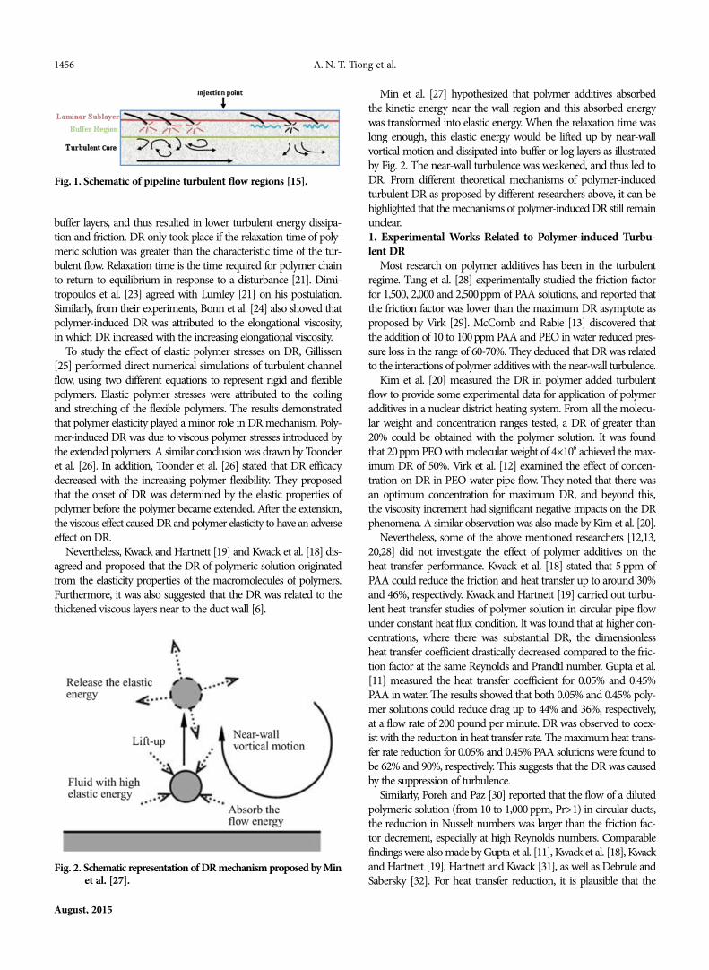
According to Abubakar et al. [15], polymer additives could sup-press the turbulent burst formation in buffer layers, which in turnrestrain the development and distribution of turbulent eddies, asshown in Fig. 1. After drag is reduced, less energy is wasted for tur-bulent random motions and more energy can be used to move thefluid along the pipeline. Lumley [21] postulated that polymer-inducedDR occurred due to the increased extensional viscosity during thestretching of randomly coiled polymers under fluctuating shearrate. Extensional viscosity, also known as elongational viscosity, is aterm used for viscosity, when the extensional stress is applied [22].Higher extensional viscosity dampened the turbulent energy in the
1456 A. N. T. Tiong et al.
August, 2015
buffer layers, and thus resulted in lower turbulent energy dissipa-tion and friction. DR only took place if the relaxation time of poly-meric solution was greater than the characteristic time of the tur-bulent flow. Relaxation time is the time required for polymer chainto return to equilibrium in response to a disturbance [21]. Dimi-tropoulos et al. [23] agreed with Lumley [21] on his postulation.Similarly, from their experiments, Bonn et al. [24] also showed thatpolymer-induced DR was attributed to the elongational viscosity,in which DR increased with the increasing elongational viscosity.
To study the effect of elastic polymer stresses on DR, Gillissen[25] performed direct numerical simulations of turbulent channelflow, using two different equations to represent rigid and flexiblepolymers. Elastic polymer stresses were attributed to the coilingand stretching of the flexible polymers. The results demonstratedthat polymer elasticity played a minor role in DR mechanism. Poly-mer-induced DR was due to viscous polymer stresses introduced bythe extended polymers. A similar conclusion was drawn by Toonderet al. [26]. In addition, Toonder et al. [26] stated that DR efficacydecreased with the increasing polymer flexibility. They proposedthat the onset of DR was determined by the elastic properties ofpolymer before the polymer became extended. After the extension,the viscous effect caused DR and polymer elasticity to have an adverseeffect on DR.
Nevertheless, Kwack and Hartnett [19] and Kwack et al. [18] dis-agreed and proposed that the DR of polymeric solution originatedfrom the elasticity properties of the macromolecules of polymers.Furthermore, it was also suggested that the DR was related to thethickened viscous layers near to the duct wall [6].
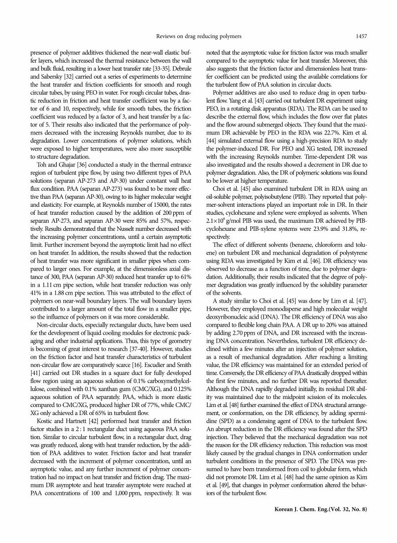
Min et al. [27] hypothesized that polymer additives absorbedthe kinetic energy near the wall region and this absorbed energywas transformed into elastic energy. When the relaxation time waslong enough, this elastic energy would be lifted up by near-wallvortical motion and dissipated into buffer or log layers as illustratedby Fig. 2. The near-wall turbulence was weakened, and thus led toDR. From different theoretical mechanisms of polymer-inducedturbulent DR as proposed by different researchers above, it can behighlighted that the mechanisms of polymer-induced DR still remainunclear.1. Experimental Works Related to Polymer-induced Turbu-lent DR
Most research on polymer additives has been in the turbulentregime. Tung et al. [28] experimentally studied the friction factorfor 1,500, 2,000 and 2,500 ppm of PAA solutions, and reported thatthe friction factor was lower than the maximum DR asymptote asproposed by Virk [29]. McComb and Rabie [13] discovered thatthe addition of 10 to 100 ppm PAA and PEO in water reduced pres-sure loss in the range of 60-70%. They deduced that DR was relatedto the interactions of polymer additives with the near-wall turbulence.
Kim et al. [20] measured the DR in polymer added turbulentflow to provide some experimental data for application of polymeradditives in a nuclear district heating system. From all the molecu-lar weight and concentration ranges tested, a DR of greater than20% could be obtained with the polymer solution. It was foundthat 20ppm PEO with molecular weight of 4×10⁶ achieved the max-imum DR of 50%. Virk et al. [12] examined the effect of concen-tration on DR in PEO-water pipe flow. They noted that there wasan optimum concentration for maximum DR, and beyond this,the viscosity increment had significant negative impacts on the DRphenomena. A similar observation was also made by Kim et al. [20].
Nevertheless, some of the above mentioned researchers [12,13,20,28] did not investigate the effect of polymer additives on theheat transfer performance. Kwack et al. [18] stated that 5 ppm ofPAA could reduce the friction and heat transfer up to around 30%and 46%, respectively. Kwack and Hartnett [19] carried out turbu-lent heat transfer studies of polymer solution in circular pipe flowunder constant heat flux condition. It was found that at higher con-centrations, where there was substantial DR, the dimensionlessheat transfer coefficient drastically decreased compared to the fric-tion factor at the same Reynolds and Prandtl number. Gupta et al.[11] measured the heat transfer coefficient for 0.05% and 0.45%PAA in water. The results showed that both 0.05% and 0.45% poly-mer solutions could reduce drag up to 44% and 36%, respectively,at a flow rate of 200 pound per minute. DR was observed to coex-ist with the reduction in heat transfer rate. The maximum heat trans-fer rate reduction for 0.05% and 0.45% PAA solutions were found tobe 62% and 90%, respectively. This suggests that the DR was causedby the suppression of turbulence.
Similarly, Poreh and Paz [30] reported that the flow of a dilutedpolymeric solution (from 10 to 1,000 ppm, Pr>1) in circular ducts,the reduction in Nusselt numbers was larger than the friction fac-tor decrement, especially at high Reynolds numbers. Comparablefindings were also made by Gupta et al. [11], Kwack et al. [18], Kwackand Hartnett [19], Hartnett and Kwack [31], as well as Debrule andSabersky [32]. For heat transfer reduction, it is plausible that the
Fig. 1. Schematic of pipeline turbulent flow regions [15].
Fig. 2. Schematic representation of DR mechanism proposed by Minet al. [27].
Reviews on drag reducing polymers 1457
Korean J. Chem. Eng.(Vol. 32, No. 8)
presence of polymer additives thickened the near-wall elastic buf-fer layers, which increased the thermal resistance between the walland bulk fluid, resulting in a lower heat transfer rate [33-35]. Debruleand Sabersky [32] carried out a series of experiments to determinethe heat transfer and friction coefficients for smooth and roughcircular tubes, by using PEO in water. For rough circular tubes, dras-tic reduction in friction and heat transfer coefficient was by a fac-tor of 6 and 10, respectively, while for smooth tubes, the frictioncoefficient was reduced by a factor of 3, and heat transfer by a fac-tor of 5. Their results also indicated that the performance of poly-mers decreased with the increasing Reynolds number, due to itsdegradation. Lower concentrations of polymer solutions, whichwere exposed to higher temperatures, were also more susceptibleto structure degradation.
Toh and Ghajar [36] conducted a study in the thermal entranceregion of turbulent pipe flow, by using two different types of PAAsolutions (separan AP-273 and AP-30) under constant wall heatflux condition. PAA (separan AP-273) was found to be more effec-tive than PAA (separan AP-30), owing to its higher molecular weightand elasticity. For example, at Reynolds number of 15000, the ratesof heat transfer reduction caused by the addition of 200 ppm ofseparan AP-273, and separan AP-30 were 85% and 57%, respec-tively. Results demonstrated that the Nusselt number decreased withthe increasing polymer concentrations, until a certain asymptoticlimit. Further increment beyond the asymptotic limit had no effecton heat transfer. In addition, the results showed that the reductionof heat transfer was more significant in smaller pipes when com-pared to larger ones. For example, at the dimensionless axial dis-tance of 300, PAA (separan AP-30) reduced heat transfer up to 61%in a 1.11 cm pipe section, while heat transfer reduction was only41% in a 1.88 cm pipe section. This was attributed to the effect ofpolymers on near-wall boundary layers. The wall boundary layerscontributed to a larger amount of the total flow in a smaller pipe,so the influence of polymers on it was more considerable.
Non-circular ducts, especially rectangular ducts, have been usedfor the development of liquid cooling modules for electronic pack-aging and other industrial applications. Thus, this type of geometryis becoming of great interest to research [37-40]. However, studieson the friction factor and heat transfer characteristics of turbulentnon-circular flow are comparatively scarce [16]. Escudier and Smith[41] carried out DR studies in a square duct for fully developedflow region using an aqueous solution of 0.1% carboxymethylcel-lulose, combined with 0.1% xanthan gum (CMC/XG), and 0.125%aqueous solution of PAA separately. PAA, which is more elasticcompared to CMC/XG, produced higher DR of 77%, while CMC/XG only achieved a DR of 65% in turbulent flow.
Kostic and Hartnett [42] performed heat transfer and frictionfactor studies in a 2 : 1 rectangular duct using aqueous PAA solu-tion. Similar to circular turbulent flow, in a rectangular duct, dragwas greatly reduced, along with heat transfer reduction, by the addi-tion of PAA additives to water. Friction factor and heat transferdecreased with the increment of polymer concentration, until anasymptotic value, and any further increment of polymer concen-tration had no impact on heat transfer and friction drag. The maxi-mum DR asymptote and heat transfer asymptote were reached atPAA concentrations of 100 and 1,000 ppm, respectively. It was
noted that the asymptotic value for friction factor was much smallercompared to the asymptotic value for heat transfer. Moreover, thisalso suggests that the friction factor and dimensionless heat trans-fer coefficient can be predicted using the available correlations forthe turbulent flow of PAA solution in circular ducts.
Polymer additives are also used to reduce drag in open turbu-lent flow. Yang et al. [43] carried out turbulent DR experiment usingPEO, in a rotating disk apparatus (RDA). The RDA can be used todescribe the external flow, which includes the flow over flat platesand the flow around submerged objects. They found that the maxi-mum DR achievable by PEO in the RDA was 22.7%. Kim et al.[44] simulated external flow using a high-precision RDA to studythe polymer-induced DR. For PEO and XG tested, DR increasedwith the increasing Reynolds number. Time-dependent DR wasalso investigated and the results showed a decrement in DR due topolymer degradation. Also, the DR of polymeric solutions was foundto be lower at higher temperature.
Choi et al. [45] also examined turbulent DR in RDA using anoil-soluble polymer, polyisobutylene (PIB). They reported that poly-mer-solvent interactions played an important role in DR. In theirstudies, cyclohexane and xylene were employed as solvents. When2.1×106 g/mol PIB was used, the maximum DR achieved by PIB-cyclohexane and PIB-xylene systems were 23.9% and 31.8%, re-spectively.
The effect of different solvents (benzene, chloroform and tolu-ene) on turbulent DR and mechanical degradation of polystyreneusing RDA was investigated by Kim et al. [46]. DR efficiency wasobserved to decrease as a function of time, due to polymer degra-dation. Additionally, their results indicated that the degree of poly-mer degradation was greatly influenced by the solubility parameterof the solvents.
A study similar to Choi et al. [45] was done by Lim et al. [47].However, they employed monodisperse and high molecular weightdeoxyribonucleic acid (DNA). The DR efficiency of DNA was alsocompared to flexible long chain PAA. A DR up to 20% was attainedby adding 2.70 ppm of DNA, and DR increased with the increas-ing DNA concentration. Nevertheless, turbulent DR efficiency de-clined within a few minutes after an injection of polymer solution,as a result of mechanical degradation. After reaching a limitingvalue, the DR efficiency was maintained for an extended period oftime. Conversely, the DR efficiency of PAA drastically dropped withinthe first few minutes, and no further DR was reported thereafter.Although the DNA rapidly degraded initially, its residual DR abil-ity was maintained due to the midpoint scission of its molecules.Lim et al. [48] further examined the effect of DNA structural arrange-ment, or conformation, on the DR efficiency, by adding spermi-dine (SPD) as a condensing agent of DNA to the turbulent flow.An abrupt reduction in the DR efficiency was found after the SPDinjection. They believed that the mechanical degradation was notthe reason for the DR efficiency reduction. This reduction was mostlikely caused by the gradual changes in DNA conformation underturbulent conditions in the presence of SPD. The DNA was pre-sumed to have been transformed from coil to globular form, whichdid not promote DR. Lim et al. [48] had the same opinion as Kimet al. [49], that changes in polymer conformation altered the behav-iors of the turbulent flow.

1458 A. N. T. Tiong et al.
August, 2015
Sohn et al. [50] conducted experiments in a rotating disk flowto study DR of XG. From these experiments, XG was found to bean effective drag reducer for high temperature applications. XG de-monstrated a higher DR at 50-60 oC compared to the DR obtainedat room temperature. This was because as at high temperature,XG transformed from a helical structure to individual coil, whichwas a better polymer conformation for DR. Moreover, DR achievedby the addition of XG increased with its concentration until maxi-mum DR was attained.
Kim et al. [51] investigated the turbulent DR characteristic ofpolysaccharide guar gum with RDA, and then compared the resultswith those obtained using PEO. Although, PEO, a synthetic water-soluble drag reducing polymer, was more effective for DR, it de-graded faster when compared to guar gum. DR efficiency of thePEO solution dropped more than 10% after the first 10 minutes ina rotating disk flow, while guar gum exhibited significant resistanceto mechanical stress.
A mixture of polymer and surfactant is also believed to be a gooddrag reducer. Kim et al. [49] further explored the effect of pH andsurfactant on the DR efficiency of polymer additives in open tur-bulent flow by using RDA. An illustration of the conformationalvariation of PAA molecular at different pH levels is given in Fig. 3.Their results showed that at pH 11, the DR efficiency was higher
compared to that at pH of 4 and 7. Therefore, they postulated thata highly extended polymer conformation was more favorable forDR in turbulent flow. DR increased with the increasing surfactantconcentration, as shown in Fig. 4. As presented in Fig. 5, interac-tion between surfactant and polymer chains enhanced the bond-ing force of polymer molecules, and stretched the polymer chains,thus leading to higher DR, especially at lower pH levels. From thework done by Kim et al. [49], it can be deduced that a mixture ofpolymer and surfactant serves as a better drag reducer comparedto a pure polymer solution.
Matras et al. [52] indicated that the mixed PEO and cetyltrimethylammonium bromide (CTAB) solution may serve as a drag reducerin pipe flow. When polymer and surfactant were mixed in water,aggregates were formed in which polymer film encircles the micelle.This mixed polymer-surfactant solution showed a higher DR thanpure polymer and surfactant solutions. Moreover, this mixed sys-tem resisted shear rate better than that of individual substancesalone, as it took longer for the mixed solution to degrade. The dam-aged aggregates were partly self-repaired.
In different studies, Mohsenipour and Pal [53] examined the tur-bulent DR behavior of mixed nonionic polymer and cationic sur-factant solution. PEO and octadecyltrimethyl ammonium chlo-ride (OTAC) were used in their experiments. Experimental resultsshowed that this mixed polymer-surfactant solution gave a higherDR when compared to a pure polymer or pure surfactant solution.This synergistic effect was also found to be more significant at lowpolymer concentrations and high surfactant concentrations. Therates of DR achieved by the mixed polymer-surfactant solutionwere 58% and 35% higher as compared to the pure surfactant andpure polymer solutions, respectively. It was hypothesized that theDR was caused by the new three-dimensional microstructure. Thismicrostructure was formed when the micelle of the surfactant wasattached to the polymer chain and it could suppress the turbulenceeddies.2. CFD Studies Related to Polymer-induced Turbulent DR
Numerical investigations have also been conducted by research-ers to study polymer-induced DR. Dimitropoulos et al. [23] uti-lized the FENE-P model and Giesekus model in their numericalsimulations of turbulent channel flow of a polymer solution, and
Fig. 3. Illustration of PAA conformation at different pH levels [49].
Fig. 4. DR as a function of polymer concentration (pH=4) with var-ious sodium dodecyl sulfate (SDS) concentration [49].
Fig. 5. Illustration of PAA conformation after adding surfactantSDS [49].

Reviews on drag reducing polymers 1459
Korean J. Chem. Eng.(Vol. 32, No. 8)
Tabl
e1.S
umm
ary
of C
FD st
udie
s rela
ted
to p
olym
eric
solu
tion
Auth
orG
eom
etry
Flow
regi
me
Type
s of p
olym
erus
edM
odel
used
for
simul
ation
Rem
arks
Shin
and
Cho
[38]
2:1
Rect
angu
lardu
ct
Lam
inar
-W
ith h
eat t
rans
fer-
Cons
tant
axial
hea
t flu
x-
Cons
tant
per
iphe
ral w
all
tempe
ratu
re (t
op-w
all
heate
d wi
th al
l oth
ers a
di-
abati
c)
1,000
ppm
PAA
(sepa
ran
AP-2
73)
Carr
eau
mod
el wi
th fl
uid
prop
erty
of
tempe
ratu
rede
pend
ent a
nd sh
ear t
hin-
ning
visc
osity
•Co
mpa
red
to c
onsta
nt p
rope
rty, u
sing
tempe
ratu
re d
epen
dent
and
shea
r th
inni
ng v
iscos
ity m
odel
coul
d be
tter
pred
ict th
e he
at tra
ns-
fer p
erfo
rman
ce o
f PAA
solu
tion.
•Th
e N
usse
lt nu
mbe
r wa
s en
hanc
ed b
y 70
-300
% c
ompa
red
to th
eon
e usin
g co
nsta
nt fl
uid
prop
erty.
•H
eat t
rans
fer e
nhan
cem
ent w
as d
ue to
the
incr
easin
g of
nea
r-wall
velo
city
grad
ient f
rom
the
com
bine
d eff
ect o
f tem
pera
ture
dep
en-
dent
and
shea
r thi
nnin
g vi
scos
ity.
Nac
cach
e and
Men
des [
59]
Rect
angu
lardu
ct (w
ith
duct
aspe
ct ra
tio o
f 1, 2
&
4)
Lam
inar
-W
ith h
eat t
rans
fer-
Top
and
botto
m w
all
unde
r con
stant
hea
ting
and
side w
alls a
diab
atic
Non
-New
toni
an
visco
elasti
c sol
u-tio
n (th
e typ
e of
non-
Newt
onia
n so
lutio
n is
not
men
tione
d)
Crim
inale
-Eric
ksen
-Fil-
bey
(CEF
)•
The
pres
ence
of s
econ
dary
flow
did
not
hav
e an
y eff
ect o
n fri
ctio
nfa
ctor.
•Se
cond
ary
flow
enha
nced
the
Nus
selt
num
ber
of n
on-N
ewto
nian
solu
tion
up th
ree
times
larg
er th
an r
elativ
e N
ewto
nian
flow
. Effe
ctof
sec
onda
ry f
low
on h
eat
trans
fer e
nhan
cem
ent
was
dom
inan
tco
mpa
red
to im
pact
of sh
ear t
hinn
ing
visco
sity.
•Fo
r m
axim
um h
eat
trans
fer p
erfo
rman
ce,
ther
e ex
isted
an
opti-
mum
com
bina
tion
of as
pect
ratio
and
Reyn
olds
num
ber.
Dim
itrop
oulo
set
al. [2
3]Ch
anne
lTu
rbul
ent
-W
ithou
t hea
t tra
nsfer
-Co
nsta
nt p
ressu
re g
radi
ent
Dilu
te an
d co
n-ce
ntra
tion
poly-
mer
solu
tion
FEN
E-P
& G
iesek
us
mod
el•
DR
was a
ttrib
uted
to th
e ext
ensio
nal v
iscos
ity o
f the
pol
ymer
.•
Whe
n th
e ex
tensib
ility
visc
osity
of
the
polym
er i
ncre
ased
, trip
lein
crem
ent i
n D
R wa
s obs
erve
d.M
in et
al. [
27]
Chan
nel
Turb
ulen
t-
With
out h
eat t
rans
fer-
Cons
tant
mas
s flo
w ac
ross
chan
nel
Polym
er so
lutio
nO
ldro
yd-B
mod
el•
Polym
er a
bsor
bed
the
turb
ulen
t kin
etic
ener
gy n
ear t
he w
all, t
rans
-fo
rmed
them
to e
lastic
ene
rgy
and
trans
porte
d th
em to
buf
fer la
y-er
s. Th
is in
terve
ned
turb
ulen
t ene
rgy
trans
fer an
d led
to D
R.•
Relax
ation
tim
e m
ust b
e lo
ng e
noug
h fo
r D
R to
occ
ur a
s di
ssipa
-tio
n of
elas
tic en
ergy
nea
r wall
to b
uffer
laye
rs ne
eded
tim
e.Pt
asin
ski e
t al.
[54]
Chan
nel
Turb
ulen
t-
With
out h
eat t
rans
fer-
Cons
tant
pre
ssure
dro
p
Polym
er so
lutio
nFE
NE-
P m
odel
•St
retch
ing
of p
olym
ers w
as n
eces
sary
for D
R.•
Dur
ing
DR,
velo
city
fluctu
ation
s de
crea
sed
and
mov
ed a
way
from
wall.
•FE
NE-
P m
odel
coul
d no
t ful
ly re
pres
ent t
he rh
eolo
gica
l beh
avio
r of
polym
er so
lutio
n.D
hotre
et al
.[5
6]Pi
peTu
rbul
ent
-W
ithou
t hea
t tra
nsfer
PAA,
XG
, CM
C,
and
blen
d of
XG
/CM
C so
lutio
n
Low
Reyn
olds
num
ber
k-ε m
odel
•Lo
w Re
ynol
ds n
umbe
r k-ε
mod
el co
uld
be u
sed
to c
ater t
he li
quid
and
turb
ulen
t velo
cities
for d
rag
redu
cing
fluid
s qui
te ac
cura
tely.

1460 A. N. T. Tiong et al.
August, 2015
compared both of the results obtained. The results demonstratedthat the onset of DR took place at a certain critical Weissenbergnumber. Both the Giesekus model and the FENE-P simulationsreached the same conclusion that the DR was due to the exten-sional viscosity.
Min et al. [27] employed a numerical model to simulate and studythe DR mechanism of polymer additives in turbulent channel flow.An Oldroyd-B model (linear Hookean dumbbells) was used to rep-resent the linear elastic behaviors of the polymer additives. Min etal. [27] pointed out that there was a threshold of the Weissenbergnumber for DR to occur. For a Reynolds number of 15000, andthe Weissenberg number of 2, DR up to 28% could be obtained.
Ptasinski et al. [54] also used the FENE-P model to observe theelastic behavior of polymers in turbulent channel flow. It was ob-served that with increasing DR, the buffer layers were considerablythickened. Moreover, spanwise and wall-normal velocity fluctua-tions were shifted away from the wall monotonically during higherDR.
In contrast, Lagrangian simulations were recommended by Ter-rapon [55] to investigate the DR of a dilute polymer solution inturbulent channel flow. The Lagrangian approach has the ability totrack a large amount of turbulent polymer molecules and computepolymer stress along the flow directions. Therefore, the dynamicsof a single polymer molecule could be described by the simulations.Terrapon [55] proposed a novel numerical technique based on theLagrangian approach to model and simulate the DR. In anotherstudy, Dhotre et al. [56] used CFD simulation to examine the flowpattern of drag reducing fluids in the turbulent pipe flow. They con-cluded that drag reducing fluids could be modeled using the lowReynolds number k-ε model. The low Reynolds number k-ε modelutilized the non-linear viscosity and damping function to take thenear-wall effects into account. It was found that the simulationresults on axial velocity and kinetic energy were in agreement withthe experimental profiles of Escudier et al. [57] and Presti [58].
The CFD related studies are summarized in Table 1. From Table1, there is an absence of proper constitutive equations for solvingpolymers related to the CFD studies. Different researchers use dif-ferent models to represent the behavior of polymers in CFD.
CLASSIFICATION OF DR METHODS
DR methods can be broadly classified into additive and non-additive techniques. Polymers are one of the additive DR techniques.The major non-additive and additive DR methods are shown inFig. 6.1. Riblets
Riblets are longitudinal microgrooves attached to a surface thatresemble the scale pattern of a shark. When a shark is swimming,
Fig. 6. Classification of DR methods.
Fig. 7. V, U and L-shaped riblets [62,63].

Reviews on drag reducing polymers 1461
Korean J. Chem. Eng.(Vol. 32, No. 8)
its skin exhibits riblet structures that align to the flow direction toreduce skin drag [60]. In addition, riblets provide larger surface area,thus promoting higher momentum and heat transfer rate [61]. Rib-lets have different shapes, but the most common designs are V-shaped (triangular), U-shaped (scalloped) and L-groove (rectan-gular) riblets as shown in Fig. 7.
Riblets were first used at NASA Langley Research Centre to reducethe friction of aircraft airflows [64]. Walsh [65] reported that thepresence of riblets reduced a small amount of drag and this con-clusion was in agreement with the preliminary results of Liu et al.[66] who used a longitudinal rectangular ribbed surface. This hasled to further research on the effectiveness of riblets as drag reducer.
Choi et al. [67] studied numerically the effect of riblets in a fullydeveloped laminar channel flow by solving the Poisson equation.They used a W-type multigrid cycle for the spanwise direction andtridiagonal solver for the normal direction. Their results showedthat drag was not reduced in the laminar channel flow. Chu andKarniadakis [68] carried out direct numerical simulations over theriblet-mounted surfaces, covering laminar, transitional and turbu-lent regimes with the Reynolds number ranging from 500 to 3500.The riblets were simulated in the lower wall of the channel usingthe spectral element-Fourier method. Their results were in agree-ment with Choi et al. [67] that no DR was found for the laminarregime. DR was only reported for transitional and turbulent regimes.
Many studies have shown that riblets are capable of reducingthe turbulence intensity up to 6-10% [68-72]. In spite of this, thereis no general consensus on the mechanisms underlying the DR phe-nomena of riblets. Kwing-So Choi [69] and Warsop [70] suggestedthat riblets serve as fences in restricting the stream-wise movementof longitudinal vortices, leading to premature occurrence of burstwith reduced duration and turbulence intensity. Haecheon Choiand his co-workers [71] proposed that riblets reduced drag by lim-iting the streamwise vortices above the wetted riblet surface. Anothertheory claimed that DR by riblets was achieved by viscous interac-tion between the longitudinal vortices and small eddies near theriblets peaks, which in turn produced secondary vortices that damp-ened the longitudinal vortices and maintained low-speed flow through
riblet valleys [73].2. Dimples
Dimples are regular arrangements of discrete indentations milledonto a wall surface, primarily used for heat transfer enhancement(Fig. 8). Alekseev et al. [74] experimentally observed that besidesimproving heat transfer, dimples could reduce turbulent skin-fric-tion up to 20%. However, the underlying mechanisms of DR arestill unexplainable. Most common use of dimples for DR can beseen in golf balls [75,76] where dimples are able to help reducingdrag caused by the air resistance acting against the flow direction.Dimples also increase the lift force in the golf balls.
Lienhart et al. [78] did experiments and direct numerical simu-lations for turbulent flow over dimpled surfaces and reported im-proved heat transfer performance without any significant effect ondrag. Whereas, Kim et al. [79] reported improvement in both heattransfer and drag. They numerically estimated the friction loss andheat transfer of turbulent flow in a cooling channel with staggeredelliptic dimples. The optimized dimple design was found to increaseheat transfer rate by 32.8% and decrease the frictional loss by 34.6%.Silva et al. [80] investigated dimple performance experimentallyand numerically, for constant heat flux boundary condition. Nusseltnumber of dimpled surfaces was higher compared to a flat surface.Moreover, friction also increased with the increasing Reynolds num-ber. Overall performance of dimples was generally good at low Reyn-olds number, as friction was relatively small. Hence, the uses of dim-ples are suggested only for laminar flow application such as in micro-electronic cooling. In addition, Burgess et al. [81] found experimen-tally that dimples enhanced heat transfer performance; however,friction factor ratios increased with the increasing Reynolds num-ber. When Reynolds number increased from 12000 to 70000, thefriction factor ratio also increased from 1.6 to 2.6. Silva et al. [80]and Burgess et al. [81] opined that the use of dimples increasedpressure drop and these results are contradictory to that reportedby Kim et al. [79].
These inconsistent results reported in literature may be attributedto the differences in the geometry of dimples (shapes, depth andspacing) as studied, flow type (internal or external), flow regime(Reynolds number range), measurement techniques and result analy-sis methods. For example, Samad et al. [82] applied the same meth-ods used by Kim et al. [79] in their multi-objective optimization.Their results showed that the heat transfer performance and pres-sure drop of the flow across dimples were affected by dimple depthand spacing. Heat transfer and pressure drop increased with theincrease of dimple depth, but decreased with the increase of dim-ple spacing.
Veldhuis and Vervoort [77] analyzed the DR capabilities of dim-ples, using experiments and large eddy simulation (LES). Experi-mental results pointed out that the shallow dimple (0.343mm≤depth≤0.5 mm) reduced drag, while the deep dimples (1.5 mm≤depth≤3.5 mm) increased drag. For the shallow dimples, 20% DR was re-ported at low flow velocities. Dimples with intermediate depth re-duced drag only at low flow velocities. In contrast, their simula-tion results showed that drag increased for both shallow and deepdimples.3. Oscillating Walls
Oscillating walls is a technique in which one or two walls areFig. 8. A dimpled surface [77].

1462 A. N. T. Tiong et al.
August, 2015
subjected to motor-driven forced spanwise or streamwise oscilla-tion [61]. Most studies are conducted on spanwise oscillating wallsas shown in Fig. 9. Oscillating walls were developed based on theconcept that the turbulent phenomenon can be suppressed whena sudden spanwise pressure gradient is applied on the near-wallturbulent flow field. There is a common agreement that wall oscil-lation at suitable velocity, frequency and amplitude promotes DR.This is because the oscillation alters the near-wall boundary layers,and thus reduces the turbulence intensity [83-89].
The first spanwise wall oscillation was studied by Jung et al. [91].They used direct numerical simulation to investigate the spanwiseoscillation of wall-bound turbulent flow and reported a DR of 10to 40%. The maximum drop in turbulence intensity was found tobe 35%. Fang et al. [84] simulated the turbulent channel flow withspanwise wall oscillation and modeled it using LES to inspect theeffects of the oscillating walls. It was found that a maximum DR of46% could be attained.
Baron and Quadrio [85] in their numerical simulations of Navier-Stokes equations for a plane channel flow with spanwise wall oscil-lation, obtained up to 40% turbulent DR. They also claimed thatthe energy saved in the reduction of friction could be counter-bal-anced by the power supplied to sustain the oscillating walls, partic-ularly at low wall-oscillation amplitude and velocity. Ten percent netpower saving was observed. Quadrio and Ricco [92] also foundthat a maximum net energy saving of approximately 7.3-10%, alongwith 44.7% maximum DR, could be achieved using oscillating walls.
Laadhari et al. [86] experimentally investigated the turbulenceboundary layers on a flat plate subjected to spanwise wall oscilla-tion and suggested that skin friction drag could be reduced usingoscillating walls. This suggestion was later proven by Choi et al.[87], Choi and Clayton [88], and Choi [89] in their experiments.Their experimental results showed that 45% skin friction reduc-tion could be attainable at the downstream of spanwise wall oscil-lation. This result agreed closely with those obtained from simulations[84,85,91,92]. These researchers [86-89] agreed that DR is drivenby the spanwise vorticity developed via wall oscillation. This vor-ticity reduced the near-wall mean velocity gradient and aligned thevortices, leading to a drop in turbulent fluctuations.
Choi and Graham [93] experimentally studied DR in a turbu-lent pipe flow by imposing circular-wall oscillation to a section ofthe pipe. The friction factor of the pipe was reduced by 25%. TheDR achieved in pipe flow was much smaller than the DR obtained
in their other research work [87-89] on external flow. It was postu-lated that DR in pipe flow is the result of realignment of longitudi-nal vortices in circumferential direction (direction of the oscillatingwall).4. Compliant Surfaces
Similar to riblets, the idea of compliant surfaces also comes fromthe turbulence control technique of marine organisms. Kramer [94]first observed that dolphins can swim at high speeds because oftheir flexible skin, which has a drag resistant nature. He discov-ered that 60% DR could be achieved by the compliant coatings(Fig. 10) modeled after dolphins’ skin. DR was achieved by delay-ing transition to turbulence. However, the 60% DR obtained byKramer [94] could not be reproduced by other researchers [95-98].
Benjamin [100], Betchov [101], and Landahl [102] performedtheoretical studies on compliant coatings and reported that DR bytransition to turbulence postponement was possible. The early stud-ies by these researchers [100-102] focused on DR by delaying tran-sition to turbulence in laminar boundary layer, but not on reducingturbulent skin friction in turbulent boundary layer using compli-ant surfaces.
Carpenter and Garrad [99] analyzed experiments by Kramer[94] and other researchers [95-98], in order to check the DR capa-bility of Kramer’s coatings. Carpenter and Garrad [99] claimed thatKramer’s coatings were only capable of delaying transition to tur-bulence. The reason that Kramer’s coatings did not perform wellfor these researchers [95-98] might be the differences in the exper-imental conditions. It was difficult to make compliant surfaces, asthe material properties were sensitive to changes. Undesirable fac-tors like poor pressure gradient, or problems in making joints be-tween compliant and rigid surfaces, could affect the performanceof the coatings. Moreover, Kramer’s coatings were also not flexibleenough to be used for higher Reynolds number flows. Therefore,the results from these experiments [95-98] were inconclusive in
Fig. 9. Schematic of spanwise oscillation for channel flow [90].
Fig. 10. Kramer’s coatings and model: (a) cross section, (b) cutthrough stubs, (c) model: shaded regions were coated [94,99].

Reviews on drag reducing polymers 1463
Korean J. Chem. Eng.(Vol. 32, No. 8)
proving that DR achieved by Kramer [94] is irreproducible.In 1991, Kulik et al. [103] used the optimum compliant surfaces
produced by Semenov [104] in their experimental work. They re-ported a successful turbulent DR in a lake and their experimentalresults were validated by Choi et al. [105]. Choi et al. [105] werealso able to demonstrate that compliant surfaces could indeed reduceskin friction for turbulent boundary layers. Skin-friction and near-wall pressure fluctuations were reduced to around 7% and 19%,respectively, in downstream, where the compliant surfaces werefixed. Turbulence intensity was also reduced up to 5%. In addition,the thickness of the viscous sub-layers increased along with turbu-lent DR.
Endo and Himeno [106] performed direct numerical simula-tion of a turbulent duct flow over compliant surfaces. Two to −3%average and 7% maximum DR were achieved with weak wall dis-placement of the compliant surfaces. The DR results obtained byChoi et al. [105] through experiments agreed with the simulationresults of Endo and Himeno [106].
Xu et al. [107] used the incompressible Navier-Stokes equationsto model the fluid motion and the compliant surfaces were modeledas homogeneous spring-supported plates. They did not observeany DR in their simulation results. The differences in results ob-tained by Xu et al. [107] and Endo and Himeno [106] were due tothe different averaging times used in their simulations.
Complexity in compliant surfaces is the reason that most of thepast research done in this area is based on trial and error. Further-more, Choi et al. [105] and Endo and Himeno [106] claimed thatoptimization and the right combination of material properties wasnecessary for compliant surfaces to achieve turbulent DR.5. Microbubbles
Smaller bubbles with a diameter of 10μm are known to be effec-tive for DR [108], whereas larger bubbles with a diameter exceeding500μm tend to lose their DR efficiency [109]. These microbub-bles can be produced in numerous ways, but the most commonmethod is electrolysis. Microbubbles produced by electrolysis areforced through a porous medium as shown in Fig. 11.
The pioneers, McCormick and Bhattacharyya [112], created hy-drogen microbubbles through water electrolysis on a ship hull’s pro-totype, which reduced the viscous drag by 50% by altering the lami-nar and turbulent boundary layers. Microbubbles then gained muchinterest in the research field. Microbubbles could reduce the fric-tion drag in the turbulent boundary layers by as much as 80% [113].When the viscosity of microbubbles increased, the interaction be-tween fluid and these bubbles was enhanced. As a result, Reyn-olds stress decreased, leading to reduction in near-wall velocity
gradient, viscosity and density of the gas-liquid flow, hence dragwas reduced [111].
Madavan et al. [114] performed numerical investigations on mi-crobubbles DR over a flat plate using a simple mixing-length modelfor turbulence. DR up to 50% was obtained. The degree of DR wasfound to depend on the size and concentration of the bubbles, bub-ble dynamics, as well as the location of the injection and distribu-tions of bubbles [114,115].
Most of the research on microbubbles has been done for exter-nal flow such as the flow over a flat plate, towed vehicle or ship [114,116]. As for internal flow, the DR was attainable only for a limiteddistance after the injection point, as the bubbles coalesced and formedlarger bubbles [109,117]. Afiza and Okanaga [109] observed thatfor the velocity range of 0.5-0.9 m/s, bubbles grew larger with time,and thus increased the friction loss in the pipe. They also concludedthat bubble coalescence and size growth were affected by fluid veloc-ity and pipe diameter. A trade-off between fluid velocity and pipediameter might prevent bubble coalescence and size growth foroptimal DR. Nevertheless, more investigations on a method to pre-vent bubble coalescence and size growth should be carried out. Fur-thermore, Xu et al. [117] did direct numerical simulation of turbulentchannel flow using small spherical bubbles of average void frac-tion of 8%. Their findings were consistent with Kawamura et al.[108] that smaller bubbles produced sustained DR over time com-pared to larger bubbles. Larger bubbles only reduced drag for a shorttime before they increased drag. Kodama [118] studied the effectof microbubbles on skin friction reduction in pipe flow, and reportedDR up to 40%. Wu et al. [119] managed to get 21.6% microbub-bles DR in a channel flow.6. Fiber
Forrest and Grierson [120] were the first to study the reductionof energy loss in a turbulent pipe flow using wood-pulp fiber-watersuspensions. Asbestos, nylon, acrylic and glass fibers were also re-ported to suppress turbulence in suspensions. Asbestos fibers arehair-like and long, while nylons are generally of aspect ratio (lengthto diameter ratio) of 50 [6].
Fibers varied the velocity profile of the flow, thus then reducingthe wall shear stress and lowering the flow resistance [121]. On theother hand, Lee and Duffy [122] discovered that the near-wall flowbehavior was unaffected by the presence of fibers, and they pro-posed that the DR by fibers was due to the turbulence suppressionin the turbulent core region.
Fibers with an aspect ratio of 25-35 were found to be effectiveat high concentration [6,123,124]. DR generally increased with theincreasing fiber concentration. It was reported that 100ppm of asbes-
Fig. 11. (a) Schematic of a microbubbles generator [110], (b) microbubbles generated [111].

1464 A. N. T. Tiong et al.
August, 2015
tos could reduce drag by 2%; while by increasing the concentra-tion to 5,000 ppm, a DR of 70% could be achieved. Moreover, fiberswith a higher aspect ratio, flexibility and surface roughness pro-duced better DR. For two fibers with the same aspect ratio, the onewith smaller diameter gave more DR, as flexibility increased withshort diameter fibers [125]. Generally, it can be concluded that fiberswith shorter diameter, higher aspect ratio and concentration, pro-duce better DR.
Moyls and Sabersky [126] obtained a friction reduction by a fac-tor of 3 for 300 ppm asbestos in a smooth pipe. Paschkewitz et al.[127] numerically studied turbulent DR using rigid fibers and re-ported a DR of up to 26%. When drag was reduced, Reynolds stresses,velocity fluctuation in the wall-normal and spanwise directions,and streamwise vorticity were also reduced, whereas streamwisefluctuations were increased. The results also showed that the elas-tic property was not essential for turbulent DR.7. Surfactants (Surface Active Agents)
DR using an anionic surfactant, aluminium disoap was first dis-covered by Mysels [128] in 1949. Surfactants can be classified intotwo main classes of nonionic (undissociated) and ionic surfactants.Ionic surfactant can be further grouped into anionic (negative charge),cationic (positive charge) and zwitterionic (both positive and nega-tive charges) surfactants. Surfactants align themselves into assem-blies known as micelles, due to their polarity if the critical micelleconcentration is reached [129].
Tamano et al. [130] studied the drag reducing ability of ARO-MOX, a nonionic surfactant, and found that with 500 ppm of it,DR ratio of 50%, and larger than 60% could be achieved in the tur-bulent boundary layer flow and pipe flow, respectively. It was alsoreported that the turbulence was suppressed and near-wall vorti-ces were modified by the addition of AROMOX. For anionic sur-factant like aluminium dioleate, a higher concentration of 7,500ppm was required for DR to occur compared to other types of sur-factants [131]. Moreover, a cationic surfactant, hexadecyltrimethylammonium chloride with sodium salicylate could reduce the dragof a rough pipe flow up to 73.7% [132]. As for zwitterionic surfac-tants, Wei et al. [133] found that a mere 200 ppm of oleyl trimethylaminimide could reduce drag up to 83%.
Krope and Lipus [134] developed a mathematical model for theoptimization of pipeline and pumps in heating and cooling sys-tems with surfactants, and reported 80% DR. Yu and Kawaguchi[135] in their direct numerical simulation of surfactants in a chan-nel, reported a maximum DR of 53.2%.
Yu et al. [136] performed experiments and direct numerical sim-ulation with the Giesekus model for cetyltrimethyl ammoniumchloride (CTAC) surfactant solution in a channel. They observeda dual effect of surfactants on frictional drag. Surfactants introduceda viscoelastic shear stress that increased the frictional drag, while atthe same time, surfactants also dampened the turbulent eddies, de-creased the turbulent shear stress, and thus decreased the frictionaldrag. The latter effect was larger than the former, so overall, it ledto DR.
DR was caused by the shear-induced structures (SIS) of the sur-factant solution [137-139]. Hu and Matthys [138] looked into theSIS structure of tris (2 hydroxyethyl) tallowalkyl ammonium ace-tate (TTAA) surfactant solution. The results indicated that the SIS
recovered after shear. It took a longer time for the SIS to reformwhen a higher shear rate was applied to the surfactant solution.
Zhang et al. [140] examined the DR characteristic of the CTACsurfactant solution in a turbulent channel flow, and compared itsrheological characteristic with macroscopic behavior, to get an insightinto the DR mechanism. For higher surfactant concentration, theyobserved a sudden increase in surfactant shear viscosity, after theinitial decrease when the critical shear rate was reached. This showedthe existence of SIS. However, these types of results were not ob-tained for concentrations lower than 90 ppm. They concluded thatSIS was not necessary for surfactant DR. This conclusion was con-tradictory to those from Bewersdorff and Ohlendorf [137], Hu andMatthys [138] and Kim et al. [139].
Kim et al. [139] experimentally investigated the time dependentDR ability of the Habon-G surfactant solution. When the surfac-tant solution was subjected to a highly turbulent flow, there was agreat reduction in its DR ability after a period of time as in Fig. 12.They termed this phenomenon as ‘break down’. SIS for DR couldnot be formed in the broken-down solution. As illustrated in Fig.13, before the breakdown, the surfactant solution was homogeneousbut with some transparent undissolved parts. Large particles wereidentified after the breakdown and more of these particles wereobserved after more shearing was applied to the solution. Theseparticles were believed to be aggregates of surfactant molecules. Itwas postulated that the phenomenon of breakdown was caused bythe loss of effective micelle concentration, due to the precipitationof surfactants and the reaction with molecules of dissolved oxygen.
Degradation of surfactant was also discovered by Qi et al. [141].They checked the DR ability of zwitterionic/anionic surfactant solu-tion after subjecting it to 60 hours of mechanical shear. Althoughsurfactant has self-repair ability after shear, it was found that thesurfactant solution lost it DR efficiency completely at 70. oC Signif-icant loss of DR capability was also observed for the combinationof lower temperature, and high Reynolds number range.8. Comparison between Drag Reducing Methods
DR through additives is the widely preferred method owing toits simplicity. No installation and maintenance costs are involved
Fig. 12. Experimental results obtained by Kim et al. [139] from apilot scale equipment for 200 ppm of Habon-G surfactantsolution.

Reviews on drag reducing polymers 1465
Korean J. Chem. Eng.(Vol. 32, No. 8)
as there are for riblets, dimples, oscillating walls, compliant sur-faces and microbubbles. However, the non-additive DR methodsare environmentally friendly, while drag reducing additives are toxicand environmental pollutants. In addition, DR through additivesis not suitable for industries such as pharmaceutical and food pro-cessing, where fluid properties and parameters are essential for prod-uct quality. To apply drag reducing additives in these industries,additional stages are required. These additional stages might be costlyand hence nullify the cost savings of additives. Although polymeradditives might not be suitable for some industries, there is still awide range of possible applications, especially in gas-liquid and liq-uid-liquid flow systems. Polymer additives have been proposed forapplications such as oil field operations, slurry or hydraulic cap-sule pipeline transportation, suppression of atherosclerosis, preven-tion of lethality from hemorrhagic shock, increased water flow andwater jet focusing in fire-fighting equipment, prevention of over-flow in sewage systems, hydropower and irrigation systems, and asanti-misting agent in jet fuel [129].
In terms of DR performance, all the DR methods are found toreduce drag to some extent. Cheng et al. [142] recommended poly-mer additives as the most effective way of DR, even though otherDR methods have been proven to work as well. To achieve simi-lar turbulent DR as polymer additives, higher concentrations offibers, ionic and nonionic surfactants are required, where the poly-mer can offer drag decrement of 80% just by a few parts per mil-
lion (ppm) of it. Nevertheless, the serious drawback of polymeradditives is that they tend to degrade and lose their effectivenessunder high shear (increases with the increasing Reynolds num-ber) and temperature. Mechanical degradation of polymer is mostlyencountered for flow in a very long channel, or closed loop, withmultiphase cycle through pumps. Surfactants, too, degrade undershear. However, surfactants have rapid self-regenerating ability aftershear. Although surfactants have self-repair ability, they can com-pletely lose their DR efficiency under extreme shear conditions.Moreover, surfactants cause precipitation and foaming. They arealso sensitive to ions present in water.
Among the non-additive DR methods, riblets are the most stud-ied. However, the maximum achievable DR practically is merely8%; this is far lower than what polymers can offer. The DR perfor-mance of polymer additives can be 4-8 times more than riblets.Although a great deal of research has been done on riblets, it is stilldifficult to produce a riblet configuration that can push the DR per-formance past 10%. Dimples are mainly investigated for heat trans-fer enhancement. The suitability of dimples for DR is still uncertain,as mixed results have been reported by researchers. As for compli-ant surfaces, it involves complex issues in modeling and makingthem, thus more work needs to be done before they can be imple-mented for good DR performance. Oscillating walls can be an optionfor DR, but the process involved for installation and maintenanceis complex. Microbubbles can reduce drag more than other non-
Fig. 13. Microphotographs of Habon-G surfactant solution [139]: (a) 1,000 ppm of fresh Habon-G solution, (b) before break down, (c)just after break down, (d) broken-down solution after more shearing.

1466 A. T. N. Tze et al.
August, 2015
Tabl
e2.T
able
of co
mpa
rison
bet
ween
diff
eren
t dra
g re
ducin
g m
etho
dsD
R m
etho
dsAd
vant
ages
Disa
dvan
tage
s
Ribl
ets
•M
axim
um ac
hiev
able
DR
repo
rted
is up
to 1
0%.
•Ea
sy to
be u
sed
[61]
.•
Requ
ire li
ttle o
r eve
n no
main
tenan
ce p
roce
ss [6
1].
•En
viron
men
tal f
riend
ly.
•Th
eore
tical
DR
by ri
blets
is in
the o
rder
of 1
0%, b
ut ri
blets
can
only
achi
eve 5
-8%
DR
prac
ticall
y [7
0].
•Co
st fo
r res
tructu
ring
pipe
or d
uct t
o fix
in ri
blets
is ex
pens
ive.
•In
accu
rate
riblet
s co
nfig
urati
on c
an le
ad to
dra
g in
crem
ent.
It is
com
plex
to c
reate
a r
iblet
con
figur
ation
that
prod
uces
satis
facto
ry D
R pe
rform
ance
[61]
.•
Ther
e is n
o ge
nera
l agr
eem
ent o
n th
e DR
mec
hani
sms o
f rib
lets.
•Fa
ctors
affec
ting
the r
iblet
s DR
such
as ri
blets
spac
ing
are p
oorly
und
ersto
od [6
1].
Dim
ples
•Ca
pabl
e to
redu
ce d
rag
by 3
5% is
repo
rted
in li
tera-
ture
.•
Envir
onm
enta
l frie
ndly.
•M
ost w
ork
done
for d
impl
es is
for h
eat t
rans
fer en
hanc
emen
t stu
dies
and
not o
n D
R.•
Resu
lt on
DR
was n
ot co
nsist
ent a
s the
geo
met
ry o
f dim
ples
stud
ied, f
luid
initi
al co
nditi
on, r
esul
t mea
sure
-m
ent a
nd an
alysis
met
hod
are d
iffer
ent.
•D
R ac
hiev
able
by d
impl
es is
small
and
even
neg
ligib
le. It
is d
ebata
ble i
n lit
eratu
re w
heth
er d
impl
es ar
e sui
t-ab
le to
be u
sed
for D
R.
Osc
illati
ngwa
lls
•M
axim
um ac
hiev
able
DR
repo
rted
is up
to 4
6%.
•N
et en
ergy
savi
ng b
y 7.3
-10%
.•
Envir
onm
enta
l frie
ndly.
•In
stalla
tion
and
main
tenan
ce p
roce
sses
are c
ompl
ex [6
1].
Com
plian
tsu
rface
s•
Max
imum
achi
evab
le D
R re
porte
d is
up to
60%
.•
Envir
onm
enta
l frie
ndly.
•Ca
pabl
e to
redu
ce d
rag
by 6
0% re
porte
d by
Kra
mer
cann
ot b
e rep
rodu
ced
by o
ther
rese
arch
ers.
•It
is co
mpl
ex to
sim
ulate
com
plian
t sur
face
s.
Micr
obub
bles
•M
axim
um ac
hiev
able
DR
repo
rted
is up
to 8
0%.
•Lo
w co
st.•
Envir
onm
enta
l frie
ndly.
•M
icrob
ubbl
es a
re m
ore
suita
ble
prac
ticall
y fo
r D
R in
volvi
ng o
cean
veh
icles
like
shi
ps c
ompa
red
to fl
uid
flow
in p
ipes
[116
].•
For
pipe
flow
, bub
bles
tend
to c
oales
ce a
nd D
R wi
ll di
min
ish. I
n wo
rst c
ase,
drag
mig
ht in
crea
se d
ue to
large
r bub
bles
size
.•
Mec
hani
sms
of m
icrob
ubbl
es D
R an
d qu
antif
icatio
n of
its
effec
t on
DR
are
com
plex
and
inad
equa
tely
unde
rstoo
d [1
09,11
9].
Fibe
rs
•Su
bjec
ted to
less
shea
r de
grad
ation
and
mor
e re
sis-
tant
to
high
stre
ss co
mpa
red
to p
olym
er a
dditi
ves
[5,14
3].
•Le
ss se
nsiti
ve to
tem
pera
ture
and
visc
osity
var
iatio
nof
the s
olve
nt co
mpa
red
to p
olym
er [5
].•
Chem
ically
and
mec
hani
cally
stab
le [1
23].
•Ef
fectiv
e at b
road
er te
mpe
ratu
re ra
nge [
123]
.
•In
duce
plu
ggin
g pr
oblem
s due
to re
quire
men
t of h
igh
conc
entra
tion
for e
fficie
nt D
R [1
23].
•M
ight
alte
r the
phy
sical
and
chem
ical p
rope
rties
of t
he so
lvent
whi
ch m
ake
them
uns
uita
ble
to b
e us
ed in
indu
stries
whi
ch fl
uid
para
mete
rs ar
e im
porta
nt [6
1].

Reviews on drag reducing polymers 1467
Korean J. Chem. Eng.(Vol. 32, No. 8)
Tabl
e2.C
ontin
ued
DR
met
hods
Adva
ntag
esD
isadv
anta
ges
Surfa
ctan
ts
•M
axim
um a
chiev
able
DR
repo
rted
is up
to
80%
[33]
.•
Hav
e se
lf-as
sem
blin
g ab
ility
aft
er
shea
r, so
th
em
icelle
s re
cove
r an
d se
lf re
gene
rate
rapi
dly
after
shea
r if
the
shea
r str
ess
is lo
wer
than
the
crit
ical
shea
r stre
ss [6
1,129
,141]
.•
Wid
ely a
pplie
d in
hea
ting
and
cool
ing
syste
m [
33,
129,1
34,14
4]
•Le
ss att
entio
n is
give
n to
surfa
ctan
t dra
g re
duce
rs a
nd th
ey a
re m
ainly
bein
g us
ed o
nly
for g
as-li
quid
flow
syste
m [1
45,14
6].
•M
ight
alte
r the
phy
sical
and
chem
ical p
rope
rties
of t
he so
lvent
whi
ch m
ake
them
uns
uita
ble
to b
e us
ed in
indu
stries
whi
ch fl
uid
para
mete
rs ar
e im
porta
nt [6
1].
•W
ill st
ill lo
se th
eir D
R ab
ility
if a
criti
cal v
alue o
f Rey
nold
s num
ber a
nd sh
ear s
tress
is ex
ceed
ed [1
41,14
7].
•M
ight
be t
oxic
and
haza
rdou
s to
the e
nviro
nmen
t [14
8].
Noni
onic
surfa
ctant
s•
Chem
ically
stab
le [3
3].
•Lo
w to
xicit
y [3
3].
•Bi
odeg
rada
ble [
33].
•D
o no
t car
ry a
ny c
harg
e an
d th
us c
anno
t hav
e re
actio
n wi
th o
ther
ions
to fo
rm m
icelle
s, lea
ding
to th
eirre
strict
ed ap
plica
tions
[129
].•
Onl
y eff
ectiv
e as d
rag
redu
cers
at n
arro
w tem
pera
ture
rang
e and
conc
entra
tion
[144
, 149
-152
].Ca
tioni
c sur
facta
nts
•Ef
fectiv
e dra
g re
duce
r.•
Reco
ver r
apid
ly fro
m sh
ear [
144]
.•
Hav
e wid
er ef
fectiv
e tem
pera
ture
rang
e [14
4].
•En
coun
ter fe
wer p
robl
ems l
ike f
oam
[144
].•
Not
sen
sitive
to
ions
pre
sent
in w
ater
like
calci
uman
d m
agne
sium
ions
[33]
.
•N
ot ea
sily
biod
egra
dabl
e.
Anion
ic su
rfacta
nts
•Kn
own
as th
e on
ly ef
fectiv
e dr
ag re
ducin
g ad
ditiv
esfo
r hyd
roca
rbon
tran
spor
tatio
n sy
stem
s [12
9,153
].•
Mec
hani
cally
stab
le [1
54].
•H
igh
conc
entra
tion
is re
quire
d fo
r be
tter
DR
perfo
rman
ce, r
esul
ting
in la
rger
cos
ts an
d en
viron
men
tal
impa
cts [
131]
.•
Vuln
erab
le to
ions
pre
sent
in ta
p or
sea w
ater l
ike c
alciu
m an
d m
agne
sium
ions
[155
].•
Caus
e pre
cipita
tion
and
foam
[155
].Zw
itter
ionic
surfa
ctant
s•
Hav
e wid
er ef
fectiv
e tem
pera
ture
rang
e [33
].•
Sens
itive
to io
ns p
rese
nt in
wate
r as t
hey
have
bot
h po
sitive
and
nega
tive c
harg
es [3
3].
Polym
ers
•Ca
pabl
e to
redu
ce d
rag
up to
80%
by
low
conc
entra
-tio
n.•
Mos
t stu
died
DR
addi
tives
[5].
•H
ave
been
wid
ely a
pplie
d as
dra
g re
duce
rs in
gas
-liq
uid
and
liqui
d-liq
uid
flow
syste
ms [
156-
163]
.
•Su
bjec
ted to
mec
hani
cal d
egra
datio
n as
their
bon
ds ru
ptur
e an
d th
eir a
bilit
y to
redu
ce d
rag
dim
inish
es a
thi
gh p
umpi
ng sh
ear r
ate es
pecia
lly fo
r clo
sed-
loop
syste
ms.
•Su
bjec
ted to
ther
mal
degr
adati
on es
pecia
lly at
hig
h tem
pera
ture
.•
Mig
ht a
lter t
he p
hysic
al an
d ch
emica
l pro
perti
es o
f the
solve
nt w
hich
mak
e th
em u
nsui
tabl
e to
be
used
inin
dustr
ies w
hich
flui
d pa
ram
eters
are i
mpo
rtant
[61]
.•
Mig
ht b
e tox
ic an
d ha
zard
ous t
o th
e env
ironm
ent [
15,61
].

1468 A. N. T. Tiong et al.
August, 2015
additive DR methods, as shown in Table 2. The maximum reportedDR for microbubbles is 80%, which is comparable with polymeradditives, but the mechanism for DR and quantification of its effecton DR are complex and inadequately understood. In addition, inpipe flow, bubbles tend to coalesce, causing the DR to diminish.Also, drag tends to increase due to larger bubbles size.
Polymer additives are good because of their excellent DR effi-ciency, although they degrade over time. Mechanical degradationis not a good reason to stop using polymer additives for DR. More-over, more investigations have been done on polymer additives ascompared to other DR methods. Therefore, study on polymers isstill a very attractive research field.
LAMINAR HEAT TRANSER ENHANCEMENTBY POLYMER ADDITIVES
1. Experimental Works Related to Laminar Heat Transfer En-hancement of Polymer Additives
Polymer additives behave differently in laminar flow as com-pared to turbulent flow. Polymer additives are found to enhance heattransfer without penalty of increased drag in the fully developedlaminar non-circular flow. Oliver and Karim [8] studied laminarflow heat transfer in flattened tubes using a PAA solution. Flattenedtubes gave higher heat transfer coefficient than a circular tube. Thisincrement was believed to be caused partly by the increment inthe tube-wall shear rate, and partly by the effect of induced sec-ondary flow. Heat transfer coefficient could be increased by over90%, due to the increment in the tube-wall shear rate. Withoutconsidering the effect of increment in the tube-wall shear rate, theheat transfer could be increased by 45%, due to the sole effect ofthe induced secondary flow. Moreover, higher tube-wall shear ratewas found in tubes with higher aspect ratio, which in turn con-tributed to a higher heat transfer coefficient, but at the expense ofa larger drop in pressure. Secondary flow effect became negligibleat higher aspect ratio (5.7), but reached a maximum with the aspectratio of 1.5. The optimum aspect ratio for good heat transfer per-formance, with small penalty in pressure drop, was found to be 1.4.
Mena et al. [9] compared the laminar flow heat transfer of vis-coelastic solution in various pipes, with different cross sectionsunder constant wall temperature boundary condition. They observedthat for a pipe with rectangular cross section, polymer additivesenhanced the heat transfer coefficient of up to 50% when comparedto a circular pipe (Fig. 14). This was due to the development of sec-ondary flow, resulting from normal stress difference. Square andtriangular ducts showed less heat transfer improvement comparedto the rectangular pipes. It was examined that secondary flow hadlittle effect on flow rate for all non-circular ducts studied. Besides,no effect on fluid friction was reported. The presence of second-ary flow in laminar non-circular ducts was observed by severalresearchers [164-167]. Gao [168] remarked that the heat transferenhancement increased with the increasing strength of secondaryflow.
Hartnett and Kostic [10] studied heat transfer characteristicsusing PAA additives in water for a 2 : 1 rectangular channel. Thelocal and mean Nusselt numbers were found to be higher, and thusa larger heat transfer rate than using pure water at the same Rayleigh
number. Hartnett and Kostic [10] agreed with Mena et al. [9] thatthe heat transfer enhancement was due to the secondary flow. Inaddition, the measured pressure drop agreed with the predictionbased on the power law model. Since no flow visualization resultshad been obtained, Hartnett and Kostic [10] concluded that visco-elastic PAA behaved like a purely viscous non-Newtonian fluid inlaminar non-circular flow, and was similar to the case of laminarcircular flow. The elasticity of PAA did not have an appreciableinfluence on pressure drop; thus the friction factor behavior remainedundisturbed. Kostic [6] hypothesized that the reason for no incre-ment in the friction might be due to the secondary flow, which wasin the transverse direction.
Xie and Hartnett [169] conducted experiments using carbopol934 (polyacrylic acid) and PAA (separan AP-273) in a 2 : 1 rectan-gular duct. Under top-wall-heated thermal boundary condition,the local Nusselt number of both the polymeric solutions was meas-ured to be two to three times higher than water. The friction fac-tor result is shown in Fig. 15 and it is in good agreement with thatobtained by Hartnett and Kostic [10]. In addition, polymers withhigher elasticity were found to produce higher heat transfer enhance-ment.
Rao [170,171] studied the heat transfer behavior of PAA and hy-droxyethyl cellulose in a 5 : 1 rectangular duct. When compared tothe 2 : 1 rectangular duct used by Hartnett and Kostic [10], Rao’sexperimental data showed that there was only a slight increase inthe heat transfer of the solutions as compared to water. The heattransfer performance in the 2 : 1 rectangular duct was better thanin the 5 : 1 rectangular duct. It was suggested that 5 : 1 rectangular
Fig. 14. Increase in heat transfer coefficient versus flow rate for arectangular duct when compared to a circular pipe [9].

Reviews on drag reducing polymers 1469
Korean J. Chem. Eng.(Vol. 32, No. 8)
duct produced weaker secondary flow, and thus a smaller incre-ment in the heat transfer performance. The effect of secondaryflow was more significant for the 2 : 1 rectangular duct. On the otherhand, the laminar fanning friction factor obtained agreed with theNewtonian correlation for isothermal values for all the concentra-tion range tested.
Hartnett and Kostic [39] also reported that for a square duct withboundary condition of heated top wall, the laminar heat transfercould be increased up to 200-300% as compared to Newtonianfluid, when aqueous polymer or carbopol solutions were used. Theheat transfer enhancement was caused by the same secondary flow,which improved the heat transfer in rectangular ducts. The sec-ondary flow did not affect the pressure drop for the square duct tothe same degree.
In contrast to laminar non-circular flow, polymer additives donot help in heat transfer augmentation in laminar circular flow. In1982, Cho and Hartnett [17] measured the fully established pres-sure losses and heat transfer for laminar flow in circular tube andconcluded that elasticity played no vital role on the friction factorand heat transfer in a fully developed laminar circular flow. Theirresults revealed that the experimental values of heat transfer andpressure losses conformed well to the predicted values using thepower law model developed for non-Newtonian fluids. Hartnett[16] claimed that for a steady state laminar flow through a circu-lar pipe, the polymeric solution behaved the same as a purely vis-cous fluid, as there was no mechanism showing the elastic natureof the polymer additives. Only under unsteady flow, such as pul-sating flow and entrance region flow, was the elasticity of polymer
additives manifested.2. CFD Studies Related to Laminar Heat Transfer Enhance-ment of Polymer Additives
Shin and Cho [38] investigated the effects of temperature-depen-dent and shear thinning viscosity of non-Newtonian PAA flow onlaminar heat transfer in a 2 : 1 rectangular duct under constantaxial heat flux, and constant peripheral wall temperature condi-tion. The effect of secondary flow on the heat transfer was excludedin their study. A parabolic velocity profile, no slip condition alongduct periphery for axial velocity component, and assumption ofan axially-parallel flow were defined for the simulation. Solutionswere obtained numerically via finite volume methods, and the localNusselt number was found to be in good agreement with the exper-imental results of Xie and Hartnett [169]. Under the effect of tem-perature dependent and shear thinning viscosity of the PAA solution,the Nusselt number was enhanced by 70-300% as compared to theconstant fluid property. The heat transfer enhancement was attributedto the increasing near-wall velocity gradient due to the combinedeffects of temperature dependent and shear thinning viscosity.
Naccache and Mendes [59] examined the heat transfer perfor-mance of a polymeric solution in a rectangular duct for laminarregime. The viscoelastic property of the polymeric solution wasrepresented using Criminale-Ericksen-Filbey (CEF) constitutiveequations. The boundary conditions employed were no slip for veloc-ity at walls, symmetrically heated top and bottom walls, and adia-batic vertical side walls. They discovered that the heat transfer wasenhanced, but the friction factor was basically unaffected by thesecondary flow. The Nusselt number for this type of non-Newto-nian solution was three times larger than the relative Newtonianflow due to the enhancement by secondary flow. For duct aspectratio of 1, 2 and 4, the Nusselt number increment was 6-275%, 38-230% and 33-130%, correspondingly. In contrast to the results ob-tained by Shin and Cho [38], the effect of shear thinning viscosityon the heat transfer enhancement was negligible compared to theimpact of secondary flow. This difference in result was due to theomission of the temperature effect by Naccache and Mendes [59].
POTENTIAL RESEARCH AREA: ADDITION OF DRAG REDUCING ADDITIVES TO NANOFLUID
(DRAG REDUCING NANOFLUID)
Nanofluids have been attractive recently because of their prom-ising potential to improve heat transfer efficiency of conventionalheat transfer fluids. Nonetheless, the heat transfer enhancement bynanofluids is achieved at the expense of a higher pressure drop as-cribed to the increment of fluid viscosity when nanoparticles areadded to the heat transfer fluids [172-184]. An example of pres-sure drop increment for nanofluid system is reported by Samira etal. [184], as shown in Fig. 16. Samira et al. [184] concluded that thepressure drop of the nanofluid system increased with the increas-ing Reynolds number and nanoparticles concentration. Since thedrag reducing additives are recognized for their DR capability, theymight be a good option to improve the hydraulic efficiency of nano-fluid, and mutually, the nanoparticles would help to improve theheat transfer performance of drag reducing fluids.
Recently, the addition of drag reducing agents into nanofluid
Fig. 15. Friction factor of 1,000 ppm aqueous PAA and Carbopolsolution in a 2 : 1 rectangular duct [169].

1470 A. N. T. Tiong et al.
August, 2015
has been reported for turbulent circular flow. Liu and Liao [185]studied the forced convective heat transfer performance of dragreducing fluid with the addition of nanoparticles. They used car-bon nanotubes and water doped with CTAC surfactant drag reduc-ing fluid in a 25.6 mm diameter circular tube. In their experiments,the DR ability of the CTAC solution was maintained, even withthe addition of carbon nanotubes, as shown in Fig. 17(a). How-ever, to approach a similar DR effect of the conventional CTACsolution, more CTAC was required. Some of the CTAC moleculesattached to carbon nanotubes, which in turn reduced the availabil-ity of CTAC molecules to form rod-shaped micelles for DR. Fur-thermore, the heat transfer performance of the CTAC solution wassignificantly improved by the addition of carbon nanotubes (Fig.17(b)). The heat transfer performance of CTAC-nanofluid systemwas found to depend on the fluid temperature, nanoparticle con-centration, and surfactant concentration.
Drzazga et al. [186] investigated experimentally the effect of non-ionic surfactants in metal oxide-water nanofluid on DR in a 4 mm
diameter pipe, with Reynolds number between 8000 to 50000. Thenonionic surfactants used were Rokacet O7 and Rokanol K7, whilethe metal oxide nanofluid was copper (II) oxide. They did not carryout any studies on the effect of nonionic surfactants on nanofluidheat transfer. Their results showed that nonionic surfactants in nano-fluid still had the ability to reduce drag, while the nanoparticleshad a negligble impact on the DR. Better DR performance was re-ported for higher surfactant concentration, but the viscosity of thesolution increased with the increase of surfactant concentration. Asignificant increment in the solution viscosity might hinder the DRphenomenon. Therefore, the trade-off between the DR performanceand viscosity increment was essential to obtain optimal surfactantconcentration for the best DR performance.
There were also experimental investigations on the thermal con-ductivity and shear viscosity of viscoelastic-fluid-based nanoparti-cles (VFBN), which was the addition of nanoparticles in viscoelasticCTAC/Sodium salicylate solution [187,188]. It was found that thesuspension of nanoparticles in the VFBN increased the thermalconductivity of the base fluid, showing its potential ability to enhanceconvective heat transfer. In addition, VFBN exhibited a non-New-tonian shear thinning behavior, which is similar to the characteris-tic of the viscoelastic base fluid itself. Hence, it was suggested thatVFBN might also have the turbulence drag reducing ability.
Yang et al. [189] performed experiments on heat transfer andflow resistance using viscoelastic-fluid-based Copper (Cu) nano-fluid. The viscoelastic-based-fluid (VBF) used was CTAC/SodiumSalicylate (NaSaI) with mass concentration of 600 and 1,200 ppm.The tested volume fraction range of Cu nanoparticles was 0.25, 0.5and 1.0 vol%. It was observed that the VFBN showed improvedheat transfer characteristics compared to the VBF (Fig. 18). Thisenhancement was attributed to the enhanced thermal conductiv-ity, and it increased with the increaing Cu nanoparticles volumefraction. The VBF did not lose its DR ability when suspensions ofnanoparticles were added to it; however, the drag reducing effectwas weakened, as presented in Fig. 19. Furthermore, when the tem-perature was increased, the heat transfer coefficient of the VFBNincreased, while there was not much influence of temperature onpressure drop. They concluded that the VFBN showed both the
Fig. 16. The pressure drop ratio of the CuO nanofluid to the basefluid (a mixture of 60/40 ratio of ethylene glycol and dis-tilled water), evaluated in the car radiator at 35 oC inlet tem-perature [184].
Fig. 17. (a) Fanning factor ratio of drag reducing CTAC-nanofluid to water at 22 oC, (b) heat transfer coefficient ratio of drag reducingCTAC-nanofluid to water at 22 oC [185].

Reviews on drag reducing polymers 1471
Korean J. Chem. Eng.(Vol. 32, No. 8)
features of VBF and nanofluid. The synergetic effect of viscoelas-ticity and nanofluid characteristics were dependent on the rheo-logical and physical properties of the base fluid, as well as the flowcondition (velocity).
Kostic [190,191] suggested the development of a new hybrid dragreducing fluid (POLY-nanofluid). He postulated that the nanopar-ticles might yield heat transfer augmentation, while the polymermight enhance the flow properties, such as a reduced flow frictionand pressure drop. The long-chain polymers are believed to haveactive chemical and physical interactions with the nanoparticles,which in turn open many more unprecedented applications in thefuture, but more investigations are needed. A thermal conductivitymeasuring apparatus for this poly-nanofluid has been developedby Walleck [191,192].
KNOWLEDGE GAP AND FUTURE RESEARCH DIRECTIONS
Over the past decades, much work has been devoted to investi-gate the DR by polymer additives, its mechanisms, factors affect-
ing DR performance, applications of drag reducing polymers, andits heat transfer behavior. However, research to study the effect ofdrag reducing agents in nanofluid is scarce. To date, no researchhas been reported on both experimental and CFD modeling of theuse of drag reducing agents-nanofluid system in non-circular ductscovering laminar and turbulent regimes. In addition, no experimen-tal work and CFD modeling has been carried out for drag reduc-ing agents-nanofluid system in circular laminar flow. CFD modelingon turbulent flow of drag reducing agents-nanofluid system in cir-cular pipe has not been researched as well. Recent studies on dragreducing agents-nanofluid system are based on the addition of sur-factants in the nanofluid; less attention has been given to the addi-tion of polymer additives to nanofluid. Therefore, it is novel to studythe effect of polymer additives on nanofluid. Although the DR inlaminar flow is not practical theoretically, the addition of drag reduc-ing polymer might help to improve the hydraulic efficiency of thefluid flow; thus, it is also important to study the effect of polymeradditives on nanofluid in laminar flow for both circular and non-circular ducts.
Polymer-nanofluid system can be termed as POLY-nanofluid.The addition of polymer additives into nanofluid might help toimprove the current limitations of nanofluid system, particularly ata high volume fraction of nanoparticles. On the other hand, poly-mer additives might impose an adverse effect on the nanofluid.Therefore, it is also recommended to study the fluid flow behav-ior and the heat transfer performance of POLY-nanofluid, via inte-grated experiments and simulation work. Both experiments andsimulations should cover both laminar and turbulent regimes.
The rheological behavior of POLY-nanofluid might be differentfrom pure polymer and nanofluid solutions. Viscosity is an import-ant property in thermal applications that employ fluid flow, becauseit measures the internal resistance of fluid flow and is related tothe required pumping power of the system [193-197]. As a result,an understanding of the rheological behavior of POLY-nanofluidmay be a future research direction. Furthermore, the study of deg-radation is also important for POLY-nanofluid to assess its feasibil-ity and applicability in industrial applications.
Nanofluid can be modeled using single phase, two-phase dis-persion and mixture models in CFD. Since, as mentioned earlier,
Fig. 18. Influence of temperature on convective heat transfer coefficient: (a) 1,200 ppm VBF flow cases, (b) VBFN flow cases [189].
Fig. 19. Variation of pressure drop per unit length with velocity forVFBN with different nanoparticles concentration, and dif-ferent VBF concentration [189].

1472 A. N. T. Tiong et al.
August, 2015
regarding the lack of proper constitutive equations to describe thepolymer behavior, it is suggested that rheological study of polymeradditives should be carried out. The rheological data can serve asan input to model the polymer behavior. Similar method can beapplied in modeling the fluid behavior of POLY-nanofluid.
The experimental results obtained for POLY-nanofluid systemin circular pipe can be used to validate the simulation results. Thevalidated CFD results can then be employed to model the POLY-nanofluid in non-circular ducts. Additionally, it is suggested to obtainoptimum concentrations of nanoparticles and polymer for bettermechanical and thermal-hydraulic efficiency.
Targets for potential future research are summarized in Table 3.With these targeted research directions, contributions towards knowl-edge on POLY-nanofluid can be made, and lead to new insight intofluid rheology, flow behavior and heat transfer characteristics ofPOLY-nanofluid. Moreover, integrated experimental studies withsimulations help to develop a reliable theoretical framework forPOLY-nanofluid. These future directions will also aid in optimizingtthe thermal-hydraulic efficiency of POLY-nanofluid so that the appli-cations of polymers and nanofluid can be extended. Finally, thestudy of polymer degradation of POLY-nanofluid helps to give abetter understanding of how it affects the performance of a system.
CONCLUSIONS
DR can be achieved through non-additive and additive methods.Non-additive DR methods include riblets, dimples, compliant sur-faces, microbubbles and oscillating walls, while drag reducing addi-tives comprise fibers, surfactants and polymers. Of all other methods,greater DR can be achieved by polymers with lower concentration.A value of 80% has been reported for polymer-induced DR. Al-though degradation is a serious issue of polymer application, it isattractive to do research with polymer owing to its high DR ability.Polymer additives can reduce drag in both closed and open turbu-lent flow. Besides research on turbulent DR, heat transfer perfor-mance of polymer additives is also studied in turbulent regimes. Itwas found that high polymer-induced DR is always accompaniedby considerable heat transfer performance deterioration. Nonethe-less, polymer additives enhance heat transfer in laminar non-cir-cular flow without changing the fluid friction. Many researchersagree that this heat transfer augmentation is due to the secondaryflow induced by polymer elasticity properties. Moreover, no heattransfer enhancement is recorded for polymer additives in lami-
nar circular flow. Recently, there have been a few studies focusingon the effects of drag reducing additives on the flow behavior andheat transfer performance of nanofluid. Polymers might be a prom-ising solution in addressing the limitations of nanofluid applica-tions. Therefore, the POLY-nanofluid system is a potential and prom-ising research field. Future research directions should focus on thefluid behavior and heat transfer characteristic of POLY-nanofluid.These potential research areas will help to improve and optimizethe flow behavior and heat transfer performance of POLY-nano-fluid. Moreover, the suggested research directions can aid to extendthe applications of nanofluids and polymers.
ACKNOWLEDGEMENT
The authors gratefully acknowledge financial support from theMinistry of Higher Education (MOHE) Malaysia under Explor-atory Research Grant Scheme (ERGS) ERGS/1/2012/TK05/CUR-TIN/02/1. The authors also thank anonymous reviewers for theirvaluable comments and feedback which significantly improve thequality of this manuscript.
NOMENCLATURE
Cf : fanning friction factor [-]f : friction factor [-]h : mean heat transfer coefficient [W/m2 K]Q : flow rate [cm3/s]vol% : volume percent [%]Δp/Δl : pressure drop per unit length [Pa/m]Pe : peclet number [-]Pr : prandtl number [-]Re : Reynolds number [-]Re* : Kozicki generalized Reynolds number [-]u : velocity [m/s]
Subscriptso : base fluid (water)
REFERENCES
1. W. Brostow, J. Ind. Eng. Chem., 14, 409 (2008).2. B. A. Toms, Some observations on the flow of linear polymer solu-
tions through straight tubes at large Reynolds numbers, Proceedings
Table 3. Targets for potential future researchFuture research directions Targets
POLY-nanofluid
• Understand the effect of polymer on the rheology, heat transfer performance and fluid behavior ofnanofluid for circular and non-circular ducts, covering both laminar and turbulent regimes.
• Experimentally and numerically investigate the flow of POLY-nanofluid in circular duct. Experimen-tal data will be used to validate the CFD model of POLY-nanofluid system in the circular duct.
• Perform single-phase and two-phase modeling on the flow and heat transfer of POLY-nanofluid innon-circular duct using the validated CFD model.
• Find the optimum concentration of polymer and nanoparticles in POLY-nanofluid system for maxi-mum thermal-hydraulic efficiency.
• Study how polymer degradation affects the performance of POLY-nanofluid system.
Reviews on drag reducing polymers 1473
Korean J. Chem. Eng.(Vol. 32, No. 8)
of the 1st International Congress on Rheology (1949).3. E. D. Burger, W. R. Munk and H. A. Wahl, J. Pet. Technol., 34, 377
(1982).4. G. C. Liaw, J. L. Zakin and G. K. Patterson, AIChE J., 17, 391 (1971).5. P. Peyser, J. Appl. Polym. Sci., 17, 421 (1973).6. M. Kostic, Int. J. Heat Mass Trans., 37, 133 (1994).7. N. S. Berman, Annu. Rev. Fluid Mech., 10, 47 (1978).8. D.R. Oliver and R.B. Karim, Canadian J. Chem. Eng., 49, 236 (1971).9. B. Mena, G. Best, P. Bautista and T. Sanchez, Rheol. Acta, 17, 454
(1978).10. J. P. Hartnett and M. Kostic, Int. J. Heat Mass Transfer, 28, 1147
(1985).11. M. K. Gupta, A. B. Metzner and J. P. Hartnett, Int. J. Heat Mass
Transfer, 10, 1211 (1967).12. P. S. Virk, E. W. Merrill, H. S. Mickley, K. A. Smith and E. L. Mollo-
Christensen, J. Fluid Mech., 30, 305 (1967).13. W. D. McComb and L. H. Rabie, AIChE J., 28, 547 (1982).14. R. H. J. Sellin and M. Ollis, Ind. Eng. Chem. Prod. Res. Dev., 22, 445
(1983).15. A. Abubakar, T. Al-Wahaibi, Y. Al-Wahaibi, A. R. Al-Hashmi and
A. Al-Ajmi, Chem. Eng. Res. Design, 92, 2153 (2014).16. J. P. Hartnett, J. Heat Transfer, 114, 296 (1992).17. Y. I. Cho and J. P. Harnett, Non-Newtonian fluids in circular pipe
flow, in Advances in Heat Transfer, J. P. Harnett and F. I. ThomasEds., Elsevier, USA, 59 (1982).
18. E. Y. Kwack, J. P. Hartnett and Y. I. Cho, Wärme - und Stoffübertra-gung, 16, 35 (1982).
19. E. Y. Kwack and J. P. Hartnett, Int. Commun. Heat Mass Transfer,10, 451 (1983).
20. N. J. Kim, S. Kim, S. H. Lim, K. Chen and W. Chun, Int. Commun.Heat Mass Transfer, 36, 1014 (2009).
21. J. L. Lumley, Annu. Rev. Fluid Mech., 1, 367 (1969).22. D. J. Fleming, Capillary Rheometry, Polymer Rheology’ 99 Confer-
ence: Approach to Quality Control for the Plastics and RubberIndustries (1999).
23. C. D. Dimitropoulos, R. Sureshkumar and A. N. Beris, J. Non-New-tonian Fluid Mech., 79, 433 (1998).
24. D. Bonn, A. Yacine, W. Christian, D. Stéphane and C. Olivier, J.Phys.: Condens. Matter, 17, S1195 (2005).
25. J. J. J. Gillissen, Phys. Rev. E, 78, 046311 (2008).26. J. M. J. D. Toonder, M. A. Hulsen, G. D. C. Kuiken and F. T. M. Nieu-
wstadt, J. Fluid Mech., 337, 193 (1997).27. T. Min, J. Yul Yoo, H. Choi and D. D. Joseph, J. Fluid Mech., 486,
213 (2003).28. T. T. Tung, K. S. Ng and J. P. Hartnett, Lett. Heat and Mass Trans-
fer, 5, 59 (1978).29. P. S. Virk, H. S. Mickley and K. A. Smith, J. Appl. Mech., 37, 488
(1970).30. M. Poreh and U. Paz, Int. J. Heat Mass Transfer, 11, 805 (1968).31. J. P. Hartnett and E. Y. Kwack, Int. J. Thermophys., 7, 53 (1986).32. P. M. Debrule and R. H. Sabersky, Int. J. Heat Mass Transfer, 17,
529 (1974).33. R. P. Singh, Drag reduction, in Encyclopedia of Polymer Science and
Technology, J. I. Kroschwitz Ed., John Wiley & Sons, Inc., New Jer-sey, 519 (2002).
34. R. H. J. Sellin, J. W. Hoyt and O. Scrivener, J. Hydraulic Res., 20, 29
(1982).35. R. P. Singh, Drag reduction, in Properties and Behavior of Polymers,
J. Bailey, A. Seidel, E. Arndt, S. Thomas, K. Parrish and D. Gonza-lez Eds., John Wiley & Sons, Inc., New Jersey, 254 (2011).
36. K. H. Toh and A. J. Ghajar, Int. J. Heat Mass Transfer, 31, 1261(1988).
37. S. X. Gao and J. P. Hartnett, Int. Commun. Heat Mass Transfer, 19,673 (1992).
38. S. Shin and I. Y. Cho, Int. J. Heat Mass Transfer, 37 19 (1994).39. J. P. Hartnett and M. Kostic, Heat transfer to Newtonian and non-
Newtonian fluids in rectangular ducts, in Advances in Heat Trans-fer, J. P. Hartnett and J. T. F. Irvine Eds., Academic Press, Inc., USA,247 (1989).
40. W. K. Gingrich, Y. I. Cho and W. Shyy, Int. J. Heat Mass Transfer,35, 2823 (1992).
41. P. Escudier and S. Smith, Proceedings of the Royal Society of Lon-don. Series A: Mathematical, Physical and Engineering Sciences, 457,911 (2001).
42. M. Kostic and J. P. Hartnett, Int. Commun. Heat Mass Transfer, 12,483 (1985).
43. K. S. Yang, H. J. Choi, C. B. Kim, I. S. Kim and M. S. Jhon, KoreanJ. Chem. Eng., 11, 8 (1994).
44. C. A. Kim, D. S. Jo, H. J. Choi, C. B. Kim and M. S. Jhon, Polym.Test., 20, 43 (2001).
45. H. J. Choi, C. A. Kim and M. S. Jhon, Polymer, 40, 4527 (1999).46. C. A. Kim, J. T. Kim, K. Lee, H. J. Choi and M. S. Jhon, Polymer,
41, 7611 (2000).47. S. T. Lim, H. J. Choi, S. Y. Lee, J. S. So and C. K. Chan, Macromole-
cules, 36, 5348 (2003).48. S. T. Lim, H. J. Choi and C. K. Chan, Macromol. Rapid Commun.,
26, 1237 (2005).49. J. T. Kim, C. A. Kim, K. Zhang, C. H. Jang and H. J. Choi, Colloids
Surf., A: Physicochem. Eng. Asp., 391, 125 (2011).50. J. I. Sohn, C. A. Kim, H. J. Choi and M. S. Jhon, Carbohydr. Polym.,
45, 61 (2001).51. C. A. Kim, S. T. Lim, H. J. Choi, J. I. Sohn and M. S. Jhon, J. Appl.
Polym. Sci., 83, 2938 (2002).52. Z. Matras, T. Malcher and B. Gzyl-Malcher, Thin Solid Films, 516,
8848 (2008).53. A. A. Mohsenipour and R. Pal, Canadian J. Chem. Eng., 91, 190
(2013).54. P. K. Ptasinski, B. J. Boersma, F. T. M. Nieuwstadt, M. A. Hulsen,
B. H. A. A. Van Den Brule and J. C. R. Hunt, J. Fluid Mech., 490,251 (2003).
55. V. E. Terrapon, Lagrangian simulations of turbulent drag reductionby a dilute solution of polymers in a channel flow, Ph.D. Thesis, Stan-ford University (2005).
56. M. T. Dhotre, K. Ekambara and J. B. Joshi, J. Chem. Eng. Japan, 40,304 (2007).
57. M. P. Escudier, F. Presti and S. Smith, J. Non-Newtonian Fluid Mech.,81, 197 (1998).
58. F. Presti, Investigation of transitional and turbulent pipe flow of non-Newtonian fluids, Ph.D. Thesis, University of Liverpool, UK (2000).
59. M. F. Naccache and P. R. S. Mendes, Int. J. Heat Fluid Flow, 17, 613(1996).
60. B. Dean and B. Bhushan, Philosophical Transactions of the Royal

1474 A. N. T. Tiong et al.
August, 2015
Society A: Mathematical, Phys. Eng. Sci., 368, 4775 (2010).61. H. A. Abdulbari, R. M. Yunus, N. H. Abdurahman and A. Charles,
J. Ind. Eng. Chem., 19, 27 (2013).62. R. García-Mayoral and J. Jiménez, Philos. Trans. R. Soc. A: Mathe-
matical, Phys. Eng. Sci., 369, 1412 (2011).63. J. B. Huang and C. M. Ho, Microriblets for drag reduction, Smart
Structures and Materials 1995: Smart Electronics (1995).64. M. J. Walsh, Drag characteristics of v-groove and transverse curva-
ture riblets, in Viscous Flow Drag Reduction, G. R. Hough Ed.,American Institute of Aeronautics and Astronautics, Washington,168 (1980).
65. M. J. Walsh, Riblets, in Viscous Drag Reduction in Boundary Lay-ers, D. M. Bushnell and J. N. Hefner Eds., American Institute ofAeronautics and Astronautics, Washington, 203 (1990).
66. C. K. Liu, S. Klein and J. Johnston, An experimental study of turbu-lent boundary layer on rough walls, Stanford University, Depart-ment of Mechanical Engineering (1966).
67. H. Choi, P. Moin and J. Kim, Phys. Fluids A: Fluid Dynamics, 3,1892 (1991).
68. D. C. Chu and G. E. Karniadakis, J. Fluid Mech., 250, 1 (1993).69. K. S. Choi, J. Fluid Mech., 208, 417 (1989).70. C. Warsop, Turbulent drag reduction methods - Current status and
prospects for turbulent flow control, in Aerodynamic Drag Reduc-tion Technologies: Proceedings of the CEAS/DragNet European DragReduction Conference, P. Thiede Ed., Springer, Germany, 269 (2001).
71. H. Choi, P. Moin and J. Kim, J. Fluid Mech., 255, 503 (1993).72. A. Baron, M. Quadrio and L. Vigevano, Int. J. Heat Fluid Flow, 14,
324 (1993).73. E. Bacher and C. Smith, A combined visualization-anemometry
study of the turbulent drag reducing mechanisms of triangular micro-groove surface modifications, American Institute of Aeronauticsand Astronautics, Shear Flow Control Conference (1985).
74. V. V. Alekseev, I. A. Gachechiladze, G. I. Kiknadze and V. G.Oleinikov, Tornado-like energy transer on three-dimensional con-cavities of reliefs-structure of self-organizing flow, their visualization,and surface streamlining mechanicms, in Transactions of the 2nd Rus-sian Nat. Conf. of Heat Transfer, vol. 6, Heat Transfer Intensifica-tion Radiation and Complex Heat Transfer, Publishing House ofMoscow Energy Institute (MEI), Moscow, 33 (1998).
75. S. Aoyama, Golf ball dimple pattern, US Patent, 5,957,786 (1999).76. A. Kasashima, Golf ball, US Patent, 6,761,647 (2004).77. L. L. M. Veldhuis and E. Vervoort, Drag effect of a dented surface
in a turbulent flow, Proceedings of the 27th AIAA Applied Aerody-namics Conference (2009).
78. H. Lienhart, M. Breuer and C. Köksoy, Int. J. Heat Fluid Flow, 29,783 (2008).
79. H. M. Kim, M. A. Moon and K. Y. Kim, Energy, 36, 3419 (2011).80. C. Silva, E. Marotta and L. Fletcher, J. Electronic Packaging, 129,
157 (2006).81. N. K. Burgess, M. M. Oliveira and P. M. Ligrani, J. Heat Transfer,
125, 11 (2003).82. A. Samad, K. D. Lee and K. Y. Kim, Heat Mass Transfer, 45, 207
(2008).83. S. M. Trujillo, B. David, B. Kenneth, T. Steven, B. David and B. Ken-
neth, Turbulent boundary layer drag reduction using an oscillatingwall, 4th Shear Flow Control Conference (1997).
84. J. Fang, L. Lu and L. Shao, Sci. in China Series G: Phys. Mech. andAstronomy, 52, 1233 (2009).
85. A. Baron and M. Quadrio, Appl. Sci. Res., 55, 311 (1996).86. F. Laadhari, L. Skandaji and R. Morel, Phys. Fluids, 6, 3218 (1994).87. K. S. Choi, J. R. Debisschop and B. R. Clayton, AIAA J., 36, 1157
(1998).88. K. S. Choi and B. R. Clayton, Int. J. Heat Fluid Flow, 22, 1 (2001).89. K. S. Choi, Phys. Fluids, 14, 2530 (2002).90. P. Ricco and M. Quadrio, Int. J. Heat Fluid Flow, 29, 891 (2008).91. W. J. Jung, N. Mangiavacchi and R. Akhavan, Phys. Fluids A: Fluid
Dynamics, 4, 1605 (1992).92. M. Quadrio and P. Ricco, J. Fluid Mech., 521, 251 (2004).93. K. S. Choi and M. Graham, Phys. Fluids, 10, 7 (1998).94. M. O. Kramer, J. American Society for Naval Engineers, 72, 25
(1960).95. F. W. Puryear, Boundary layer control: Drag reduction by use of
compliant coatings, David Taylor Model Basin Report No. 1668,Naval Surface Warfare Center (1962).
96. C. R. Nisewanger, Flow noise and drag measurements of vehiclewith compliant coating, Report No. 8518 NOTS No. TP-3510, USNaval Ordnance Test Station (1964).
97. H. Ritter and L. Messum, Water tunnel measurements of turbu-lent skin friction on six different compliant surfaces of 1 ft length,Report No. ARL/N4/GHY/9/7, ARL/G/N9, British Admiralty Re-search Laboratory (1964).
98. H. Ritter and J. Porteous, Water tunnel measurements of skin fric-tion on a compliant coating, Report No. ARL/N3/G/HY/9/7, Brit-ish Admiralty Research Laboratory (1964).
99. P. W. Carpenter and A. D. Garrad, J. Fluid Mech., 155, 465 (1985).100. T. B. Benjamin, J. Fluid Mech., 9, 513 (1960).101. R. Betchov, J. Ship Res., 4, 37 (1960).102. M. T. Landahl, J. Fluid Mech., 13, 609 (1962).103. V. M. Kulik, I. S. Poguda and B. N. Semenov, Experimental inves-
tigation of one-layer viscoelastic coatings action on turbulent fric-tion and wall pressure pulsations, in Recent Developments inTurbulence Management, K. S. Choi Ed., Kluwer Academic Pub-lishers, Dordrecht, Netherlands, 263 (1991).
104. B. N. Semenov, On conditions of modelling and choice of viscoelas-tic coatings for drag reduction, in Recent Developments in Turbu-lence Management, K. S. Choi Ed., Kluwer Academic Publishers,Dordrecht, Netherlands, 241 (1991).
105. K. S. Choi, X. Yang, B. R. Clayton, E. J. Glover, M. Atlar, B. N.Semenov and V. M. Kulik, Proceedings of the Royal Society of Lon-don. Series A: Mathematical, Phys. Eng. Sci., 453, 2229 (1997).
106. T. Endo and R. Himeno, J. Turbulence, 3, 7 (2002).107. S. Xu, D. Rempfer and J. Lumley, J. Fluid Mech., 478, 11 (2003).108. T. Kawamura, Y. Moriguchi, H. Kato, A. Kakugawa and Y.
Kodama, Effect of bubble size on the microbubble drag reductionof a turbulent boundary layer, ASME/JSME 2003 4th Joint FluidsSummer Engineering Conference (2003).
109. E. Afiza and H. Okanaga, Effect of skin friction reduction by micro-bubbles in pipe flow, Proceedings of the School of Engineering ofTokai University (2012).
110. Y. Kodama, A. Kakugawa, T. Takahashi and H. Kawashima, Int.J. Heat Fluid Flow, 21, 582 (2000).
111. H. Kato, T. Iwashina, M. Miyanaga and H. Yamaguchi, J. Marine

Reviews on drag reducing polymers 1475
Korean J. Chem. Eng.(Vol. 32, No. 8)
Sci. Technol., 4, 155 (1999).112. M. E. McCormick and R. Bhattacharyya, Naval Engineers J., 85,
11 (1973).113. C. L. Merkle and S. Deutsch, Appl. Mech. Rev., 45, 103 (1992).114. N. K. Madavan, S. Deutsch and C. L. Merkle, J. Fluids Eng., 107,
370 (1985).115. X. Lu, H. Kato and T. Kawamura, Turbulent drag reduction effect
by hydrogen and oxygen microbubbles made by electrolysis, ASME2006 2nd Joint US-European Fluids Engineering Summer Meet-ing Collocated With the 14th International Conference on NuclearEngineering (2006).
116. S. J. Wu, C. H. Hsu and T. T. Lin, Ocean Eng., 34, 83 (2007).117. J. Xu, M. R. Maxey and G. E. Karniadakis, J. Fluid Mech., 468, 271
(2002).118. Y. Kodama, Effect microbubbles distribution on skin friction reduc-
tion, Proceedings of the International Symposium on SeawaterDrag Reduction (1998).
119. S. J. Wu, K. Ouyang and S. W. Shiah, Ocean Eng., 35, 856 (2008).120. F. Forrest and G. A. Grierson, Paper Trade J., 92, 39 (1931).121. Z. J. You, J. Z. Lin, X. M. Shao and W. F. Zhang, Chinese J. Chem.
Eng., 12, 319 (2004).122. P. F. W. Lee and G. G. Duffy, AIChE J., 22, 750 (1976).123. I. Radin, Solid fluid drag reduction, Ph.D. Thesis, University of
Missouri - Rolla (1974).124. I. Radin, J. L. Zakin and G. K. Patterson, AIChE J., 21, 358 (1975).125. R. C. Vaseleski and A. B. Metzner, AIChE J., 20, 301 (1974).126. A. L. Moyls and R. H. Sabersky, Int. J. Heat Mass Transfer, 21, 7
(1978).127. J. S. Paschkewitz, Y. V. Dubief, C. D. Dimitropoulos, E. S. G.
Shaqfeh and P. Moin, J. Fluid Mech., 518, 281 (2004).128. K. J. Mysels, Flow of thickened fluids, US Patent, 2,492,173 (1949).129. Y. Wang, B. Yu, J. L. Zakin and H. Shi, Adv. in Mech. Eng., 2011,
1 (2011).130. S. Tamano, M. Itoh, K. Kato and K. Yokota, Phys. Fluids, 22, 055102
(2010).131. I. Radin, J. L. Zakin and G. K. Patterson, Exploratory drag reduc-
tion studies in non-polar soap systems, in Viscous Drag Reduction,C. S. Wells Ed., Springer USA, 213 (1969).
132. J. Różański, J. Non-Newtonian Fluid Mech., 166, 279 (2011).133. J. J. Wei, Y. Kawaguchi, F. C. Li, B. Yu, J. L. Zakin, D. J. Hart and
Y. Zhang, Int. J. Heat Mass Transfer, 52, 3547 (2009).134. A. Krope and L. C. Lipus, Appl. Therm. Eng., 30, 833 (2010).135. B. Yu and Y. Kawaguchi, Int. J. Heat Fluid Flow, 24, 491 (2003).136. B. Yu, F. Li and Y. Kawaguchi, Int. J. Heat Fluid Flow, 25, 961
(2004).137. H. W. Bewersdorff and D. Ohlendorf, Colloid Polym. Sci., 266,
941 (1988).138. Y. Hu and E. Matthys, Rheol. Acta, 34, 450 (1995).139. C. Kim, S. R. Park, H. K. Yoon and J. R. Haw, J. Chem. Eng. Jpn.,
37, 1326 (2004).140. H. Zhang, D. Wang and H. Chen, Arch. Appl. Mech., 79, 773
(2009).141. Y. Qi, Y. Kawaguchi, Z. Lin, M. Ewing, R. N. Christensen and J. L.
Zakin, Int. J. Heat Mass Transfer, 44, 1495 (2001).142. L. Cheng, L. Liu and D. Mewes, Drag reduction with surfactants
and polymeric additives in multiphase flow, in Advances in Multi-
phase Flow and Heat Transfer, L. Cheng and D. Mewes Eds., Ben-tham Science Publishers, USA, 149 (2012).
143. D. D. Kale and A. B. Metzner, AIChE J., 22, 669 (1976).144. L. C. Chou, Drag reducing cationic surfactant solutions for district
heating and cooling systems, Ph.D. Thesis, The Ohio State Uni-versity (1991).
145. J. S. Lioumbas, A. A. Mouza and S. V. Paras, Chem. Eng. Sci., 61,4605 (2006).
146. R. J. Wilkens and D. K. Thomas, Int. J. Multiphase Flow, 33, 134(2007).
147. D. Ohlendorf, W. Interthal and H. Hoffmann, Rheol. Acta, 25, 468(1986).
148. M. Hellsten, J. Surfactants and Detergents, 5, 65 (2002).149. R. C. Chang and J. L. Zakin, Influence of polymer additives on veloc-
ity and temperature fields, Proceedings of the IUTAM Symposium(1985).
150. S. H. Cho, C. S. Tae and M. Zaheeruddin, Energy Convers. Man-age., 48, 913 (2007).
151. M. Hellsten and I. Harwigsson, A new biodegradable friction reduc-ing additive (FRA) for district cooling networks, Proceedings of the85th International District Heating and Cooling Association(IDHCA '94) (1994).
152. J. L. Zakin and H. L. Lui, Chem. Eng. Commun., 23, 77 (1983).153. E. Suali, A. B. Hayder, Z. Hasan and M. Rahman, J. Appl. Sci., 10,
2683 (2010).154. J. G. Savins, Rheol. Acta, 6, 323 (1967).155. J. L. Zakin, M. Brosh, A. Poreh and M. Warshavsky, Chem. Eng.
Professional Symposium Series, 67, 85 (1971).156. A. Al-Sarkhi, Int. J. Multiphase Flow, 39, 186 (2012).157. A. Al-Sarkhi, E. Abu-Nada and M. Batayneh, Int. J. Multiphase
Flow, 32, 926 (2006).158. A. Al-sarkhi, M. E. Nakla and W. H. Ahmed, Int. J. Multiphase
Flow, 37, 501 (2011).159. M. Al-Yaari, A. Soleimani, B. Abu-Sharkh, U. Al-Mubaiyedh and
A. Al-sarkhi, Int. J. Multiphase Flow, 35, 516 (2009).160. R. L. J. Fernandes, B. M. Jutte and M. G. Rodriguez, Int. J. Multi-
phase Flow, 30, 1051 (2004).161. N. Jia, M. Gourma and C. P. Thompson, Chem. Eng. Sci., 66, 4742
(2011).162. D. Mowla and A. Naderi, Chem. Eng. Sci., 61, 1549 (2006).163. J. Y. Xu, Y. X. Wu, H. Li, J. Guo and Y. Chang, Chem. Eng. J., 147,
235 (2009).164. A. E. Green and R. S. Rivlin, Quarterly of Appl. Mathematics, 14,
299 (1956).165. J. A. Wheeler and E. H. Wissler, Trans. Soc. Rheol., 10, 353 (1966).166. P. Townsend, K. Walters and W. M. Waterhouse, J. Non-Newto-
nian Fluid Mech., 1, 107 (1976).167. B. Gervang and P. S. Larsen, J. Non-Newtonian Fluid Mech., 39,
217 (1991).168. S. Gao, Flow and heat transfer behavior of non-Newtonian fluids
in rectangular ducts, Ph.D. Thesis, University of Illinois at Chi-cago (1993).
169. C. Xie and J. P. Hartnett, Ind. Eng. Chem. Res., 31, 727 (1992).170. B. K. Rao, Heat transfer to viscoelastic fluids in a 5:1 rectangular
duct, Ph.D. Thesis, University of Illinois at Chicago (1988).171. B. K. Rao, Int. J. Heat Fluid Flow, 10, 334 (1989).

1476 A. N. T. Tiong et al.
August, 2015
172. V. Bianco, O. Manca and S. Nardini, Int. J. Therm. Sci., 50, 341(2011).
173. W. Duangthongsuk and S. Wongwises, Int. J. Heat Mass Trans-fer, 52, 2059 (2009).
174. K. S. Hwang, S. P. Jang and S. U. S. Choi, Int. J. Heat Mass Trans-fer, 52, 193 (2009).
175. D. Kim, Y. Kwon, Y. Cho, C. Li, S. Cheong, Y. Hwang, J. Lee, D.Hong and S. Moon, Current Appl. Phys., 9, 119 (2009).
176. P. Kumar and R. Ganesan, Int. J. Civil and Environ. Eng., 6, 385(2012).
177. J. Lee, R. D. Flynn, K. E. Goodson and J. K. Eaton, Convective heattransfer of nanofluids (DI water-Al2O3) in microchannels, ASME-JSME Thermal Engineering Summer Heat Transfer Conference(2007).
178. S. E. B. Maïga, S. J. Palm, C. T. Nguyen, G. Roy and N. Galanis,Int. J. Heat Fluid Flow, 26, 530 (2005).
179. U. Rea, T. McKrell, L. W. Hu and J. Buongiorno, Int. J. Heat MassTransfer, 52, 2042 (2009).
180. L. Syam Sundar, M. K. Singh and A. C. M. Sousa, Int. Commun.Heat Mass Transfer, 44, 7 (2013).
181. R. S. Vajjha, D. K. Das and D. P. Kulkarni, Int. J. Heat Mass Trans-fer, 53, 4607 (2010).
182. Z. S. Heris, S. G. Etemad and N. M. Esfahany, Int. Commun. HeatMass Transfer, 33, 529 (2006).
183. B. H. Chun, H. U. Kang and S. H. Kim, Korean J. Chem. Eng., 25,966 (2008).
184. P. Samira, Z. H. Saeed, S. Motahare and K. Mostafa, Korean J.Chem. Eng., 32, 609 (2015).
185. Z. H. Liu and L. Liao, Int. J. Therm. Sci., 49, 2331 (2010).186. M. Drzazga, A. Gierczycki, G. Dzido and M. Lemanowicz, Chi-
nese J. Chem. Eng., 21, 104 (2013).187. J. C. Yang, F. C. Li, W. W. Zhou, Y. R. He and B. C. Jiang, Int. J.
Heat Mass Transfer, 55, 3160 (2012).188. F. C. Li, J. C. Yang, W. W. Zhou, Y. R. He, Y. M. Huang and B. C.
Jiang, Thermochim. Acta, 556, 47 (2013).189. J. C. Yang, F. C. Li, Y. R. He, Y. M. Huang and B. C. Jiang, Int. J.
Heat Mass Transfer, 62, 303 (2013).190. M. M. Kostic, Critical issues and application potentials in nanoflu-
ids research, ASME 2006 Multifunctional Nanocomposites Inter-national Conference (2006).
191. M. M. Kostic, Critical issues in nanofluids research and applica-tion potentials in Nanofluids: Research, Development and Applica-tions, Y. Zhang Ed., Nova Science Pub. Inc., New York, USA, 1(2013).
192. C. J. Walleck, Development of steady-state, parallel-plate thermalconductivity apparatus for poly-nanofluids and comparative mea-surements with transient HWTC apparatus, M.S. Thesis, North-ern Illinois University (2009).
193. X. Wang, X. Xu and S. U. S. Choi, J. Thermophys. Heat Transfer,13, 474 (1999).
194. C. T. Nguyen, F. Desgranges, G. Roy, N. Galanis, T. Maré, S.Boucher and H. Angue Mintsa, Int. J. Heat Fluid Flow, 28, 1492(2007).
195. B. Aladag, S. Halelfadl, N. Doner, T. Maré, S. Duret and P. Estellé,Appl. Energy, 97, 876 (2012).
196. P. Keblinski, J. A. Eastman and D. G. Cahill, Mater. Today, 8, 36(2005).
197. T. Maré, S. Halelfadl, O. Sow, P. Estellé, S. Duret and F. Bazantay,Exp. Therm. Fluid Sci., 35, 1535 (2011).