revisi tia-eia 222 f&g
DESCRIPTION
Revisi TIA-EIA 222 F>RANSCRIPT

© 2006 Bechtel Corporation. All rights reserved. 57
INTRODUCTION
This paper describes the provisions of theANSI/TIA/EIA-222-F-1996 standard [1] for
the design, purchase, fabrication, and installationof telecommunication tower superstructures andfoundations and compares these provisions withthose of the new ANSI/TIA-222-G-2005 standard[2]. The new Revision G standard was issued inAugust 2005 with an effective date of January 1,2006. This standard is the governing documentfor telecommunication towers in the UnitedStates. The contents of the document are beingapplied extensively as new telecommunicationtower sites are built and existing sites areupgraded to accommodate the growth in thewireless communication industry. This paperprovides insight into new Revision G of thestandard and how it will affect projects involvingwireless telecommunication tower sites.
The Telecommunications Industry Association(TIA) subcommittee TR-14.7, which wasresponsible for preparing the standard, states:
The objective of this Standard is to providerecognized literature for antenna supportingstructures and antennas pertaining to: (a)minimum load requirements as derived fromASCE 7-02, “Minimum Design Loads forBuildings and Other Structures,” [3] and (b)design criteria as derived from AISC-LRFD-99,“Load and Resistance Factor DesignSpecification for Structural Steel Buildings,”[4] and ACI 318-05, “Building CodeRequirements for Structural Concrete” [5]. Theinformation contained in this Standard was
obtained from available sources andrepresents, in the judgement of thesubcommittee, the accepted industryminimum structural standards for the designof antenna supporting structures andantennas. While it is believed to be accurate,this information should not be relied upon fora specific application without competentprofessional examination and verification ofits accuracy, suitability and applicability by alicensed professional engineer. This standardutilizes loading criteria based on an annualprobability and is not intended to cover allenvironmental conditions which could exist ata particular location.
The standard provides the requirements for thestructural design of new and the modification ofexisting structural antennas and antenna-supporting structures, i.e., towers, mounts,structural components, guy assemblies,insulators, and foundations.
This paper compares the provisions of RevisionsF and G of ANSI/TIA Standard 222 as they relateto five key aspects of tower superstructure andfoundation design:
• Design method evolution from a traditionalworking strength design approach to acontemporary load resistance factor designapproach for the tower superstructure
• Wind load definition
• Seismic requirements
• Ice loading definition
• Design of existing structures
Abstract—A new revision of ANSI/TIA Standard 222 will take effect on January 1, 2006. The new standard—Revision G—is the most comprehensive revision of Standard 222 since its first publication in 1949. A revisionon this order can cause anxiety in the industry as to its impact on tower design and can raise questions. This paper explains the differences in the basic design philosophies of the standard (Revision F) and the newRevision G. It also discusses the impetus behind this major revision triggered by the latest understanding andstate-of-the-art practices of the current codes and standards in the building industry.
Issue Date: January 2006
Peter Moskal [email protected]
ANSI/TIA STANDARD 222 – STRUCTURAL STANDARD FOR ANTENNA SUPPORTINGSTRUCTURES AND ANTENNAS: A COMPARISON OF REVISIONS F AND G

In each case, the two standards are contrasted bybriefly describing the provisions of Revision Fand then those of Revision G, followed by asummary of the significance of the changes.
This paper also discusses related areas of interest.Figure 1 shows a typical guyed latticetelecommunication tower structure governed bythe ANSI/TIA-222 standard.
DESIGN METHOD
Asignificant change in the standard reflectsthe migration from the typical working
stress design to the contemporary limit-statesdesign approach for structural steel. This bringsthe standard into compliance with current codes.
Revision FThis standard uses the working stress designmethod. The American Institute of SteelConstruction (AISC) refers to this approach as theallowable stress design (ASD) method. Stresses ina structure are determined by application ofdefined service loads using the principles ofstatics and dynamics. The loads are applied to asuitable arrangement of structural elementsforming a stable assembly. The assembly hassufficient strength and is designed usingmembers and connections of defined geometricshape and known material properties inaccordance with applicable code provisions. Theresulting actual member stresses are compared to allowable member stresses, based on the code, which are less than the member materialyield stresses. The allowable stresses provide an inherent factor of safety to account foruncertainties related to typical simplifyingassumptions and the use of nominal or averagecalculated stresses as the basis for manualmethods of analysis. The margin between theallowable stresses and the material yield stressesprovides the margin of safety. In applying thisapproach, engineering judgment must beexercised. The working stress approach hasserved as the principal design philosophy for a century.
Allowable stress design may be formulated asfollows:
(1)
In this elastic design approach, all loads Qi areassumed to have the same variability, and theterm φ/γ may be thought of as the safety factorapplied to the material resistance. For materials indirect tension, the allowable stress is limited to0.60 times the material yield strength. This resultsin a safety factor of 1/0.60 = 1.67. The AISCspecification defines the allowable stresses for tension members, columns and othercompression members, beams and other flexuralmembers, plate girders, bolts, and welds.
Per Revision F, design for structural members,unless otherwise noted, must be in accordancewith the appropriate AISC or American Iron andSteel Institute (AISI) specification. AmericanSociety of Civil Engineers (ASCE) Standard 10 isused to adjust the AISC allowable compressionstresses for the effects of eccentric axial loadingand partial end restraint for structural steelsingle-angle compression members.
Bechtel Telecommunications Technical Journal 58
ABBREVIATIONS, ACRONYMS, AND TERMS
ACI American Concrete InstituteAISC American Institute of Steel
ConstructionAISI American Iron and Steel
InstituteANSI American National Standards
InstituteASCE American Society of
Civil EngineersASD allowable stress designCOA Certificate of AuthorizationERC engineer in responsible
chargeIBC International Building CodeNWS National Weather ServiceTIA Telecommunications Industry
Association
A significant changein the standard
reflects themigration from the
typical workingstress design to
the contemporary limit-states
design approach for structural steel.
γ = ∑QiφRn
Figure 1. Guyed Lattice Tower Structure Governed byANSI/TIA-222
Revision GThe new standard is based on limit-states design.Structural design has been moving toward thismore rational probability-based approach over thepast 25 years. The generic term “limit states” usedin the new standard is synonymous with the AISC’s use of load and resistance factor design terminology.
Structures (tower superstructure and foundation),members, and connections must have adequatestrength to function safely over their service life.Reserve strength must exist in a structure toaccount for possible overload and under-strengthconditions. Overloads may occur because thestructure’s use may be changed or the design loadsmay be judged to be less than those actuallyexperienced. Under strength may result fromvariations in member sizes due to manufacturingor construction practices, or from installedmaterial strengths that are less than specified.
A structure must contain an adequate safetymargin. Safety has been studied usingprobabilistic methods to assess the chance offailure or the limit state. Limit states are reachedwhen a structure no longer performs its intendedfunction. Limit states are divided into twocategories: strength and serviceability. Strengthrefers to the ability of elements to sustain intendedloads and maintain stability in conditions such assliding or overturning. Serviceability involvesconsideration of requirements such as deflectionand permanent deformation.
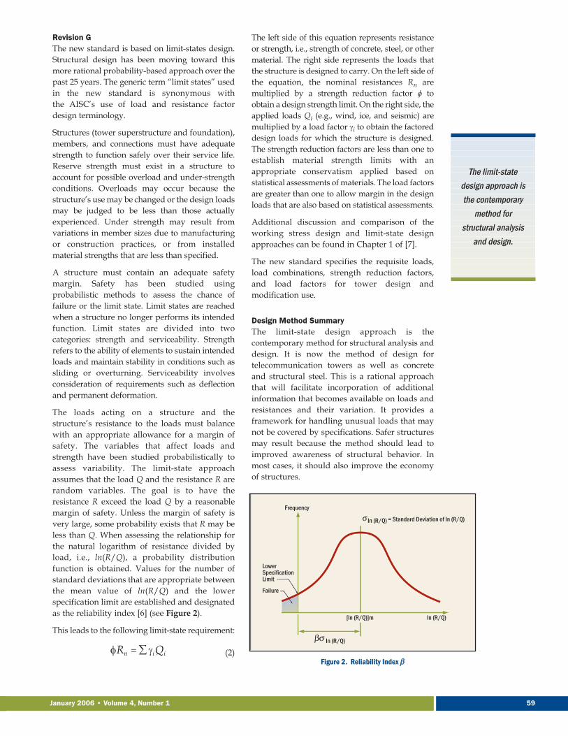
The loads acting on a structure and thestructure’s resistance to the loads must balancewith an appropriate allowance for a margin ofsafety. The variables that affect loads andstrength have been studied probabilistically toassess variability. The limit-state approachassumes that the load Q and the resistance R arerandom variables. The goal is to have theresistance R exceed the load Q by a reasonablemargin of safety. Unless the margin of safety isvery large, some probability exists that R may beless than Q. When assessing the relationship forthe natural logarithm of resistance divided byload, i.e., ln(R/Q), a probability distributionfunction is obtained. Values for the number ofstandard deviations that are appropriate betweenthe mean value of ln(R/Q) and the lowerspecification limit are established and designatedas the reliability index [6] (see Figure 2).
This leads to the following limit-state requirement:
(2)
The left side of this equation represents resistanceor strength, i.e., strength of concrete, steel, or othermaterial. The right side represents the loads thatthe structure is designed to carry. On the left side ofthe equation, the nominal resistances Rn aremultiplied by a strength reduction factor φ toobtain a design strength limit. On the right side, theapplied loads Qi (e.g., wind, ice, and seismic) aremultiplied by a load factor γi to obtain the factoreddesign loads for which the structure is designed.The strength reduction factors are less than one toestablish material strength limits with anappropriate conservatism applied based onstatistical assessments of materials. The load factorsare greater than one to allow margin in the designloads that are also based on statistical assessments.
Additional discussion and comparison of theworking stress design and limit-state designapproaches can be found in Chapter 1 of [7].
The new standard specifies the requisite loads,load combinations, strength reduction factors,and load factors for tower design andmodification use.
Design Method Summary The limit-state design approach is thecontemporary method for structural analysis anddesign. It is now the method of design fortelecommunication towers as well as concreteand structural steel. This is a rational approachthat will facilitate incorporation of additionalinformation that becomes available on loads andresistances and their variation. It provides aframework for handling unusual loads that maynot be covered by specifications. Safer structuresmay result because the method should lead toimproved awareness of structural behavior. Inmost cases, it should also improve the economyof structures.
The limit-statedesign approach isthe contemporary
method forstructural analysis
and design.
January 2006 • Volume 4, Number 1 59
Figure 2. Reliability Index ββ= ∑ γiQiφRn

Bechtel Telecommunications Technical Journal 60
WIND LOADS
Another significant change relates to themigration from fastest-mile wind speed to a
3-second-gust wind speed definition, whichbrings the standard into compliance with othercurrent standards, codes, and guides.
Revision F Section 2.6.1 of the standard defines the basicwind speed as the fastest-mile wind speed at 33 feet above the ground corresponding to anannual probability of 0.02 (50-year recurrenceinterval) for Exposure C. This may be thought ofas the average speed obtained during the passageof 1 mile of wind. For a 70 mph wind, this wouldmean that 1 mile of wind passes in 51.4 seconds.The wind speed is measured by a weather devicecalled an anemometer at a height of 33 feet abovethe ground. The annual probability is based onthe probability distribution function.
As shown in Figure 3, the value of 0.02 indicatesa 2 percent chance that the 70 mph speed will beexceeded in a year or a 98 percent chance that itwill not be exceeded. Wind determinationrequires a probabilistic formulation, and thenecessary probability measures must beestimated on the basis of experimentalformulations. The average time between twoconsecutive annual occurrences of the windexceeding 70 mph is the reciprocal of theprobability of the event within one time unit, i.e.,1/0.02 = 50 years. Therefore, the probability thatthe wind will exceed 70 mph is a 2 percent chancein a given year, and the chance that this speedwill be exceeded in consecutive years occurs onceevery 50 years. The National Oceanic andAtmospheric Administration’s National WeatherService (NWS) branch collects and publisheswind speed data throughout the US.
Revision GIn the new standard, wind speed definition isbased on the 3-second gust. Wind speeds aredeveloped for 3-second gusts at 33 feet aboveground in open-country exposure Category C fora 50-year mean recurrence interval. The NWS hasphased out the measurement of fastest-mile windspeeds, and the basic wind speed has beenredefined as the peak gust, which is recorded andarchived for most NWS stations. The wind speedsare not representative of speeds at which ultimatelimit states are expected to occur. Load factors orallowable stresses used in design equations leadto structural resistances substantially higher thanthe design wind speeds. Figure 4 illustrates awind speed time history record and provides aninterpretation of the two speed definitions.Figures 5 and 6 show lattice towers withsignificant coaxial cable wind load areas.
Figure 4. Wind Speed Record
Figure 3. Largest Annual Fastest-Mile Velocity (V)

January 2006 • Volume 4, Number 1 61
The new standard defines
four methods of structuralanalysis for
seismic loads.
Wind Loads SummaryThe fastest-mile wind speed of 70 mph mentionedpreviously is equivalent to an 85 mph 3-second-gust wind speed. The new standard provides atable of wind speed equivalencies.
This approach to wind loads makes the standardconsistent with ASCE Standard 7 and codes suchas the International Building Code (IBC). It is thecontemporary wind load approach in the US.This standard enables accurate site-specific windmodeling using exposure categories andtopographic effects.
The new standard will use an averaging period of 3 seconds for the US. Other countries usedifferent averaging periods (e.g., 1 hour or 10 minutes). Weather data in the US is collected at465 stations throughout the country.
A description of how to convert the fastest-milewind speed to the 3-second-gust definition can befound in Section 4.0 of Reference [8].
SEISMIC LOADS
Another significant change in the standard isthe inclusion of seismic provisions. This
brings the standard into compliance with othercurrent standards, codes, and guides.
Revision FThe standard does not contain seismic provisions.When seismic loads were considered to apply to aspecific tower design, an equivalent static load,response spectrum modal analysis, or time
history analysis would be applied based on theprovisions contained in applicable buildingcodes.
Revision GThe new standard defines four methods ofstructural analysis for seismic loads. A table isprovided to identify which method is to be usedfor which tower type in accordance with mass andstiffness irregularities. The four approaches are:
• Method 1 – Equivalent Lateral Force
The total weight of the structure, includingappurtenances, is determined; the totalseismic shear is determined and distributedas specified in the standard. The structure isthen analyzed statically using the seismicforces as external loads.
• Method 2 – Equivalent Modal Analysis
The fundamental frequency of the structureis determined along with the seismic forcesfor each level of the structure. The structure isthen analyzed statically using the seismicforces as external loads.
• Method 3 – Modal Analysis
A mathematical model of the structure iscreated that represents the spatialdistribution of the mass and stiffness. Themode shapes—the period, shape factor, andparticipation factor—are determined. Thedesign response spectrum is established inaccordance with the standard. The baseshears and forces at each level of the
Figure 5. Coaxial cable is a major contributor of wind load on a tower. Wind computations are handled
in detail in Revision G.
Figure 6. Towers can be loaded with a very complex array of coaxial cable. Revision G addresses
several load scenarios.

Bechtel Telecommunications Technical Journal 62
structure for each mode are determined andthen combined by the square root of the sumof the squares of the modal values.
• Method 4 – Time History Analysis
A mathematical model of the structure iscreated that represents the spatial distributionof the mass and stiffness consideringstructural damping to be 5 percent of criticaldamping. Two orthogonal ground motiontime histories are selected from recordedevents with seismicity compatible to the site,or synthetic time histories are developed in accordance with accepted practice. A 5 percent horizontal response spectrum isconstructed, and the foregoing time historiesare combined according to rules specified inthe standard to develop two scaled, site-specific time histories. These two timehistories are used to perform a structuralanalysis. Load effects for design aredetermined by selecting the maximum valuesfrom the time history analysis.
Seismic Loads SummaryUnder the new standard, wirelesstelecommunications structures will typically beanalyzed using either Method 1 or 2.
The standard contains provisions for groundmotions, torsional moments, mathematical modelrequirements, and earthquake loads forstructures supported on buildings or othersupporting structures. A seismic approachconsidering the uniqueness of towers will now beincluded and considered as part of the design.
ICE LOADS
The inclusion of ice loading provisionsrepresents a significant change that brings the
standard into compliance with the currentstandards, codes, and guides.
Revision F Though it recognizes a consideration of radial solidice uniform thickness with a density of 56 lb/ft3, the standard does not specifically state an icerequirement. The standard does recognize that ice may be a significant load for structures to belocated in areas of significant ice accumulation andprovides information for consideration in an annex.
Revision G The design ice thickness specified in the newstandard is a uniform radial thickness of glaze ice at 33 feet above the ground in exposure
Category C for a 50-year mean recurrenceinterval. Escalation of ice thickness and wind onice over the height of the structure is required. Ice is assumed to be glaze ice with a density of 56 lb/ft3. Accumulation of ice is considered on thestructure, guys, and appurtenances. All elementsare assumed to be covered with a uniformthickness of ice that results in a wind drag.Design ice thickness is also escalated with heightand is based on regional climatic data. Forengineering design, all members are traditionallyassumed to be covered with a uniform thicknessof ice, which together with the ice density may beused to calculate the ice weight as well as thewind drag.
Ice Loads SummaryThe new standard provides a rational approachfor considering ice thickness in the tower andfoundation design.
EXISTING STRUCTURES
The standard includes provisions for thedesign of existing tower superstructures and
foundations.
Revision F The standard indicates that towers andsupporting structures should be analyzed whenchanges in the original design or operatingconditions take place. Recommended criteriaappear in an annex to the standard.
Revision G A section of the new standard addresses thestructural analysis of existing structures. Anothersection discusses the evaluation of structuresregardless of the standard used in the originaldesign. Existing structures are to be evaluated inthe following circumstances:
• A change in type, size, or number of appurtenances such as antennas,transmission lines, platforms, and ladders
• Any structural modification (except formaintenance) made to the structure
• A change in serviceability requirements
• A change in structure classification inaccordance with the categories identified in the standard
Existing Structures SummaryThe new standard indicates that existingstructures need not be re-evaluated for each
The standardincludes provisions
for the design ofexisting tower
superstructures and foundations.

January 2006 • Volume 4, Number 1 63
The primaryresponsibility of a
registered licensedProfessional
Engineer is theprotection of public,life, safety, health,
welfare, andproperty.
revision of the standard except in thecircumstances listed above. Analyses andmodifications will definitely include modeling,analysis, design, and modification using theprovisions of the standard in computer modelsand calculations.
SOFTWARE
The commercially available software productstypically used for tower analysis, design,
and modification are Power Line Systems, Inc.’s TOWER® and PLS-POLE®, and RISATechnologies’ RISATower. Both companies’software packages are now standard computerapplications in accordance with engineeringdepartment procedures. Both companies areincluding the provisions for the new standard intheir software; this capability will be available inJanuary 2006.
TRAINING
Training in the following subjects is availablefor engineers who work in this area.
Customers may also wish to take advantage ofthis training.
• Telecommunication Tower Overview
The overview training is an orientation for allengineering personnel, regardless ofdiscipline, involved in wireless site projecttower activities. Practical background isprovided to enhance understanding of thedifferent types of towers and foundations,the codes and standards that apply, and thework associated with tower activities.
• ANSI/TIA-222-G-2005 Structural Standardfor Antenna Supporting Structures andAntennas
This offering focuses on the meaning and useof the Revision G standard.
• Telecommunication Tower StructuralAnalysis and Design
This course provides instruction forcivil/structural engineers in the use ofRevisions F and G of the ANSI/TIA-222standard. Training is provided in the use ofthe TOWER, PLS-POLE, and RISATowersoftware packages. Participants model anddesign a lattice steel guyed tower and a self-supporting, tapered tubular steel pole tower.The course provides the backgroundnecessary for an engineer to independentlyanalyze and design telecommunicationtowers. Upon successful completion of the
course and after suitable experience,participants will possess the skill set necessaryto assess, evaluate, analyze, and modifytowers using the ANSI/TIA-222 standard.
LICENSED PROFESSIONAL ENGINEER SEAL
The primary responsibility of a registeredlicensed Professional Engineer is the
protection of public, life, safety, health, welfare,and property. All tower work is to be carried outunder the direction of a licensed ProfessionalEngineer in the Civil and/or Structuresdisciplines in responsible charge as defined instate licensing laws, rules, and regulations. In amajority of states, all companies performingengineering must possess a Certificate ofAuthorization (COA) with an engineer inresponsible charge (ERC) designated on thecertificate. The COA is the state corporate licenseto practice engineering. In states that do notrequire a COA, all companies performingengineering must have an ERC with the appropriate Professional Engineeringregistration.
The drawings, calculations, and reports preparedby civil/structural engineers for owners aremanually wet-stamp sealed or manuallyembossed with a seal and manually signed anddated by a licensed Professional Engineerregistered in the state where the tower structureis located. States are also allowing electronicseals, signatures, and dates on engineeringdeliverables.
CONCLUSIONS
The comprehensive Revision G of Standard 222governing telecommunication tower
activities in the US will continue to guide thecreation of tower structures that successfullyperform their intended function. The standardaddresses both the tower superstructure and the foundation, as both are necessary for thesuccessful performance of a tower in service. The term “tower“ encompasses both thesuperstructure above the ground and thefoundation below the ground functioningtogether to support loads under all designconditions.
The standard has been prepared by individualsand companies who work and practice in thisarea, i.e., fabricators, erectors, consultants,contractors, and architect-engineers. Designs areexpected to be in line with those that result fromapplication of Revision F of the standard.

Bechtel Telecommunications Technical Journal 64
In summary, ANSI/TIA Standard 222 Revision Greflects contemporary engineering practice andincorporates the latest appropriate technicalmethods and academic information. It is awelcomed evolution that brings the science andart of tower design and analysis into conformancewith current provisions of the AISC, ACI, ASCE,IBC, and other national codes, standards, andpractices. �
TRADEMARKS
PLS-POLE and TOWER are registeredtrademarks of Power Line Systems, Inc.
REFERENCES
[1] American National Standards Institute(ANSI)/Telecommunications IndustryAssociation (TIA)/EIA-222-F, Structural Standardsfor Steel Antenna Towers and Antenna SupportingStructures, June 1996.
[2] ANSI/TIA-222-G, Structural Standard for AntennaSupporting Structures and Antennas, August 2005.
[3] Structural Engineering Institute (SEI)/AmericanSociety of Civil Engineers (ASCE) 7-02, MinimumDesign Loads for Buildings and Other Structures,2003.
[4] American Institute of Steel Construction (AISC),Manual of Steel Construction, Load and ResistanceFactor Design.
[5] American Concrete Institute (ACI) 318, BuildingCode Requirements for Structural Concrete.
[6] A.H.-S. Ang and W.H. Tang, Probability Conceptsin Engineering Planning and Design, Volume 1 –Basic Principles, John Wiley & Sons, Inc., 1975.
[7] C.G. Salmon and J.E. Johnson, Steel StructuresDesign and Behavior, Fourth Edition, HarperCollins, 1996.
[8] M.K.S. Madugula, “Dynamic Response of Lattice Towers and Guyed Masts,” ASCE, Reston, Virginia, 2002.
BIOGRAPHYPeter Moskal is chief engineer,civil, structures, and architecture,for Bechtel Telecommunications.He is responsible for the wire-less and wire line infrastructureengineering deliverables, thepeople who prepare thosedeliverables, the processesemployed, and the tools used toexecute the work on behalf of
Bechtel Telecommunications customers. He overseesthe work of civil engineers, structural engineers,architects, and CAD designers and drafters within theTelecommunications organization.
Peter implements defined standard work processes inaccordance with engineering department procedures
and selects and provides the software, design guides,specifications, training, and tools needed to perform the work. He also regularly supports businessdevelopment activities.
Peter is a voting member of ANSI/TIA-222-G-2005standard committee TR-14.7. He holds ProfessionalEngineer licenses in multiple states and serves as thedesignated engineer in responsible charge on a numberof corporate licenses to practice engineering.
Peter received a BS in Civil Engineering and an MS in Civil Engineering (Structures and Soil Mechanics)from the University of Pittsburgh and a BusinessManagement Certificate from Golden Gate University.
Krishnamurthy Raghu is anengineering supervisor inBechtel Telecommunicationscurrently responsible forsupporting Telecommunicationsstaff engineering and self-performance engineering inFrederick, Maryland. Acivil/structural engineer, hehas also worked in Bechtel’s
Power and Petroleum & Chemical business lines. He isexperienced in wireless tower engineering, sitedevelopment, and zoning as well as in the transmissionand distribution industry. He is a technical specialist intower and pole structures and telecommunicationsstandards.
Krishnamurthy is a member of ANSI/TIA-222-G-2005standard committee TR-14.7.
Krishnamurthy received a BE in Civil Engineering fromBangalore University, India, and an MS in CivilEngineering from Virginia Polytechnic Institute andState University (Virginia Tech).