revision to the sudas traffic signal standards – phase...
TRANSCRIPT

Revision to the SUDAS Traffic Signal Standards – Phase 2
Final ReportMay 2012
Sponsored byIowa Highway Research Board(IHRB Project TR-629)Iowa Department of Transportation(InTrans Project 11-394)

About SUDAS
The Iowa Statewide Urban Design and Specifications (SUDAS) Corporation develops and maintains Iowa’s manuals for urban public works improvements, including the SUDAS Design Manual and the SUDAS Standard Specifications.
Disclaimer Notice
The contents of this report reflect the views of the authors, who are responsible for the facts and the accuracy of the information presented herein. The opinions, findings and conclusions expressed in this publication are those of the authors and not necessarily those of the sponsors.
The sponsors assume no liability for the contents or use of the information contained in this document. This report does not constitute a standard, specification, or regulation.
The sponsors do not endorse products or manufacturers. Trademarks or manufacturers’ names appear in this report only because they are considered essential to the objective of the document.
Non-Discrimination Statement
Iowa State University does not discriminate on the basis of race, color, age, religion, national origin, sexual orientation, gender identity, sex, marital status, disability, or status as a U.S. veteran. Inquiries can be directed to the Director of Equal Opportunity and Diversity, (515) 294-7612.
Iowa Department of Transportation Statements
Federal and state laws prohibit employment and/or public accommodation discrimination on the basis of age, color, creed, disability, gender identity, national origin, pregnancy, race, religion, sex, sexual orientation or veteran’s status. If you believe you have been discriminated against, please contact the Iowa Civil Rights Commission at 800-457-4416 or Iowa Department of Transportation’s affirmative action officer. If you need accommodations because of a disability to access the Iowa Department of Transportation’s services, contact the agency’s affirmative action officer at 800-262-0003.
The preparation of this document was financed in part through funds provided by the Iowa Department of Transportation through its “Agreement for the Management of Research Conducted by Iowa State University for the Iowa Department of Transportation” and its amendments.
The opinions, findings, and conclusions expressed in this publication are those of the authors and not necessarily those of the Iowa Department of Transportation.

Technical Report Documentation Page
1. Report No. 2. Government Accession No. 3. Recipient’s Catalog No.
IHRB Project TR-629
4. Title and Subtitle 5. Report Date
Revision to the SUDAS Traffic Signal Standards – Phase 2 May 2012
6. Performing Organization Code
7. Author(s) 8. Performing Organization Report No.
Neal Hawkins, Paul Wiegand, and Beth Richards InTrans Project 11-394
9. Performing Organization Name and Address 10. Work Unit No. (TRAIS)
Institute for Transportation
Iowa State University
2711 South Loop Drive, Suite 4700
Ames, IA 50010-8664
11. Contract or Grant No.
12. Sponsoring Organization Name and Address 13. Type of Report and Period Covered
Iowa Highway Research Board
Iowa Department of Transportation
800 Lincoln Way
Ames, IA 50010
Final Report
14. Sponsoring Agency Code
15. Supplementary Notes
Visit www.intrans.iastate.edu for color pdfs of this and other research reports.
16. Abstract
This report provides a summary of the updates to the traffic signal content within the Iowa Statewide Urban Design and Specifications
(SUDAS) Design Manual Chapter 13 and Standard Specifications Division 8. Major focal points included pole footing design, cabinets
and controllers, monitoring systems, communications systems, and figure updates.
This work was completed through a project task force with a variety of participants (contractors, Iowa Department of Transportation,
city traffic engineers, consultant, vendors, and University research and support staff).
17. Key Words 18. Distribution Statement
fiber optic systems—pole footing design—signal cabinets—signal controllers—
traffic signal communications equipment—traffic signal figures
No restrictions.
19. Security Classification (of this
report)
20. Security Classification (of this
page)
21. No. of Pages 22. Price
Unclassified. Unclassified. 83 NA
Form DOT F 1700.7 (8-72) Reproduction of completed page authorized


REVISIONS TO THE SUDAS TRAFFIC SIGNAL
STANDARDS: PHASE 2
Final Report
May 2012
Principal Investigator
Neal Hawkins, PE
Director, Center for Transportation Research and Education
Institute for Transportation, Iowa State University
Co-Principal Investigator
Paul Wiegand, PE
Director, Statewide Urban Design and Specifications
Institute for Transportation, Iowa State University
Authors
Neal Hawkins, Paul Wiegand, and Beth Richards
Sponsored by
the Iowa Highway Research Board
(IHRB Project TR-629)
Preparation of this report was financed in part
through funds provided by the Iowa Department of Transportation
through its research management agreement with the
Institute for Transportation
(InTrans Project 11-394)
A report from
Institute for Transportation
Iowa State University
2711 South Loop Drive, Suite 4700
Ames, IA 50010-8664
Phone: 515-294-8103
Fax: 515-294-0467
www.intrans.iastate.edu


v
TABLE OF CONTENTS
ACKNOWLEDGMENTS ............................................................................................................ vii
PROJECT BACKGROUND ...........................................................................................................1
PROJECT ACTIVITIES ..................................................................................................................1
SUDAS MANUAL UPDATES .......................................................................................................2
Design Manual .....................................................................................................................2 Specifications Manual ..........................................................................................................3
IMPLEMENTATION ACTIVITIES ...............................................................................................4
FUTURE RESEARCH ....................................................................................................................4
APPENDIX A. SUDAS DEIGN MANUAL CHAPTER 13, SECTIONS 13D-1 (DESIGN
CONSIDERATIONS) AND 13E-1 (SPECIFICATIONS INFORMATION) ................ A-1
APPENDIX B. SUDAS SPECIFICATIONS SECTION 8010 (TRAFFIC SIGNALS) .............B-1
APPENDIX C. MAST ARM POLE FOOTING DESIGN SUMMARY ....................................C-1


vii
ACKNOWLEDGMENTS
The authors would like to thank the Iowa Highway Research Board (IHRB) and Iowa
Department of Transportation (DOT) for sponsoring this research. The authors would also like to
thank the following individuals and groups for their respective involvement.
Committee
Tim Crouch, Iowa DOT
Jennifer Dakovich, City of Des Moines, Iowa
Ron Johnsen, Iowa Signal and Electric
Michael Jorgensen, Iowa DOT
David Ness, City of Dubuque, Iowa
Tom Reis, Iowa DOT
Brian Wilham, Shive-Hattery, Inc.
Subcontractor
The authors wish to thank Snyder & Associates, Inc., especially Tony Boes, Mark Perington, and
Steve Klocke, for their expertise and work in development of the detailed information and the
revised figures.
Industry
Jim Conner, Traffic and Transportation Products Limited (TATPL)
Dan Dillavou, The Waldinger Corporation
Dan Fuchs, Brown Traffic Products, Inc.
Louis Glover, General Traffic Controls, Inc.
Joe Henkels, Baker Electric, Inc.
Doug Ripley, Traffic Control Corporation
Special thanks to Beth Richards for taking the information provided and placing it in the
appropriate format for the Iowa Statewide Urban Design and Specifications (SUDAS) Design
and Specification Manuals.


1
PROJECT BACKGROUND
Iowa Highway Research Board (IHRB) project TR-546 provided an update to the traffic signal
content within the Iowa Statewide Urban Design and Specifications (SUDAS) Design Manual
Chapter 13 and Standard Specifications Division 8. This work was completed through a project
task force with a variety of participants (contractors, Iowa Department of Transportation, city
traffic engineers, consultant, vendors, and University research and support staff).
TR-546 included a major revision to the SUDAS traffic signal specifications. New content was
added and all proprietary references were eliminated. Major revisions to the SUDAS traffic
signal design guidelines were also developed.
Instead of printing various parts of the Manual on Uniform Traffic Control Devices (MUTCD),
the electronic version of the revised design chapter provides hyperlinks to the MUTCD as well
as to other state Department of Transportation (DOT) resources that provide aid to the designer.
The changes developed through TR-546 were implemented in the SUDAS manuals for the 2011
editions.
Due to time and funding constraints for Phase 1 (TR-546), the project task force identified
additional work to complete in Phase 2 (TR-629). This project was approved by the IHRB with
the following work tasks included:
1. Update the existing SUDAS traffic signal figures
2. Conduct a structural review of footing steel and concrete capacities and standards,
and incorporate this information into the SUDAS Design Manual
3. Develop and include non-proprietary, performance-based controller and cabinet
specifications
4. Develop and include non-proprietary fiber optic cable, modem, and communications
specifications
5. Develop and include non-proprietary video monitoring/camera specifications
PROJECT ACTIVITIES
The initial activities included forming an overall project technical advisory committee (TAC)
made up of representatives from the Iowa DOT, the subcontractor on the project (Snyder &
Associates, Inc.), and the Institute for Transportation (InTrans) team. In addition, another
committee was formed that included traffic engineers from cities across the state, a traffic signal
contractor, and consultants who are involved in traffic signal design. A third group of cities,
contractors, and suppliers were also used for input on the draft documents.
A number of opportunities were provided for input from designers, contractors, and suppliers. In
March 2011, the TAC met to establish the study processes and schedule. The existing figures and
specifications were sent to the committee for initial input also in March 2011.

2
Other city traffic engineering professionals in Iowa were also included in the initial input stage,
even though they were not a part of the formal committee:
Jim Dickinson, West Des Moines
Mohammad Elahi, Waterloo
Mark Franz, Council Bluffs
Ron Knoche, Iowa City
Scott Logan, Sioux City
Tom Peterson, Cedar Rapids
Damion Pregitzer, Ames
Gary Statz, Davenport
Using the input received, the InTrans team and Snyder & Associates, Inc. developed the draft
specification changes. The 90 percent draft was developed and presented to the committee for
review in August 2011.
Based on additional input received, modifications were made and the draft changes to the
manuals were sent to the committee for comment on October 10, 2011. On November 29, 2011,
a committee meeting was held at InTrans to make decisions as to what the final draft language
should include.
After changes were made based on the input from the committee, the final draft was sent to the
other engineers listed above and to various contractors and suppliers. In addition, SUDAS staff
initiated the review of the draft at the six SUDAS district committee meetings in February 2012.
Following input received in February, the final changes were made and the documents were
resubmitted during the April SUDAS district committee meetings for final recommendation to
the SUDAS Board of Directors. The SUDAS district committees unanimously recommended
adoption by the SUDAS Board of Directors and the board took action on May 11, 2012 to
approve the revised traffic signal specifications, figures, and design guidance.
SUDAS MANUAL UPDATES
Design Manual
The complete version of the updated sections within SUDAS Design Manual Chapter 13 is
shown in Appendix A. Three general areas within the Design Manual were updated. The first
was one of the most important elements of the research project.
As the SUDAS manuals evolved from the central Iowa area, the parameters used in the design of
the footings for traffic signal poles were lost. To bring some level of certainty to the engineers
using the footing design, a new analysis was conducted using Brohm’s method for lateral
resistance (moment/shear design) per the American Association of State Highway and Traffic

3
Officials (AASHTO) Standard Specifications for Structural Supports for Highway Signs,
Luminaires, and Traffic Signals, 2009 and the Federal Highway Administration (FHWA) Drilled
Shafts: Construction Procedures and LRFD [Load and Resistance Factor Design] Design
Methods (2010) for torsion design. The summary of the analysis process is included in
Appendix C.
The soil strength, wind speed, and gust factor, frost depth, water table depth, and pole loading
parameters were provided. Knowledge of these factors will allow designers to compare their
situations with the parameters used in the SUDAS design.
As a result of this analysis, the depth of the footings and the size of the required reinforcement
increased over the previous SUDAS guidance. One of the committee representatives was
concerned that the calculation may be too conservative and that the footing cost would increase
significantly. Based on that concern, the InTrans team sent out a questionnaire to the cities across
the state to determine what size of footings they were using. All of the respondents matched the
new requirements for depth and steel that were being proposed.
The second area dealt with accessible pedestrian signals. The Americans with Disabilities Act
(ADA) and the MUTCD require the designer to evaluate the need to install accessible pedestrian
signals. The additional guidance provided reminds designers that each evaluation needs to
address the following topics:
Potential demand for pedestrian signals
Requests for accessible signals by persons with visual disabilities
Traffic volumes when pedestrians are present, including low volumes or high right-
turn-on-red volumes
Complexity of the signal phasing, such as split phasing or protected turn phases
Complexity of the intersection geometry
If the accessible pedestrian signal is warranted, the designer is now provided basic information
regarding the ADA requirements.
The third area included updating the new requirements for cabinets and controllers, fiber optic
cables, and cameras used for communications.
Specifications Manual
The completed specifications section is included as Appendix B. The updates included the
following:
Revised all of the figures. Obsolete information was deleted and new information was
included. The appropriate information for contractors was condensed to seven figures,
as opposed to the previous 20 figures.

4
Updated the submittals subsection to allow for electronic submittal of the schedule of
unit prices, the material and equipment list, and shop drawings, if allowed by the
jurisdiction.
Added non-proprietary specifications for fiber optic cable and accessories.
Clarified that reinforcing steel for footings does not need to be epoxy coated.
Added non-proprietary specifications for traffic signal cabinets and controllers
complying with NEMA TS-1 and TS-2 standards. Type 170 equipment is used only
by the City of Des Moines and they agreed to write their own supplemental
specifications to meet their needs.
Added non-proprietary specifications for traffic camera monitoring systems.
Added product information and installation specifications, in addition to a figure, for
a new pedestrian push button post that would be placed to meet ADA accessibility
guidelines when the traffic signal pole placement would cause non-compliance.
IMPLEMENTATION ACTIVITIES
The findings of this research will be shared through incorporation into the SUDAS manuals, as
well as through presentations at a variety of professional, municipal, and national group
presentations. This information will be disseminated and available for use by all agencies that
use the SUDAS manuals.
In addition, discussions will be initiated with the Iowa DOT staff with the intention of making
the specifications and figures joint documents between the Iowa DOT and SUDAS. The joint
documents will not only enhance the overall project timeline for traffic signal construction
activities due to engineer and contractor familiarity, but will also save costs through the use of
consistent equipment and materials.
FUTURE RESEARCH
Due to the relatively recent requirements to evaluate the need for accessible pedestrian signals,
there are no standard specifications available for the required equipment. The next step will be to
develop equipment and installation requirements for the various elements needed for accessible
pedestrian signals.
In addition, further research is anticipated in the area of footing design criteria in contrast to risk
based on experienced failure.

A-1
APPENDIX A. SUDAS DEIGN MANUAL CHAPTER 13, SECTIONS 13D-1 (DESIGN
CONSIDERATIONS) AND 13E-1 (SPECIFICATIONS INFORMATION)


13D-1
Design Manual
Chapter 13 - Traffic Signals
13D - Design Considerations
1 Revised: 2013 Edition
Design Considerations
In addition to basic MUTCD requirements, the safe and efficient operation of a signalized intersection
requires careful attention and balance of a number of design parameters. This section provides some
reference resources for the traffic signal designer in consideration of these features.
A. Geometrics
The geometrics of an intersection are a critical consideration given the potential impact on
intersection safety and performance. Geometrics directly impact sight distance, vehicle separation,
operations, and capacity. As a result, intersection geometrics should always be considered whether
dealing with existing, reconstructed, or new signalized intersections.
References are made to Signalized Intersections: Informational Guide, FHWA-HRT-04-091, August
2004, which provides a single, comprehensive document with methods for evaluating the safety and
operations of signalized intersections and tools to remedy deficiencies. The treatments in this guide
range from low-cost measures such as improvements to signal timing and signage, to high-cost
measures such as intersection reconstruction or grade separation. While some treatments apply only
to higher volume intersections, much of this guide is applicable to signalized intersections of all
volume levels.
1. Basic Geometric Considerations: The geometric design section of the Signalized Intersections:
Informational Guide provides the following comments:
Geometric design of a signalized intersection involves the functional layout of travel lanes, curb
ramps, crosswalks, bike lanes, and transit stops in both the horizontal and vertical dimensions.
Geometric design has a profound influence on roadway safety; it shapes road user expectations
and defines how to proceed through an intersection where many conflicts exist.
In addition to safety, geometric design influences the operational performance for all road users.
Minimizing impedances, eliminating the need for lane changes and merge maneuvers, and
minimizing the required distance to traverse an intersection all help improve the operational
efficiency of an intersection.
The needs of all possible road users must be considered to achieve optimal safety and operational
levels at an intersection. At times, design objectives may conflict between road user groups; the
practitioner must carefully examine the needs of each user, identify the tradeoffs associated with
each element of geometric design, and make decisions with all road user groups in mind.
The Geometric Design section addresses the following design topics to be considered when
designing traffic signal controlled intersections:
3.1 Channelization
3.2 Number of intersection approaches
3.3 Intersection angle
3.4 Horizontal and vertical alignment
3.5 Corner radius and curb ramp design
Chapter 13 - Traffic Signals Section 13D-1 - Design Considerations
2 Revised: 2013 Edition
3.6 Sight distance
3.7 Pedestrian facilities
3.8 Bicycle facilities
2. Additional Sight-distance Considerations:
a. Sight distance is a safety requirement that impacts intersection geometrics as fundamental as
horizontal and vertical alignments. It is a design requirement that is discussed in detail as it
relates to the visibility of traffic signal indications in the MUTCD. In addition to the sight
distance requirements of the MUTCD, the AASHTO “Policy on Geometric Design of
Highways and Streets 2001” states that drivers of the first stopped vehicles on all approaches
should have adequate sight distance to view one another. It also states that left turning
vehicles should have adequate sight distance to select gaps in oncoming traffic and complete
turning maneuvers. This requires consideration of offset left turn lanes to provide adequate
left turn sight distance. If right turns are allowed on a red signal indication, the appropriate
departure sight triangle should be provided. Finally, the policy states that the appropriate
departure sight triangles should be provided for left and right turning vehicles on the minor
approach for two-way flashing operations. Two-way flashing operations are flashing yellow
for the major street and flashing red for the minor street. See Chapter 9 - Intersections in the
AASHTO “Policy on Geometric Design of Highways and Streets 2001” for additional sight
distance information.
b. One sight distance issue that deserves additional consideration is the sight triangle and the
sight obstructions found within it. Certain obstructions are obvious like structures near the
street. Other obstructions are not always obvious or are installed after the traffic signal is
designed and constructed. These obstructions seem to blend into the background. They are
obstructions like entrance monuments, special street name signs, business signs, and
landscape vegetation that may not be a problem initially but become a problem as the plants
reach maturity. Finally, be aware of the signal cabinet size and location including the height
of the footing or cabinet riser so it does not become a sight obstruction.
c. Sight distance requirements are less restrictive at signalized intersections as drivers are
required by law to obey the signal indications; however, there are instances when drivers do
not obey traffic signals. A traffic signal should be designed to exceed minimum sight
distance requirements when possible. Drivers are taught to drive defensively and providing
additional sight distance will only aid drivers in collision avoidance.
3. Turn Lanes:
a. Traffic volumes, turning movement counts, and crash history are used to complete
intersection capacity and accident analyses. The results of the analyses determine the need
for turn lanes, the number of turn lanes, and the length of the turn lanes. The turn lane
information is used to properly design the geometrics of signalized intersection approaches.
b. Turn lane capacity issues often create safety problems. Left or right turning vehicle queues
blocking through traffic create increased potential for rear-end accidents. Sideswipe potential
also increases as traffic attempts to maneuver out of defacto turn lanes or around left turn
queues blocking through lanes. High volumes of turning vehicles combined with high
volumes of opposing vehicles significantly reduce the number and size of available gaps
needed to complete turning maneuvers increasing the potential for right angle collisions. As
a result, properly designed turn lanes improve safety as well as capacity.

Chapter 13 - Traffic Signals Section 13D-1 - Design Considerations
3 Revised: 2013 Edition
c. Determining turn lane design details when upgrading existing signalized intersections in
largely developed areas is relatively straight forward. Capacity problems are recognized
through evidence obtained from capacity analyses, visual inspections, and/or citizen
comments. Capacity analyses and visual inspections of peak hour traffic often reveal long
queues that do not clear after multiple signal cycles. Heavy turning volumes and a lack of
turn lanes on multilane facilities often result in shared lanes acting as defacto turn lanes. If
turn lanes exist, traffic volumes may exceed the capacity of the turn lanes resulting in vehicle
queues spilling out of the turn lanes and into the through lanes.
d. Determining turn lane design details when constructing new signalized intersections in
undeveloped or under developed areas experiencing significant growth is a challenge. In
many cases, there is no visual evidence of existing capacity or safety problems. The
challenge is judging future traffic patterns and the extent of the traffic growth over a given
time period, usually twenty years, with no guarantees as to the type, extent, and rate of
development. Judgment is improved with information and the information is obtained from
capacity analyses that examine existing and proposed development, existing traffic volume
data, and future traffic volume data derived from land use maps and the ITE Trip Generation
Manuals. This information combined with traffic growth rates obtained from developed areas
with similar land use characteristics and engineering judgment are used to arrive at an
intersection design that will support existing traffic volumes as well as future growth.
e. Past experience has helped to formulate several design guidelines used to initially determine
the number of lanes needed at an intersection. These guidelines are planning level guidelines
and should be confirmed with the results of the operational analysis methods discussed in the
Operations section of this chapter. The guidelines can be found in Chapter 10 of the
Highway Capacity Manual 2000 (HCM 2000) and are summarized as follows:
1) Exclusive Left Turn Lanes:
A single exclusive left turn lane should be considered when the minimum left turn
volume is 100 veh/hr.
Dual exclusive left turn lanes should be considered when the minimum left turn
volume is 300 veh/hr.
2) Exclusive Right Turn Lanes:
An exclusive right turn lane should be considered when the right turn volume
exceeds 300 veh/hr and the adjacent mainline volume exceeds 300 veh/hr/ln.
3) Number of Lanes:
Enough lanes should be provided to prevent the total volume of the approach from
exceeding 450 veh/h/ln.
f. Past experience has also helped to formulate several design guidelines used to initially
determine turn lane lengths needed at intersections. Like the guidelines used to determine the
number of lanes, the guidelines used to determine turn lane lengths are planning level
guidelines and should be confirmed with the results of an operational analysis. Also
remember that the lengths discussed here are the actual storage lengths and do not include
taper lengths. Taper requirements are discussed in several sources including the Chapter 5 of
this manual, the Iowa DOT Design Manual, and the AASHTO Policy on Geometric Design
of Highways and Streets. The guidelines are as follows:
Enough storage length should be provided to equal one foot for each vehicle per hour
(vph) turning during the peak hour in the horizon year. For example, 250 vph turning
during the peak hour in the horizon year would require a 250 foot turn lane.

Chapter 13 - Traffic Signals Section 13D-1 - Design Considerations
4 Revised: 2013 Edition
Storage length can also be computed using the following equation:
Storage Length = (h / s) (v + g) (p)
h = horizon year peak hour volume (vph)
s = number of signal cycles per hour
A signal cycle is typically 60 to 120 seconds. Engineering judgment is used to select the
cycle length or lengths to use in the equation.
v = average vehicle length
The average vehicle length often used is 20 feet.
g = average gap between vehicles
The average vehicle gap often used is 5 feet.
p = probability factor
The probability factor is based on the Poisson distribution and associated with the
probability that enough length is provided to store all vehicles.
Probability factor (p) Probability of Storing All Vehicles
1.50 0.90
1.75 0.95
1.85 0.98
2.00 > 0.98
A paper written by the Transportation Research Institute at Oregon State University
suggests modifying the average vehicle length plus gap (v + g) based on the percentage
of trucks using the turn lane. The paper suggests modifying v + g as follows:
Percent trucks v + g
< 2% 25’
5 % 27’
10 % 29’
The initial storage length for dual left turn lanes can be found by dividing the storage
length found from one of the two methods discussed above by 1.8.
Example:
h = 250 vph
s = 100 s/cycle
3600 s/hr / 100 s/cycle = 36 cycles/hr
5% trucks
v + g = 27’
p = 1.85 (95% probability)
Single lane storage length = (250 / 36) (27) (1.75)
Single lane storage length = 328’: Say 325’
Determining turn lane length also requires some additional considerations. One consideration
is the length of the queues in the through lanes. If the turn lanes are not long enough, through
lane queues may prevent turning vehicles from entering the turn lanes leaving the turn lanes

Chapter 13 - Traffic Signals Section 13D-1 - Design Considerations
5 Revised: 2013 Edition
nearly empty until the through lane queues begin clearing. This issue could be addressed
with lagging lefts but lagging lefts require additional considerations to prevent left turn traps
and an operational analysis to determine optimal signal phasing and timing. If through lane
queues block the turn lanes, the turn lanes could be lengthened beyond the through lane
queues. However, the additional length needed may not be practical.
Another consideration is maximum turn lane length. Once a turn lane becomes too long, the
signal cycle cannot serve all the traffic waiting in the turn lane reducing, if not eliminating,
the benefits of the extra length. At this point, it may be more practical to add turn lanes or
look at other solutions to relieve congestion. When is a turn lane too long? It is difficult to
point to an exact number but in the neighborhood of 350 to 400 feet. An operational analysis
will provide better evidence regarding the maximum length.
The final consideration that can impact the length of a turn lane is visibility. A turn lane that
starts just beyond the crest of a vertical curve may not be visible until a vehicle is at the start
of the lane. It may be practical to extend the turn lane to increase its visibility giving drivers
more time to react to the lane.
g. Lane balance should be considered when addressing lane geometrics. Left turn lanes should
be opposing or offset to one another. If dual left turn lanes are required on one approach,
dual left turn lanes or a wide median should be installed on the opposing approach to promote
lane balance. Through lanes should be located so they align with one another as the
intersection is traversed. Creating a lane shift through an intersection creates driver
confusion.
4. Agency Geometric Considerations: The Mn/DOT Traffic Engineering Manual (Section 9-6.00
Traffic Signal Design) provides a good identification of major issues for design consideration and
serves as an example of agency specific criteria. Since this is a PDF document, Sections 9-6.02
through 9-6.05 are provided below:
Intersection geometry is an important element of traffic signal design. The design of traffic signal
system hardware and operation of the traffic signal system should be preceded by a thorough
evaluation and, if necessary, geometric improvement of the existing intersection. Mn/DOT
Section 9-6.03 notes the following geometric elements should be considered:
a. Pavement width should be adequate for anticipated traffic movements and future capacity
requirements. Highway capacity analysis should be performed to get a better understanding
of the capacity of the intersection.
b. If appropriate islands should be designed and constructed so that the driver has adequate
reaction distance to them and they are large enough to install a standard signal foundation.
Existing shoulders should always be carried through the intersection; this will usually provide
enough reaction distance to the island. However, turning radii should be checked to ensure
enough setback for comfortable turns.
c. Turn lanes must provide adequate storage in order to prevent turning traffic from interfering
with other traffic movements and thus causing capacity breakdown.
d. When a median width is more than 30 feet between opposing through lanes, special signal
design considerations are necessary (See MN MUTCD, Section 4H). Extremely wide
medians confuse drivers on the crossing street, prevent them from being comfortable with
opposing traffic, and cause them to lose track of their path. Wide medians also cause
capacity restrictions because more time is needed for vehicle movements and clearances

Chapter 13 - Traffic Signals Section 13D-1 - Design Considerations
6 Revised: 2013 Edition
through the intersection.
e. Sidewalks should be constructed as close to the center of the corner as possible. Pedestrian
crosswalks should be in line with the sidewalk and as close to the intersection as practical.
f. Alignment changes within the intersection should be avoided. Vehicles approaching the
intersection should be directed through the intersection. Vertical alignments approaching
signals must allow for proper signal visibility.
g. Driveways within an intersection should be signalized and accommodated by the intersection
geometrics. Whenever feasible, the driveways should be located or relocated outside the
limits of the intersection.
h. The size of corner radii is an important consideration. Excessively large corner radii may
obscure intersection limits and create a hazard for bicycles and pedestrians, while very small
radii may create a hazard for motorists. Corner radii at signalized intersections should not be
less than 20 feet nor more than 60 feet. A turning radius guide for 58 foot vehicles should be
used to determine proper corner radii. At intersections where bus routes are located, corner
radii should be analyzed giving due consideration to bus maneuvers.
i. It may be necessary to relocate utilities such as manholes, catch basins, fire hydrants,
overhead power and telephone lines and power poles, to obtain adequate geometrics for
signalization. The existence of these utilities must not get in the way of adequate geometrics.
j. Pedestrian curb ramps should be considered in accordance with Chapter 12 if sidewalks are
present.
k. Handhole spacing should be based on the following factors:
Location of junction points within the signal system
Physical features, such as driveways, utilities, etc.
Cable pull length based on size of cable and diameter of conduit
B. Operational Characteristics
The behavior of the traffic at an intersection is another highly important element of signal design.
Mn/DOT Section 9-6.03 notes the following elements should be considered:
1. Existing 15 minute vehicle volumes, by vehicle class, and pedestrian volumes, are the most basic
operational consideration. Data used should represent intersection operation in peak periods.
Saturated approaches should have an upstream count taken to determine the demand volume
rather than the service volume at the intersection.
2. Intersection capacity should be determined based on the Highway Capacity Manual and other
sources.
3. The vehicle approach posted speeds should be determined for the location of advance detection.
4. Adjacent land uses should be evaluated to identify activities which may conflict with intersection
operation. Items that should be considered include entrances, advertising devices, and areas of
high pedestrian activity (schools, manufacturing plants, shopping centers, etc.).
5. Crashes within the intersection should be studied to determine causes and possible design
solutions.

Chapter 13 - Traffic Signals Section 13D-1 - Design Considerations
7 Revised: 2013 Edition
6. Pedestrian volumes and school-crossing activities should be studied to determine pedestrian
routes and necessary design treatments. Pedestrian movements in and around signals should be
routed into the intersection crosswalks in front of vehicles stopped for the signal. Provide
pedestrian refuges in medians 6 feet and wider.
C. System (Arterial) Considerations
In many cases, an individual traffic control signal must be considered as part of a system, either as
one of a series of signals along a linear route, or as one signal in a grid network. Mn/DOT Section 9-
6.04 notes the following elements should be considered.
System considerations in signal design should include but are not limited to the following:
1. Adjacent signals should be interconnected whenever they are less than one-half mile apart, when
the travel time between adjacent signals is less than the cycle length at each signal, or when
platoons leaving one intersection remain intact to the next signal.
2. Properly spaced signalized intersections greatly simplify coordination in planning new signals.
Minimum spacing of one-quarter mile is recommended. Irregular signal spacing reduces the
overall operational efficiency of the mainline movements and greatly complicates signal
coordination.
3. Whenever possible, platoons should be kept intact to allow easier mainline coordination and
minimize cross-street delay.
4. New street or roadway construction should anticipate the need for future signals and the need for
handholes and conduit, particularly under the roadway.
5. Pretimed controllers are used in built-up urban environments, particularly central business
districts. The streets are not excessively wide and the traffic patterns are quite predictable. In
this environment, a signal cycle should contain pedestrian movements. Actuated controllers are
used in suburban and rural environments. In the rural environment, the actuated controller tends
to reduce the number of stops and does not cut off platoons of vehicles. In the suburban
environment, the arterial streets tend to be very wide, and the volumes are usually quite high on
these arterials. There are not usually many pedestrians crossing such an arterial, so an actuated
controller tends to operate much more efficiently, as it is not necessary to time pedestrian
intervals except when an actual demand exists.
6. Splits and offsets should be carefully estimated to determine their impact on arterial flow. A split
is the relative percentage of green time allocated to each of the various phases at a single
intersection. An offset is the travel time between signals, usually expressed in percent of cycle
length.
7. Minimum pedestrian walk and clearance timings should be anticipated when designing
coordinated signal systems.
Chapter 13 - Traffic Signals Section 13D-1 - Design Considerations
8 Revised: 2013 Edition
D. Signal Design Elements
Mn/DOT Section 9-6.05 notes the following elements should be considered:
1. The most efficient operation of a signal system is attained with the fewest phases that are enough
to move traffic without hazardous conflicts. Procedures exist to determine the optimum number
of phases for an intersection.
2. The primary consideration in signal head placement is clear visibility. Drivers approaching an
intersection shall be given a clear and unmistakable indication of their right-of-way assignment.
The number and placement of signal faces shall conform to the requirements of the MUTCD.
Overheads should be located as near as practicable to the line of the driver's normal view. When
an overhead is to control two lanes, it should be installed over the lane line dividing the two lanes.
An overhead should be used over each lane when speeds are above 40 mph. The size of lenses
shall be as stated in the MUTCD. See the signal head placement charts in the Signal Design
Manual. In general, vehicle signal faces should be placed and aimed to have maximum
effectiveness for an approaching driver located a distance from the stop line equal to the distance
traveled while reacting to the signal and bringing the vehicle to a stop at an average approach
speed. Visors, shields, or visual delimiting should be used to help in directing the signal
indication to the approaching traffic, and to reduce sun phantom resulting from external light
entering a signal lens.
3. Vehicle detectors should be placed according to the detector spacing chart and the loop placement
diagrams.
4. At locations where pedestrians are expected, provisions must be made to control pedestrian
activity in and around the signalized intersection. At locations where pedestrians are expected,
pedestrian indications shall be provided if minimum pedestrian crossing time exceeds minimum
vehicular green time, or if any of the conditions set out in section 4E.3 of the MN MUTCD are
met. Pedestrian push buttons should be installed at locations with pedestrian activity where it is
not operationally efficient to provide pedestrian timing on every cycle. Pedestrian signal
indications shall be mounted, positioned, and aimed so as to be in the line of pedestrians' vision,
and to provide maximum visibility at the beginning of the controlled crossing.
5. If it is determined to prohibit pedestrian movement across any approach, that prohibition must be
clearly visible to pedestrians by use of Standard Sign R9-3a on each side of the prohibited
crosswalk. See part 4 of the MN MUTCD for further information.
6. Street lighting should normally be installed with traffic signals and flashing beacons. The
luminaires are generally 250-watt high-pressure sodium vapor luminaires, mounted in the far-
right quadrants of the major street. Larger intersections may require additional luminaires. Forty
foot mounting heights provide even light distribution. Street lights installed on Type A signal
mast-arm poles should be mounted at approximately 350 degrees clockwise from the mast arm in
order to provide frontal illumination of any signs mounted on the mast arm.
Signal design must take into account the existing adjacent lighting systems and the equipment
available to provide access to the luminaires for relamping and maintenance. The presence of
overhead power lines must also be taken into account. These must be designed around or moved.

Chapter 13 - Traffic Signals Section 13D-1 - Design Considerations
9 Revised: 2013 Edition
E. Traffic Signal Operations
The Mn/DOT Traffic Engineering Manual provides an exceptional discussion on basic traffic signal
operations and design considerations. These are not reprinted within this document but these
references are noted below.
Mn/DOT Traffic Signal Timing and Coordination Manual
Traffic Engineering Manual
o Chapter 2. Traffic Signal Phasing and Operations
o Chapter 3. Head Placement Charts
o Chapter 4. Detection
Mn/DOT Signal & Lighting Certification Manual
F. Pedestrian Considerations
1. Geometrics:
a. Geometrics have a significant impact on pedestrian operations and safety at signalized
intersections as alluded to in the previous section. Intersection skew, number of lanes, lane
width, medians, islands, and curb returns all impact the distance pedestrians must travel to
cross an intersection. As the distance to traverse an intersection approach increases, so does
the signal timing that must be allocated to the pedestrian clearance interval. Long pedestrian
clearance intervals have a negative impact on traffic capacity and operations. A pedestrian
actuation will disrupt traffic signal coordination and require several cycles to bring a corridor
back into coordination. However, large pedestrian volumes may dictate signal timing
resulting in less than optimal conditions for vehicles. A traffic engineer must balance the
priorities of vehicles and pedestrians with no calculations or answers that clearly define a
solution but do provide guidance.
b. Right turns present challenges for pedestrians. A driver of a vehicle turning right on red will
be looking left for a gap in traffic. A pedestrian approaching from the right may have a walk
indication. If the driver sees a gap but does not look back to the right, the pedestrian may not
be seen by the driver resulting in a collision. As a result, a traffic engineer must decide
whether to allow right turns on red.
c. Right turn lanes can present additional challenges for pedestrians, especially if the returns are
large and channelize traffic with an island. The islands can channelize right turning vehicles
away from the traffic signal indications creating difficulties signalizing the right turn
movement. Using a stop sign instead of a supplemental signal indication for the channelized
right turning movement is not an option. It creates a confusing message when all movements
on the approach see green indications, including right turning vehicles, until they are partially
through the turning maneuver and see a stop sign. Some agencies assign the right turning
vehicles a yield sign but it creates an issue protecting pedestrians. If a pedestrian push button
is used at the back-of-curb and pedestrians must cross a right turn lane controlled by a yield
sign, it may give pedestrians a false sense of security when crossing in front of right turning
vehicles. Drivers of right turning vehicles see a yield sign and look left, away from the
pedestrians stepping off the curb, for a gap in traffic. In fact, drivers of right turning vehicles
would be looking even farther left due to the channelization and orientation of the vehicles
making it even more difficult for drivers to see pedestrians approaching from the right.
Consequently, pedestrian volume and safety are important considerations when considering
and designing right turn lanes.

Chapter 13 - Traffic Signals Section 13D-1 - Design Considerations
10 Revised: 2013 Edition
d. The final geometric consideration as it relates to pedestrians is the pedestrian refuge. Right
turn islands and medians often double as pedestrian refuges. If islands and medians are
intended to be used as pedestrian refuges, they must be large enough to hold pedestrians and
be ADA compliant. A traffic engineer must consider the likelihood that pedestrians will stop
and get stranded in an island or median. On large approaches, it may be intended that
pedestrians only cross a portion of the approach and stop in a median or island. As a result, a
traffic engineer must decide whether to install supplemental push buttons in the right turn
island or median. If islands and medians are not intended to function as pedestrian refuges,
they must be located so they do not obstruct the path of pedestrians.
2. Visibility: Visibility is important to the safe operation of the pedestrian indications. Pedestrian
indications as well as the push buttons should be easily located by pedestrians. Consider where
vehicles, especially large trucks, may stop so they do not obstruct the view of the pedestrian
indications. This will require careful location of median noses, stop bars, crosswalks, and the
pedestrian heads. Finally, make sure there are no obstructions in the returns that may prevent
drivers and pedestrians from seeing one another such as the signal cabinet or vegetation.
3. Special Considerations: Circumstances often arise that require special considerations. For
example, children may have difficulty understanding the meaning of pedestrian indications.
Count down pedestrian heads may be easier for children to understand; therefore, have increased
value in school zones. Count down pedestrian heads may also have added value on wide
approaches. The flashing numbers can attract a person’s eye and the numbers tell a pedestrian
how much time they have to cross which has added value on very wide approaches. There may
be a particular area within a city that has a high concentration of visually impaired. In this case,
audible pedestrian indications may have added benefit. In many cases, some extra thought and
minimal dollars can change a design from adequate to desirable.
4. Americans with Disabilities Act: The Americans with Disabilities Act (ADA) addresses several
design requirements relating to pedestrians. ADA addresses design requirements for items such
as sidewalk ramps, truncated domes, and pedestrian push buttons. These topics are addressed in
detail in several design manuals such as the MUTCD, the AASHTO Policy on Geometric Design
of Highways and Streets, and Chapter 12 of this manual.
a. Accessible Pedestrian Signals: Each traffic signal project location should be evaluated to
determine the need for accessible pedestrian signals, especially if the project location presents
difficulties for individuals with visual disabilities. An engineering study should be completed
that determines the needs for pedestrians with visual disabilities to safely cross the street.
The study should consider the following factors:
Potential demand for accessible pedestrian signals
Requests for accessible pedestrian signals by individuals with visual disabilities
Traffic volumes when pedestrians are present, including low volumes or high right turn
on red volumes
The complexity of the signal phasing, such as split phasing, protected turn phases,
leading pedestrian intervals, and exclusive pedestrian phases
The complexity of the intersection geometry
If a pedestrian accessible signal is warranted, it is necessary to provide information to the
pedestrian in non-visual formats. This will include audible tones and vibrotactile surfaces.
Pedestrian push buttons should have locator tones for the visually impaired individual to be
able to access the signal. Consistency throughout the pedestrian system is very important.
Contact the Jurisdictional Engineer regarding the standards and equipment types that should
be incorporated into the design of the accessible pedestrian signal system.

Chapter 13 - Traffic Signals Section 13D-1 - Design Considerations
11 Revised: 2013 Edition
b. Location of Pedestrian Push Buttons: It is common to see a narrow grass strip between the
sidewalk and pole used to mount the push buttons or to only see sidewalk on one side of a
pole containing multiple push buttons. It is difficult to impossible for a person in a
wheelchair to reach the push button in cases like these since it often requires the person to
struggle with one wheel in the grass and one on the sidewalk. As a result, sidewalks must be
paved up to the pole used to mount the push buttons and be at a reasonable slope. There
should also be sidewalk on each side of a pole that has a push button. The MUTCD requires
a pedestrian push button mounting height of approximately 3.5 feet above the sidewalk; keep
in mind that the 3.5 feet is above the grade where the pedestrian would be when accessing the
button. Often times pole footing elevations end up above grade and installing a push button
based on the footing elevation and not the ground elevation where the pedestrian accesses the
button results in a mounting height that is too high. Finally, consider the proximity of the
push buttons to the street. If the poles used to mount the push buttons are too far from the
street, pedestrians will not use the push buttons. Consider installing supplemental poles
closer to the street for mounting the push buttons.
G. Driver and Pedestrian Expectations
Other traffic signal design considerations involve driver and pedestrian expectancy. A traffic
engineer must look beyond the traffic signal being designed and consider the characteristics of the
corridor and the attributes of the existing traffic signals along the corridor. For example, left turn
phasing should be applied consistently and not switch between protected only and protected/
permissive without legitimate reasons. If pedestrian signal heads are used, they should be used
consistently and not sporadically where one intersection uses the heads and the next intersection relies
on vehicular signal heads to guide pedestrians. Traffic signal head style, placement, and orientation
should be consistent along a corridor as well as sign type, size, and location. Intersections should not
randomly switch between doghouse and vertical five section heads, center of lane and lane line
placement, or vertical and horizontal signal head orientation. Consistently applied design criteria
improve driver and pedestrian expectations which typically promote safety and operations. However,
circumstances exist that may, at times, require changes to design criteria to increase vehicle and
pedestrian safety and operations.
H. Future Development and Improvements
One of the biggest traffic signal design challenges is designing a traffic signal in an area that is under
developed or being redeveloped. Under these circumstances much of the data needed for design is
either unknown or unstable. Land uses are often modified and business prospects continually change
often having significant impacts on existing and future traffic volumes. In addition, the rate at which
traffic volumes will increase is difficult to determine. In such cases, the traffic signal designer must
work closely with adjacent area land use planning agencies to work towards reasonable expectations
for future travel demands and overall operations. Future phases can be accommodated for within the
design to significantly reduce the need to replace footing locations, adjust mast-arm lengths, or add
additional functionality to the traffic signal. These simple steps can build credibility with the public
and add considerable efficiency to the traffic signal design and overall engineering process.


13E-1
Design Manual
Chapter 13 - Traffic Signals
13E - Specifications Information
1 Revised: 2013 Edition
Specifications Information
This section provides design information that complements and is organized similar to the SUDAS
Specifications Section 8010, which includes:
Part 1 - General
Part 1 provides direction on general items such as submittals; substitutions; delivery, storage, and
handling; scheduling and conflicts; and measurement and payment.
Part 2 - Products
Part 2 describes the products to be provided and is arranged as follows:
2.01 Underground
2.02 Detection
2.03 Communications
2.04 Cabinet and Controller
2.05 Poles, Heads, and Signs
Part 3 - Execution
Part 3 describes how these products should be installed and matches the arrangement described in Part 2,
with the following additions:
3.06 Temporary Traffic Signal
3.07 Surface Restoration
3.08 Testing
3.09 Documentation
The information below provides selective guidance on the specifications.
A. Part 1 - General
1. Submittals: There are several key submittals required of the contractor following award of the
project. These are described below.
a. Schedule of Unit Prices:
1) Document: Prepared by the traffic signal designer and included within the contract
documents (generally attached to the back of the traffic signal specifications).
2) Purpose: Contracting authority approval of the unit pricing for all major traffic signal
items. Establish unit pricing for change order work if needed. Used to estimate partial
payments.
3) Includes: Identification of major traffic signal items along with an estimate of quantity
and units of measurement. Two additional blank columns are provided (unit price, and
unit extension).
4) Contractor Action: Within 30 days after award, the contractor is required to submit a
completed schedule of unit prices to the contracting authority for engineer approval.

Chapter 13 - Traffic Signals Section 13E-1 - Specifications Information
2 Revised: 2013 Edition
5) Engineer Action: Review the schedule in a timely manner. Check the appropriateness
of each unit price, the accuracy of each unit extension calculation, and ensure that the
grand total for all unit extensions matches the lump sum bid item for traffic signalization.
Upon acceptance, sign and date the document and provide a copy to the contractor.
b. Material and Equipment List:
1) Document: Prepared by the traffic signal designer and included within the contract
documents (generally attached to the back of the traffic signal specifications).
2) Purpose: Contracting authority approval of the make and model numbers for all major
traffic signal items.
3) Includes: Identification of major traffic signal items along with an estimate of quantity
and units of measurement. Two additional blank columns are provided (manufacturers
name and each items model number).
4) Contractor Action: Within 30 days after award, the contractor is required to submit a
completed list of materials and equipment to the contracting authority for engineer
approval.
5) Engineer Action: Review the schedule in a timely manner. Check the appropriateness
of each identified manufacturer and model number. Upon acceptance, sign and date the
schedule and provide a copy to the contractor.
c. Contractor Certification:
1) Document: Prepared by the contractor on company letterhead.
2) Purpose: Contracting authority approval of key project personnel.
3) Includes: Name, contact information, and certification of the Level II International
Municipal Signal Association (IMSA) Certified Traffic Signal Technician(s) working on
the project.
4) Contractor Action: Within 30 days after award, the contractor is required to submit the
contractor certification to the contracting authority for engineer approval.
5) Engineer Action: Review the appropriateness of the information and on acceptance,
sign and date the document, and provide a copy to the contractor.
d. Shop Drawings:
1) Document: Prepared by the traffic signal pole supplier for the contractor.
2) Purpose: Contracting authority approval of traffic signal poles, supports, and related
hardware.
3) Includes: Shop drawing information detailing each traffic signal pole, accompanying
parts, and necessary hardware.
4) Contractor Action: Within 30 days after award, submit shop drawings to the
contracting authority for engineer approval.
5) Engineer Action: Review the shop drawings in a timely manner. Check the
appropriateness of each detail. Upon acceptance, sign and date the shop drawings and
provide a copy to the contractor.
e. Catalog Cuts:
1) Document: Prepared by the traffic signal equipment supplier for the contractor.
2) Purpose: Contracting authority approval of all items within the equipment and materials
list as well as for supporting components.
3) Includes: Catalog cut information detailing the make, model number, manufacturer, and
specific details for all traffic signal equipment.
4) Contractor Action: Within 30 days after award, submit catalog cuts to the contracting
authority for engineer approval.

Chapter 13 - Traffic Signals Section 13E-1 - Specifications Information
3 Revised: 2013 Edition
5) Engineer Action: Review the catalog cuts in a timely manner. Check the
appropriateness of each item. Upon acceptance, sign and date the catalog cut documents
and provide a copy to the contractor.
2. Substitutions: Comply with SUDAS Specifications Division 1 - General Provisions and
Covenants.
3. Delivery, Storage, and Handling: Comply with SUDAS Specifications Division 1 - General
Provisions and Covenants.
4. Scheduling and Conflicts: Comply with SUDAS Specifications Division 1 - General Provisions
and Covenants.
5. Special Requirements: Comply with the current edition of the MUTCD as adopted by the Iowa
DOT.
6. Measurement and Payment: Traffic signal work is typically bid as a lump sum item of which
no measurements are made. However, partial payments to the contractor are established through
measuring installed quantities and applying these quantities to the appropriate approved unit price
(see Schedule of Unit Prices above).
B. Part 2 - Products
1. Underground:
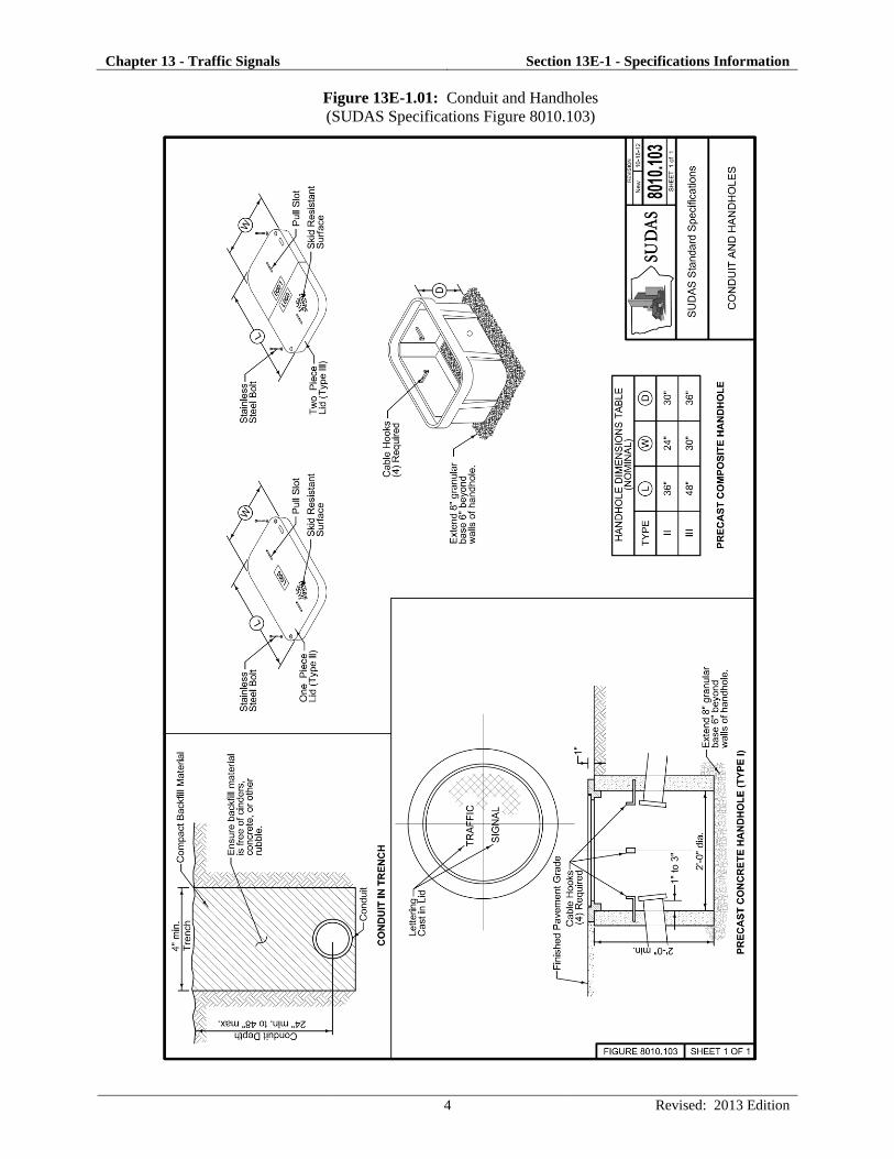
a. Handhole: Handholes are a critical component to traffic signal design. The standard precast
concrete handhole shown in Figure 13E-1.01 is typically used at all locations except where
fiber optic cables are used and adjacent to the controller cabinet.
Composite handholes can come in all shapes and sizes (see Quazite example table) and must
be specified by the Engineer. These are typically made of a polymer concrete. Polymer
concrete is made from selectively-graded aggregates in combination with a polymer resin
system. When combined through a process of mixing, molding and curing, an extremely
powerful cross-linked bond is formed. Precast polymer concrete is reinforced with fiberglass
for strength and rigidity.
The designer should ensure that the contract documents clearly distinguish between handhole
types, sizes, and desired locations. Handholes are typically uniquely numbered on the
contract documents.
An online resource can be found through Chapter 11 Handholes from (Mn/DOT’s 2009
Signal & Lighting Certification Manual) which provides the designer with a photographic
resource for considering handhole features and functions along with execution issues such as
installation, inspection, and key points to remember.
Chapter 13 - Traffic Signals Section 13E-1 - Specifications Information
4 Revised: 2013 Edition
Figure 13E-1.01: Conduit and Handholes
(SUDAS Specifications Figure 8010.103)

Chapter 13 - Traffic Signals Section 13E-1 - Specifications Information
5 Revised: 2013 Edition
b. Conduit: The SUDAS Specifications allow both steel and PVC plastic conduit. Steel
conduit is typically used on all service risers and plastic PVC or HDPE is used at all other
locations. A typical signal installation will use a variety of conduit sizes. When connecting
HDPE conduit to PVC conduit, the designer should work with the Contractor to clarify the
method or materials to be used.
A conduit check list from Mn/DOT Signal Design Documents,Checklists and Worksheets is
noted below: The designer should ensure the following:
Conduit size and cables listed.
Correct symbol for in-place conduit.
Correct symbol for proposed conduit.
Check for conflict with in place underground utilities.
Conduit fill less than 40% (Check).
3 inch RSC minimum size conduit under all public traveled roadways.
Spare 4 inches of conduit out of controller cabinet for future use, threaded and capped.
Conduit runs for interconnect should be as straight as possible.
No PVC above ground (for example: bridge crossings and wood pole systems).
All conduits except those within pads shall drain.
Primary power shall be in a separate conduit run and separate hand holes.
Size of bends and elbows in conduit in accordance with National Electrical Code or UL
guidelines.
If conduit is suspended under a bridge, does the distance between supports conform to
code, is a hanger detail given in plan, and are expansion fittings called for?
Conduit placed under in-place pavement does not need to be labeled (bored or pushed).
An online resource can be found through Chapter 10 Conduits and Fittings (Mn/DOT’s 2009
Signal & Lighting Certification Manual) that provides the designer with a photographic
resource for considering conduit installation and features.
c. Wiring and Cable: Signalized intersections require a variety of standard wires and cables;
however, the number, size, and quantity of extra conductors pulled can vary by agency. The
designer should include sufficient details to ensure the clear identification of cable runs by
conduit. The inspector should make sure all wires are terminated neatly and in an organized
fashion. With the exception of detector lead-in wires, no splices are allowed within
handholes. All plan terminology should be consistent for example:
Cable symbols correct (3/C #12, 2/C #14, 3/C #20 all different, for example).
Ped indications on different phases shall have separate 3/C #12 cables.
Separate 2/C #14 for each detector.
Provide spares for future expansion of system, if necessary, and label them.
An online resource can be found through Chapter 14 Wiring (Mn/DOT’s 2009 Signal &
Lighting Certification Manual) which provides the designer with a photographic resource for
labeling and training wires (very Mn/DOT specific though).
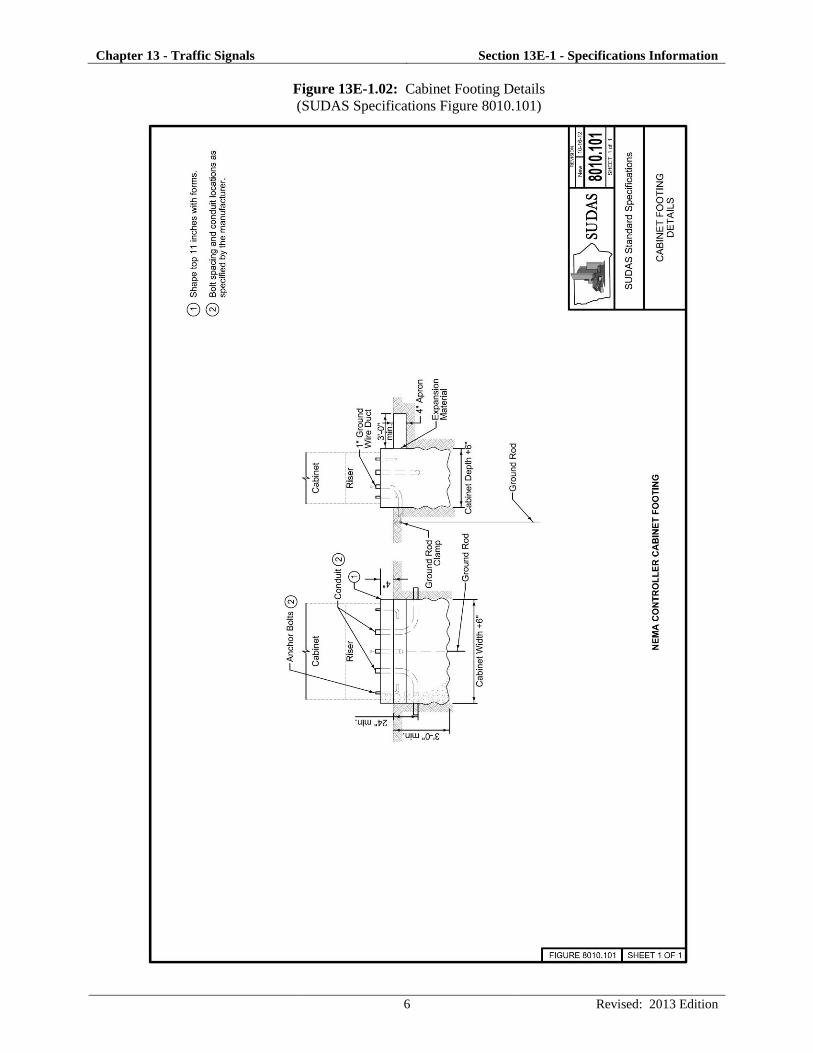
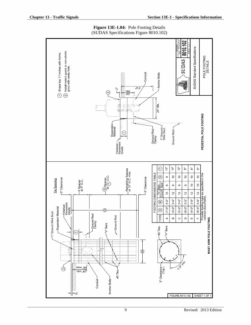
d. Footings: Signalized intersections require footings for all poles, controller pads, and other
service cabinets such as fiber optic hubs or electrical service panels. Controller footing
details are included for NEMA controller cabinets as shown in Figure 13E-1.02. The
designer should ensure that the plans reflect any desired future use spare conduit stubs out of
the footing.
Chapter 13 - Traffic Signals Section 13E-1 - Specifications Information
6 Revised: 2013 Edition
Figure 13E-1.02: Cabinet Footing Details
(SUDAS Specifications Figure 8010.101)

Chapter 13 - Traffic Signals Section 13E-1 - Specifications Information
7 Revised: 2013 Edition
Footing size and depths vary according to pole style, mast-arm length, and pole loadings.
The SUDAS Specifications provide figures for both pedestal poles and for mast-arm poles
(Figure 13E-1.04). SUDAS standard mast arm pole footing designs (Table 13E-1.01 and
Figure 13E-1.04) are based on the following guidelines, parameters, and assumptions:
Brohm’s method for lateral resistance (moment/shear design) per AASHTO Standard
Specifications for Structural Supports for Highway Signs, Luminaires, and Traffic
Signals, 2009, with a safety factor of 2.0.
FHWA Drilled Shafts: Construction Procedures and LRFD Design Methods, May 2010,
alpha method for torsion design with a safety factor of 1.0.
Disturbed soil due to frost: 2.5 feet for moment/shear design, 5.0 feet for torsion design.
Groundwater assumed present for moment/shear and torsion designs.
Pole loadings as shown in Figure 13E-1.03, with poles designed per AASHTO 1994
specifications. Wind load equals 80 miles per hour with a gust factor of 1.3.
Cohesive soils along the length of the footing with an average blow count (N60) greater
than or equal to eight, which equates to an average unconfined compressive strength (Qu)
greater than or equal to 2.0 kips per square foot.
For pole loading conditions greater than shown in Figure 13E-1.03, granular soils, or lower
strength soils, special footing designs will be required. Soil boring testing should be
performed prior to construction to verify soil types and strengths if non-typical soils are
suspected.
Table 13E-1.01: Standard Mast Arm Pole Footing Designs*
Loading Type
(Figure 13E-1.03)
Maximum Mast Arm
Length (feet)
Footing Type
(Figure 13E-1.04)
1 35 A
2 45 B
3 55 C
3 60 D
4 70 E
4 80 F *Maximum loading as per Figure 13E-1.03; for cohesive (non-granular) soils with Qu
> 2.0 ksf
The footing type for each pole should be included in the contract documents so the contractor
will know what is required at the time of bidding.

Chapter 13 - Traffic Signals Section 13E-1 - Specifications Information
8 Revised: 2013 Edition
Figure 13E-1.03: Mast Arm Pole Loadings for Standard Footing Designs
Chapter 13 - Traffic Signals Section 13E-1 - Specifications Information
9 Revised: 2013 Edition
Figure 13E-1.04: Pole Footing Details
(SUDAS Specifications Figure 8010.102)

Chapter 13 - Traffic Signals Section 13E-1 - Specifications Information
10 Revised: 2013 Edition
The designer should ensure that all foundations:
Are located in compliance with applicable clear zone requirements
Do not conflict with pedestrian walkways or ramps
Are at the proper finish grade elevation
An online resource can be found through Chapter 13 Concrete Foundations (Mn/DOT’s 2009
Signal & Lighting Certification Manual), which provides the designer with a photographic
resource for foundation types and installation details.
e. Bonding and Grounding: All traffic signal installations must be bonded and grounded
according to the National Electrical Code.
Bonding is defined in the Code Book as the permanent joining of metallic parts required to be
electrically connected. In a traffic signal, the term is used to describe the electrical and
mechanical connection of conduit, metal poles, cabinets, and service equipment.
Grounding is defined in the Code as a conducting connection, whether intentional or
accidental, between an electrical circuit or equipment and the earth, or to some conductive
body that serves in place of earth.
The designer should ensure that the contract documents include sufficient notation for the
traffic signalized intersection to be properly bonded and grounded. This includes placing
ground rods at each traffic signal pole and at the controller footing as well as through use of
bonding and grounding jumpers within the handholes.
An online resource can be found through Chapter 12 Bonding and Grounding (Mn/DOT’s
2009 Signal & Lighting Certification Manual), which provides the designer with a
photographic resource for bonding and grounding details.
2. Detection: Detectors provide vehicle and pedestrian inputs to the traffic signal controller.
Proper detector installation, operation, and maintenance is critical to the safe and efficient
operation of any signalized intersection. An online resource to learn more about detection styles,
modes, and typical layouts can be found within Chapter 4 Detection (Traffic Engineering
Manual). Since this document is a PDF, some of the information from this source is provided
below.
Detector sizes and locations vary by agency and by location. SUDAS provides a standard
drawing for a typical rectangular detector loop (Figure 13E-1.05).
An online resource can be found through Chapter 15 Detection (Mn/DOT’s 2009 Signal &
Lighting Certification Manual), which provides the designer with a photographic resource for
installation and mounting details.
a. Inductive Loop Vehicle Detector: The most common type of vehicle detection device in
use today is the inductive loop. This is a loop of wire imbedded in the pavement (saw cut in
existing concrete or NMC loop in new concrete) carrying a small electrical current. When a
large mass of ferrous metal passes over the loop, the magnetic field is disturbed and
generates, or induces, a change in resonant frequency in the wire. This change in frequency
is then recognized by the detector amplifier and signals the controller that a vehicle is present.

Chapter 13 - Traffic Signals Section 13E-1 - Specifications Information
11 Revised: 2013 Edition
Figure 13E-1.05: Inductive Loop Vehicle Detectors
(SUDAS Specifications Figure 8010.104)
Chapter 13 - Traffic Signals Section 13E-1 - Specifications Information
12 Revised: 2013 Edition
b. Pedestrian Push Button Detector: There are a number of ways to provide pedestrian
actuation at a signalized intersection. The most common equipment used by far is the
pedestrian pushbutton detector. Pressing the button provides a contact closure that actuates
the call. There are plenty of examples of good and bad pedestrian pushbutton placement;
however, part of the problem is getting the pedestrian to use the button. Specific information
regarding pedestrian detectors can be found in the MUCTD Section 4E.08 Pedestrian
Detection.
An online resource can be found through Chapter 19 Pedestrian Pushbuttons (Mn/DOT’s
2009 Signal & Lighting Certification Manual), which provides the designer with a
photographic resource for style, installation, and mounting details.
c. Video Detection Camera System: Vehicle detection by video cameras is a popular form of
vehicle detection within Iowa. The rapid processing of video images provides the detection
outputs to the controller. The designer should carefully consider the type of equipment
necessary to provide video detection, the maintenance needs of this equipment, and the
specific installation and mounting requirements necessary.
Designers should consider relevant manufacturer recommendations and other online
resources such as the Guidelines for Using Video Detection at Intersections and Interchanges
by Bonneson at Texas Transportation Institute.
d. Microwave Vehicle Detector: Microwave detection is often used within Iowa during
temporary signal control to provide simple, non-intrusive vehicle detection. A variety of
styles and levels of sophistication exist in the market today.
3. Communications: The designer may be required to provide supplemental specifications for
these items given the highly proprietary nature of this equipment and the needs of the contracting
agency. Generic specifications have been provided in the SUDAS Specifications.
4. Cabinet and Controller: The designer may be required to provide supplemental specifications
for the controller, cabinet, and emergency vehicle pre-emption system given the highly
proprietary nature of this equipment. Generic specifications have been provided in the SUDAS
Specifications. New information was added to the specifications regarding uninterruptable power
supply battery back-up system. The designer should carefully consider the cabinet and mounting
requirements of the battery back-up system.
An online resource can be found through Chapter 22 Traffic Signal Cabinets (Mn/DOT’s 2009
Signal & Lighting Certification Manual), which provides the designer with a photographic
resource for style, installation, and mounting details.
5. Poles, Heads, and Signs:
a. Vehicle Traffic Signal Head Assembly: Vehicle signal heads must comply with the
following MUTCD sections:
Section 4D.16 Number and Arrangement of Signal Sections in Vehicular Traffic Control
Signal Faces
Section 4D.17 Visibility, Shielding, and Positioning of Signal Faces
Section 4D.18 Design, Illumination, and Color of Signal Sections

Chapter 13 - Traffic Signals Section 13E-1 - Specifications Information
13 Revised: 2013 Edition
An online resource can be found through Chapter 17 Traffic Signal Heads (Mn/DOT’s 2009
Signal & Lighting Certification Manual), which provides the designer with a photographic
resource for style, installation, and mounting details.
b. Pedestrian Signal Head Assembly: Pedestrian vehicle signal heads must comply with the
following MUTCD sections:
Section 4E.01 Pedestrian Signal Heads
Section 4E.02 Meaning of Pedestrian Signal Head Indications
Section 4E.03 Application of Pedestrian Signal Heads
Section 4E.04 Size, Design, and Illumination of Pedestrian Signal Head Indications
Section 4E.05 Location and Height of Pedestrian Signal Heads
Section 4E.06 Accessible Pedestrian Signals
Section 4E.07 Countdown Pedestrian Signals
c. Traffic Signal Poles and Mast Arms: Signalized intersections require poles and mast arms
to achieve proper traffic signal and pedestrian head placement. Mast arm details and typical
loadings are shown on Figure 13E-1.03; additional mast arm details are shown on Figure
13E-1.06. The designer should ensure that the plan locations comply with all clear zone,
sight restriction, and pedestrian flow criteria. Vertical clearance to overhead utility lines is a
constant issue that designers should take note of during pre-design field activities. Although
the minimum height from the pavement to the bottom of the signal housing is 15 feet, the
designer should consider the street classification and the volume of large trucks in
establishing the signal height above the pavement. However, the top of the signal housing
cannot exceed 25.6 feet above the pavement. If the project being designed has specific
requirements relative to the elevation of the end of the mast arm in relation to the connecting
point on the vertical pole, include those requirements in the special provisions of the contract
documents.
An online resource can be found through Chapter 16 Mast Arm Poles and Pedestals
(Mn/DOT’s 2009 Signal & Lighting Certification Manual), which provides the designer with
a photographic resource for style, installation, and mounting details.
d. Traffic Signal Pedestal Poles: Pedestal poles provide alternate mounting heights for signal
and pedestrian heads and are much easier to locate within a tight right-of-way. Pedestal pole
details and typical head mounting information are shown in Figure13E-1.07.
e. Traffic Signs: The designer must ensure that all signs comply with Iowa DOT standards and
the MUTCD.

Chapter 13 - Traffic Signals Section 13E-1 - Specifications Information
14 Revised: 2013 Edition
Figure 13E-1.06: Mast Arm Pole Details
(SUDAS Specifications Figure 8010.105)
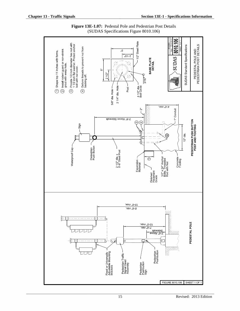
Chapter 13 - Traffic Signals Section 13E-1 - Specifications Information
15 Revised: 2013 Edition
Figure 13E-1.07: Pedestal Pole and Pedestrian Post Details
(SUDAS Specifications Figure 8010.106)

Chapter 13 - Traffic Signals Section 13E-1 - Specifications Information
16 Revised: 2013 Edition
C. Items Requiring Supplemental Specifications
A summary listing of items within SUDAS Specifications Section 8010 requiring supplemental
specifications to be provided by the designer includes the following:
Composite handhole and cover - specify materials and dimensions.
Foundations - specify foundation dimensions and any conduit stubs needed for future use.
Communications - specify all traffic monitoring equipment along with any fiber optic equipment
and materials.
Cabinet, controller, and emergency vehicle preemption - specify all relevant equipment.
Traffic signal poles and mast arms - specify specialty finish for pole if necessary.
Traffic signs - specify sheeting, sign dimensions, and mounting requirements.

B-1
APPENDIX B. SUDAS SPECIFICATIONS SECTION 8010 (TRAFFIC SIGNALS)


SUDAS Standard Specifications Division 8 - Traffic Signals Section 8010 - Traffic Signals
1 10/16/2012
TRAFFIC SIGNALS PART 1 - GENERAL 1.01 SECTION INCLUDES
A. Underground
B. Detection
C. Communications
D. Cabinet and Controller
E. Poles, Heads, and Signs 1.02 DESCRIPTION OF WORK
This part of the specifications includes the furnishing of all material and equipment necessary to complete, in place and operational, traffic control signal(s) as described in the project plans.
1.03 SUBMITTALS
Follow the General Provisions (Requirements) and Covenants as well as the additional requirements listed below. All of the following must be submitted within 30 days after awarding of the contract for the project. Verify the method of submittal with the Jurisdiction. A. Schedule of Unit Prices: Submit a completed schedule of unit prices. Estimates of the
work performed on the project will be made by the Jurisdiction and the unit costs will be used to prepare progress payments to the Contractor.
B. Material and Equipment List: Submit a completed list of materials and equipment to the
Jurisdiction for written approval before any equipment or materials are ordered. C. Contractor Certification: Submit the name(s) and contact information of the International
Municipal Signal Association (IMSA) Level II Certified Traffic Signal Technician(s) working on the project and a copy of their IMSA certificate.
D. Shop Drawings: Submit shop drawings for traffic signal poles and structures to be furnished
on the project. Submit catalog cuts and manufacturer’s specifications for all items in the equipment list.
1.04 SUBSTITUTIONS
Comply with Division 1 - General Provisions and Covenants.
1.05 DELIVERY, STORAGE, AND HANDLING
Comply with Division 1 - General Provisions and Covenants. 1.06 SCHEDULING AND CONFLICTS
Comply with Division 1 - General Provisions and Covenants.

SUDAS Standard Specifications Division 8 - Traffic Signals Section 8010 - Traffic Signals
2 10/16/2012
1.07 SPECIAL REQUIREMENTS
Comply with the current edition of the MUTCD as adopted by the Iowa DOT. 1.08 MEASUREMENT AND PAYMENT
A. Traffic Signal:
1. Measurement: Lump sum item; no measurement will be made. 2. Payment: Payment will be at the lump sum price for traffic signal installation.
B. Temporary Traffic Signal:
1. Measurement: Lump sum item; no measurement will be made. 2. Payment: Payment will be at the lump sum price for temporary traffic signal installation.

SUDAS Standard Specifications Division 8 - Traffic Signals Section 8010 - Traffic Signals
3 10/16/2012
PART 2 - PRODUCTS 2.01 UNDERGROUND
A. Handhole:
1. General: a. Cable Hooks: Provide four galvanized steel cable hooks with a minimum diameter
of 3/8 inch and a minimum length of 5 inches. b. Granular Base: Comply with the following gradations; however, the Engineer may
authorize a change in gradation, subject to materials available locally at the time of construction.
Sieve Percent Passing
2” 100
1 1/2” 80 to 90
1” 15 to 20
3/4” 0 to 0.5
c. Cover: Include “TRAFFIC SIGNAL” as a message on the cover. Alternate
messages may be required as specified in the contract documents. 2. Precast Concrete Handhole:
a. Pipe: Comply with ASTM C 76. Minimum Class III, Wall B (Iowa DOT Class 2000D). Four, 8 inch knockouts (conduit entrance points) equally spaced around the handhole.
b. Casting: Gray cast iron and certified according to requirements of AASHTO M 306 for a 16,000 pound proof-load (HS-20).
3. Composite Handhole and Cover: Composed of mortar consisting of sand, gravel, and
polyester resin reinforced by a woven glass fiber mat or of resin mortar and fiberglass. Ensure the handhole and cover withstands a load of 20,000 pounds. Provide a skid resistant surface on the cover. Provide two 3/8-16 UNC stainless steel hex head bolts with washers.
B. Conduit:
1. General: a. Furnish weatherproof fittings of identical or compatible material to the conduit. Use
standard factory elbows, couplings, and other fittings. b. Use a manufactured conduit sealing compound that is readily workable material at
temperatures as low as 30°F and will not melt or run at temperatures as high as 300°F.
2. Steel Conduit and Fittings:
a. Comply with ANSI C80.1. b. Use weatherproof expansion fittings with galvanized, malleable iron, fixed and
expansion heads jointed by rigid steel conduit sleeves. As an option, the fixed head may be integral with the sleeve, forming a one piece body of galvanized malleable iron.
c. Provide steel bushings.
3. Plastic Conduit and Fittings: a. PVC:
1) PVC Schedule 40 plastic conduit and fittings complying with NEMA TC-2 (pipe), NEMA TC-3 (fittings), and UL 651 for Schedule 40 heavy wall type.

SUDAS Standard Specifications Division 8 - Traffic Signals Section 8010 - Traffic Signals
4 10/16/2012
2.01 UNDERGROUND (Continued) 2) Solvent welded, socket type fittings, except where otherwise specified in the
contract documents. 3) Threaded adaptors for jointing plastic conduit to rigid metal ducts. 4) Provide bell end fittings or bushings.
b. HDPE: 1) Comply with ASTM F 2160 (conduit) and ASTM D 3350 (HDPE material), SDR
13.5. 2) Use orange colored conduit. 3) Continuous reel or straight pieces to minimize splicing. 4) For dissimilar conduit connections, provide an adhesive compatible with both
materials.
C. Wiring and Cable: Provide wire that is plainly marked on the outside of the sheath with the manufacturer's name and identification of the type of the cable.
1. Power Cable: Comply with Iowa DOT Article 4185.12. 2. Signal Cable: Comply with IMSA Specifications 19-1 (PVC jacket) or 20-1 (polyethylene
jacket) for polyethylene insulated, 600 volt, solid, multi-conductor copper wire, #14 American Wire Gauge (AWG).
3. Tracer Wire: Comply with #10 AWG, single conductor, stranded copper, Type
thermoplastic high-heat nylon-coated (THHN), with UL approval, and an orange colored jacket.
4. Communications Cable: Comply with IMSA Specifications 39-2 or 40-2 for #19 AWG,
solid copper conductor, twisted pairs. Use polyethylene insulated, aluminum shielded, complying with REA Specification PE-39 for paired communication cable with electrical shielding.
5. Category 5E (Cat5E) Cable: Provide outdoor use rated cable. 6. Fiber Optic Cable and Accessories:
a. Furnish fiber optic cable of the mode type, size, and number of fibers specified in the contract documents, and all associated accessories.
b. Meet the latest applicable standard specifications by ANSI, Electronics Industries Association (EIA), and Telecommunications Industries Association (TIA).
c. Multimode Fiber:
Core Diameter: 62.5 μm 1.0 μm
Cladding Diameter: 125.0 μm 1.0 μm
Core Concentricity: 1% Max. Attenuation: 3.50 dB/km @ 850 nm
d. Single-Mode Fiber:
Typical Core Diameter: 8.3 μm 1.0 μm
Cladding Diameter: 125.0 μm 1.0 μm
Core Concentricity: 1% Attenuation Uniformity: No point discontinuity greater than 0.1 dB at either 1310 nm or 1550 nm Max. Attenuation: 0.25 dB/km @ 1550 nm, 0.35 dB/km @ 1310 nm
e. Dual layer UV cured acrylate coating applied by the fiber manufacturer, mechanically or chemically strip-able without damage to the fiber.
f. Glass reinforced plastic rod central member designed to prevent the buckling of the cable. Cable core interstices filled with water blocking tape to prevent water infiltration. Dielectric fillers may be included in the cable core where needed to lend symmetry to the cable cross-section.

SUDAS Standard Specifications Division 8 - Traffic Signals Section 8010 - Traffic Signals
5 10/16/2012
2.01 UNDERGROUND (Continued)
g. Buffer tubes of dual layer construction with a polycarbonate inner layer and polyester outer layer. Each buffer tube filled with a water-swellable yarn or tape. Buffer tubes stranded around the central member using reverse oscillation or “SZ” stranding process. Gel-free cable and buffer tubes.
h. Buffer tubes and fibers meeting TIA/EIA-598A, “Color coding of fiber optic cables,” with 12 fibers per buffer tube.
i. Cable tensile strength provided by a high tensile strength aramid yarn and/or fiber glass.
j. All dielectric cables, without armoring, sheathed with medium density polyethylene (1.4 mm minimum nominal jacket thickness). Jacketing material applied directly over the tensile strength members and flooding compound. Jacket or sheath marked in a contrasting color with the manufacturer's name and the words “Optical Cable,” the year of manufacture, and sequential meter or feet marks. Additionally, provide a durable weather proof label on the cable jacket showing the actual attenuation of each fiber expressed in dB/km.
k. Cable fabricated to withstand a maximum pulling tension of 600 pounds during installation (short term) and 135 pounds upon installation (long term).
l. Shipping, storing, and operating temperature range of the cable: -40 C to + 70 C.
Installation temperature range of cable: -10 C to + 60 C. m. Each fiber of all fiber optic cable tested by manufacturer at the 100% level for the
following tests:
Proof tested at a minimum load of 50 kpsi (350 Mpa)
Attenuation n. Meet the appropriate standard Fiber Optic Test Procedure for the following
measurements:
Fluid Penetration
Compound Drip
Compressive Loading Resistance
Cyclic Flexing
Cyclic Impact
Tensile Loading and Bending o. Make cable ends available for testing. Seal cable ends to prevent moisture
impregnation. p. Fiber Distribution Panel: Provide a fiber distribution panel capable of terminating a
minimum of 24 fibers, or as specified in the contract documents. q. Fiber Optic Connectors:
1) ST type connectors of ceramic ferrule and physical contact end finish to terminate multi-mode fibers to equipment.
2) SC type connectors of ceramic ferrule and physical contact end finish to terminate single-mode fibers to equipment.
3) ST or mechanical connectors not allowed for cable splices. 4) Maximum attenuation per connector: 0.75 dB.
r. Fiber Optic Jumpers/Patch Cords: For connections in the cabinet, provide factory-assembled duplex pigtail jumpers with dielectric strength member, durable outer jacket and ST or SC compatible connectors. Provide adequate length for connections and 2 feet minimum slack.
s. Fiber Optic Breakout Kits: Provide breakout kits for separation and protection of individual fibers, with buffering tube and jacketing materials suitable for termination of the fiber and fiber optic connector.
t. Splices/ Splice Enclosures: Fusion splice continuous fiber runs or branch circuit connections in splice enclosures as allowed or specified in the contract documents. Provide environmentally protected outside plant splice enclosures with adequate number of trays to splice all fibers. Maximum attenuation per splice: 0.3 dB.

SUDAS Standard Specifications Division 8 - Traffic Signals Section 8010 - Traffic Signals
6 10/16/2012
2.01 UNDERGROUND (Continued)
D. Footings:
1. Use Class C structural concrete complying with Iowa DOT Section 2403. 2. Use uncoated reinforcing steel complying with Iowa DOT Section 4151.
E. Bonding and Grounding:
1. Ground Rods: Provide 5/8 inch by 8 foot copper clad, steel ground rod at each pole and controller footing.
2. Bonding Jumper or Connecting Wire: Provide #6 AWG bare conductor, copper wire.
2.02 DETECTION
A. Inductive Loop Vehicle Detector: A detector consists of a conductor loop or series of loops installed in the roadway, lead-in (feeder) cable, and a sensor (amplifier) unit with power supply installed in a traffic signal controller cabinet.
1. Cables: All cables must be UL approved.
a. Tube Loop Detector Cable: Comply with IMSA Specifications 51-5. b. Preformed Loop Detector Cable: As approved by the Engineer. c. Loop Detector Lead-in Cable: Comply with IMSA Specifications 50-2.
2. Detector Loop Sealant:
a. Use a rapid cure, high viscosity, liquid epoxy sealant formulated for use in sealing inductive wire loops and leads embedded in pavement. Ensure the cured sealer is unaffected by oils, gasoline, grease, acids, and most alkalis.
b. Use a sealant complying with Iowa DOT Materials I.M. 491.18.
3. Sensor (Amplifier) Unit: a. Use a sensor unit that is solid state, digital, providing detection channel(s) with an
inductance range of 0 to 2,000 micro-henries. Output circuits of the sensor unit will be provided by relays. Vehicle presence will result in a continuous call indication.
b. Provide a sensor unit with the following qualities: 1) Sensitivity adjustment to allow as a minimum the selection of high, medium, or
low sensitivity. 2) Be capable of providing reliable detection of all licensed motor vehicles. 3) Provide an indicator light for visual indication of each vehicle detection. 4) Will not require external equipment for tuning or adjustment. 5) Provide operation in the pulse mode or presence mode. Ensure mode switch is
readily accessible. 6) Provide a self tuning system that is activated automatically with each application
of power. Provide automatic and continuous fine tuning to correct for environmental drift of loop impedance.
7) Provide for fail-safe operation (continuous call) in the event of detector loop failure.
8) Ensure each detector channel will respond to a frequency shift in an increasing or decreasing value as occurs with temperature shifts in the pavement without requiring a locked call.
9) Use detector units with delay and extension timing. The delay feature is selected and adjusted externally on the sensor unit housing. Digitally derived timing is selectable in 1 second increments from 0 to 30 seconds. Ensure delay timing inhibits detector output until presence has been maintained for the time selected. Restart delay timer at each new detection.

SUDAS Standard Specifications Division 8 - Traffic Signals Section 8010 - Traffic Signals
7 10/16/2012
2.02 DETECTION (Continued)
10) Use a sensor unit capable of normal operation without interference and false calls between sensor units ("crosstalk") when installed in the physical environment of the controller cabinet and the electrical environment of the associated electronic equipment installed therein, including other detectors.
B. Pedestrian Push Button Detectors:
1. Assembly: a. Ensure the entire assembly is weather tight, secure against electrical shock,
withstands continuous hard usage. b. Provide a removable contact assembly mounted in a die cast aluminum case. c. Ensure contacts are normally open with no current flowing except at the moment of
actuation. d. Ensure the contacts are entirely insulated from the housing and operating button with
terminals for making connections. e. Provide housing with one outlet for 1/2 inch pipe.
2. Operating Button:
a. Nonrusting metal alloy. b. Ensure the button does not protrude out from the case. c. Supply ADA compliant operating button.
3. Signs: Furnish push button signs complying with MUTCD.
C. Video Detection Camera System: Detects vehicles by processing video images and providing detection outputs to the traffic signal controller.
1. Video Detection System and Processors:
a. Processor to be card rack mounted or located within camera. Compatible with NEMA TS-1, TS-2, and Type 170 controllers and cabinets.
b. Must be capable of the following: 1) Shadow rejection without special hardware. 2) Non-impaired operation under light intensity changes. 3) Maintained operation during various weather conditions (e.g. rain, fog, snow). 4) Anti-vibration, 5% rejection based on image change. 5) Ability to select direction of flow parameters. 6) Ability to properly detect directionally. 7) Operate in presence mode with less than 4% error.
c. Provide user-defined detection zone programming via a graphical user interface (GUI) and any necessary equipment for future programming. Store detection zones in non-volatile memory.
d. Comply with NEMA TS-1 and TS-2environmental and physical standards with an operating temperature of -34°C to +60°C, and 0% to 95% relative humidity.
e. Ensure a factory certified representative from the supplier provides on-site VDS programming and testing.
2. Video Cameras: a. Provide a charge-coupled device (CCD) image sensor with variable focus color or
black and white lens providing a minimum of 4 to at least a 40 degree horizontal field of view.
b. Equipped with internal thermostatically controlled heater and external sunshield. c. Meet NEMA-4 or NEMA-6P environmental standards. d. Use camera cable(s) meeting the manufacturer’s recommendations. Provide a
continuous run, without splices, from the camera to the controller cabinet.

SUDAS Standard Specifications Division 8 - Traffic Signals Section 8010 - Traffic Signals
8 10/16/2012
2.02 DETECTION (Continued)
D. Microwave Vehicle Detectors: Detects all vehicles moving within the field of detection at speeds from 2 to 80 mph.
1. Must be capable of the following:
a. Minimum detection range from 3 to 200 feet for all vehicles. b. Pattern spread of the detection field no more than 16 degrees. c. Self-tuning and capable of continuous operation over a temperature range of -35°F to
165°F. d. Side-fire mount or overhead mount. e. Detecting directional traffic and the direction user selectable.
2. Microprocessor based using Doppler microwave at an operating frequency of 10.525
GHz. 3. FCC certification and tested to the applicable FCC specifications. 4. Enclosure constructed of aluminum or stainless steel and water resistant. 5. All user operated controls and adjustments must be clearly marked and easily accessible. 6. Relay detection output to the controller with a minimum 5 amp rating and designed to
place a constant call to the controller in the event of any failure. 7. Easily accessible indicator showing activation of detection relay. 8. Required wiring as recommended by the manufacturer. 9. Provide mounting hardware for the type of mounting specified in the contract documents
and power supply equipment as recommended by the manufacturer. 2.03 COMMUNICATIONS
A. Traffic Monitoring System: Provide as specified in the contract documents including, video camera in dome, dome mounting bracket and hardware, camera controller, cabling from camera to controller cabinet, and all accessories and hardware necessary for a complete and operational system.
1. Pan/tilt/zoom (PTZ) color camera with automatic conversion to monochrome during low
light levels, auto focus, auto-iris control, electronic image stabilization, privacy masking and high resolution 1/4 inch CCD imager. Minimum optical zoom: 25X. Minimum digital zoom: 12X.
2. Camera system provided in a NEMA 4X or IP66 certified rugged weather-resistant package.
3. Provide all required lightning protection for electronics control, power, and coax video outputs.
4. Operating temperature range: -40ºC to +50ºC.
5. Maximum cable length as specified by camera manufacturer.
6. Provide full 360 degree endless pan and 220 degree tilt under PTZ control.

SUDAS Standard Specifications Division 8 - Traffic Signals Section 8010 - Traffic Signals
9 10/16/2012
2.03 COMMUNICATIONS (Continued)
7. Dome electronics capable of programming a minimum of 64 preset views and nine preprogrammed pattern sequences of preset views. All views selectable by the central office computer or a remote control device.
8. Provide encoder and decoder devices as needed to transmit video over existing or proposed communication systems at 30 frames per second.
9. Provide all necessary rack support devices for video viewing and PTZ control.
10. Provide ability to control PTZ and view video remotely.
B. Fiber Optic Hub Cabinet: As specified in the contract documents. C. Wireless Interconnect Network: Provides two-way data communication between the on-
street master controller and local traffic signal controllers.
1. Data Transceiver: a. Utilize a license-free spread spectrum radio frequency (902-928 MHZ) with frequency
hopping technology. b. Completely programmable by software. Furnish software to the Jurisdiction. c. Built-in diagnostics capabilities. d. Configurable as master, slave, or repeater with store and forward capability. e. Maintains user selectable power output levels between 0.1 and 1 watt. f. Operates with input voltages between 6 VDC and 30 VDC. g. RS-232 interface with 115.2 kbps capability. h. Operating temperature of -40°C to +75°C. i. Receiver sensitivity of -108 to -110 dBm at 10
-6 BER.
j. Protected from power surges. k. Rack or shelf mounted in controller cabinet and connections for antenna, power, and
controller. 2. Antenna:
a. Capable of transmitting and receiving data between intersections. b. Mount near the top of the signal pole nearest the controller cabinet or as specified in
the contract documents. Provide engineer-approved mounting hardware. c. Connect to transceiver via appropriate cable from pole to signal cabinet in same
conduit as traffic signal cable. Conceal cable within a watertight connection at antenna.
2.04 CABINET AND CONTROLLER
A. NEMA Controller, Cabinet, and Auxiliary Equipment: Comply with the latest edition of NEMA TS1 or TS2 standards.
1. Controller:
a. Solid state modular design with digital timing and capable of accommodating at least eight phases.
b. Fully prompted, front panel keyboard with menu driven programmability. c. Local time base scheduler including automatic accommodation for daylight savings
time. d. Local coordination control. e. Local preemption control with at least four programmable internal preemption
sequences. f. Current software and documentation. g. Data retained in a memory medium that does not require battery backup.

SUDAS Standard Specifications Division 8 - Traffic Signals Section 8010 - Traffic Signals
10 10/16/2012
2.04 CABINET AND CONTROLLER (Continued)
2. Cabinet: a. Unpainted aluminum cabinet according to NEMA standards. b. Aluminum cabinet riser with same dimensions as cabinet and 12 to 18 inch height, as
specified in the contract documents. c. Police door with auto/flash switch and on/off power switch for signal heads only.
Controller to remain in full operation regardless of switch positions. d. Maintenance panel on inside of the main door containing the following test switches.
1) Controller power switch. 2) Detector test switches. 3) Stop time switch. 4) Signal flash switch.
e. Heavy-duty clear plastic envelope attached to inside wall of cabinet or cabinet door, for cabinet wiring diagrams, 12 inches by 18 inches minimum.
f. GFI electrical outlet and lamp in accessible location near the front of the cabinet. GFI outlet fused separately from main AC circuit breaker. Fluorescent or LED cabinet lamp connected and fused with GFI outlet.
g. Back panel positions to accommodate phasing and expansibility specified in the contract documents.
h. Power protection devices including AC power circuit breakers, radio interference suppressors, and lightning and surge protectors. 1) AC field service single pole, nonadjustable, magnetic breaker rated for 117 VAC
operation, NEC approved. 2) Radio interference suppressors (RIS) as required to minimize interference in all
broadcast transmission and aircraft frequency bands. 3) Lightning arrestor/surge protector capable of withstanding repeated (minimum of
25) 30,000 ampere surges. i. Neatly train wiring throughout the cabinet and riser. Bundle and attach wiring to
interior panels using nonconductive clamps or tie-wraps.
3. Auxiliary Equipment: Conflict monitor/malfunction management unit, flasher, load switches, terminals and facilities, and miscellaneous equipment and materials according to NEMA standards.
B. Uninterruptible Power Supply Battery Backup System: Monitors 120VAC input from the
electric utility source and automatically switches to/from a system consisting of batteries and electronics.
1. Include a maintenance bypass switch to allow operation of the traffic signal system while
repairs are made to the battery backup system. 2. Designed to provide a minimum of 4 hours of normal operation. 3. Use cabinet equipment that is plug connected and shelf mounted. 4. Designed to cover a temperature range from -30°F to +165°F and include a surge
suppressor. C. Emergency Vehicle Preemption System: As specified in the contract documents.

SUDAS Standard Specifications Division 8 - Traffic Signals Section 8010 - Traffic Signals
11 10/16/2012
2.05 POLES, HEADS, AND SIGNS
A. Vehicle Traffic Signal Head Assembly: Comply with current MUTCD and ITE standards.
1. Housing: a. Individual signal sections made of a durable polycarbonate. Use color specified in
the contract documents. Color to be an integral part of the materials composition. b. Self-contained unit capable of separate mounting or inclusion in a signal face
containing two or more signal sections rigidly and securely fastened together. c. Equipped with openings and positive locking devices in the top and bottom so that it
may be rotated between waterproof supporting brackets capable of being directed and secured at any angle in the horizontal plane.
d. Doors and lenses with suitable watertight gaskets and doors that are suitably hinged and held securely to the body of the housing by simple locking devices of non-corrosive material. Doors are to be easily removed and reinstalled without use of special tools.
2. Optical System: Designed to prevent any objectionable reflection of sun rays even at
times of the day when the sun may shine directly into the lens. 3. Lenses: 12 inch diameter polycarbonate. Do not use glass lenses.
4. Visors:
a. Standard Installation: 1) Each signal lens is to have a visor with the bottom 25% open. 2) Minimum 0.1 inch in thickness and black in color. 3) Fits tightly against the housing door with no filtration of light between the visor
and door. 4) Minimum length of 9 1/2 inches. Ensure the visor angle is slightly downward.
b. Optically Programmed Sections: Make sure the optical unit and visor are designed as a whole to eliminate the return of outside rays entering the unit from above the horizontal.
5. Terminal Block:
a. Three-section signal equipped with a six position terminal block. b. Four- and five-section signal equipped with an eight position terminal block.
6. Backplate:
a. Manufactured one-piece, durable, black plastic capable of withstanding a 100 mph wind.
b. Provides 5 inches of black field around the assembly. 7. Mounting Hardware:
a. Fixed: 1 1/2 inch aluminum pipe and fittings, natural aluminum finish for galvanized poles or match the pole color. Secure to pole with a minimum 5/8 inch wide stainless steel banding material.
b. Universally Adjustable: Rigid mounted, consisting of both top and bottom brackets and easily adjustable in both horizontal and vertical planes.
8. LED Modules: Comply with current ITE standards.

SUDAS Standard Specifications Division 8 - Traffic Signals Section 8010 - Traffic Signals
12 10/16/2012
2.05 POLES, HEADS, AND SIGNS (Continued)
B. Pedestrian Traffic Signal Head Assembly: Comply with current MUTCD and ITE standards.
1. Housing:
a. Made of a durable polycarbonate. Use color specified in the contract documents. Color to be an integral part of the materials composition.
b. Self-contained unit capable of separate mounting or inclusion in a signal face containing one or more signal sections rigidly and securely fastened together.
c. Equipped with openings and positive locking devices in the top and bottom so that it may be rotated between waterproof supporting brackets capable of being directed and secured at any angle in the horizontal plane.
d. Doors and lenses with suitable watertight gaskets and doors that are suitably hinged and held securely to the body of the housing by simple locking devices of non-corrosive material. Doors are to be easily removed and reinstalled without use of special tools.
2. Visor:
a. Tunnel type visor attached to the housing door by stainless steel screws. b. Fit tightly against the housing door to prevent any filtration of light between the door
and the visor. c. Ensure the visor angle is slightly downward.
3. LED Module:
a. Provide a LED unit(s) for the filled upraised hand symbol, walking person symbol, and countdown timer.
b. Ensure immediate blank out of the countdown timer display upon recognizing a shortened “Walk” or a shortened "Flashing Don't Walk" interval.
C. Traffic Signal Poles and Mast Arms:
1. General: a. Mast arm length and vertical pole height as specified in the contract documents. b. Ensure the mast arms, poles, and supporting bases are galvanized inside and out
according to ASTM A 123. c. Continuous tapered, round, steel poles of the transformer base type. Fabricated from
low carbon (maximum carbon 0.30%) steel of U.S. standard gauge. d. When a transformer base is not specified, provide a 6 inch by 16 inch handhole in the
pole shaft for cable access. Provide a cover for the handhole. Secure the cover to the base with simple tools. Hardware to be corrosion resistant.
e. Ensure minimum yield strength of 48,000 psi after manufacture. Supply base and flange plates of structural steel complying with AASHTO M 183 (ASTM A 36) and cast steel complying with ASTM A 27, Grade 65-35 or better.
f. Where a combination street lighting/signal pole is specified in the contract documents, the luminaire arm is to be mounted in the same vertical plane as the signal arm unless otherwise specified. Use a single member tapered type arm for the luminaire arm type. Equip the pole with a minimum 4 inch by 6 inch handhole and cover located opposite the signal mast arm.
g. If allowed by the Engineer, poles and mast arms may be fabricated by welding two sections together, resulting in a smooth joint and factory welded as follows: 1) Ensure a minimum of 60% penetration for plates 3/8 inch and less in thickness
for longitudinal butt welds, except within one foot of a transverse butt-welded joint. Ensure a minimum of 80% penetration for plates over 3/8 inch in thickness.
2) Ensure 100% penetration for longitudinal butt welds on poles and arms within one foot of a transverse butt-welded joint.
3) Ensure 100% penetration, achieved by back-up ring or bar, for transverse butt welds for connecting.

SUDAS Standard Specifications Division 8 - Traffic Signals Section 8010 - Traffic Signals
13 10/16/2012
2.05 POLES, HEADS, AND SIGNS (Continued) 4) Examine 100% of transverse butt welds and 100% penetration longitudinal butt
welds by ultrasonic inspection according to the requirements of AWS D1.1-80.AH.
5) Comply with Structural Welding Code AWS D1-180, as modified by AASHTO 1981 Standard Specifications for Welding of Structural Steel Highway Bridges and by Supplemental Specifications No. 969.
h. Provide non-shrink grout (complying with Iowa DOT Materials I.M. 491.13) or a rodent guard (complying with Iowa DOT Materials I.M. 443.01) for placement between the pole base and the foundation.
2. Pole Design:
a. Comply with AASHTO Standard Specifications for Structural Supports for Highway Signs, Luminaires, and Traffic Signals, 1994.
b. Designed to support the loading necessary for all traffic control equipment. Capable of withstanding winds up to 80 MPH with a 1.3 gust factor without failure.
3. Hardware:
a. Equipped with all necessary hardware and anchor bolts to provide for a complete installation without additional parts.
b. Anchor bolts complying with ASTM F 1554 Grade 105, hot dip galvanized and threaded a minimum of 6 inches at one end and have a 4 inch long, 90 degree bend at the other end.
c. Washers complying with ASTM F 436. d. Heavy hex nuts complying with ASTM A 563. e. All hardware made of steel, hot dipped galvanized complying with ASTM F 2329, or
ASTM B 695, Class 50, Type I, or electrodeposited coated of the same coating thickness and designed for this purpose.
D. Traffic Signal Pedestal Poles:
1. Materials: a. Pedestal: The height from the bottom of the base to the top of the shaft as specified
in the contract documents. b. Pedestal Shaft: Schedule 80 with satin brush or spun finish aluminum tubing. Top
of the shaft outer diameter to be 4 1/2 inches and provided with a pole cap. Supply base collar for poles with shaft lengths greater than 10 feet.
c. Pedestal Base: Cast aluminum, square in shape, with a handhole. 1) Handhole: Minimum of 6 inches by 6 inches and equipped with a cast aluminum
cover that can be securely fastened to the base with the use of simple tools. 2) Base: Minimum weight of 20 pounds with a four bolt pattern uniformly spaced on
a 12 1/2 inch diameter bolt circle. Meet or exceed AASHTO breakaway requirements.
2. Anchor Bolts: Four 3/4 inch by 15 inch steel, hot dip galvanized anchor bolts with right
angle bend at the bottom end, complete with all hardware required for installation.

SUDAS Standard Specifications Division 8 - Traffic Signals Section 8010 - Traffic Signals
14 10/16/2012
2.05 POLES, HEADS, AND SIGNS (Continued)
E. Pedestrian Push Button Post:
1. Material: a. Post: Standard weight (Schedule 40) pipe complying with ASTM F 1083, galvanized
inside and out; 2 1/2 inches in diameter. b. Cap: Waterproof cap complying with ASTM F 626. c. Anchor Bolts: Four 1/2 inch by 24 inch steel, hot dip galvanized anchor bolts
complete with all hardware required for installation. d. Non-shrink Grout: Comply with Iowa DOT Materials I.M. 491.13 or a rodent guard
(complying with Iowa DOT Materials I.M. 443.01) for placement between the post base and the foundation.
e. Base Plate: Provide a 5 inch square, 1/2 inch thick galvanized steel base plate with a 4 1/2 inch bolt circle.
F. Traffic Signs:
1. Comply with Iowa DOT Section 4186.
2. Use a universally adjustable mast arm mounted sign bracket.
3. Comply with MUTCD and the contract documents for the street name sign dimensions, letter height and font, and sheeting.

SUDAS Standard Specifications Division 8 - Traffic Signals Section 8010 - Traffic Signals
15 10/16/2012
PART 3 - EXECUTION 3.01 UNDERGROUND
A. Handhole:
1. Locations:
a. Do not construct in ditch bottoms, low areas where ponding of water may occur, or where they will be subject to normal vehicular traffic.
b. With Engineer approval, additional handholes may be placed, at no additional cost to the Contracting Authority, to facilitate the work.
2. Excavation: Excavate as necessary to accommodate the handhole and granular base. 3. Granular Base: Install 8 inch thick granular base extending a minimum of 6 inches
beyond the outside walls of the handhole. 4. Placement:
a. In paved areas, install the handhole at an elevation so the casting is level and flush with the pavement. In unpaved areas, install the handhole approximately 1 inch above the final grade.
b. Verify ring placement. Invert rings when installed in paved areas.
5. Conduit: a. Remove knockouts as necessary to facilitate conduit entrance. b. Extend conduit into the handhole, through a knockout, approximately 2 inches
beyond the inside wall. Conduit to slope down and away from the handhole. c. Place non-shrink grout (complying with Iowa DOT Materials I.M. 491.13) in the
opening of the knockout area after placement of conduit.
6. Cable Hooks: Install cable hooks centered between the knockouts and the top of the handhole.
7. Backfill: Place suitable backfill material according to Section 3010. 8. Casting: Place the casting on the handhole. Ensure the final elevation meets the
handhole placement requirements.
B. Conduit: 1. General:
a. Place conduit to a minimum depth of 30 inches and a maximum depth of 60 inches below the gutterline. When conduit is placed behind the curb, place to a minimum depth of 24 inches and a maximum depth of 48 inches below top of curb.
b. Change direction at handholes or by bending, such that the conduit will not be damaged or its internal diameter changed. Ensure bends are uniform in curvature and the inside radius of curvature of any bend is no less than six times the internal diameter of the conduit.
c. On the exposed ends of conduit, place bell-end fittings on PVC or HDPE conduit and bushings on steel conduit prior to installing cable. Extend all conduits a minimum of 2 inches and a maximum of 4 inches above the finished surface of any footing or structural base.
SUDAS Standard Specifications Division 8 - Traffic Signals Section 8010 - Traffic Signals
16 10/16/2012
3.01 UNDERGROUND (Continued)
d. When it is necessary to cut and thread steel conduit, do not allow exposed threads. Ensure conduits and fittings are free from burrs and rough places. Clean, swab, and ream conduit runs before cables are installed. Use nipples to eliminate cutting and threading where short lengths of conduit are required. Coat damaged galvanized finish on conduit with zinc rich paint. Use only galvanized steel fittings with steel conduit.
e. Pack conduit ends with a conduit sealing compound.
2. Trenched Installation: a. Place backfill in layers not to exceed 12 inches in depth with each layer thoroughly
compacted before the next layer is placed. Ensure backfill material is free of cinders, broken concrete, or other hard or abrasive materials.
b. Remove all surplus material from the public right-of-way as soon as possible.
3. Trenchless Installation: a. When placing conduit under pavements, use the trenchless installation methods
described in Section 3020. b. If trenchless methods that compact soils in the bore path are used, provide sufficient
cover to prevent heaving of overlying paved surfaces. c. Do not allow pits for boring to be closer than 2 feet to the back of curb, unless
otherwise specified in the contract documents. C. Wiring and Cable:
1. Where practical, follow color codes so that the red insulated conductor connects to the
red indication terminal, yellow to yellow, and green to green. Ensure cables are properly labeled at the controller by durable labels, or other appropriate methods, attached to the cables. Label home runs for cables as follows: northwest corner is red, southeast corner is blue, northeast corner is green, and southwest corner is orange.
2. Install continuous runs of vehicle and pedestrian signal cables from the vehicle or pedestrian signal head to the handhole compartment of the signal pole base. Install continuous runs of vehicle and pedestrian signal cables from the handhole compartment of the signal pole base to the terminal compartment in the controller cabinet. Do not splice signal cables in underground handholes.
3. Install continuous runs for video detection and emergency vehicle preemption cables
from the unit to the controller cabinet.
4. Install continuous runs of power lead-in cables from the service point to the meter socket and from the meter socket to the controller cabinet.
5. Install continuous detector cable from each detector loop to the first handhole adjacent to
the loop. Ensure cables are properly labeled at the controller by durable labels, or other appropriate methods, attached to the cables. Install continuous homerun cable from the splice made in the first handhole to the terminal compartment in the controller cabinet. Attach the drain wire of the shielded cable to the ground in the controller cabinet.
6. Provide a minimum of 4 feet of additional cable at each handhole and loosely coil the extra cable on the handhole cable hooks. Provide a minimum of 2 feet of additional cable at each signal pole (measured from the handhole compartment in the pole to the end of the cable). Provide a minimum of 10 feet of additional cable at each controller base.
7. Pull cables through conduit using a cable grip designed to provide a firm hold upon the exterior covering of the cable or cables, and minimize dragging on the ground or pavement.

SUDAS Standard Specifications Division 8 - Traffic Signals Section 8010 - Traffic Signals
17 10/16/2012
3.01 UNDERGROUND (Continued) 8. Install a tracer wire in all conduits with the exception of conduits between detector loops
and handholes. Use a silicon-filled wire nut to splice the tracer wire in each handhole and at the controller to form a continuous run.
9. Fiber Optic Cable and Accessories:
a. Use a suitable cable feeder guide between the cable reel and the face of the conduit to protect the cable and guide the cable directly into the conduit off the reel. During the installation, carefully inspect cable jacket for defects. If defects are found, notify the Engineer prior to any additional cable being installed. Take care when pulling the cable to ensure the cable does not become kinked, crushed, twisted, snapped, etc.
b. Attach a pulling eye to the cable and use to pull the cable through the conduit. Use a pulling swivel to preclude twisting of the cable. Lubricate cable prior to entering the conduit with a lubricant recommended by the manufacturer. Use dynamometer or break away pulling swing to ensure the pulling tension does not exceed the specified force of 600 pounds or the cable manufacturer's recommendations, whichever is less. Do not allow the cable to twist, stretch, become crushed, or forced around sharp turns that exceed the bend radius or scar or damage the jacket. Manually assist the pulling of the cable at each pull point.
c. Do not pull cable through any intermediate junction box, handhole, pull box, pole base, or any other opening in the conduit unless specified in the contract documents. Install cable by pulling from handhole or controller cabinet to the immediate next downstream handhole or cabinet. Carefully store the remaining length of cable to be installed in the next conduit run(s) in a manner that is not hazardous to pedestrian or vehicular traffic, yet ensures that no damage to the cable occurs. Storage methods are subject to Engineer approval.
d. At each handhole, visibly mark or tag cable, “CITY (or COUNTY) FIBER OPTIC” e. Secure cables inside controller cabinet so that no load is applied to exposed fiber
strands. f. Ensure the radius of the bend for static storage is no less than 10 times the outside
diameter of the cable, or as recommended by the manufacturer. Ensure the radius of the bend during installation is no less than 15 times the outside diameter of the cable, or as recommended by the manufacturer.
g. Provide cable slack in each handhole, junction box, and cabinet as specified in the contract documents. Where handholes or junction boxes lack sufficient area for cable storage or bend radius requirements, provide equivalent additional slack in adjacent facilities. Coil and bind slack cable at three points around the cable perimeter and support in its static storage position.
h. Install fiber optic accessories according to the manufacturer’s recommendations and as specified in the contract documents.
10. Fiber Optic Cable Field Testing: Provide for each fiber both on-reel testing prior to
installation and final testing after installation using a high-resolution optical time domain reflectometer (OTDR). Conduct measurements for single-mode fibers at 1310 ± 30 nanometer wavelength. Conduct measurements for multimode fibers at 850 ±30 nanometer wavelength. Record the identification, location, length, and attenuation measurements of each fiber, and furnish test reports to the Engineer. Replace any cable that fails testing, at no additional cost to the Contracting Authority. a. On-reel Testing: Perform testing for attenuation and continuity using OTDR and a
pigtail splice. Complete testing in one direction only. Acceptable test results will be within ± 3% of factory-supplied attenuation measurements. Except for access to and test preparation of one end of the newly furnished cable, preserve the cable in its originally-shipped condition. Furnish test reports to the Engineer prior to installation.

SUDAS Standard Specifications Division 8 - Traffic Signals Section 8010 - Traffic Signals
18 10/16/2012
3.01 UNDERGROUND (Continued)
b. Cable Segment Testing: Perform an end-to-end attenuation test of each terminated fiber of each fiber optic cable. Perform testing using hand-held optical test sets. Include test results in documentation package provided to the Engineer at the conclusion of the project. Acceptable test results will not exceed the cumulative specified losses of the components. For example, at 850 nanometers, a one kilometer multimode fiber link with two splices and a connector on each end will not exceed 5.6 dB:
1.0 km x 3.5 dB/km: 3.5 dB 0.3 dB per splice x 2: 0.6 dB 0.75 dB per connector x 2: 1.5 dB Maximum allowable loss: 5.6 dB
Repair or replace any cable segment that fails testing. Retest any repaired or replaced cable. Submit complete documentation of test results to the Engineer (hard copy or electronically).
c. Final System Testing: After complete fiber optic system is installed and terminated,
but prior to capping unused fibers, perform OTDR readings on all cables to ensure that each section is in compliance with the specifications. Provide copies of OTDR trace signatures for all fibers for all cable sections to the Engineer. Also provide test results for attenuation test for the installed fibers using the insertion loss procedure and the transmitter/receiver power level test and the continuity test.
D. Footings:
1. Excavation: Excavate to the size, shape, and depth specified in the contract
documents. Ensure the bottom of all foundations rest securely on firm undisturbed soil. Minimize overexcavation to ensure support and stability of the foundation.
2. Footing: Provide a means for holding all of the following elements rigidly in place while
the concrete is being placed. a. Forms:
1) Set the forms level or sloped to meet the adjacent paved areas. 2) When adjacent to paved areas, shape the top 11 inches of the footing to be
square and flush with the surrounding paved area. Provide preformed expansion material between the footing and paved areas.
3) When installed in an unpaved area, set the top of the footing 2 inches above the surface of the ground.
b. Reinforcing Steel: Install reinforcing steel. c. Conduit: Install conduit. d. Anchor Bolts:
1) Set anchor bolts using a template constructed to accommodate the specified elevation, orientation, and spacing according to the pole and controller manufacturer's requirements.
2) Center the pole anchor bolts within the concrete footing. 3) Protect the anchor bolts until poles are erected. 4) Orient controller footing with the back of the cabinet toward the intersection such
that the signal heads can be viewed while facing the controller, unless otherwise directed by the Engineer.
e. Concrete: 1) Place concrete to form a monolithic foundation. Consolidate concrete by
vibration methods. 2) Finish the top of the base level and round the top edges with an edging tool
having a radius of 1/2 inch. Provide a rubbed surface finish on the exposed surface of the footing.

SUDAS Standard Specifications Division 8 - Traffic Signals Section 8010 - Traffic Signals
19 10/16/2012
3.01 UNDERGROUND (Continued)
3) Allow the footings to cure a minimum of 4 days prior to erecting the poles and 7 days prior to installing the mast arms. Times may be shortened if supported by strength test results.
3. Backfill: Place suitable backfill material according to Section 3010.
E. Bonding and Grounding:
1. Ensure the traffic signal installation is grounded as required by the National Electric Safety Code.
2. Install a ground rod at each signal pole and controller footing. 3. Use PVC conduit within the footing to accommodate the connection between the top of
the footing and the ground rod. 4. Bond poles to ground rods with copper wire. Connect ground wires to ground rods with
approved mechanical connectors. 5. Bond rigid steel conduit ends in handholes with copper wire and approved fittings.
3.02 DETECTION
A. Detector Loop Cable Installation:
1. Coordinate the location of the detector loop with the Engineer. Obtain the Engineer’s approval prior to cutting the pavement.
2. Saw to ensure proper depth and alignment of the slot. Make a 2 inch deep clean,
straight, well-defined 3/8 inch wide saw cut without damage to adjacent areas. Overlap the saw cuts where the detector loop changes direction to provide full depth at all corners. Do not use right angle or corners less than 90 degrees.
3. Before installing the detector loop cable, check the saw cuts for the presence of jagged edges or protrusions and remove if present. Clean and dry the saw cuts to remove cutting dust, grit, oil, moisture, or other contaminants. Clean by flushing with a stream of water under pressure. Use oil-free compressed air to dry the saw cuts.
4. Install detector loop cable without damage. Place three turns of the detector loop cable into the saw cut. Seal the ends of the tubing at the time of placement to prevent entrance of moisture.
5. Ensure the detector loop cables are in the bottom of the saw cut. Place detector loop
sealant within the saw cut area. Comply with the manufacturer’s instructions for mixing and using the detector loop sealant.
6. Install preformed loop detector according to the manufacturer’s recommendations. 7. Identify each detector loop cable in the handhole by phase and location. Wind loops that
are physically adjacent in an individual lane or adjacent lanes with opposite rotation (i.e. #1 clockwise, #2 counter-clockwise, #3 clockwise, etc.). Rotation reversal can be accomplished by reversing leads at the handhole.
8. Twist, with at least five turns per foot, all lengths of loop wires and tubing that are not
embedded in the pavement.
SUDAS Standard Specifications Division 8 - Traffic Signals Section 8010 - Traffic Signals
20 10/16/2012
3.02 DETECTION (Continued) 9. Identify all detector loop lead-in cables with appropriate detector numbers. 10. Use a detector loop cable splice kit for the electrical splice between the detector loop
cable and the detector loop lead-in cable to the controller. a. Ensure splice kit provides a watertight protective covering for the spliced wire, the
shielding on the detector loop lead-in cable, and the end of the tubing containing the detector loop cable.
b. Use a manufactured electrical splice kit approved by the Engineer.
11. Test all loops and document by using the following procedures: a. Determine the insulation resistance of the loop wire using a "megger" with 500V
applied to either loop wire to earth ground. The resistance is to be greater than 100 megohms.
b. Determine the inductance of the loop using a loop inductance meter.
B. Pedestrian Push Button Detectors: 1. Install according to the manufacturer’s recommendations. 2. Seal the wire entrance into the pedestrian push button assembly.
C. Video Detection Camera System: Install according to the manufacturer’s recommendations and as specified in the contract documents.
3.03 COMMUNICATIONS
A. Traffic Monitoring System: Install according to the manufacturer’s recommendations and as specified in the contract documents, as well as the following:
1. Position camera dome on the pole as directed by the Engineer.
2. Test installed system under the supervision of the Engineer, and certify as fully-
functional. B. Fiber Optic Hub Cabinet: Install according to the manufacturer’s recommendations and as
specified in the contract documents. 3.04 CABINET AND CONTROLLER
A. Controller, Cabinet, and Auxiliary Equipment:
1. Install according to the manufacturer’s recommendations and as specified in the contract documents.
2. Install on pre-placed caulking material on the concrete base. After the cabinet is installed
in place, place caulking material around the base of the cabinet.
B. Controller: Install according to the manufacturer’s recommendations and as specified in the contract documents.
C. UPS Battery Backup System: Install according to the manufacturer’s recommendations
and as specified in the contract documents. D. Emergency Vehicle Preemption System: Install according to the manufacturer’s
recommendations and as specified in the contract documents.

SUDAS Standard Specifications Division 8 - Traffic Signals Section 8010 - Traffic Signals
21 10/16/2012
3.05 POLES, HEADS, AND SIGNS
A. Vehicle and Pedestrian Traffic Signal Heads:
1. Inspect each signal head assembly while still on the ground for the following: a. Physical defects b. Visor type c. LED wattage d. Lens orientation e. Wiring connections
2. Attach signal head mounting hardware according to the manufacturer’s recommendations. Apply anti-seize compound to all mechanical fasteners.
3. Adjust each signal head both vertically and horizontally to approximate a uniform grade of
all like signal heads.
4. During the course of construction and until the signals are placed in operation, cover signal faces or turn away from approaching traffic. When ready for operation, plumb and aim the heads.
B. Traffic Signal and Pedestal Poles and Pedestrian Push Button Posts:
1. Erect all poles and posts vertically under normal load. 2. Securely bolt the bases to the cast-in-place concrete foundations.
a. Mast Arm Poles: Provide footing type (A through F) as specified in the contract documents. Level by using two nuts on each anchor bolt or according to the manufacturer’s recommendations.
b. Pedestal Poles: Level by using metal shims and one nut on each anchor bolt or according to the manufacturer’s recommendations.
c. Pedestrian Push Button Posts: Weld the post to the base plate using a minimum 3/16 inch weld. Level by using two nuts on each bolt.
3. After leveling the poles, use non-shrink grout or a rodent guard between the pole base
and the foundation. When non-shrink grout is used, neatly finish exposed edges of grout to present a pleasing appearance, and place a weep hole in the grout.
4. Apply anti-seize compound to all mechanical fasteners on pole access doors. 5. Install pedestrian push button post caps with tamper-proof set screws per manufacturer’s
direction or by driving the cap a minimum of 1/2 inch onto the post.
C. Traffic Signs: Install signs using universally adjustable sign brackets banded to the pole. Apply anti-seize compound to all mechanical fasteners.
3.06 TEMPORARY TRAFFIC SIGNAL
Construct according to Figure 8010.107 and to the configuration specified in the contract documents.
3.07 SURFACE RESTORATION
A. Replace or reconstruct features removed as a part of the work, such as sidewalks, driveways, curbs, roadway pavement, unpaved areas, or any other items.
B. Complete restoration according the applicable sections of the SUDAS Standard
Specifications or as directed by the Engineer.

SUDAS Standard Specifications Division 8 - Traffic Signals Section 8010 - Traffic Signals
22 10/16/2012
3.08 TESTING
A. Notify the Engineer 48 hours in advance of the time and date the signal or signal system will be ready for turn on. Do not turn on the signal or signal system without authorization of the Engineer.
B. Ensure a representative from the manufacturer and/or supplier of signal controller or other
authorized person is at the project site when the signal controllers are ready to be turned on to provide technical assistance including, as a minimum, programming of all necessary input data.
C. All required signal timing data will be provided by the Engineer.
D. A test period of 30 calendar days will start upon confirmation from the Engineer that the
signal or signal system is operating consistent with the project requirements. Any failure or malfunction of the equipment furnished by the Contractor, occurring during the test period will be corrected by the Contractor at no additional cost to the Contracting Authority. Upon confirmation by the Engineer that any failure or malfunction has been corrected, a new test period of 30 calendar days will start, exclusive of minor malfunctions such as lamp burnouts. Repeat this procedure until the signal equipment has operated satisfactorily for 30 consecutive calendar days.
E. After signal turn on and prior to completion of the 30 calendar day test period, respond, within 24 hours, to perform maintenance or repair of any failure or malfunction reported.
3.09 DOCUMENTATION
A. Provide file documentation packages with each signal system, consisting of the following:
1. Complete cabinet wiring diagram. 2. Complete physical description of the equipment. 3. Controller printout or equal documentation of initial controller settings installed in the field
or in the office. 4. Product manuals for all cabinet equipment.
5. Standard industry warranties on equipment supplied. 6. Documentation of field cable labeling scheme. 7. Diagram of phasing and detector locations. 8. One set of as-built construction plans indicating changes from the original contract
documents. B. Supply two complete sets of documentation. One set to be placed in the controller cabinet
and the other set (less construction plan) to be delivered to the Engineer.
END OF SECTION

RE
VIS
ION
New
8010
.101
SH
EE
T 1 o
f 1
NE
MA
CO
NT
RO
LL
ER
CA
BIN
ET
FO
OT
ING
DE
TA
ILS
CA
BIN
ET
FO
OT
ING
FIGURE 8010.101 SHEET 1 OF 1
10
-16
-12
4"
Cabin
et
Wid
th +
6"
Mate
rial
Ex
pan
sio
n
Wir
e D
uct
1" G
rou
nd
Cab
inet
Dep
th +
6"
3’-0" min.
4" A
pro
n
1
min
.3’-
0"
24" min.
Ris
er
Ris
er
Cab
inet
Cab
inet
Anchor
Bolt
s
Conduit
Gro
un
d R
od
Gro
un
d R
od
2
2
Cla
mp
Gro
un
d R
od
1
sp
ecif
ied
by
th
e m
an
ufa
ctu
rer.
Bolt
spacin
g a
nd c
onduit
locati
ons a
s
Sh
ap
e t
op
11
in
ch
es w
ith
fo
rms.
2
SU
DA
S S
tandard
Specif
icati
ons


RE
VIS
ION
New
8010
.102
SH
EE
T 1 o
f 1
MA
ST
AR
M P
OL
E F
OO
TIN
G
PE
DE
ST
AL
PO
LE
FO
OT
ING
DE
TA
ILS
PO
LE
FO
OT
ING
FIGURE 8010.102 SHEET 1 OF 1
10
-16
-12
24" min.
2"
"V
" B
ars
"V
" B
ars
FO
OT
ING
DIM
EN
SIO
NS
TA
BL
E
TY
PE
W
D
"V
" B
ars
DW
A B C D E F
Grad
eP
av
em
en
tF
inis
hed
3" C
leara
nce
contr
act
docum
ents
.P
rov
ide f
oo
tin
g t
yp
e a
s s
pecif
ied
in
th
e
3’-0"
min.24"
Wir
e D
uct
1" G
rou
nd
2"
Conduit
Anchor
Bolt
s
Conduit
Anchor
Bolt
s24" d
ia.
Gro
un
d R
od
8"
8"
T
1’-9" min.
#5 T
ies
(Typ.)
3" C
leara
nce
#5 T
ies
3" C
leara
nce
T
Gro
un
d R
od
1" G
round W
ire D
uct
Ex
pan
sio
n M
ate
rial
at
12
" O
.C.
max
.R
em
ain
ing S
paces
Cla
mp
Gro
un
d R
od
1
Grad
eP
av
em
en
tF
inis
hed
Mate
rial
Ex
pan
sio
n
Cla
mp
Gro
un
d R
od
1
11
’-0
"
13
’-0
"
15
’-0
"
16
’-0
"
15
’-0
"
16
’-0
"
3’-
0"
3’-
0"
3’-
0"
3’-
0"
3’-
6"
3’-
6"
CountS
ize
12
12
12
12
12
12
8 8 8 8 10
10
12
"
12
"
12
"
48" max.
at
4" O
.C.
6 S
paces
at
O
.C.
S
paces
S
8"
S 8 10
10
10
10
10
Tie
Spacin
g:
1
gro
ut
wit
h w
eep
ho
le.
Insta
ll r
odent
guard
or
non-s
hri
nk
Sh
ap
e t
op
11
in
ch
es w
ith
fo
rms.
22
2
SU
DA
S S
tandard
Specif
icati
ons

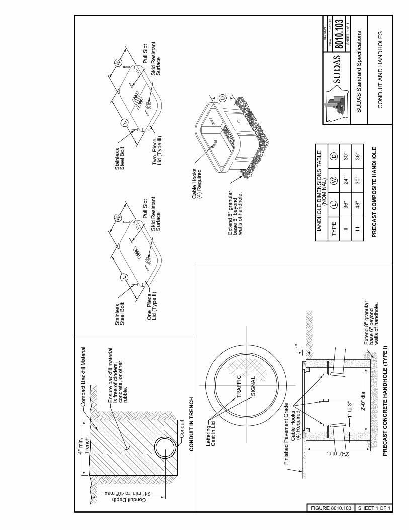
RE
VIS
ION
New
8010
.103
SH
EE
T 1 o
f 1
CO
ND
UIT
IN
TR
EN
CH
CO
ND
UIT
AN
D H
AN
DH
OL
ES
SHEET 1 OF 1FIGURE 8010.103
10
-16
-12
Conduit Depth
Tre
nch
4" m
in.
ru
bb
le.
co
ncre
te,
or
oth
er
is f
ree o
f cin
ders
,E
nsure
backfi
ll m
ate
rial
TR
AF
FIC
SIG
NA
L
2’-0" min.
(4)
Req
uir
ed
Cab
le H
oo
ks
1"
Fin
ish
ed
Pav
em
en
t G
rad
e
1" t
o 3
"
... .. .
.. .. .. .. .....
.. ...
.... .... .. ...
.. . ... . ...
Surf
ace
Sk
id R
esis
tan
t
LOGO
... .. .
.. .. .. .. .....
.. ...
.... .... .. ...
.. . ... . ...
Surf
ace
Sk
id R
esis
tan
t
LOGO
LOGO
TY
PE
II
III
36
"
48
"
24
"
30
"
30
"
36
"
(NO
MIN
AL
)H
AN
DH
OL
E D
IME
NS
ION
S T
AB
LE
Conduit
24" min. to 48" max.
2’-
0" d
ia.
Ste
el
Bolt
Sta
inle
ss
Lid
(T
ype I
l)O
ne P
iece
Ste
el
Bolt
Sta
inle
ss
Lid
(T
yp
e l
ll)
Tw
o P
iece
(4)
Req
uir
ed
Cab
le H
oo
ks
Com
pact
Backfi
ll M
ate
rial
Cast
in L
idL
ett
eri
ng
Pu
ll S
lot
Pu
ll S
lot
PR
EC
AS
T C
OM
PO
SIT
E H
AN
DH
OL
E
wall
s o
f h
an
dh
ole
. base 6
" b
eyond
Exte
nd 8
" g
ranula
r
wall
s o
f h
an
dh
ole
. base 6
" b
eyond
Exte
nd 8
" g
ranula
r
D
L
W
L
W
LW
D
PR
EC
AS
T C
ON
CR
ET
E H
AN
DH
OL
E (
TY
PE
I)
SU
DA
S S
tandard
Specif
icati
ons


RE
VIS
ION
New
8010
.104
SH
EE
T 1 o
f 1
SHEET 1 OF 1FIGURE 8010.104
MO
DIF
IED
DIA
MO
ND
DE
TE
CT
OR
LO
OP
SE
CT
ION
A-A
VE
HIC
LE
DE
TE
CT
OR
S
IND
UC
TIV
E L
OO
P
10
-16
-12
RE
CT
AN
GU
LA
R D
ET
EC
TO
R L
OO
P
A
A
4’-
0"
4’-
0"
2’-
0"
2’-
0"
2’-
0"
Lo
op
Wir
e
2"
3/8
"S
eala
nt
Lo
op
Saw
Cu
t
P
ark
ing
Are
a
Handhole
Lo
op
Saw
Cu
t
Handhole
1" t
o 3
"
1" t
o 3
"
To H
andhole
AA
typ
.
1’-
0"
for
each
lo
op
.D
rill
separa
te h
ole
to h
an
dh
ole
.C
on
tin
uo
us l
oo
p l
ead
s
to h
an
dh
ole
.C
on
tin
uo
us l
oo
p l
ead
s
Pav
em
en
t1
2"
Sh
ou
lder
CU
RB
NO
CU
RB
Pav
em
en
t9"
6’-
0"
in t
he c
ontr
act
docum
ents
Len
gth
(L
) as s
pecif
ied
Flow
Traffic
DE
TE
CT
OR
CO
ND
UIT
EN
TR
Y
Edge o
f P
avem
ent
or
Back o
f C
urb
Conduit
Conduit
SU
DA
S S
tandard
Specif
icati
ons


RE
VIS
ION
New
8010
.105
SH
EE
T 1 o
f 1
SHEET 1 OF 1FIGURE 8010.105
ST
EE
L M
AS
T A
RM
PO
LE
10
-16
-12
PO
LE
DE
TA
ILS
MA
ST
AR
M
Mounting Height
Mast
Arm
Len
gth
as s
pecif
ied i
n t
he c
ontr
act
docum
ents
.
Num
ber
of
sig
nals
, sig
ns, and s
pacin
g
6" t
yp.
Lu
min
air
e A
rm L
en
gth
1 2
co
ntr
ol
an
d s
treet
nam
e s
ign
s.
T
yp
ical
pla
cem
en
t o
f tr
aff
ic
Han
dh
ole
4"X
6"
Min
imu
m
Sid
ew
alk
3’-
6" A
bove
Backpla
tes
Bra
ckets
Adju
sta
ble
Mounti
ng
Fix
ed o
r U
niv
ers
all
y
an
d S
ign
Pu
sh
bu
tto
n
Ped
estr
ian
Lum
inair
e
3
1
32
the c
on
tro
lled
cro
ssw
alk
.
maxim
um
vis
ibil
ity a
t th
e b
egin
nin
g o
f
Po
sit
ion
an
d a
dju
st
head
s t
o p
rov
ide
than 1
0 f
eet
above t
he s
idew
alk
level.
bra
ck
ets
) n
o l
ess t
han
7 f
eet
or
mo
re
bo
tto
m o
f th
e s
ign
al
ho
usin
g (
inclu
din
g
Mount
pedestr
ian s
ignal
heads w
ith t
he
the c
ente
r of
the r
oadw
ay.
sid
ew
alk
, ab
ov
e t
he p
av
em
en
t g
rad
e a
t
the s
idew
alk
or,
if
there
is n
o
8 f
eet
an
d a
max
imu
m o
f 1
9 f
eet
ab
ov
e
locate
d o
ver
a r
oad
way
is a
min
imu
m o
f
(inclu
din
g b
rackets
) th
at
is n
ot
En
su
re t
he b
ott
om
of
the s
ign
al
ho
usin
g
are
at
least
15
feet
ab
ov
e t
he p
av
em
en
t.
sig
nal
housin
g a
nd r
ela
ted a
ttachm
ents
pav
em
en
t.
En
su
re t
he b
ott
om
of
the
no
mo
re t
han
25
.6 f
eet
ab
ov
e t
he
Ensure
the t
op o
f th
e s
ignal
housin
g i
s
SU
DA
S S
tandard
Specif
icati
ons


RE
VIS
ION
New
8010
.106
SH
EE
T 1 o
f 1
SHEET 1 OF 1FIGURE 8010.106
10
-16
-12
PE
DE
ST
AL
PO
LE
Sidewalk
3’-6" Above
12" d
ia.
3/1
6
PO
ST
AN
D F
OO
TIN
G
PE
DE
ST
RIA
N P
US
H B
UT
TO
N
DE
TA
IL
BA
SE
PL
AT
E
PE
DE
ST
RIA
N P
OS
T D
ET
AIL
S
PE
DE
ST
AL
PO
LE
AN
D
1
4’-0" min.
3’-6" Above Sidewalk
2 1
/2"
5"
5"
2 1/2"
1
backin
g o
ff.
Defo
rm t
hre
ads t
o p
revent
nut
from
bolt
wit
h n
ut
cover.
1 1
/2 i
nch
fla
t w
ash
er.
Pro
tect
an
ch
or
Pro
vid
e 1
/2 i
nch d
iam
ete
r hex n
ut
wit
h
gro
ut
wit
h w
eep
ho
le.
Insta
ll r
odent
guard
or
non-s
hri
nk
Sh
ap
e t
op
11
in
ch
es w
ith
fo
rms.
2"
Assem
bly
Sig
nal
Head
Pedestr
ian T
raff
ic
Bra
ckets
Adju
sta
ble
Mounti
ng
Fix
ed o
r U
niv
ers
all
y
Sig
nP
ush
bu
tto
n
Ped
estr
ian
Pushbutt
on
Ped
estr
ian
5’-
6" S
teel
Post
2 1
/2" d
ia.
x
Mate
rial
Ex
pan
sio
n
Grad
eP
av
em
en
tF
inis
hed
Ro
d w
ith
Nu
tB
olt
s,
Th
read
ed
1
/2" x
24
" A
nch
or
Footi
ng
Co
ncre
te1" C
onduit
Wate
rpro
of
Cap
Sig
n
1/2
" S
teel
Pla
te
Post
2 1
/4" d
ia. H
ole
5/8
" d
ia. H
ole
Bolt
Cir
cle
4 1
/2" d
ia.
4
23
2 3 4
8’-0" min.
19’-0" max.
7’-0" min.
10’-0" max.
Pu
sh
Bu
tto
nP
ed
estr
ian
SU
DA
S S
tandard
Specif
icati
ons

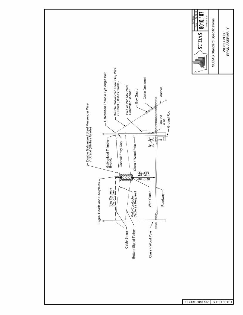
RE
VIS
ION
New
8010
.107
SH
EE
T 1 o
f 1
SHEET 1 OF 1FIGURE 8010.107
10
-16
-12
Anchor
Co
nd
uit
En
try
Cap
Ro
ad
way
Cab
le S
trap
s
Wir
e C
lam
p
15’-0" min.
5%
of
Sp
an
Sag D
ista
nce
6’ min.
Sig
nal
Heads a
nd B
ackpla
tes
MUTCDmax. per
Wir
eG
round
Gro
un
d R
od
7 S
trand (
Uti
liti
es G
rade)
Do
ub
le G
alv
an
ized
Ste
el
Messen
ger
Wir
e
Galv
an
ized
Th
imb
le E
ye A
ng
le B
olt
7 S
trand (
Uti
liti
es G
rade)
Double
Galv
aniz
ed S
teel
Guy W
ire
Cable
Deadend
Cla
ss 4
Wood P
ole
Bo
tto
m S
ign
al
Teth
er
Cla
ss 4
Wo
od
Po
leC
ab
le a
s R
eq
uir
ed
Mu
lti-
Co
nd
ucto
r
Eye N
ut
Galv
an
ized
Th
imb
le
Co
ntr
oll
er
Cab
inet
Po
le o
r P
ad
Mo
un
ted
Gu
y G
uard
5’-0"to
3’-0"
SP
AN
AS
SE
MB
LY
WO
OD
PO
ST
SU
DA
S S
tandard
Specif
icati
ons


C-1
APPENDIX C. MAST ARM POLE FOOTING DESIGN SUMMARY


2409 Grand Avenue
Des Moines, Iowa 50312-5309 515-243-4477 FAX: 515-243-4479 E-Mail: [email protected]
SUDAS Mast Arm Pole Footing Summary SWA 05/08/2012
Pole loadings and anchor bolt layouts were received from both Millerbernd Manufacturing and Valmont Industries for the different mast arm standards. These loads are based on AASHTO Standard Specifications for Structural Supports For Highway Signs, Luminaries, and Traffic Signals, 1994 with a 80 mph wind and a gust factor of 1.3. The controlling loads were used to analyze the footings.
The soil properties controlled the size and depth of the pole footing, as the concrete footing
itself had sufficient capacity, when using adequate reinforcing, for the loadings. The soil properties assumed were:
- Poor cohesive soil with an average blow count (N60) equal to or greater than 8. This blow count equates to a compressive strength of Qu = 2000 psf and c = 1000 psf. These soil properties match the properties used in the standards from the state of Illinois.
- Groundwater is present. - For the moment/shear analysis, 2.5’ of disturbed soil due to frost was assumed based on
engineering judgment. For the torsion analysis, 5’ of disturbed soil was assumed based on the current AASHTO Bridge Design Manual.
- Granular soils were originally designed but they were determined to be a special design case based on the larger depths required.
Two different modes of soil failure were analyzed. The footings were not only checked for
lateral loading from the moment and shear on the mast arms but also for torsion loading from the arm. The moment and shear creates overturning of the footing, while the torsion creates twisting of the footing.
For the moment/shear analysis, guidelines set forth in AASHTO Standard Specifications for
Structural Supports for Highway Signs, Luminaries, and Traffic Signals, 2009 were followed. The Brohm’s Method with a safety factor of 2.0 (per discussions with SUDAS) was used to determine the embedment depth required.
For the torsion analysis, guidelines set forth in FHWA-NHI-10-016 Drilled Shafts: Construction
Procedures and LRFD Design Methods, May 2010 were followed. The alpha method with a safety factor of 1.0 (matches Florida DOT) was used to determine the embedment depth required.
The larger embedment depth from the two failure modes was used to size the mast arm footing.
Reinforcing and ties were then designed based off the footing size.