rf deflecting mode cavities - cern · ω ωω = = ⊥ ic v || v ⊥ ω r for dipole modes, m=1, so...
TRANSCRIPT

RF Deflecting Mode CavitiesLecture I – Basics and
ApplicationsDr Graeme Burt
Lancaster University / Cockcroft Institute

Pillbox Cavities
• Transverse Electric (TE) modes
• Transverse Magnetic (TM) modes( ) ϕςϕ imnm
mz ea
rJArE ±
= ,
1, ztnm
zt EaikE ∇= 2
,
2
ς( )zt
nmt EzaiH ∇×= ˆ
2,
2
ςεω
( ) ϕςϕ imnm
mz ea
rJArH ±
= ,
1
', zt
nm
zt HaikH ∇= 2
,
2
'ς( )zt
nmt HzaiE ∇×−= ˆ
'2 ,
2
ςµω
011 2222 =
−+
∂∂
+
∂∂
∂∂ ψµεω
ϕ zkrr
rrr
ϕψ imtm erkJA ±= )(1
Wave equation in cylindrical co-ordinates
Solution to the wave equation
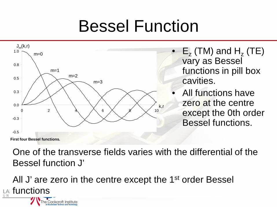
Bessel Function• Ez (TM) and Hz (TE)
vary as Bessel functions in pill box cavities.
• All functions have zero at the centre except the 0th order Bessel functions.
-0.5
-0.3
0.0
0.3
0.5
0.8
1.0
0 2 4 6 8 10
m=0
m=1m=2
m=3
Jm(kTr)
kTr
First four Bessel functions.
One of the transverse fields varies with the differential of the Bessel function J’
All J’ are zero in the centre except the 1st order Bessel functions

Transverse Kicks• The force on an electron is given by
• If an electron is travelling in the z direction and we want to kick it in the x direction we can do so with either– An electric field directed in x– A magnetic field directed in y
• As we can only get transverse fields on axis with fields that vary with Differential Bessel functions of the 1st kind only modes of type TM1np or TE1np can kick electrons on axis.
• We call these modes dipole modes
( )F e E v B= + ×
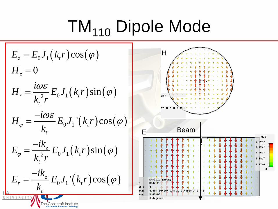
TM110 Dipole Mode( ) ( )
( ) ( )
( ) ( )
( ) ( )
( ) ( )
0 1
0 12
0 1
0 12
0 1
cos0
sin
' cos
sin
' cos
z t
z
r tt
tt
zt
t
zr t
t
E E J k rH
iH E J k rk r
iH E J k rk
ikE E J k rk rikE E J k rk
ϕ
ϕ
ϕ
ωε ϕ
ωε ϕ
ϕ
ϕ
=
=
=
−=
−=
−=
E
H
Beam

TE111 Dipole Mode( ) ( )
( ) ( )
( ) ( )
( ) ( )
( ) ( )
0 1
0 1
0 12
0 1
0 12
sin0
' sin
cos
' sin
cos
z t
z
zr t
t
zt
t
tt
r tt
H H J k rE
ikH H J k rkikH H J k r
k riE H J k rkiE H J k rk r
ϕ
ϕ
ϕ
ϕ
ϕ
ωµ ϕ
ωµ ϕ
=
=−
=
−=
=
−=
E
H Beam

If we rearrange Farday’s Law ( )and integrating along z we can show
Panofsky-Wenzel Theorem
( ) ( )( ) ( ) ( )00 0
,, , ,
zcL L
z zc c z
t
dE z tdz E z cB z c dz dt E z t
dz⊥
⊥ ⊥
+ = −∇
∫ ∫ ∫
dBEdt
∇× = −
( ) ( ) ( )00 0
,, ,
zcL L
zc z
t
E z tc dzB z c dz dt E z t
zτ ⊥
⊥
∂ = = −∇ ∂
∫ ∫ ∫Inserting this into the Lorentz transverse force equation gives us
for a closed cavity where the 1st term on the RHS is zero at the limits of the integration due to the boundary conditions this can be shown to give
( ) ( )( ) ( )( )00 0
, , ,z
cL Lz z
c c zt
dz E z cB z c dz dt E z t⊥ ⊥+ = − ∇∫ ∫ ∫

As the electrons have a large longitudinal energy we can approximate the kick from the magnetic field as equivalent to an electric field of magnitude E=cB. Hence we can define a transverse voltage
Panofsky-Wenzel Theorem( ) ( )( ) ( )( )
00 0
, , ,z
cL Lz z
c c zt
dz E z cB z c dz dt E z t⊥ ⊥+ = − ∇∫ ∫ ∫
( ) ( )( )0
, ,L
z zc cV dz E z cB z⊥ ⊥= +∫
( ) ||
0
, ~L
zcz m
mVic icV dz E zrω ω⊥ ⊥= − ∇ −∫
This means the transverse voltage is given by the rate of change of the longitudinal voltage (for particles travelling close to c).
( )( )00
,z
cL
zt
V c dz dt E z t⊥ ⊥= − ∇∫ ∫

Transverse Shunt Impedance
212 c
VR
P⊥
⊥ =
( ) 22 2||
2 2V rVR c
Q U U rω ω ω⊥ = =
||VicVrω⊥ == −
For dipole modes, m=1, so the transverse voltage is given by
For calculating required power we use a modified transverse shunt impedance definition
We also use a modified transverse R/Q definition (like when calculating dipole wakefields) except this definition is in the units of Ohms and is in a more convenient form for calculating power and energy requirements for deflecting cavities.

TE modes• The transverse kick is proportional to the rate of radial change in the
Ez field.• TE modes do not have longitudinal electric fields so they cannot kick
an electron beam.
• But the TE110 mode has transverse E and B fields what happens to their kick?
• The transverse kick due to the electric fields and the magnetic fields completely cancel each other out
• Note: for low beta cavities TE modes can be used for deflecting

Beam-Pipes
• The fields near the centre of the cavity becomes
When we add the beam-pipes the TM110 mode in the cavity couples to the TE11 mode of the beam-pipe.
( )2 2 2 sin cos ,4
sin cos ,2
cos cos ,
x
y
z
kE a x y z t
kE xy kz t
E x kz t
ω
ω
ω
εεε
= + −
=
=
2 2 2 2
cos sin ,2
1 ( ) ( )1 cos sin ,4 4
sin sin .
x
y
z
kcB xy kz t
ka k x ycB kz tk
cB y kz t
ω
ω
ω
ε
εε
=
−= − − +
= −

Fields seen on-axis
0
2000000
4000000
6000000
8000000
10000000
12000000
14000000
16000000
18000000
20000000
0 2 4 6 8 10 12 14Length (cm)
Tran
sver
se E
lect
ric F
ield
0.00E+00
1.00E+04
2.00E+04
3.00E+04
4.00E+04
5.00E+04
6.00E+04
7.00E+04
8.00E+04
9.00E+04
1.00E+05
Tran
sver
se M
agne
tic F
ield
H fieldE field
The electric and magnetic fields are 90 degrees out of phase in both space and time so that their kicks coherently add.
The electric field is in the iris and the magnetic field is in the cavity

Single-cell crab cavity

Applications of Deflecting Cavities
• Particle separation• Temporal beam diagnostics• Crab-crossing in colliders• X-ray pulse compression• Emittance exchange
• Choppers are very similar but will not be discussed here!

Transverse Kick• If we apply a kick of voltage Vt to a charged particle it
gain a transverse energy qVt• If the electron has a longitudinal energy E0 then the
electron will have a trajectory with angle,
– x’ = arctan(qVt/E0) ~ qVt/E0
• The transfer matrix element R12 relates the final offset x to the initial angle x’ hence
– x = R12 qVt/E0
eVtx’E0 E0
Crab cavity

Kick or rotationAs the transverse kick varies sinusoidally in time, the finite bunch width means that each part of the bunch receives a different kick. If the centre of the bunch issynchronised to pass throughthe cavity at the zero crossing,the head and tail of the bunchwill receive equal and oppositekicks. Causing the bunch toappear to rotate as it travelstowards its destination.
If a cavity is in rotating phase we call it a crab cavity

Particle Separators• The earliest use of
transverse deflecting cavities were particle separators. There are two different schemes for its use.
1. Can separate different bunches to send them to different experiments
2. Can separate out different particle species in a bunch
1 1
K
Lc π
φ ωβ β
∆ = −
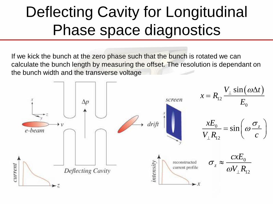
Deflecting Cavity for Longitudinal Phase space diagnostics
If we kick the bunch at the zero phase such that the bunch is rotated we can calculate the bunch length by measuring the offset. The resolution is dependant on the bunch width and the transverse voltage
0
12
sin zxEV R c
σω⊥
=
0
12z
cxEV R
σω ⊥
≈
( )12
0
sinV tx R
Eω⊥ ∆
=

• Use transverse-deflecting rf cavities to impose a correlation (“chirp” between the longitudinal position of a particle within the bunch and the vertical momentum.
• The second cavity is placed at a vertical betatron phase advance of nπ downstream of the first cavity, so as to cancel the chirp.
• With an undulator or bending magnet placed between the cavities, the emitted photons will have a strong correlation among time and vertical slope.
• This can be used for either pulse slicing or pulse compression.
Slitting
∆yθ
α
A. Zholents, P. Heimann, M. Zolotorev, J. Byrd, NIM A 425(1999), 385
X-ray pulse compression
X-ray Pulse Compression

Can get the same compression as long as h*V is constant
Higher h and lower V: smaller maximum deflection and less lifetime impact
Higher V and lower h: more linear chirp and less need for slits
Higher h and maximum V: shortest pulse, acceptable lifetime
Frequency Choice in Crab Cavities
Cavity design and rf source issues
h=7, V<6 MV?
V=4, h=6V=6, h=4
V=6, h=8
Beam dynamics simulation study: h ≥ 4 (1.4 GHz) V ≤ 6 MV (lifetime)

Emittance Exchange• TM110 dipole cavities also have a
longitudinal electric field which is zero on axis and varies linearly with transverse offset.
If we pass a beam through some dipole magnets the beam will spread out dependant on the bunch energy
We then pass the beam through a dipole cavity and accelerate /decelerate electrons based on transverse position reducing longitudinal emittance.
The beam will however get some transverse spread due to the transverse fields hence the longitudinal and transverse emittance is exchanged.

Emittance Exchange
1k = η
McBB
B
B1k = ηThin Transverse Cavity
Dog-Leg for generating dispersion
McBB
B
B Approximate Exchange (M.Cornacchia & P. Emma)
1k = η
B Exact Exchange (KJK)

Crab Cavities for CollidersHead-on collisionMaximum luminosity
Crossing angle introducedReduced luminosity due to crossing angle
Crossing angle with crab rotationEffective head-on collision
-1/2

Crab Cavities in Circular Machines• For circular machines the bunches
obviously pass through the crab cavity multiple times.
• If we use a single crab cavity the beam will oscillate about the ring which may cause problems for collimation.
• This is known as a global scheme and is utilised at KEKB.
• If collimation is problematic for a global scheme we can use two crab cavities both placed at a phase advance of π/2 from the IP on either side.
• One cavity crabs the beam and the other un-crabs it such that it doesn’t oscillate about the ring.

Effect of distance between crab cavity and focusing quadrupole
QF1 QD0
QF1 QD0α
α
Position of the crab
cavity
Trajectory of a particle at one end of
the bunch
x1
Deflection x1>x2
x2
Angle given bycrab kick
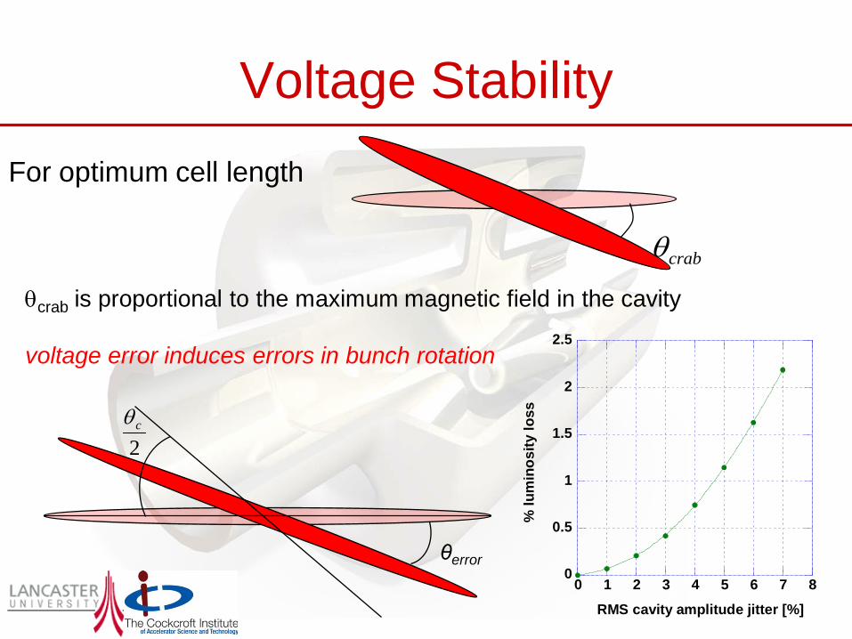
Voltage Stability
θcrab is proportional to the maximum magnetic field in the cavity
voltage error induces errors in bunch rotation
crabθ
For optimum cell length
θerror
2cθ
0
0.5
1
1.5
2
2.5
0 1 2 3 4 5 6 7 8
% lu
min
osity
loss
RMS cavity amplitude jitter [%]

Absolute cavity phase error
Phase error (deg) for 2% luminosity loss
Crossing angle
for cavity frequency
1.3GHz 3.9GHz10mrad 6 1920mrad 3 9
∆x IP displacedIP
Collision point
Absolute cavity phase error is not a
major concern

0
1
2
3
4
5
6
7
0 0.02 0.04 0.06 0.08 0.1 0.12
% luminosity loss% luminosity loss
% lu
min
osity
loss
RMS cavity timing jitter [ps]
Crab cavity phase tolerances
∆−
=2
2
4 x
x
eS σ
Δx
Interaction point
electron bunch
positron bunch
Typically set for <2% luminosity loss (S=0.98)
For ILC nominal parameters σx=639nm, ∆x=181nm, ∆t=86 fsec
ILC phase tolerance ~80 fsec, state of the art.
Luminosity reduction factor
cxt
cθ∆
≈∆2
The allowed timing error
Relative phase tolerance between the crab cavities on electron and positron side of the IP is critical as it will cause an x-offset between the beams.
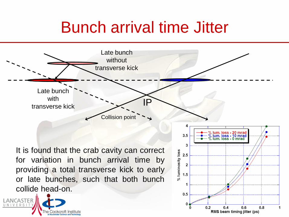
Bunch arrival time Jitter
It is found that the crab cavity can correctfor variation in bunch arrival time byproviding a total transverse kick to earlyor late bunches, such that both bunchcollide head-on.
IP
Late bunch without
transverse kick
Late bunch with
transverse kickCollision point