rf430cl330h practical antenna design · pdf filethe rf interface supports data rates up to ......
TRANSCRIPT

Application ReportSLOA197–June 2014
RF430CL330H Practical Antenna Design Guide
Kostas Aslanidis and Eddie LaCost
ABSTRACTThe Texas Instruments RF430CL330H Dynamic NFC Interface Transponder is a NFC Forum Type 4BTag Platform operating at 13.56 MHz (HF band). The device provides the flexibility to be used incombination with various antennas to meet the application performance requirements.
The scope of this document is to provide a short practical guide on the basic antenna design approach.
Figure 1. RF430CL330HTB Board
Contents1 RF430CL330H Dynamic NFC Interface Transponder .................................................................. 22 RF Interface .................................................................................................................. 43 RF430CL330HTB Target Board ........................................................................................... 54 Internal Resonance Capacitor ............................................................................................. 75 Antenna ...................................................................................................................... 76 Antenna Resonance Circuit ................................................................................................ 87 Antenna Q Factor ............................................................................................................ 98 Resonant Frequency Detuning ........................................................................................... 109 References .................................................................................................................. 11Appendix A Antenna Inductance Calculation................................................................................. 12
List of Figures
1 RF430CL330HTB Board.................................................................................................... 1
1SLOA197–June 2014 RF430CL330H Practical Antenna Design GuideSubmit Documentation Feedback
Copyright © 2014, Texas Instruments Incorporated

NFCReader
Micro-controller
INTO
I2Cor
SPI RF430NFCTag
RF430CL330H Dynamic NFC Interface Transponder www.ti.com
2 Typical Application........................................................................................................... 23 Functional Block Diagram .................................................................................................. 34 Typical Circuit for I2C ....................................................................................................... 35 Typical Circuit for SPI ....................................................................................................... 46 RF Interface Module......................................................................................................... 47 RF430CL330HTB Reference Schematic ................................................................................. 58 RF430CL330HTB Reference PCB Layout ............................................................................... 69 Target Board Modifications ................................................................................................. 610 Target Board Antenna Connection ........................................................................................ 711 Target Board Antenna Connection ........................................................................................ 812 Inductance vs. Resonance Capacitance Values ........................................................................ 813 Frequency and Bandwidth Measurement Fixture ....................................................................... 914 Antenna Q Measurement.................................................................................................. 1015 Read Range vs. Detuning................................................................................................. 1016 Antenna Coil Calculation .................................................................................................. 12
List of Tables
1 Internal Resonance Capacitor ............................................................................................. 72 Antenna Inductance (fres ~13.7MHz)....................................................................................... 7
1 RF430CL330H Dynamic NFC Interface Transponder
1.1 IC OverviewThe Texas Instruments Dynamic NFC Interface Transponder RF430CL330H is an NFC Tag Type 4 devicethat combines a wireless NFC interface and a wired serial peripheral interface (SPI) or inter-integratedcircuit (I2C) interface to connect the device to a host. The NDEF message in the SRAM can be writtenand read from the integrated SPI or I2C serial communication interface (for example, via a microcontroller)and can also be accessed and updated wirelessly via the integrated ISO14443B-compliant RF interface.The RF Interface supports data rates up to 848 kbps. The device allows for applications including, but notlimited to, NFC connection handover for an alternative carrier like Bluetooth®, Bluetooth Low Energy(BLE), and Wi-Fi® as an easy and intuitive pairing process or authentication process with only a tap. As ageneral use NFC interface, the RF430CL330H enables end-equipment to communicate with the fastgrowing infrastructure of NFC-enabled smart phones, tablets, and notebooks.
Figure 2. Typical Application
Bluetooth is a registered trademark of Bluetooth SIG, Inc.Wi-Fi is a registered trademark of Wi-Fi Alliance.
2 RF430CL330H Practical Antenna Design Guide SLOA197–June 2014Submit Documentation Feedback
Copyright © 2014, Texas Instruments Incorporated

1VCC
2ANT1
3ANT2
4RST
5E0
6E1
7E2
8INTO
9SCMS/CS
10SCK
11SO/SCL
12SI/SDA
13VCORE
14VSS
CTune
C1
C2
CCoreAntenna
External Reset (optional)
I2C Address Select
SDA
SCL
I2C Address Select
I2C Address Select Interrupt Output
select I2C
n/a for I2C
VCC
I2C/SPIInterface
ProcessingUnit
(MSP430-based)
ISO 14443BRF
Interface
NDEFMemory(SRAM)
SCL/SO
SDA/SI
SCK
E0 E1 E2 INTO
ANT1
VCC
VSS
VCORE
ANT2SCMS/CS
RST
www.ti.com RF430CL330H Dynamic NFC Interface Transponder
Figure 3. Functional Block Diagram
Figure 4. Typical Circuit for I2C
3SLOA197–June 2014 RF430CL330H Practical Antenna Design GuideSubmit Documentation Feedback
Copyright © 2014, Texas Instruments Incorporated
1
2
fresL Cp
=
* * *
ISO 14443B
RF
Interface
ANT1
ANT2
1VCC
2ANT1
3ANT2
4RST
5E0
6E1
7E2
8INTO
9SCMS/CS
10SCK
11SO/SCL
12SI/SDA
13VCORE
14VSS
CTune
C1
C2
CCoreAntenna
External Reset (optional)
SI
SCK
CS
SO
Interrupt Outputn/a for SPI
VCC
SPI Mode Select
SPI Mode Select
RF Interface www.ti.com
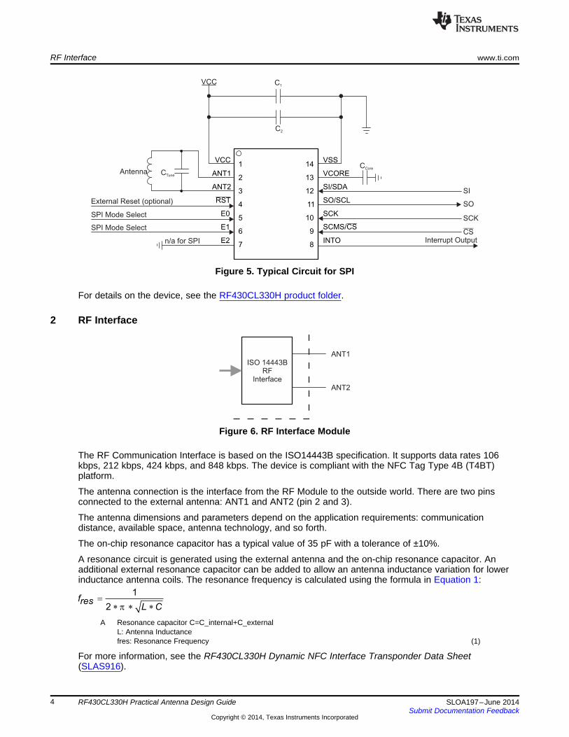
Figure 5. Typical Circuit for SPI
For details on the device, see the RF430CL330H product folder.
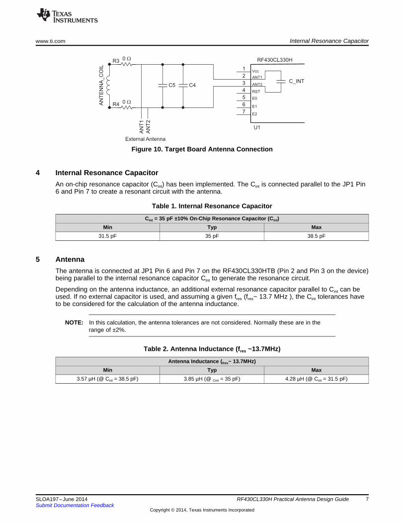
2 RF Interface
Figure 6. RF Interface Module
The RF Communication Interface is based on the ISO14443B specification. It supports data rates 106kbps, 212 kbps, 424 kbps, and 848 kbps. The device is compliant with the NFC Tag Type 4B (T4BT)platform.
The antenna connection is the interface from the RF Module to the outside world. There are two pinsconnected to the external antenna: ANT1 and ANT2 (pin 2 and 3).
The antenna dimensions and parameters depend on the application requirements: communicationdistance, available space, antenna technology, and so forth.
The on-chip resonance capacitor has a typical value of 35 pF with a tolerance of ±10%.
A resonance circuit is generated using the external antenna and the on-chip resonance capacitor. Anadditional external resonance capacitor can be added to allow an antenna inductance variation for lowerinductance antenna coils. The resonance frequency is calculated using the formula in Equation 1:
A Resonance capacitor C=C_internal+C_externalL: Antenna Inductancefres: Resonance Frequency (1)
For more information, see the RF430CL330H Dynamic NFC Interface Transponder Data Sheet(SLAS916).
4 RF430CL330H Practical Antenna Design Guide SLOA197–June 2014Submit Documentation Feedback
Copyright © 2014, Texas Instruments Incorporated

www.ti.com RF430CL330HTB Target Board
3 RF430CL330HTB Target BoardThe RF430CL330HTB is an evaluation platform for the RF430CL330H (NFC Type 4B Tag) device.Additional information on the target board can be found in the RF430CL330H Target Board User's Guide(SLOU373).
The Target Board allows the developers to design and test their systems and become familiar with theNFC T4T Type B protocol.
The Target Board is connected to a microcontroller board. The current board is designed to fit to a varietyof TI microcontroller platforms (for example, MSP-EXP430FR5739, http://www.ti.com/tool/msp-exp430fr5739), and can be directly connected via the RF1 and RF2 headers.
For test purposes, an “on-board” antenna is available on the Target Board. This antenna is connected tothe RF430CL330H IC pins, ANT1 and ANT2, through the two 0 Ω resistors, R3 and R4. The resistors areused to disconnect the on-board antenna, if a different external antenna is connected.
3.1 RF430CL330HTB Schematic
Figure 7. RF430CL330HTB Reference Schematic
5SLOA197–June 2014 RF430CL330H Practical Antenna Design GuideSubmit Documentation Feedback
Copyright © 2014, Texas Instruments Incorporated

RF430CL330HTB Target Board www.ti.com
3.2 RF430CL330HTB PCB Layout
A Design files are located at the following link:http://www.ti.com/lit/zip/slor112
Figure 8. RF430CL330HTB Reference PCB Layout
3.3 External Antenna ConnectionOn the RF430CL330HTB, it is possible to disconnect the “on-board” antenna and connect an externalantenna. The modifications to the board are as follows:1. Remove R3 and R4 (blue).2. Connect the external antenna at JP1 Pin 6 ANT1 and Pin 7 ANT2 (yellow).3. Use the C4 and C5 capacitors to adjust the new antenna to resonance frequency (red).
Figure 9. Target Board Modifications
6 RF430CL330H Practical Antenna Design Guide SLOA197–June 2014Submit Documentation Feedback
Copyright © 2014, Texas Instruments Incorporated
C5
1
2
3
4
5
6
7
U1
C_INTC4
R3
AN
TE
NN
A_C
OIL
0 W
R4 0 W
AN
T1
AN
T2
RF430CL330H
Vcc
ANT1
ANT2
RST
E0
E1
E2
External Antenna
www.ti.com Internal Resonance Capacitor
Figure 10. Target Board Antenna Connection
4 Internal Resonance CapacitorAn on-chip resonance capacitor (Cint) has been implemented. The Cint is connected parallel to the JP1 Pin6 and Pin 7 to create a resonant circuit with the antenna.
Table 1. Internal Resonance Capacitor
Cint = 35 pF ±10% On-Chip Resonance Capacitor (Cint)Min Typ Max
31.5 pF 35 pF 38.5 pF
5 AntennaThe antenna is connected at JP1 Pin 6 and Pin 7 on the RF430CL330HTB (Pin 2 and Pin 3 on the device)being parallel to the internal resonance capacitor Cint to generate the resonance circuit.
Depending on the antenna inductance, an additional external resonance capacitor parallel to Cint can beused. If no external capacitor is used, and assuming a given fres (fres~ 13.7 MHz ), the Cint tolerances haveto be considered for the calculation of the antenna inductance.
NOTE: In this calculation, the antenna tolerances are not considered. Normally these are in therange of ±2%.
Table 2. Antenna Inductance (fres ~13.7MHz)
Antenna Inductance (fres~ 13.7MHz)Min Typ Max
3.57 µH (@ Cint = 38.5 pF) 3.85 µH (@ Cint = 35 pF) 4.28 µH (@ Cint = 31.5 pF)
7SLOA197–June 2014 RF430CL330H Practical Antenna Design GuideSubmit Documentation Feedback
Copyright © 2014, Texas Instruments Incorporated
0.00
0.50
1.00
1.50
2.00
2.50
3.00
3.50
4.00
4.50
30 50 70 90 110 130
Inducta
nce
(uH
)
Resonance Capacitance Cres (pF) C001
L
Resonance CircuitL vs Cres at fres = 13.7 MHz
C5
1
2
3
4
5
6
7
U1
C_INTC4
R3
AN
TE
NN
A_C
OIL
0 W
R4 0 W
AN
T1
AN
T2
RF430CL330H
Vcc
ANT1
ANT2
RST
E0
E1
E2
External Antenna
Antenna Resonance Circuit www.ti.com
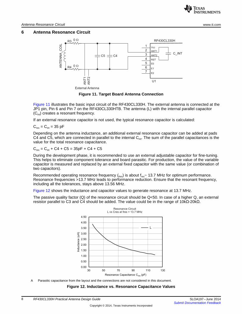
6 Antenna Resonance Circuit
Figure 11. Target Board Antenna Connection
Figure 11 illustrates the basic input circuit of the RF430CL330H. The external antenna is connected at theJP1 pin, Pin 6 and Pin 7 on the RF430CL330HTB. The antenna (L) with the internal parallel capacitor(Cint) creates a resonant frequency.
If an external resonance capacitor is not used, the typical resonance capacitor is calculated:
Cres = Cint = 35 pF
Depending on the antenna inductance, an additional external resonance capacitor can be added at padsC4 and C5, which are connected in parallel to the internal Cint. The sum of the parallel capacitances is thevalue for the total resonance capacitance.
Cres = Cint + C4 + C5 = 35pF + C4 + C5
During the development phase, it is recommended to use an external adjustable capacitor for fine-tuning.This helps to eliminate component tolerance and board parasitic. For production, the value of the variablecapacitor is measured and replaced by an external fixed capacitor with the same value (or combination oftwo capacitors).
Recommended operating resonance frequency (fres) is about fres~ 13.7 MHz for optimum performance.Resonance frequencies >13.7 MHz leads to performance reduction. Ensure that the resonant frequency,including all the tolerances, stays above 13.56 MHz.
Figure 12 shows the inductance and capacitor values to generate resonance at 13.7 MHz.
The passive quality factor (Q) of the resonance circuit should be Q<50. In case of a higher Q, an externalresistor parallel to C3 and C4 should be added. The value could be in the range of 10kΩ-20kΩ.
A Parasitic capacitance from the layout and the connections are not considered in this document.
Figure 12. Inductance vs. Resonance Capacitance Values
8 RF430CL330H Practical Antenna Design Guide SLOA197–June 2014Submit Documentation Feedback
Copyright © 2014, Texas Instruments Incorporated

13.67
349.1
39.15
MHzQ
kHz
Q
=
=
2 1BW f f
fresQ
BW
= -
=
www.ti.com Antenna Q Factor
7 Antenna Q FactorThe Antenna Q factor can be calculated with the formula shown in Equation 2. For the RF430CL330H,typical Q values should range from ~30 – 40.
(2)
The resonant frequency and bandwidth should be captured using a spectrum analyzer with trackinggenerator (such as Agilent E440x). The test fixture should consist of a pickup coil connected to the inputof the spectrum analyzer and a larger coil connected to the output of the spectrum analyzer trackinggenerator as shown in Figure 13.
The steps for the Spectrum analyzer Setup are as follows:1. Connect the fixture to the analyzer (the red connector to the output of the tracking generator, the blue
connector to the input channel).2. Place a reference unit on top of the fixture.
NOTE: The Antenna should to be centered and flat. The temperature and humidity will impactfrequency and Q of the antenna.
3. Enable the tracking generator output, centered to the expected transponder operating frequency (13.56MHz) with a span of 2 MHz.
4. At about –60dBm reference level with a vertical scale of 1 dB/div, the resonance curve will be shownas illustrated in Figure 13 and Figure 14.
5. View the bandwidth by enabling the N dB 3 points through the peak search menu.6. The quality factor is calculated by dividing the resonant frequency by the measured bandwidth. The
example in Figure 14 shows a Q value of ~39.
(3)
Figure 13. Frequency and Bandwidth Measurement Fixture
9SLOA197–June 2014 RF430CL330H Practical Antenna Design GuideSubmit Documentation Feedback
Copyright © 2014, Texas Instruments Incorporated

4.0
4.5
5.0
5.5
6.0
6.5
7.0
13.1 13.2 13.3 13.4 13.5 13.6 13.7 13.8 13.9 14.0 14.1 14.2
Co
mm
unic
atio
nD
ista
nce
(cm
)
Resonance Frequency (MHz) C002
EVM LargeDistance (cm)
Distance vsResonance Frequency Detuning
Resonant Frequency Detuning www.ti.com
Figure 14. Antenna Q Measurement
8 Resonant Frequency DetuningThe resonant frequency (in combination with a stable quality factor) should be tuned for the bestcommunication distance between reader and tag. Variation of the resonance frequency causesperformance degradation.
The variations normally come from the tags’ internal capacitor tolerances, antenna parameters,connections and external influences, such as metallic objects in close proximity.
Table 1 gives the internal resonance capacitor tolerances of the RF430CL330H IC. For practical reasons,it is recommended to compensate all the tolerances using an external capacitor connected between ANT1and ANT2. During the development phase, an adjustable capacitor can be used to fine tune for the bestcommunication distance. This capacitor can be replaced with a fixed value for the final product. It isdifficult to compensate the resonance frequency variations caused by unpredictable external influences inadvance as these are not known. In these cases, a special antenna design may be used to reduce theinfluences.
Figure 15 shows an example of influence of a detuned RF430CL330HTB over the communicationdistance using the TRF7970AEVM from TI: http://www.ti.com/tool/trf7970aevm.
Figure 15. Read Range vs. Detuning
10 RF430CL330H Practical Antenna Design Guide SLOA197–June 2014Submit Documentation Feedback
Copyright © 2014, Texas Instruments Incorporated
www.ti.com References
9 References• RF430CL330H product folder: http://www.ti.com/tool/RF430CL330HTB• RF430CL330H Dynamic NFC Interface Transponder Data Sheet (SLAS916)• RF430CL330H Target Board User's Guide (SLOU373)• Missouri University of Science and Technology Inductance Calculators:
http://emclab.mst.edu/inductance/
11SLOA197–June 2014 RF430CL330H Practical Antenna Design GuideSubmit Documentation Feedback
Copyright © 2014, Texas Instruments Incorporated

( )2 2 2 2 2
2 22 202 2
N h h w w h w h wrL w h h w h ln w ln h ln w lnrect
w h a a
m m
p
é ùæ ö æ ö+ + + + æ öê úç ÷ ç ÷= - + + + - - + + ç ÷ê úç ÷ ç ÷ è øç ÷ ç ÷ê úè ø è øë û
W
H
www.ti.com
Appendix A Antenna Inductance Calculation
Figure 16. Antenna Coil Calculation
• N: number of turns• w: width of the rectangle• h: height of the rectangle• a: wire radius• μr: relative permeability of the medium
(4)
More information regarding the antenna calculation methods can be found online:http://emclab.mst.edu/inductance/.
12 RF430CL330H Practical Antenna Design Guide SLOA197–June 2014Submit Documentation Feedback
Copyright © 2014, Texas Instruments Incorporated

IMPORTANT NOTICE
Texas Instruments Incorporated and its subsidiaries (TI) reserve the right to make corrections, enhancements, improvements and otherchanges to its semiconductor products and services per JESD46, latest issue, and to discontinue any product or service per JESD48, latestissue. Buyers should obtain the latest relevant information before placing orders and should verify that such information is current andcomplete. All semiconductor products (also referred to herein as “components”) are sold subject to TI’s terms and conditions of salesupplied at the time of order acknowledgment.TI warrants performance of its components to the specifications applicable at the time of sale, in accordance with the warranty in TI’s termsand conditions of sale of semiconductor products. Testing and other quality control techniques are used to the extent TI deems necessaryto support this warranty. Except where mandated by applicable law, testing of all parameters of each component is not necessarilyperformed.TI assumes no liability for applications assistance or the design of Buyers’ products. Buyers are responsible for their products andapplications using TI components. To minimize the risks associated with Buyers’ products and applications, Buyers should provideadequate design and operating safeguards.TI does not warrant or represent that any license, either express or implied, is granted under any patent right, copyright, mask work right, orother intellectual property right relating to any combination, machine, or process in which TI components or services are used. Informationpublished by TI regarding third-party products or services does not constitute a license to use such products or services or a warranty orendorsement thereof. Use of such information may require a license from a third party under the patents or other intellectual property of thethird party, or a license from TI under the patents or other intellectual property of TI.Reproduction of significant portions of TI information in TI data books or data sheets is permissible only if reproduction is without alterationand is accompanied by all associated warranties, conditions, limitations, and notices. TI is not responsible or liable for such altereddocumentation. Information of third parties may be subject to additional restrictions.Resale of TI components or services with statements different from or beyond the parameters stated by TI for that component or servicevoids all express and any implied warranties for the associated TI component or service and is an unfair and deceptive business practice.TI is not responsible or liable for any such statements.Buyer acknowledges and agrees that it is solely responsible for compliance with all legal, regulatory and safety-related requirementsconcerning its products, and any use of TI components in its applications, notwithstanding any applications-related information or supportthat may be provided by TI. Buyer represents and agrees that it has all the necessary expertise to create and implement safeguards whichanticipate dangerous consequences of failures, monitor failures and their consequences, lessen the likelihood of failures that might causeharm and take appropriate remedial actions. Buyer will fully indemnify TI and its representatives against any damages arising out of the useof any TI components in safety-critical applications.In some cases, TI components may be promoted specifically to facilitate safety-related applications. With such components, TI’s goal is tohelp enable customers to design and create their own end-product solutions that meet applicable functional safety standards andrequirements. Nonetheless, such components are subject to these terms.No TI components are authorized for use in FDA Class III (or similar life-critical medical equipment) unless authorized officers of the partieshave executed a special agreement specifically governing such use.Only those TI components which TI has specifically designated as military grade or “enhanced plastic” are designed and intended for use inmilitary/aerospace applications or environments. Buyer acknowledges and agrees that any military or aerospace use of TI componentswhich have not been so designated is solely at the Buyer's risk, and that Buyer is solely responsible for compliance with all legal andregulatory requirements in connection with such use.TI has specifically designated certain components as meeting ISO/TS16949 requirements, mainly for automotive use. In any case of use ofnon-designated products, TI will not be responsible for any failure to meet ISO/TS16949.
Products ApplicationsAudio www.ti.com/audio Automotive and Transportation www.ti.com/automotiveAmplifiers amplifier.ti.com Communications and Telecom www.ti.com/communicationsData Converters dataconverter.ti.com Computers and Peripherals www.ti.com/computersDLP® Products www.dlp.com Consumer Electronics www.ti.com/consumer-appsDSP dsp.ti.com Energy and Lighting www.ti.com/energyClocks and Timers www.ti.com/clocks Industrial www.ti.com/industrialInterface interface.ti.com Medical www.ti.com/medicalLogic logic.ti.com Security www.ti.com/securityPower Mgmt power.ti.com Space, Avionics and Defense www.ti.com/space-avionics-defenseMicrocontrollers microcontroller.ti.com Video and Imaging www.ti.com/videoRFID www.ti-rfid.comOMAP Applications Processors www.ti.com/omap TI E2E Community e2e.ti.comWireless Connectivity www.ti.com/wirelessconnectivity
Mailing Address: Texas Instruments, Post Office Box 655303, Dallas, Texas 75265Copyright © 2014, Texas Instruments Incorporated