rfi subtraction with a reference horn… f. briggs & m. kesteven illustrations from parkes...
Post on 19-Dec-2015
214 views
TRANSCRIPT

RFI Subtraction with a reference horn…
F. Briggs & M. Kesteven
• illustrations from Parkes Telescope… (Jon Bell et al.)
• origins in Int-Mit group at CSIRO – ATNF
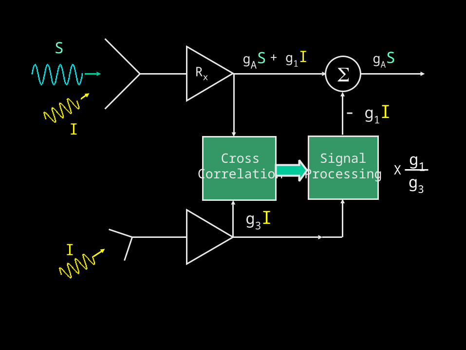
Rx
gASS
I
+ g1I
I
g3I
- g1I
SignalProcessing
gAS
g1g3
XCross
Correlation

R F I

Reference Antenna
I
I(t) = h(t) * io(t
Impulse Response h(t) for each path
Convolution operator
Signal radiated by transmitter
… with DELAY

= G(f) Io(f)
I(f) = (G(f) e-i2f ) Io(f)
Reference Antenna
I
TimeDomain
FrequencyDomain
I(t) = h(t) * io(t

Cross correlation: single polarization feed with 2 reference signals
1. Pol A
3. Ref 1
4. Ref 2
…G1 G4* | Io2|
G3 G4* | Io2|
?? G1G3
= G1 G4* | Io2|
G3 G4* | Io2|
G1G3
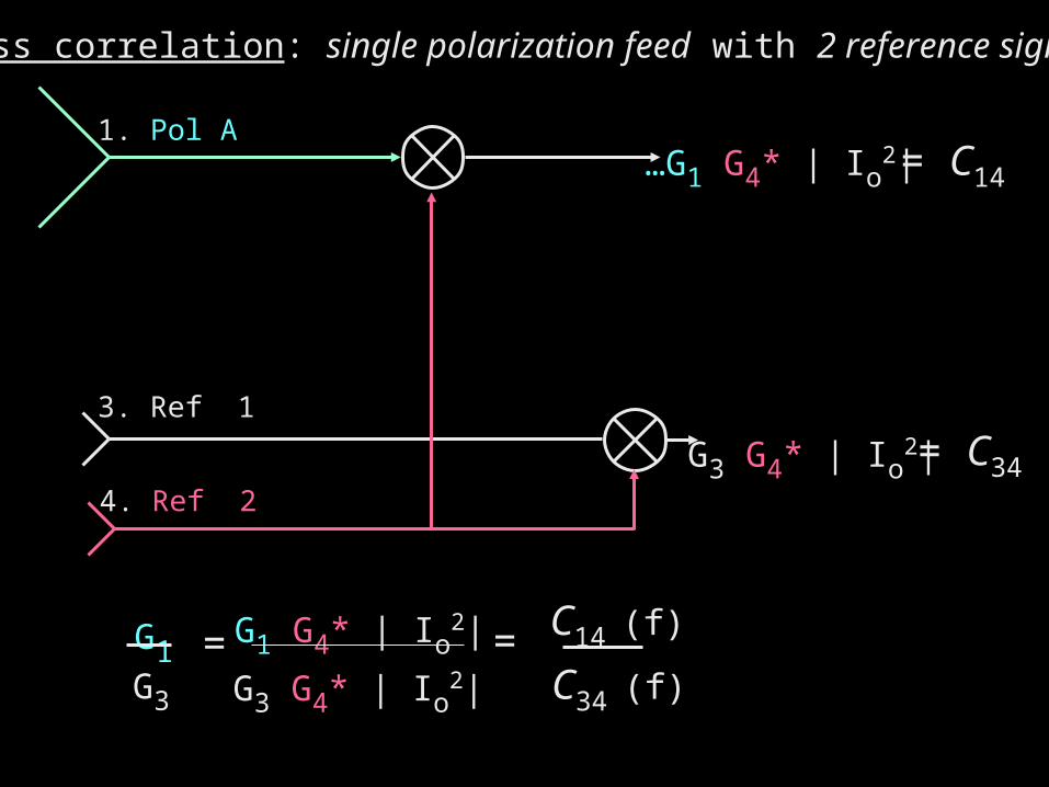
Cross correlation: single polarization feed with 2 reference signals
1. Pol A
3. Ref 1
4. Ref 2
…G1 G4* | Io2|
G3 G4* | Io2|
G1G3
= G1 G4* | Io2|
G3 G4* | Io2|
= C14 (f)
C34 (f)
= C14
= C34

Practical Application: Auto-Correlation Spectrometer
|gA2||S2|S
I
A/Cspectrometer
+ |g12| |I2|
|g12| |I2| =
Power Spectrum P(f)
g1g3* |I2| g4g1* |I2|
g4g3* |I2|=
C13(f) C14*(f)
C34*(f)
Advantage:
Cross Correlation Spectra NO BIAS due to NOISE power

Cross correlation: single polarization feed with 2 reference signals
1. Pol A
3. Ref 1
4. Ref 2
G1 G3* | Io2|
G1 G4* | Io2|
G3 G4* | Io2|
= C14
= C34
|g12| |I2| =
C13(f) C14*(f)
C34*(f)
= C13
A/C SpectrumContamination

Cross correlation: dual polarization feed with 2 reference signals
1. Pol A
2. Pol B
3. Ref 1
4. Ref 2
G1 G3* | Io2|
G1 G4* | Io2|
G2 G3* | Io2|
G2 G4* | Io2|
G3 G4* | Io2|
= C13
= C34
= C14
= C23
= C24
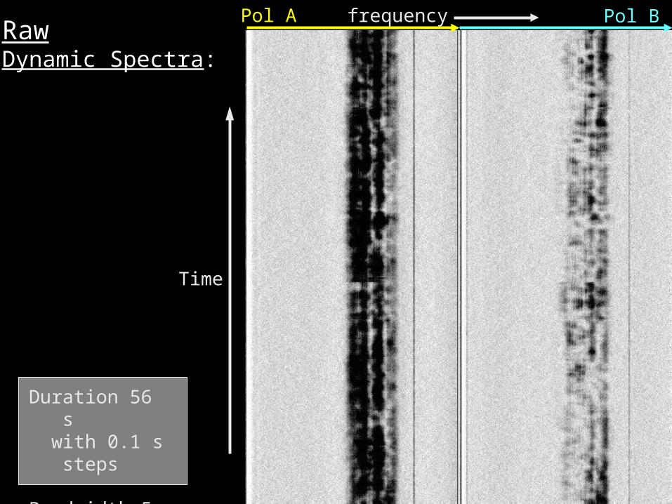
Duration 56 s with 0.1 s
steps
Bandwidth 5 MHz
RawDynamic Spectra:
Time
Pol A Pol Bfrequency
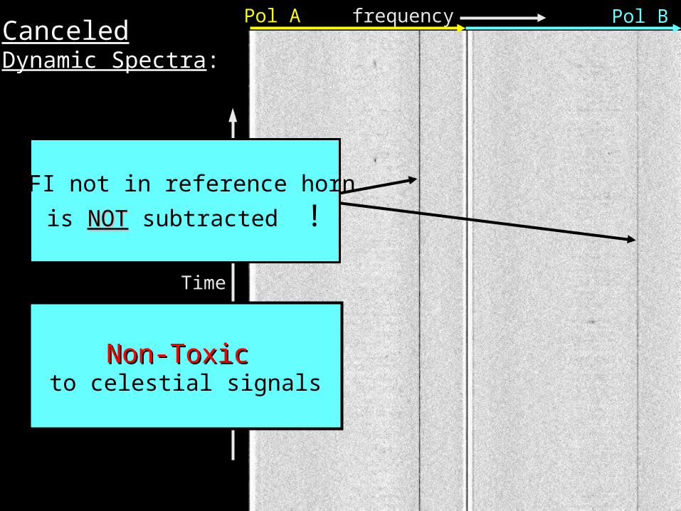
Pol A Pol BfrequencyCanceledDynamic Spectra:
Time
RFI not in reference horn
is NOTNOT subtracted !
Non-Toxic Non-Toxic to celestial signals

Spectral Domain Contamination: the VOLTAGEVOLTAGE spectrum
Estimate { g1(f) I(f) } = X13(f) g3(f) I(f)
C14(f)
C34(f)
stable on 0.1 second time scale
Update every second 1 f
Time Domain Contamination:
Estimate { gI(t) } = x(t) * gI(t
Ref Horn
Effectively… FIR filterFIR filter coefficients

Tim
e 0
.1 s
ec
step
s
FIR Coefficients + Delay 0.1s steps

Pol A Pol B
using Ref. “3”
using Ref. “4”

Phase
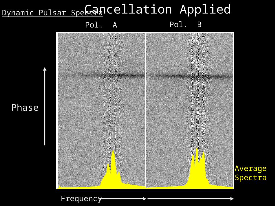
Dynamic Pulsar SpectraPol. A Pol. B
AverageSpectra
Frequency
Phase
Dynamic Pulsar Spectra
Pol. A Pol. B
Frequency
AverageSpectra
Cancellation Applied

Pulse Phase
SNR
RAW
Self-Norm
1 Cancelled
2 Cancelled
INTEGRATEDPULSE
PROFILES
uncorrected
cancelled
self- normalized

Phase
Dynamic Pulsar Spectra
Pol. A Pol. B
AverageSpectra
Frequency
Self-Normalized by Total Power Spectra

VLBI

VLBI
Westerbork
Jodrell Bank
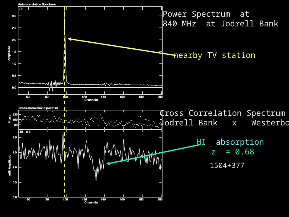
Power Spectrum at840 MHz at Jodrell Bank
nearby TV station
Cross Correlation SpectrumJodrell Bank x Westerbork
HI absorption z = 0.68
1504+377
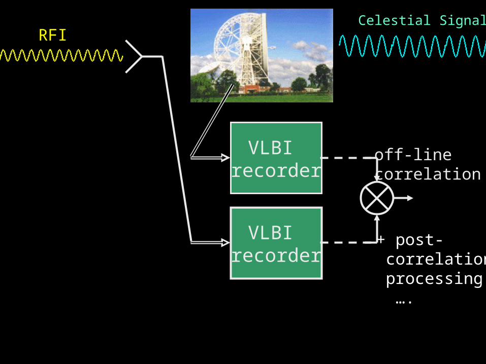
VLBI recorder
VLBI recorder
Celestial SignalRFI
off-linecorrelation
+ post- correlation processing ….

Conclusions
• complications of multi-path are contained in complex gains G(f)
• adaptive filtering with correlation functions preserves phase information….
… equivalent to subtraction of the voltage waveform