rgx305/305d/405/405d/505/505d generator … · model rgx305,305d rgx405,405d
TRANSCRIPT

Generator Model RGX305,305D
RGX405,405D RGX505,505 D
Technical Data & Overhaul Instructions

CONTENTS
Section Title Page
1. SPECIFICATIONS .......................................... 1
2. PERFORMANCE ........................................... 3
2-1 Model RGX305 ...................................... 3
2-2 Model RGX305D ..................................... 4
2-3 Model RGX405 ...................................... 5
2-4 Model RGX405D ..................................... 6
2-5 Model RGX505 ...................................... 7
2-6 Model RGX505D ..................................... 8
3. FEATURES .............................................. 9
4. GENERAL DESCRIPTION of GENERATOR ........................ 11
4 - 1 External View of Generator .............................. 11
4-2 Panel A ............................................ 12
4-3 Panel B ............................................ 13
5. CONSTRUCTION and FUNCTION ............................... 14
5-1 Construction ........................................ 14
5-2 Function ........................................... 15
5-3 Description of Generator Operation ......................... 21
5-4 Change of Engine Parts ................................. 25
6. SAFETY PRECAUTION ...................................... 28
7. APPLICABLE RANGE of GENERATOR ........................... 29
8. MEASURING PROCEDURE ................................... 32
8-1 Meters ............................................ 32
8-2 AC Output Measuring .................................. 34
8-3 DC Output Measuring .................................. 34
8-4 Insulation Resistance Measuring ........................... 34
9. CHECKING FUNCTIONAL MEMBERS. ........................... 36
9 - 1 Stator Assembly ...................................... 36
9-2 Rotor Assembly ...................................... 37
9-3 Brushes. ........................................... 38
9-4 AVR (Automatic Voltage Regulator) ........................ 38
9-5 No-Fuse Breaker and Fuse Holder .......................... 40
9-6 Receptacle and AC Plug ................................. 41
9-7 Voltmeters ......................................... 41
9-8 Diode Stack Assembly .................................. 41
9-9 Primary Exciting Circuit ................................ 42
10. DISASSEMBLY and REASSEMBLY .............................. 43
10 - 1 Preparations and Suggestions ............................. 43
10-2 How to Disassemble ................................... 43
10-3 How to Reassemble. ................................... 51
10-4 Control Box Disassembly and Reassembly ..................... 58
11. TROUBLE-SHOOTING ....................................... 59
12. OPTlON ................................................. 63
12 - 1 Electric Starter. ...................................... 63
12-2 Caster ............................................. 68
13. CIRCUIT DIAGRAM ........................................ 69

T .- Model - .- _-
Type
RGX305 RGX305D RGX405 RGX406D _-.. --- .-.... - __.-. ._ _ _-. _- --__. -- __-- - -. - .._-
Revolving-Field, Self-Exciting, P-pole, Single Phase _--.. .- Frequency
-. -_... _- 50Hz 60Hr
.-__ __ _.-.
3ooow 3400w 2500W 2900w
.-- -- 50Hr
.- .._
4ooow 3300w
- _-.-. 60HZ
-.--
4400w 3700w
-.. .- _ __ 50Hz
.__ _ ._ ._-
3ooow 2500W
- - -.. .._. .
Z ‘XA .-..
‘Z 2oZA -- ..- - ._ _
__-.- - 50Hz
- - .--
4ooow 3300w
1lOV
/ 22OV
120v
/ 240V
_ I - - - -
53.6A
/ 16.8A ,--.
30.8A
/ 15.4A -- .- i
1lOV
/ 220v
12ov
/ 240V
30.OA
/ 15.OA
26.4A .-._
24.2A -
- .-
- -,- I.
Power Factor .-.-_. -.
DC output - _---. -.
5 2 E ;
-.
ii G L W
._--.- 27.5A
/ 13.8A
.,-_. I---’ 240V 13.8A
I - I -- . I. - -A .- -- 1 -. .-.
1 .o - .- _ _..-. . ..- .- _- - _.. -- -.
12V 8.3A 1OOW ..-_ _-. ._ - - ..-. -, ., .-
AVR (Automatic Voltage Regulator) .- .- --.- -- .-.. .-_ _-. ._ -. ._--_. _-. -
Within 3%
.-. -. _. --. --- _ 7 - Voltage Regulator --- -.
Voltage Regulation --. . .,. ._- . -- ._
Tw -.. .- _. Model
- -__-, _.- --
Displacement _ .- _--
Max. Output -. -_,
Fuel _ -__. ..-
Fuel Tank Capacity -. ._.
Oil Capacity ,,.. .- . - ._- .-
Revolutions/min _ ._- . - - lgntition System
_....- -
Starting System _____ _ . _ ._
Fuel Consumption Ratio ..-. -
.-_
Irry Weight
.-. .- - ..- ._ - .- -- --_ ..- -_. _- ..-_.. _- _ _ __-_ . Robin Air-Cooled, 4.Cycle Gasoline Engine
. ..- --- ._-. . . - - -_. _- ~._ _--
EY25-2D(EY26-WI” -..- ._ -. ._. ____. __ ---
252 cc (15.40 cu. in) _- - _-. ,... _-
7HPl4000 rpm ._-_,. _ ___- 7
_- ---- . .._--- -
EY35DIWl-340)” - -- ,.. - _. -_- __.. __ _. __ - _
334 cc (20.39 cu. in) .--- _._ .- -. ..-.
8.5HP13600 rpm - _--_-,., - .- ..- _. .._ - _-.. . ._. .---. . ___. . -
Automobile Gasoline - _ _- .- -_ -. _ .-_. ___ ._- .- -
16 Liters (4.2 U.S. gall __ _. .--. - --..
I
_ ..-. . ._. .-- __--- - ..-.-
0.85 Liter (1.8 pints) 1.2 liters (2.6 pints) - _- .-. .- __- . - - _- _ _ _-_ .- ..-- -
50Hz-3000 rpm, 6OHr-3600 rpm -- - __,. _-. -_ .-- ._., ._-__, .- -. --- -., _..--- ..-. - _ ._ ._.- ._---
Robin Solid State Ignition Svstem ._-., _ .-_ .-. _- ..-__ .--.__ -... - .--.. ___.. .___ . -.. -
Recoil Starter (Electric Starter Optional) - -. ._ --. ..-. .- _-.. - _..-- .--. _- . -._ _.
1.7 Liters/Hr f50Hz), 1.9 Liters (60HzJ 2.2 LiterslHr f50Hz). 2.6 LiterslHr f60Hz) .-- -...- _-. _.-.. I -_ _ .--.. ---
681 mm (26.8 in) 706 mm 127.8 in) .-- .__.. _..- - _. ___ ~-- . . _
466 mm (18.3 in) 486 mm (19.1 in) -. - . _. .- . .-. .-.. _.-. .- ..--. -- . _-. . . .
661 mm (22.1 in) 596 mm (23.5 in) .--.. . . ..- _-- - _._-. _-.
62 kg (137 Ibs) 73.5 kg (162 Ibs.)
_.
“For U.S.A. and Canadian markets

I h) I
Model
Type
RGXSOB RGX505D
I I Revolving-Field, Self Exciting, 2-pole, Single Phase .
5 t 2 5 c)
-
; z w
- -.
,._. _- - -_ _ -_ ___, _ 50Hz
-
Max. 5ooOW Rated 4400w
I Power Factor I
.--_ 6OHZ
_--
5500w 4800W
1oov
/ 220v --
120
/ 240V - . .
1 .o - _- ----. --_. _. _- -. ---- _ DC Output 12V 8.3A 1OOW
- .-.__---...-- -- - -. -_-_ _.- .-__- - _ - --_ __ -___.__ __
Voltage Regulator AVR (Automatic Voltage Regulator) -~. _ -. -.-._- .-_- -_- --_, _
Voltage Regulation Within 3% -.- - .---- I-- - .---- - ._ -. ..- .- __.___- --__---
Type Robin Air-Cooled, 4-Cycle Gasoline Engine -. - _ - - --- - .-. ____m
Model -. - .- (Wl-350); EY40D -. - .---.. - - - - .--_- -.-- ,... - .- -. - _._____ --
Displacement 388 cc (23.68 cu. in) - --. - - .---.-, - - ,.- .-..-- ..-. - ,.- _
Max. Output lO.OHPl3600 rpm _.-- -. -._ _. .-, - .- --.--- --.
Fuel Automobile Gasoline .--. .-,-. .- -.--- ..- --- - .-. -._
Fuel Tank Capacity 16 liters (4.2 U.S. gal) - -.-.. -- -. .- - __ _- .___
Oil Capacity 1.2 liters (2.6 pints) --. .__- . . -. -._____ __ _ .-- .,----. _, _ ._
Revolutionlmin 50Hz-.3000 rpm, 60Hz-3600 rpm - ___. .-- __ ..-- .-._ - . -- .--. . - _- __. _. _-__
Ignition System Robein Solid State Ignition System
Starting System Recoil Starter (Electric Starter Optional) - ---- -. ,---.- - ---._ ---- --. -... -.. - .- .- -._-
Fuel Consumption Ratio 2.7 Liters/Hr (5OHr). 3.1 LiterslHr f60Hz) -- _- -. __- . -.. _- ._ ___ ,__ ,--.- ---_ _- .- -- ._-
Length 706 mm (27.8 in) - -. .-.- -.--_._ -, -.-.-
Iimensions Width 488 mm (19.1 in) -, --_.-.-.--. ,.
Height 596 mm (23.5 in) -. ---_._- - .---. ----
Dry Weight 77.5 kg (171 lb.?.)
--
l Enr I I C A snrl Panarlisn marLate

2. PERFORMANCE
2-l OUTPUT
MODEL RGX305.
Type . . . . . . . . . . . . . . . Self Exciting, 2-Pole, Single Phase
Power Factor . . . . . . . . . . 1 .O
Engine . . . . . . . . . . . . . . EY25-2D(EY25WI*
t 63
‘; 1;;62
,t z 61
2 60
2 59
7 $20
;;llO
%O
5
:
12 16 20 24 28 32
CURRENT(A) -
2 4 6 8 10 12 14
CURRENT(A) -
2 4 6 8 10 12 CURRENT(A)-
3
-- 2500 5
e
0’ .- 2000
-.1500
T 1500 t
:
1000
. . 3000
Output Max. ............... 3400W
Rated .............. 2900W
Frequency ................. 60Hz
Voltage ................... 11ov
Output Max. ............... 3000W
Rated .............. 2500W
Frequency ................. 5OHZ
Voltage ................... 220v
Output Max. ............... 3000W
Rated .............. 2500W
Frequency ................. 5OHZ
Voltage. .................. 240V
0’ bOo NOTE: These diagmms show the RGX305 characteristics at
I the main line frequencies and voltages. The characteristics
+ 1000 are similar to 6OHz 12OV, 5OHz 1 lOV, and 5OHz 230V.
*For U.S.A. and Canadian markets
-3-
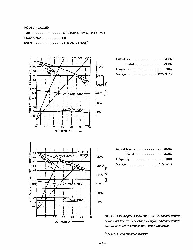
MODEL RGX305D
Type ............... Self Exciting, 2-Pole, Single Phase
Power Factor .......... 1 .O
Engine .............. EY25-2D (EY25W)”
t OUTPUT(240V). OUTPUT (12OV1
250
240
2230
ti
d 630
> 120
110
0 5 10 15 20 25 30
CURRENT(A)-
0 5 10 15 20 25 30
---I= I ‘n, A,, :rr&n\;\ I (11OV)
CURRENT(A)-
I 3000
t2500
1 t
: 2000 iii I !T I k 1 ‘1500 2
hO0
-c 500
Output Max. ............... 3400W
Rated .............. 2900W
Frequency ................. 6OHZ
Voltage ................ 12OVl24OV
I
I 3000
Output Max. . . . . . . . . . . . . . . . 3000W
Rated . . . . . . . . . . . . . . 2500W
Frequency . . . . . . . . . . . . . . . . . 5OHZ
-,2500 t
Voltage . . . . . . . . . . . . . . . . 11 OV/22OV
/E
-,2000 2
5
1
0 1500
NOTE: These diagrams show the RGX305D characteristics
at the main line frequencies and voltages The characteristics
are similar ro 6OHz 1 IOVB?OV, 6OHz 12OVR4OV.
“For U.S.A. and Canadian markets
- A-

MODEL RGX405
Type ...............
Power Factor ..........
Engine ..............
Self Exciting, 2-Pole, Single Phase
1.0
EY35D(Wl-340)*
I 120
ZllO
$00
2
G
CURRENT(A) -
<220- I I/.
w210- j , I y : I
g200* i i I I/: i i i I
I I
‘J 2 Y I
2 4 6 8
i I I
lo 12 14 16 18 CURRENT(A)-
I i 53
>- 0 2 52 Z- 5 51
g 50
a u. 49
-240 f
2 4 6 8 10 12 14 16 18
?4500
Output Max. ............... 44OOW
Rated .............. 3700W
I iNo”4
Frequency ................. 60Hz
Voltage ................... 11ov
+4000
13500
I :3OOoj
Output Max. ............... 4000W
Rated .............. 3300W
Frequency ................. 50Hz
220v Voltage ...................
i’”
2
i 1500
44000 Output Max. ............... 4000W
Rated .............. 3300W
Frequency ................. 50Hz
Voltage ................... 240V
t 2000
NOTE: mesa diagrams show tie RGX405 characteristics at
+ 1500 tie main line frequencies and voltages. The characteristics
are similar to 6OHz 12OV, 5OHz 1 lOV, and 5OHz 230 V.
*For U.S.A. and Canadian markets CURRENT(A)-
-5-
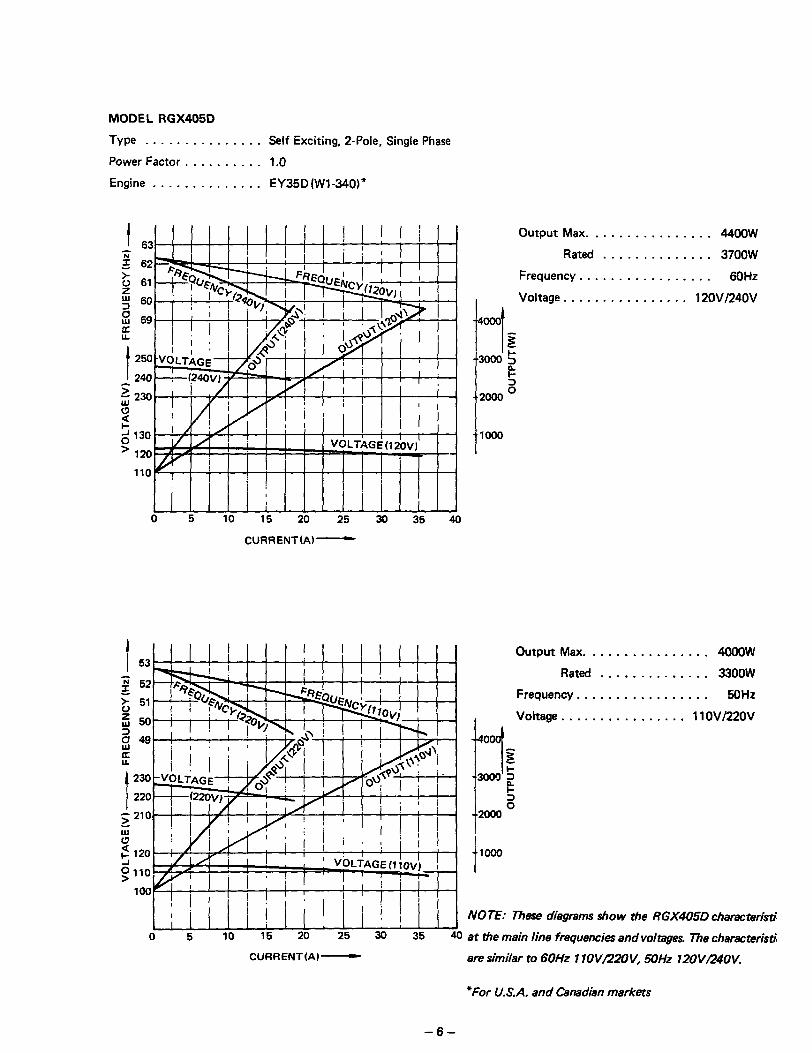
MODEL RGX405D
Type ...............
Power Factor ..........
Engine ..............
Self Exciting, 2-Pole, Single Phase
1.0
EY35D (Wl-340)’
--
62
61
60
59
f 240 250
5: z 230
0
2 J z 130
120
i : j 0 5 10 15 20 25 30 35 40
CURRENT(A)-
2 52
5 51
$50
2 49
2
1230 I
220
Output Max. .
Rated
Frequency. . .
i--i
Voltage . . . . .
s
I
3000 5
e
2000 s
t
1000
.............. 4400W
.............. 3700w
.............. 6OHZ
........... 12OV/24OV
Output Max. . . . . . . . . . . . . . . . 4000W
Rated . . . . . . . . . . . . . . 3300W
Frequency. . . . . . . . . . . . . . . . . 5OHZ
I
Voltage . . . . . . . . . . . . . . . . 11 OVl22OV
0
7 -2
t
5 0
2m
NOTE: These diagrams show the RGX405D characteristi
at the main line frequencies and voltages. The characterisri
CURRENT(A)- ara similar to 6OHz I lOVR2OV, 5OHz 12OVR4OV.
“For U.S.A. and Canadian markets
-6-

Self Exciting, 2-Pole, Single Phase
1.0
EY40D(Wl-390)”
MODEL RGX505
Type ...............
Power Factor ..........
Engine ..............
I I ;; ;; 62 62 E E > 6’ > 6’
+3 +3
p p
a a L L
t t 110 120 110 120
F F ;;;loo ;;;lOO
0 0
2 2
i I 1 ] 11 ! i
0 0 10 10 20 20 30 30 40 40 50 50
CURRENT(A) -
1 230 I , t / ,
i/ ’ ’ ’ 1 I 220 I ,< !
--V_OLTAGE ( : 7
0 5 10 15 20 25
CURRENT(AI-
A ; 53
3 t 52
2” 51
2 0 50
g 49 u.
1 250
5240 ‘3 13 230
2
0 5 10 15 20 25
I t
5000 Output Max. ............... 5500W
Rated .............. 4800W
-~I
I z ..3000 5
k
Frequency . . . . . . . . . . . . . . . . . 60Hz
Voltage . . . . . . . . . . . . . . . . . . . 1lOV
-5000
::I s: 3000 5
e
e.2000 2
Output Max. . . . . . . . . . . . . . . . 5000W
Rated . . . . . . . . . . . . . . 4400W
Frequency . . . . . . . . . . . . . . . . . 5OHZ
Voltage . . . . . . . . _ . . . . . . . . . . 220v
‘1000
t
Output Max. ............... 5000W
Rated .............. 4400W
Frequency ................. 5OHZ
Voltage ................... 240V
1000
I NOTE: These diagmms show the RGX505 characteristics at
the main line frequencies and voltages me characteristics
are similar to 6OHz 12OV, 5OHz 7 lOV, and 5OHz 23OV.
*For U.S.A. and Canadian markets CURRENT(A)-

MODEL RGX505D
Type ............... Self Exciting, 2-Pole, Single Phase
Power Factor .......... 1.0
Engine .............. EY40D (Wl-390)*
t sak,l ~rl?rv%!-kUT-I
11 i VI>
.--
240
z 230
; 2 130
g 120
110
0 10 20 30 40
CURRENT(A) -
t
230
220
z 210
ti 2 120
$110
100 I
i/I a.11
III”’ ijII ;i:i
0 10 20 30 40 50
CURRENT (A) -
1 5000 I
f4000
bo00
-*2000
-~looo
t 5000
t- i I
]
2 3000 5 “c
2000 0’
Output Max. ............... 5500W
Rated .............. 48OOw
Frequency ................. 60Hz
Voltage ................ 12OVl24OV
Output Max. ............... 5000W
Rated .............. 4400W
Frequency ................. 5OHZ
Voltage ................ 11 OVl22OV
t
1000
NOTE: These diagmms show tie RGX505D characteristics
at tie main line frequencies and voltages. The characteristics
are similar to 6OHz 1 lOVL22OV, 5OHz 12OVR4OV.
“For U.S.A. and Canadian markets
-8-
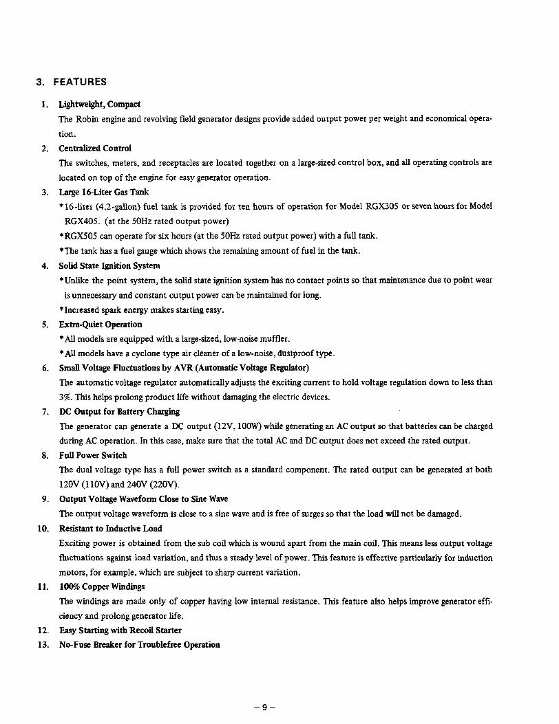
3. FEATURES
1.
2.
3.
4.
5.
6.
7.
8.
9.
10.
11.
12.
13.
Lightweight, Compact
The Robin engine and revolving field generator designs provide added output power per weight and economical opera-
tion.
Centralized Control
The switches, meters, and receptacles are located together on a large-sized control box, and all operating controls are
located on top of the engine for easy generator operation.
Large 16-Liter Gas Tank
* 16-liter (4.2-gallon) fuel tank is provided for ten hours of operation for Model RGX305 or seven hours for Model
RGX405. (at the 50Hz rated output power)
*RGX505 can operate for six hours (at the 5OHz rated output power) with a full tank.
*The tank has a fuel gauge which shows the remaining amount of fuel in the tank.
Solid State Ignition System
*Unlike the point system, the solid state ignition system has no contact points so that maintenance due to point wear
is unnecessary and constant output power can be maintained for long.
*Increased spark energy makes starting easy.
Extra-Quiet Operation
*All models are equipped with a large-sized, low-noise muffler.
*All models have a cyclone type air cleaner of a low-noise, dustproof type.
Small Voltage Fluctuations by AVR (Automatic Voltage Regulator)
The automatic voltage regulator automatically adjusts the exciting current to hold voltage regulation down to less than
3%. This helps prolong product life without damaging the electric devices.
DC Output for Battery Charging
The generator can generate a DC output (12V, 1OOW) while generating an AC output so that batteries can be charged
during AC operation. In this case, make sure that the total AC and DC output does not exceed the rated output.
Full Power Switch
me dual voltage type has a full power switch as a standard component. The rated output can be generated at both
12OV (11 OV) and 240V (22OV).
Output Voltage Waveform Close to Sine Wave
The output voltage waveform is close to a sine wave and is free of surges so that the load will not be damaged.
Resistant to Inductive Load
Exciting power is obtained from the sub coil which is wound apart from the main coil. This means less output voltage
fluctuations against load variation, and thus a steady level of power. This feature is effective particularly for induction
motors, for example, which are subject to sharp current variation.
100% Copper Windings
The windings are made only of copper having low internal resistance. This feature also helps improve generator effi-
ciency and prolong generator life.
Easy Starting with Recoil Starter
No-Fuse Breaker for Troublefree Operation
-9-

14. Ruggedly Built Frame
The box type frame is so ruggedly built that two or more generators can be stacked. Another convenient feature for
the Robin generators.
15. Wide Range of Options
The elctric starter type, wheels, and econo-throttle are availabe as options.
-10-
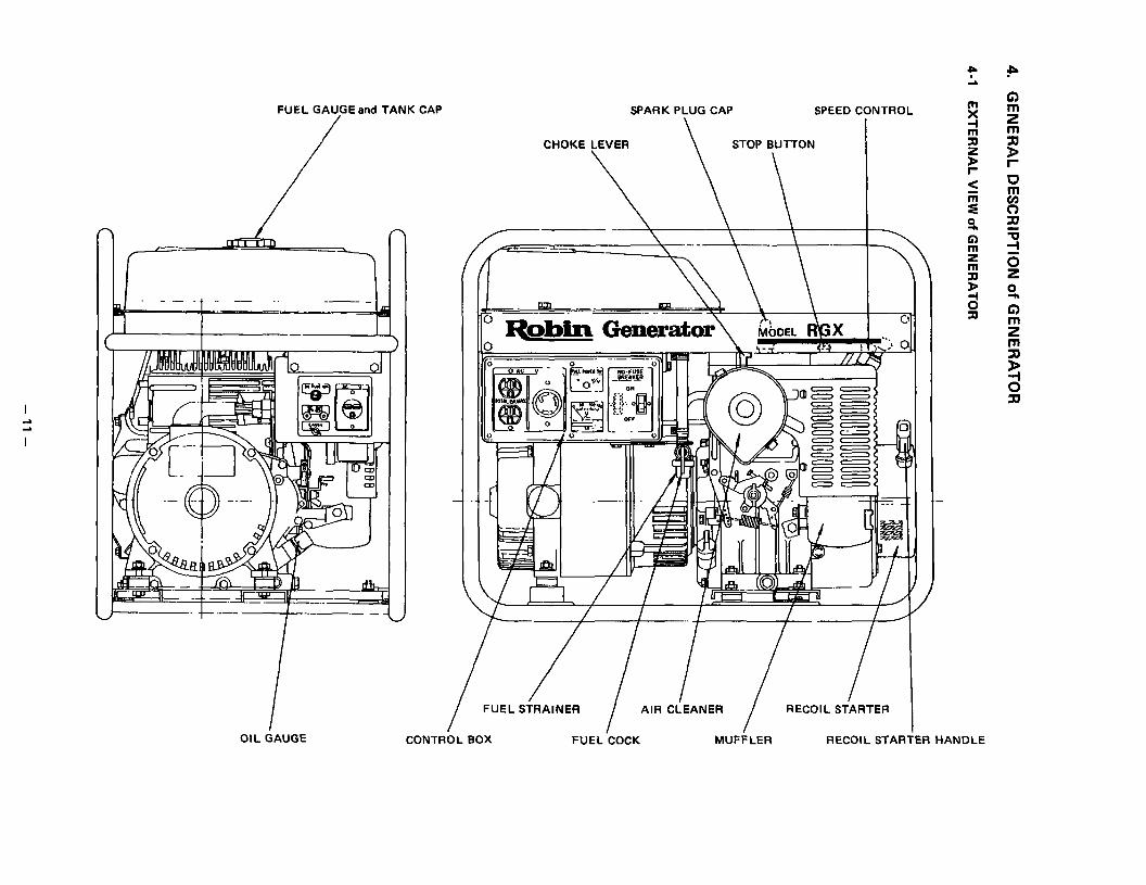
OIL GAUGE
FUEL GAU/GE and TANK CAP SPARK PLUG CAP SPEED CONTROL
CHOKE LEVER \ STOP BUTTON I
P L
s1 2 5)
E < ii z 3, G) s am 4; si
I FUEL STRAINER
I
AIR CLEANER
I
RECOIL STARTER
I CONTROL BOX FUEL COCK MUFFLER RECOIL STARTER HANDLE
P t) ?s E r
u m
t? 7[1 G i
i2 0
2
z”
i
3
si

4-2 PANEL A
‘0 f CAC V
AC RECEPTACLE 1 VOLTMETER NO-FUSE BREAKER
0 OAC V
-n -I Iv-l- “3C
JREAKER I
ON
0 0
-4 OFF
0
AC RECEPTACLE 1 / VOLTMETER No FUSE I~REAKER
AC RECEPTACLE 2
A ECEPTACLE 1 NO-FUSE ‘BREAKER
AC RECEPTACLE 2
FULL POWER SWITCH \
0 OAC V\
” , J) E I 0 / \ OJ
/ \ AC RECEPTACLE 1 VOLTMETER NO-FUSE BREAKER
AC RECEPTACLE 2
MODEL RGX305 22ov, 23ov, 240v RGX405 22ov, 23ov, 240v
MODEL ,RGX505
MODEL RGX305 RGX405 RGX505
MODEL RGX305D RGX405D RGX505D
22OV, 23OV, 240V
llOV, 12Ov llOV, 120v llOV, 120v
- 12 -

4-3 PANEL B
DC FUS
DC OUTPUT TERMINAL J
DC
EARTH (GROUND) TERMINAL
FUSE IOA
EARTH (GROUND) TERMINAL AC RECEPTACLE 3
MODEL RGX305 RGX405 RGX505
RGX305D RGX405D
RGX505D
EAR-iH (GROUND) TERMINAL AC R‘ECEPTACLE 3
- 13-

THROUGH BOLT SLIP RING COVER BOLT FRONT COVER SHAFT
I
I RUBBER MOUNT / ROTOR COMPL. I
ENGINE P.1 -..-..
‘.O.
I I I REAR ‘COVER STAi’OR COMPL. COOLI’NG FAN
H 8
q z
; ;;1 E =! -I
p 5 z
SHAFT
BkUSH HOLDER
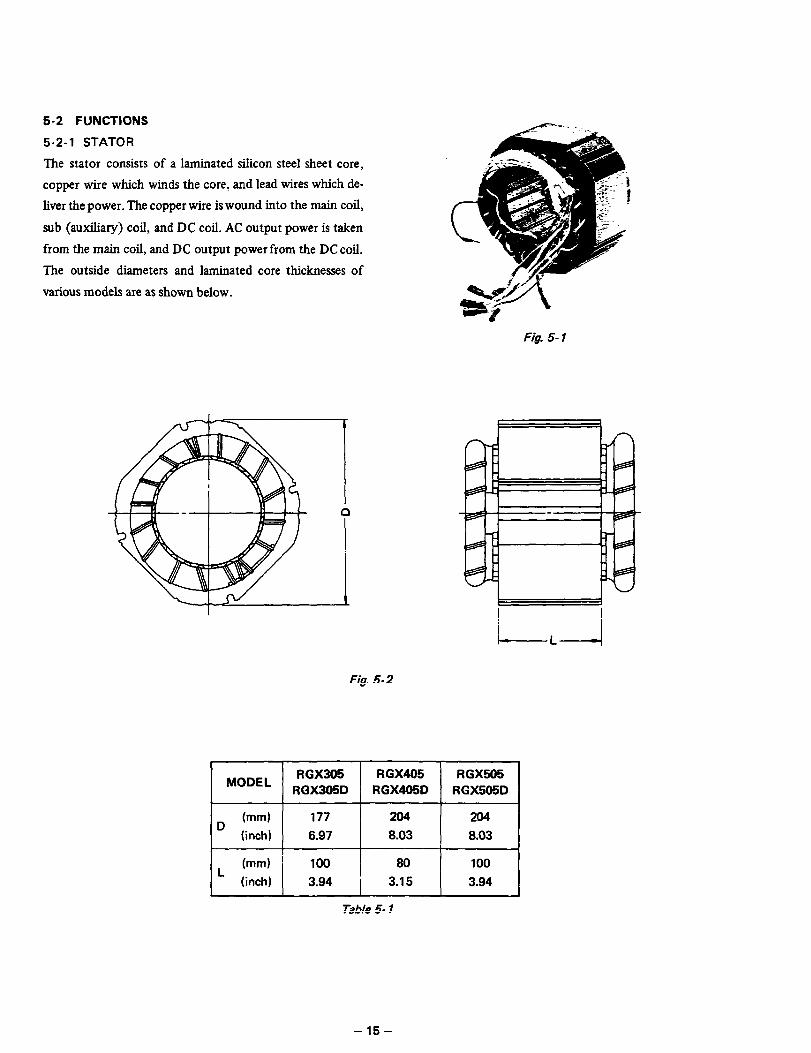
5-2 FUNCTIONS
5-2-l STATOR
-l-he stator consists of a laminated silicon steel sheet core,
copper wire which winds the core, and lead wires which de-
liver the power. The copper wire is wound into the main coil,
sub (auxiliary) coil, and DC coil. AC output power is taken
from the main coil, and DC output power from the DC coil.
The outside diameters and laminated core thicknesses of
various models are as shown below.
Fig. 5-1
Fig. 5-2
MODEL RGX305 RGX405 1 RGX505
RGX305D RGX405D 1 RGX505D
+yg+++j
Table 5- 1
- 15-

5-2-2 ROTOR
The rotor consists of a laminated silicon steel sheet cover
with a field coil wound arount it and cooling fans and slip
rings at both ends of the shaft. The field coil leads are con-
nected to the slip rings and direct current (DC) to the field
coil turns the rotor and magnet. The tooling fans cool the
generator by drawing cooling air from the slip rings and dis-
charging it through the fans.
.
FAN
SLIP RING
BEARING
Fig. 5-3
Fig. 5-4
MODEL I RGX305 RGX405 RGX505
RGX305D RGX405D RGX505D
d (mm) 99.6 118 118
(inch) 3.92 j 4.65 4.65
I bnml 100 80 loo
(inch) 3.94 3.15 3.94
Table 5-2
- 16 -

5-2-3 BRUSHES - - - ---------
An exciting current is supplied from the AVR to the rotor.
The brushes are made of carbon; and the brush-holders of
plastic. It is necessary to keep the contact pressure between
the brushes and slip rings withing specific limits. Thus, care
must be taken of brush length. (See 9-3 BRUSHES.)
5-2-4 AVR (AUTOMATIC VOLTAGE REGULATOR)
The automatic voltage regulator employs an electronic cir-
cuit to automatically regulate voltage.
5-2-5 VOLTMETER
The voltmeter comes in two types, a 150V maximum type
and a 300V maximum type. Type voltmeter indicates
generator output voltages. The generators with a generated
voltage of 1 lOV, 120V type and dual voltage type use the
15OV maximum type voltmeter; and those of 22OV, 23OV,
and 240V type specifications use the 300V maximum type
voltmeter.
RGX305. RGX305D RGX405. RGX405D RGX505, RGX505D
Fig. 5-5
RGX305, RGX305D
Fig. 5-6
RGX405, RGX405D RGX505, RGX505D
300 V MAX. 150 V MAX. (220 V. 230 V. 240 V) (110 v, 120 VI
Fig. 5-7
-17-

5-2-6 NO-FUSE BREAKER
The no-fuse breaker prevents AC output overcurrent and
shortcircuit overcurrent.
Some models have one no-fuse breaker, and the others have
two. The single no-fuse breaker protects the generator from
maximum current; and the double no-fuse breakers protect
the generator from maximum current, and its receptacles.
If the generator is operated for long above the maximum
current, the internal temperature of the generator abnormal-
ly rises to cause insulation deterioration, burning, electric NO-FUSE BREAKER
shock, and electric leakage. The no-fuse breaker protects FUSE HOLDER
the generator from such troubles. The receptacles and AC F&. 5-8
plug have their own rated capacities. (Refer to 5-2-8 RECEPTACLES AND PLUG.) If they are used above the rated
current, insulation deterioration, buring, electric shock, or leakage can occur. These troubles are prevented by the no-fuse
breaker.
Table 5-3 shows breaker capacities and protecting objects.
1
Model @eciiications N.F.B. Protecting Object N.F.B. Protecting Object
11ov 30A Maximum current RGX305
I 220V. 23OV. 240V I 15A (2P2E) Maximum current
RGX305D ( 110/22OV, 120/24OV ! 15A (2P2E) Maximum current
) 50Hz-1 lOV, 60Hz-120V ( 30A 1 Maximum current
I RGX405 !
60Hz-11ov : 35A ! Maximum current I I 22OV, 230V ! 20A(2P2E) j Maximum current I
I 240v ) 15A (2P2E) ’ Maximum current
I ; 110/22OV, 6OHz-120/240V ’ 20A (2P2E) I Maximum current
RGX405D i 5OHz-120/24OV ’ 15A(2P2E) j Maximum current 1
I 50Hz-11OV. 6OHz-120V 40A ; Maximum current 30A , 30A Receptacle
RGX505 : 22OV. 230V 25A(2P2E) i Maximum current
240V / 20A(2P2E) Maximum current
60Hz-11 ov 45A / Maximum current 30A 30A Receptacle
i RGX505D 1
110/22OV, 6OHz-120/240 25A (2P2E) 1 Maximum current 20A (2P2EI 3OA Receptacle
5OHz-120/24OV 20A (2P2E) 1 Maximum current
Table 5-3
l 2P2E means the bipolar doubleelemenr type, and if either of tw pairs
of currents running through tie no-fuse breaker exceeds the rated cur-
rent, the no-fuse breaker operates to turn power off.
The 22OV. 23OV, and 240V types use tie two pairs connected in series,
and the 1oOV and 120V type have them connected in parallel.
- 18 -

5-2-7 FUSE
The fuse prevents DC output overcurrent and shortcircuit overcurrent. If the generator is operated at a level exceeding the
maximum current, it can cause insulation deterioration. burning, electric shock. and electric leakage. The fuse protects the
generator from these troubles. Fuse capacity: 1 OA
5-2-8 RECEPTACLE and AC PLUGS
These are used for taking AC output power from the generator. A total of five kinds of receptacles, each varying in rated
voltage and current from another, are used. Each model has at least one receptacle to deliver the rated generator output.
As many AC plugs as the receptacles, each matching the corresponding receptacle, are provided. Table 5-4 shows the rated
current for each receptacle. Be careful not to use the receptacles and AC plugs beyond the specified limits to prevent burn-
ing. I
tz&@ / up to total i 5 amperes from two receptacles
@!
w j up to 15 amperes
I
;a; ]
‘aI
up to 20 amperes
I
up to 30 amperes (See Caution.)
Table 5-4
5-2-9 TERMINALS
The terminals are for producing DC output power, and
come in two colors, red and black. The red one is positive
(+), and the black one negative (-) .
5-2-10 FRONT COVER
The front cover is an aluminum die casting and is mounted
on the main bearing cover of the engine. It has vents to dis-
charge cooling air from the generator and the vents are de-
signed to prevent fingers from entering.
Ceution: Taking out power from TWIST LOCK RECEPTACLE, put rhe plug into ouflet end turn clockwise to lock it.
Fig. 5-9
RED BLACK
Fig. 5- 10
RGX405, RGX405D RGX305 RGX305D RGX505, RGX505D
Fig 5-17
- 19 -

5-2-l 1 REAR COVER
The rear cover is also an aluminum die casting, and has a
faucet joint to hold the stator together with the front cover.
It has bosses inside for holding the brushes, and slits for
taking cooling air in. The slits are so designed that human
fingers will not go in.
RGX305 RGX305C RGX405, RGX405D
RGX505, RGX505D
Fig. 5-12
5-2-12 RUBBER MOUNTS (RUBBER VIBRATION
ISOLATORS)
Rubber pads for controlling generator vibration and disloca-
tion. These are made of the most suitable rubber material
to optimum shape and hardness.
5-2-13 PIPE FRAME Fig. 5-73
The pipe frame consits of a pipe frame skeleton, side plates A and B, box stay, and air guide.
SIDE PLATE B
PIPE FRAME
SIDE PLATE A
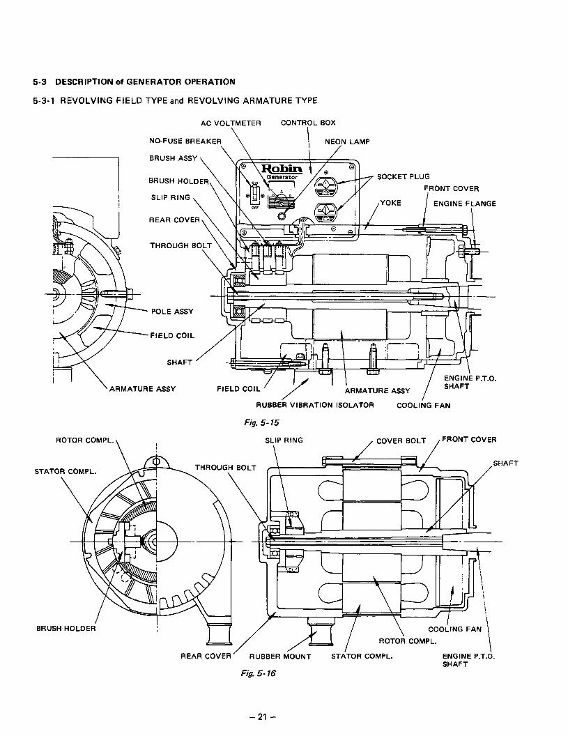
5-3-l REVOLVING FIELD TYPE and REVOLVING ARMATURE TYPE
I
AC VOLTMETER CONTROL BOX
.\ NO-FUSE BREAKER
BRUSH ASSY
BRUSH HOLDER
SLIP RING
REAR COVER
RfIl T
SOCKETPLUG
FRONT COVER
,YOKE I FNClhlF
POLE ASSY
FIELD COIL
SHAFT
ARMATURE ASSY FIELD COIL RMATURE ASSY
RUBBER VIBRATION ISOLATOR COOLll;G FAN
Fig. 5- 75
ROTOR COMPL. \ I
SLIP RING \ /
COVER BOLT /FRONT COVER
STATOR COMPL. SHA ,FT
r-r> I I 4 ! I I \
BRUSH HOLDER
ROTOR COMPL.
REAR COVER SHAFT
Fig. 5- 16
- 21 -

The RG Series is the revolving armature type, and the RGX Series is now the revolving field type. The differences between
these types and their features are described below. The construction of the revolving armature type is shown in Fig. 5- 15,
and that of the revolving field type in Fig. S- 16.
The basic operating principle of the generator is this. As a conductor moves in a magnetic flux (between poles N and S of a
magnet), a voltage is generated in the conductor and can be taken out as electric power. Generally, an electromagnet is used
for generators. The electromagnet consists of poles and field coils wound around them, and the poles become magnets as a
direct current runs through the field coils. The revolving armature type has static poles and a revolving armature which con-
sists of a conductor for taking electric power out. The revolution of the armature generates a voltage.
It was earlier explained that a conductor moves in a magnetic flux. Actually, however, a relative speed between the two is
sufficient for generating a voltage. That is, a voltage can also be generated by rotating the magnet while keeping the con-
ductor still.
The revolving field type falls in this latter category: The pole serving as an electromagnet rotattes, and armature which
consists of a conductor remains still.
The features of the revolving field type are as follows:
a)
b)
4
onlytwosliprings
As generator applications diversified, it became necessary for generators to meet increasingly varied conditions involv-
ing AC output, DC output, dual voltage, three-phase, and usefulness with induction motors. Accordingly, AC windings,
DC windings, auxiliary windings, etc. became necessary for generators. Because the revolving armature type takes elec-
tric power from the revolving part, it requires as many slip rings as the number of winding output terminals, and tbis
increases the generator dimensions. The revolving field type is small in size because it requires only two slip rings @r
feeding a current to operate the electromagnet.
Easy maintenance
As many brushes as the number of slip rings are necessary. The revolving field type is easier to maintain than the re-
volving armature type because it has fewer slip rings and brushes than the other.
Lightweight
The revolving armature type is heavy because it requires yokes to fm the poles and serve as flux passage. The revolving
field type is light in weight because the stator and rotor can be made by laminating steel sheets of the same material.
- 22 -

5-3-2 PRIMARY EXCITING ACTION
The RGX Series employs an exciting coil in the engine mag-
neto for raising the primary voltage. This action is explain-
ed. The RG Series generates a voltage when the generator is
started again because of the residual magnetism remaining
in the yokes and poles. If aienerator of this type is disas-
sembled and stored for a long period of time, the residual
FC
magnetism may dissipate so that the generator may not
generate a voltage when it is restarted. The RGX Series
has an exciting coil for primary exciting action to eliminate
such a phenomenon.
The primary exciting action of the new type is explained
below.
ENGINE MAGNETO
Fig. 5- 17(A)
When the generator is started, the permanent magnet on the
engine rotates to genrate a voltage in the exciting coil. This
voltage is regulated by a diode in the AVR to feed a current
to the generator field coil (FC). (See Fig. 517(A).)
The rotor is turned an electromagnet by that current and
rotates so that voltages are generated in the stator coils
(main coil, sub coil, and DC coil). The voltage generated in
the sub coils is operated by the AVR to feed a current to in-
crease the field coil current (See Fig. 5-17(B).) As a result,
the rotor magnetism increases. This operation is repeated to
generate the rated voltage at 5OHz or 6OHz in the main coil
and DC coil.
5-3-3 VOLTAGE REGULATING MECHANISM
Connect a load to the AC output terminal and increase cur-
rent. Output voltage varies as shown in Fig. 5-17(C) depend-
ing on whether an automatic voltage regulator is used or
not. The operation of the AVR is explained below.
When an AC output is taken, the engine is loaded and its
rpm falls. Also the AC voltage falls due to the voltage drop
caused by the internal resistance of the coils. The AVR
detects this voltage drop and its built-in SCR automatically
increases the current flows to the field coil. As a result, the
rotor magnetism increases, the voltage fallen by the load
current is raised, and the output voltage is kept constant. If
the AC output is reduced, the SCR operates in the opposite
way to similarly keep the output voltage constant.
I
MC A
SC
c 4
Fig. 5- 17/B)
WITHOUT AVR
RATED VOLTAGE
I WITH AVR
-A
Fig. 5 17(C)
- 23 -

5-3-4 FULL POWER SWITCH
The dual voltage type has a full power switch to produce the rated output from a single 11OV or 120V receptacle. The full
power switch operates as described below. (The full power switch for 12OV/24OV is described as the construction of both
full power switches for 12OV/24OV and 1 lOV/22OVis same.
240V
I i-J?-; i 7
Fig. 5-18 Fig. 5- 19
A circuit diagram of the conventional dual voltage type is Switch LOW VOLTAGE HIGH VOLTAGE
shown in Fig. 5 - 18, and a circuit diagram of the RGX RECEPTACLE RECEPTACLE I
Series’ dual voltage type which is fitted with a full power
switch is shown in Fig. 5-19. AC winding s MC1 and
MC2 generate a voltage of 120V each.
Fig. 5 - 18 shows MC1 and MC2 kept connected in series. In
this case, an output can be generated from either the 240V ’ I
Table 5-5 or 120V receptacle. The 240V receeptacle outputs the
rated output (or the maximum output in a short-time op-
eration), but one 120V receptacle can output only one half of the rated output. Since two 120V receptacles are provid-
ed: the rated output can be outputted by combining the outputs of the two 12OV receptacles.
The RGX Series shown in Fig. 5-19 changes the connection of MC1 and MC2 to series or parallel with the full power switch.
When the full power switch is shifted to the 12OV/24OV postion, the switch is up as indicated by the solid line in Fig. 5-19,
and connects MC 1 and MC2 in series as shown in Fig. 5-l 8. In this case, voltages up to the rated level can be outputted from
Receptacle 3, and voltages up to one half (12OV) of the rated voltage from Receptacle 1 and Receptacle 2. (If the rated cur-
rent is over 30A at 12OV, up to 15A can be outputted from Receptacle 1 as the combined output of the two.) When the full
power switch is shifted to the 120V position, the switch is down as indicated by the broken line in Fig. 5-19, and connects
MC1 and MC2 parallel to each other. In this case, no 240V can be outputted, and Receptacle 3 cannot be used. Receptacle
2, which outputs 120V can generate up to the rated power; and Receptacle 1 can output up to 15A in total (or up to 30A if
the rated current is over 30A at 120V). The above is summarized in Table 5-5. Use the full power switch as suitable to the
voltage and input ratings of the electric devices.
- 24 -

54 CHANGE of ENGINE PARTS
In detail of the engine, please refer to the service manual, RGX305, RGX305D are refer to EY25, RGX405, RGX405D,
RGX505 and RGX505D are refer to EY35 and EY40.
The RGX Series employs engine parts special to the RGX to suit the modified engine. The engine parts can be classified by -
ignition system, control system, fuel system, and cooling system. The engine parts for each of these systems are explained
below.
5-4-l IGNITION SYSTEM
All models of the RGX Series employ a solid state ignition system. For the RGX305, RGX305D, refer to the section on
EY25 CD1 in the Electrical Ignition Service Manual.
For the RGX405, RGX405D and RGX505, RGX505D, refer to the section on Robin Solid State Ignition in the EY35 and
EY40 Service Manuals.
All models use a primary exciting coil (or lighting coil) of special performance and lead length.
NOTE: Be careful not to use an exciting coil of different performance because it can damage theautomatic voltage regulator.
5-4-2 CONTROL SYSTEM
The control parts are centrally located to permit centralized control at the top of the engine. The parts added or changed
are as shown in Fig. 5-20.
LABEL
PLATE
CHOKE
Fig. 5-20(l)
- 25 -

The blower housing has nuts for mounting the bracket, and a wire for the stop button which runs inside the blower housing.
WIRE BLOWER HOUSING
Fig. 5-20 (21
5-4-3 FUEL’SYSTEM
The large-sized 164ter fuel tank is mounted in the frame. The fuel piping was changed as a result as shown in Fig. 5 -21.
FUEL GAUGE
FUEL TANK
/-+, RUBBER ’ ’ ’
to CARBURETOR /,
HOSE CLAMP
RUBBER PIPE 2
HOSE CLAMP
Fig. 5-27 \ FUEL STRAINER
- 26 -

5-4-4 COOLING SYSTEM
A baffle is provided to prevent engine cooling air from raising the temperature of other parts. Large sized rubber pipe 1
shown in Fig. 5 -21 prevents vapor lock even at high ambient temperature (up to about 45’C).
CAP (RUBBER)
HEAD COVER
TO MUFF
TO CARBURETOR
‘CYLINDER BAFFLE 3
RGX305, RGX305D
LEA
BAFFLE (CARBURETOR
RGX405, RGX405D RGX505, RGX505D
SIDE)
Fig. 5-22
5-4-5 OTHERS
The RGX405, RGX405D and RGX505, RGX505D are fitted with an iron plate under the engine to reduce vibration. The
oil dram parts shown in Fig. 5-23 are newly employed for these models to solve the problem of inconvenience in oil change.
CRANKCASE :-“l/;>SEAL WASHER PLUG
Fig. 5-23
- 27 -

6. SAFETY PRECAUTIONS
1. Use extreme caution near gasoline. A constant danger of explosion or fw exists.
Do not ffi the fuel tank with gasoline while the engine is running. Do not smoke or use open flame near the fuel tank.
Be careful not to spill fuel when refueling. If spilt, wipe it and let dry before starting the engine.
2. Do not place inflammable materials near the generator.
Be careful not to put gasoline, matches, gunpowder, oil cloth, straw, trash and any other inflammables near the genera-
tor.
3. Do not operate the generator in a room, cave or tunnel. Always operate in a well-ventilated area.
Otherwise the engine may become overheated and also, the poisonous carbon monoxide contained in the exhaust gases
will endanger human lives. Keep the generator at least 1 m (4 feet) away from structures or facilities during use.
4. Operate the generator on a level surface.
If the generator is tilted or moved during use, there is a danger of fuel spillage and a chance that the generator may tip
over.
5. Do not operate with wet hands or in the rain.
Severe electric shock may occur. If the generator is moistened by rain or snow, wipe it and fully dry it before starting.
Don’t pour water over the generator directly or wash it with water.
If the generator is wet with water, the insulations wilI be adversely affected and may cause current leakage and electric
shock.
6. Do not connect the generator to the commercial power lines.
This may cause a short-circuit or destroy the generator. Use a transfer switch for connecting with indoor wiring.
NOTE: The parts numbers of the transfer swidches and of the plastic box to store tiem are as shown in Table 6- 1.
I 1
Part No. I Part Name 1 my Phase 1 Allowable Current !
36545604 08 ; Transfer Switch 1 1 ! 1 1 15A
367 45605 06 ! 1 I
Transfer Switch 1 ; 1 : 30A
340 45606 08 ; Transfer Switch 1 1 i 1 60A
340 45608 08 ) Transfer Switch ! 1 ( 3 ; 15A
34845609 08 1 I
Transfer Switch 1 1 3 I ! 30A
367 43008 08 / Plastic 80x : 1 1.3 j 30A
34843009 08 1 Plastic 80x 1 1 1 I 60A
Table 6- 1
7. Use fuses of the correct capacity.
If the generator rpm is increased exorbitantly in the overload condition by using a fuse in excess of the rated capacity,
the generator could be burnt and the AVR be damaged.
CAUSTION: if the fuse is burnt out or the circuit breaker tripped off as a result of using an electrical appliance, the
cause can be an overload or a short-circuit. In such a case, stop operation immediaeiy and carefully check the electrical
appliance and ACplugs for faulty wiring,
- 28 -

7. RANGE of APPLICATIONS
Generally, the rated power of an electrical appliance often refers to the amount of work that can be done by it. The electric
power required for operating an electrical appliance is not necessarily equal to the amount of work that can be done by it.
Electrical products generally have a label showing their rated voltage, frequency, and power consumption (input power). The
power consumption of an electrical products is the power necessary for using it. When using a generator for operatiig an
electrical product, however, the power factor and starting current must also be taken into consideration.
Determine the required capacity of your generator from the power required for operating electrical products that are class&
fied as follows:
1.
2.
3.
4.
Incandescent lamps, hot plates, etc. with a power factor of 1 .O
Total power consumption must be equal to or less than the rated output of the generator.
Example: A generator with a rated output power of 1000 W can light ten 100 W lamps.
Fluorescent lamps, mercury lamps, etc. with a smaller power factor
Select a generator with a rated output equivalent to 1.2 to 2 times the power consumption of the load.
Example: A generator with a capacity of 100 W to 160 W is necessary for lighting a 80 W fluorescent lamp. A generator
with a rated output of 1000 W can light 6 to 10 40 W fluorescent lamps.
NOTE: Wattage of the fluorescent lamp generally does not indicate the power consumption but indicates the ou@ut of
the lamp. Therefore, if the fluorescent lamp has no s,oecial indication as to the power conwmption or input power,
efficiency should be taken into accounts as explained in Item 5 on the folio wingpage.
Electric tools, etc. that are driven by a motor
Power 1.2 to 3 times the power consumption of a motor-driven tool is required for starting so select a generator with a
maximum output 1.2 to 3 times the power consumption of the load.
Example: A 300 W motor-driven drill requires a generator with a maximum output of 400 to 900 W or more.
Water pumps, compressors, etc. that are driven by a motor which is loaded at starting
3 to 5 times the power consumption of the load is necessary for starting so select a generator with a maximum output
3 to 5 times its power consumption.
Example: A water pump with a power consumption of 400 W requires a generator with a maximum output of 1200 to
2000 W or more.
NOTE 1: Motor-driven products mentioned in Items 3 and 4 required the aforementioned generator capacities only
when starting their mOtOfs. Once their motors are started, the products consume only about 7.2 to 2 times &eir rated
power consumption SO that the excess power generated by the generator can be used for other electrical appliances.
NOTE 2: Motor-driven producrs mentioned in Items 3 and 4 vary in their required motor starthg power depemfing on
the kind of motor and start-up load. If it is difficult to determine the optimum generator capacity, select a genemtor
with a larger capacity.
- 29 -

5. Appliances without any indication as to power consumption
Some appliances have no indication as to power consumption; but instead the work load (output) is indicated. In such a
case, power consumption is to be worked out according to the numerical formula mentioned below.
(Output of electrical appliance) (Efficiency)
= (power consumption)
Efficiencies of some electrical appliances are as follows:
Single-phase motor . . . . . . . . . . 0.6 - 0.75
Three-phase motor . . . . . . . . . . 0.65 - 0.9
Fluorescent lamp . . . . . . . . . . . 0.7 - 0.8
The smaller the capacity, the worse the efficiency,
and vice versa.
Example 1: A 40 W fluorescent lamp means that its luminous output is 40 W. Its efficiency is 0.7 and accordingly,
power consumption will be 40 i 0.7 = 57 W. As explained in Item 2, multiply this power consumption
value of 57 W by 1.2 - 2 and you will get the figure of the necessary capacity of a generator. In other
words, a generator with a rated output of 1000 W capacity can light 9 - 14 40 W fluorescent lamps.
Example 2: Generally speaking, a 400 W motor means that its work load is 400 W. Efficiency of this motor is 0.7 and
power consumption will be 400 + 0.7 = 570 W. When this motor is used for a motor-driven tool, the capa-
city of the generator should be multipled by 1.2 to 3 and 570 W as explained in the item 3. Moreover,
in case when used this motor for the pump in the water or cornpresser, it is necessary 3 - 5 rimes powerful
generator according to the item 4.
Model I RGX305
I RGX405 RGX505
RGX305D RGX405D RGX505D
Frequency : 5OHz 60Ht 5OHZ 6OHZ ’ 5OHz 60Hz
incandescent lamp, hot plate, etc.
1 2500w 2900w 3300w 3700w j 4400W 4800W
Fluorescent lamp, about about ) about about ! about mercury lamp, etc. 16OOW
) about ! 19OOw 2200w / 2500W 2900W I 3200W I
Motor-driven tool, ’ general-purpose about about I about i about
I about
motor, etc. ! 15oow 17OOw I 2ooow , 2200w j 2%% I I
2800w
Water pump, compressor
1 about 1 about !
i about 750W j 850W ( 1OOOW
about I
I
about about
I 11oow ( 125ow 1 1400w
Table 7- 1
- 30 -

NOTE: Wiring between generator and electrical appliances
1. Allowable current of cable
Use a cable with a allowable current that is higher than the rated input current of the load lelectrical appliance). If the
input current is higher than the allowable current of the cable used, tie cable will become excessively heated and de
teriorate the insulation, possibly boring it out Table 7-2 shows cables and their allowable currents for your reference.
2 Cable length
If a long cable is used, a voltage drop occurs due to the increased resistance in the conductors so that the input voltage
to the load (electrical product) decreases. As a result, the load can be damaged, table 7-2 shows voltage drops per 100
meters of cable.
Nominal cross section
Currant Amp.
I mm1 I A i NoJmm SWlOOm 1 1A 1 3A 1 5A 1 8A 1 10A 1 12A 1 15A 1
1 0.75 1 7 1 3010.18 ; 2.477 1 2.5V ( 8V 1 12.5V 1 - 1 - [ - 1 - 1
I 1.25 / 12 1 5010.18 ; 1.486 i 1.5v / 5v ) 7.5v 1 12v ; 15V 1 18V 1 - 1
2.0 17 j 3710.26 0.952 / 1v 1 3v 1 5v j 8V 1 1OV 12v I 15v
3.5 23 45/O .32 0.517 ! - ’ 1.5V j 2.5V 4V ; 5V i 6.5V ; 7.5V
5.5 35 7010.32 0.332 / - 1V 2v 2.5v 3.5v 4v / 5v
Table 7-2
Voltage decrease indicates as V = lie x R x I x Z
R means resistance (S2/lOOm) on the above table.
I means electric current through the wise (A)
.Q,means the length of the wire (m)
The length of the wire indicates round length, it means two times of the length from generator to electrical tools.
-31-

8. MEASURING PROCEDURE
8-1 METERS
8- 1 - 1 VOLTMETERS
AC and DC voltmeters are necessary. The approximate AC
voltage ranges of the voltmeters to be used for various types
of generators are as follows:
0 to 150 V: Type with an output voltage of 110 or 120 V
0 to 300 V: Type with an output voltage of 220,230, or
240 V
0 to 150 V, 0 to 300 V: Dual voltage type
The DC voltmeter range is approximately from 0 to 30V.
FOR AC FOR DC
Fig. 8- 1
8- l-2 AMMETERS
AC and DC ar:meters are necessary. An AC ammeter with a
range that can be changed according to the current rating of
a given generator is most desirable. (About 10 A, 20 A,
100 A)
The DC ammeter range is approximately from 0 to 15 A.
FOR AC FOR DC
Fig. 8-2
8-l -3 FREQUENCY METER
Frequency range: About 45 to 65 Hz
NOTE: Be careful of the f=quency meter’s input voltage
range.
Fig. 8-3
- 32 -

8-1-4 TESTER
Used for measuring resistance, etc.
8-1-5 MEGGER TESTER
Used for measuring generator insulation resistance. Select
one with testing voltage range of 5OOV.
8-1-6 TACHOMETER
There are various types of tachometers, such as contact-less
type, contact type, and strobe type. The contact type can
be used only when the generator and engine have been dis-
assembled. The contact-less type is recommended.
Fig. 8-4
Fig. 8-5
CONTACT-LESS TYPE
STRbBE TYPE
Fig. 8-6
- 33 -

8-2 AC OUTPUT MEASURING
TO
Use a circuit like the one shown in Fig. 8-7 for measuring AC output. A hot plate or lamp with a power factor of 1.0 may
be used as a load. Adjust the load and rpm, and check that the voltage range is as specified in Table 8-1 at the rated amperage
and rated rpm.
I I Rated voltage 1 11ov I 12OV 220 v 230v 1 240v
Voltage range ! 108-115V 118%125V 218 - 225 V 228 - 235 V 238 - 245 V
8-3 DC OUTPUT MEASURING Table 8- 1
00 SWITCH
@
LOAD
@
DC TERMINAL
Fig. 8-8
Switch the power on, when 1.45R resistance attached as a load, check that the voltage is within the range of 13 to 11V.
NOTE: If a battery is connected as the load, the output voltage increases by about I to ZV, possibly causing battery over-
charge. Control battery liquid level during charging to prevent overcharging.
84 MEASURING INSULATION RESISTANCE
Connect a megger tester to one of the two receptable output
terminals and the ground terminal, then measure the insula-
tion resistance. An insulation resistance of 1 megohms or
more is normal. (The original insulation resistance at the
time of shipment from the factory is 10 megohms or more.)
If it is less than 1 megohm, disassemble the generator and
measure the insulation resistance of the stator, rotor and
control box individually.
Fig. 8-9
-34-
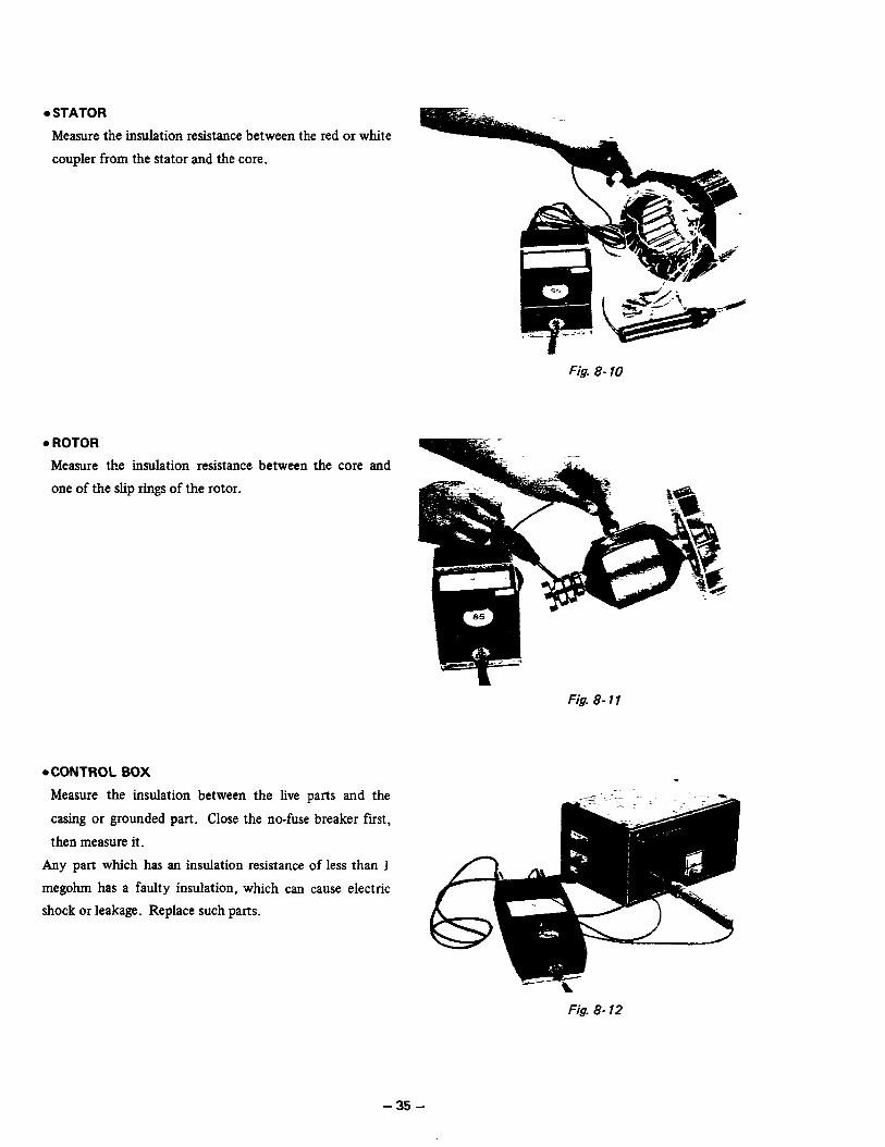
. STATOR
Measure the insulation resistance between the red or white
coupler from the stator and the core.
Fig. 8- 70
. ROTOR
Measure the insulation resistance between the core and
one of the slip rings of the rotor.
Fig. 8- 11
. CONTROL BOX
Measure the insulation between the live parts and the
casing or grounded part. Close the no-fuse breaker first,
then measure it.
Any part which has an insulation resistance of less than 1
megohm has a faulty insulation, which can cause electric
shock or leakage. Replace such parts.
Fig. 8- 12
- 35 -
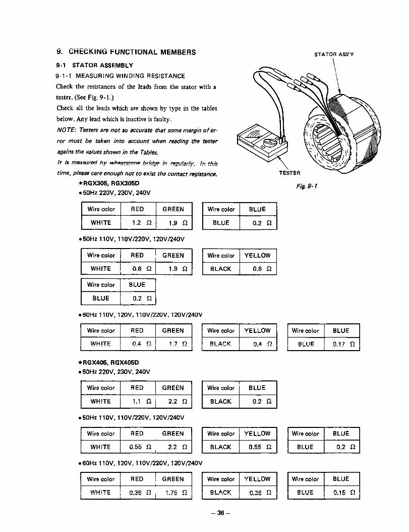
9. CHECKING FUNCTIONAL MEMBERS
9-1 STATOR ASSEMBLY
9-l-l MEASURING WINDING RESISTANCE
Check the resistances of the leads from the stator with a
tester. (See Fig. 9 - 1.)
Check all the leads which are shown by type in the tables
below. Any lead which is inactive is faulty.
NOTE: Testers are not so accurate that some margin of er-
ror must be taken into account when reading the tester
agains the values shown in the Tables.
lt is measured by wheatstone bridge in regularly. ln this
time, please care enough not to exist the contact registance.
STATOR ASS’Y
\ \
*RGX305, RGX305D Fig 9- 1 l 50Hz 220V. 23QV, 24QV
l 50Hz 11 OV, 11 OVf22QV. 12OVf24QV
l 60Hz 1 lOV, 12OV, 1 lOV/22OV, 12OVI24OV
*RGX405, RGX405D
l 50Hz 22OV. 23QV. 24QV
.50Hz 1 IQV, 1 lQVf22OV. 12QVl24OV
1 :h;or 1 ,“I,, ““,::I IWii~;~Y~l-:““,l
l 60Hz 11 OV, 12OV. 11 QVi22QV, 12OVl24OV
I Wire color 1 BLUE 1
BLUE 0.2 52
- 36 -
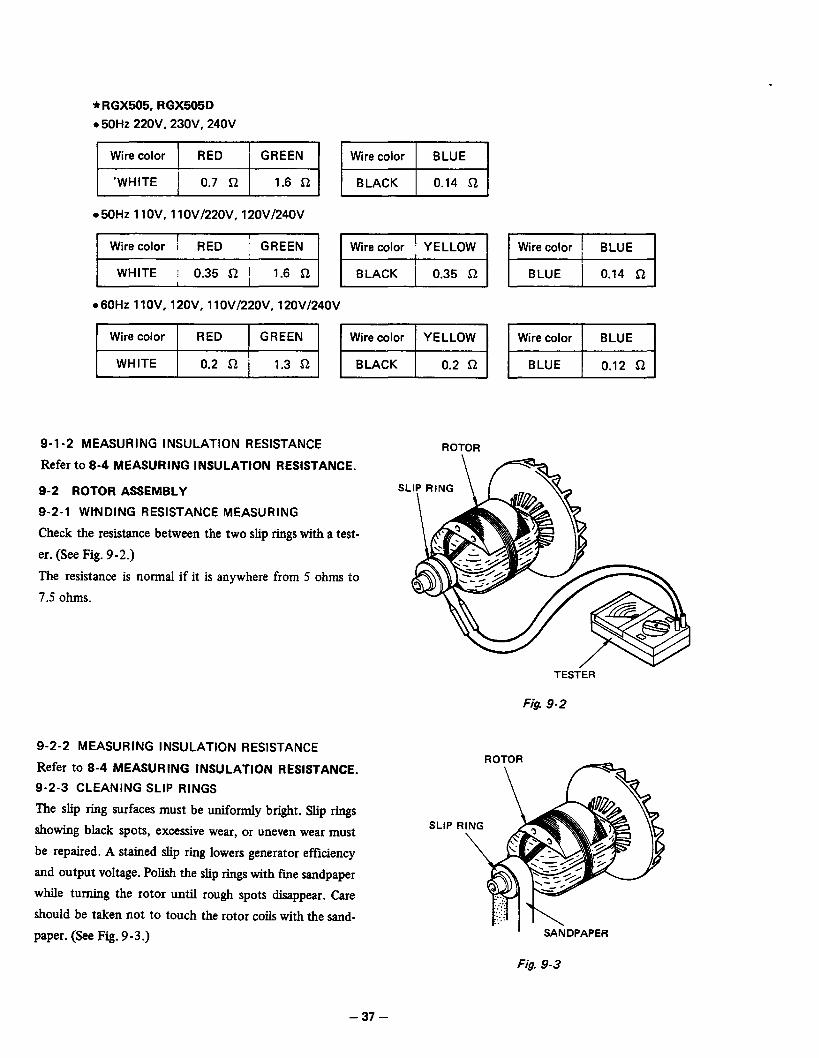
*RGX505, RGX505D
l 50Hz 22OV. 23OV, 240V
yzJG-Jq ml
l 50H.z 1 lOV, llOVI22OV. 12OVl24OV
l 60Hz 11OV. 12OV, llOVi22OV. 12OVi24OV
1 Wire color i BLUE 1
I BLUE ] 0.14 52 1
9-l-2 MEASURING INSULATION RESISTANCE
Refer to 8-4 MEASURING INSULATION RESISTANCE.
ROTOR
9-2 ROTOR ASSEMBLY
9-2-l WWDING RESISTANCE MEASURING
Check the resistance between the two slip rings with a test-
er. (See Fig. 9-2.)
The resistance is normal if it is anywhere from 5 ohms to
7.5 ohms.
TESTER
Fig. 9-2
9-2-2 MEASURING INSULATION RESISTANCE
Refer to 8-4 MEASURING INSULATION RESISTANCE.
9-2-3 CLEANING SLIP RINGS
The slip ring surfaces must be uniformly bright. Slip rings
showing black spots, excessive wear, or uneven wear must
be repaired. A stained slip ring lowers generator efficiency
and output voltage. Polish the slip rings with fine sandpaper
while turning the rotor until rough spots disappear. Care
should be taken not to touch the rotor coils with the sand-
paper. (See Fig. 9-3.) SANDPAPER
Fig. 9-3
- 37 -
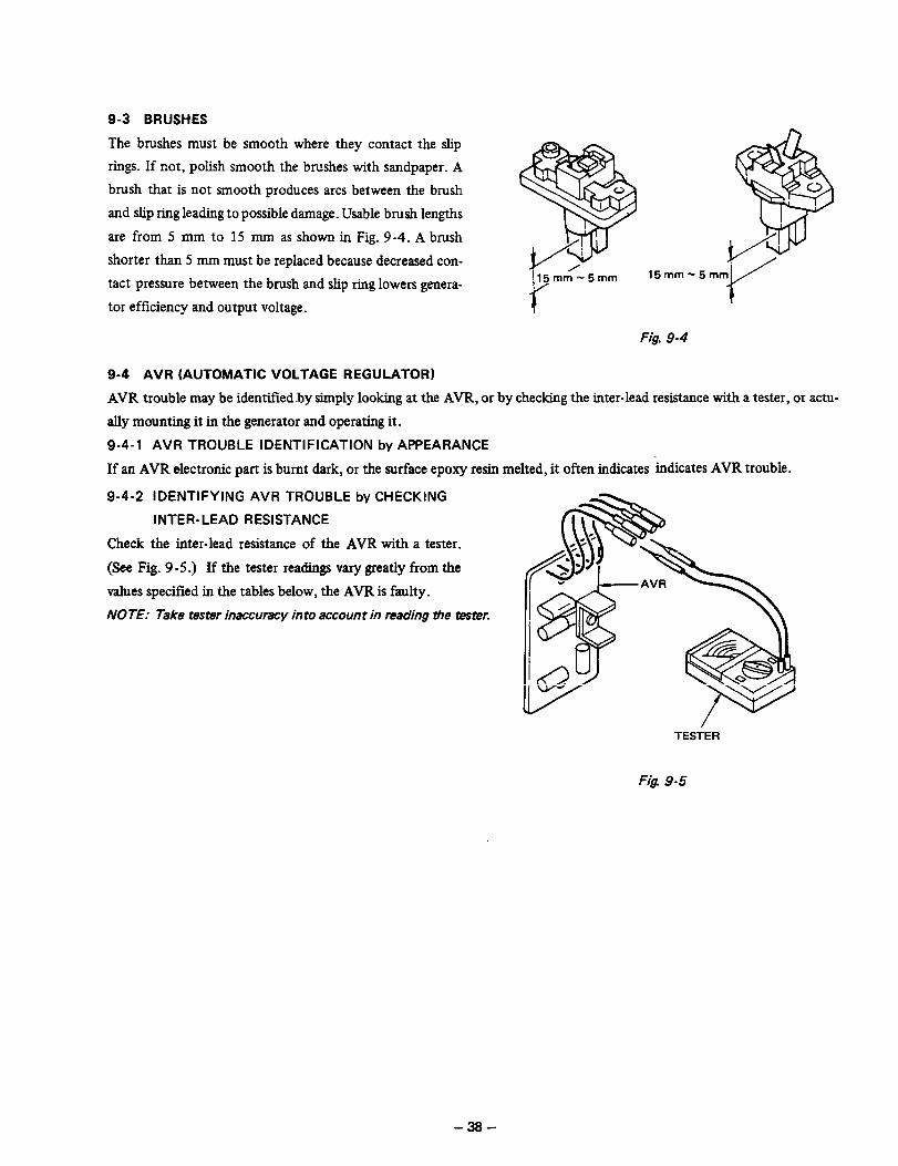
9-3 BRUSHES
The brushes must be smooth where they contact the slip
rings. If not, polish smooth the brushes with sandpaper. A
brush that is not smooth produces arcs between the brush
and slip ring leading to possible damage. Usable brush lengths
are from 5 mm to 15 mm as shown in Fig. 9 -4. A brush
shorter than 5 mm must be replaced because decreased con-
tact pressure between the brush and slip ring lowers genera-
tor efficiency and output voltage.
!15mm-5mm 15mm-5m
r
Fig. 9-4
9-4 AVR (AUTOMATIC VOLTAGE REGULATOR)
AVR trouble may be identified.by simply looking at the AVR, or by checking the inter-lead resistance with a tester, or actu-
ally mounting it ln the generator and operating it.
9-4-l AVR TROUBLE IDENTIFICATION by APPEARANCE
If an AVR electronic part is burnt dark, or the surface epoxy resin melted, it often indicates indicates AVR trouble.
9-4-2 IDENTIFYING AVR TROUBLE by CHECKING
INTER-LEAD RESISTANCE
Check the inter-lead resistance of the AVR with a tester.
(See Fig. 9 - 5 .) If the tester readings vary greatly from the
values specified in the tables below, the AVR is faulty.
NOTE: Take tester inaccuracy in to account in reading tie tester.
TESiER
Fig 9-5
-38-

Tester polarity Yellow Red White j Green Brown
!
I m
I
i7OOK-lMi2 One wire: 052 ’
72K - 120KQ 65K - 1OKR I
Yellow
- Another: QO
One wire: Ost 00 409K - 500KR 72K - 120KS2 65K - 1 OKR
, Another: 00
Red - - Do 400K - 500KC! / 250K - 300KS2
- - 1 130K - 140KSI 00 220K - 250KR
White I
Green i I
Brown j I
- ’ 250K-3OOKSZ ’ - m 1 45K-5OKR
- i 130K- 140Kfi ; - m j 45K- 50KS2
- ! 6OOK-1Mfl i 70K-1lOKR - ! 7K-9.5Kfi
- 1 400K - 5OOKCZ 70K-1lOKn - ’ 6.5K - 8.5KQ
- i 400K - 5OOKS1 40K - 46KR m -
- 250K - 3OOKSZ 40K - 46KS2 00 -
*Upper rows are for the 220,230,24OV specifications; lower rows for the 110,120V specifications and the dual voltage type.
Table 9- 1
MODEL RGX405. RGX465D. RGX505. RGX565D
Tester polarity Yellow Red White Green Brown
Yellow
Red
White
Green
Brown
One wire: OS2 300K - 500KS2
lead resistance 00 1 OKC! - 70KQ
Another: = existence
150K - 25OKfi lOKR- 70KR 1 One wire: OR lead resistance
00 Another: 00 existence
00 j 220K-25OKR = 3OOKR
00 - ; llOK-125KS2 : m ! 15OKa
00 220K-250Ka 1 - 00 / lead resistance 1
00 , llOK-125Kn I* - 00 ’ existence
00 i 330K - 500KSZ I 10K - 70Ka f lead resistance
00 j 150K-256KS2 j IOK-7OKQ 8 existence
00 300K - 5OOKS2 i 10K - 40KS2 m -
00 150K - 25OKR 10K - 40KQ 00 -
*Upper rows are for the 220, 230,240V specifications; lower rows for the 110, 12OV specifications and the dual voltage type.
*Lead resistance existence does not change so big in the amplitude degree of the hand when change the range of the tester.
Table 9-2
9-4-3 IDENTIFYING AVR TROUBLE by MOUNTING AVR in THE GENERATOR and OPERATING AVR
SCR or transistor damage cannot be detected by simply looking at the AVR or checking the lead resistances. Check it by
mounting the suspectedly faulty AVR in a normal generator, or mount a normal AVR in a generator which fails to generate
voltage. -39-

9-5 FUSE HOLDER and NO-FUSE HOLDER
9-5-l FUSE HOLDER
Only the LG301 and LG301D have a no-fuse breaker.
Push the power switch off and check continuity. If no cur-
rent flows, it is normal. Then push the power switch on and
check continuity again. If current flows, it is normal.
If the breaker is a two-pole type, the two pairs of terminals
must carry current.
Fig. 9-6
9-5-2 NO-FUSE BREAKER
Check that a fuse is in the fuse holder and check its conti-
nuity with a tester. (See Fig. 9-7.) If it carries current, it is
normal.
FUSE HOLDER
If there is no current, take the fuse out and check it for
continuity. If the fuse carries current, the fuse holder is
faulty. If the fuse carries no current, replace it with a fuse
of the correct capacity, and check the fuse holder again for
continuity.
Fuse capacity is 10A. Fig, 9-7
-40-

9-6 RECEPTACLE and AC PLUG
Check the current-carrying parts of the receptacles and AC plugs and their leads and plastic parts for bums.
9-7 VOLTMETERS
Apply AC voltage to a terminal and check if the voltmeter
reads normal.
9-8 DIODE STACK ASSEMBLY
-- + e- I-
Fig. 9-9
VOLTMETER
Fig. 9-8
Fig. 9-10
The internal circuitry of the diode stack assembly is as
shown in Fig. 9-9. Check inter-terminal continuity with a
tester as shown in Fig. 9-10 to see that the results are as
shown in Table 9 -8.
I TERMINAL, CURRENT ; TERMINAL
NOTE:
A --4-c B Current flows from A (+I to B 1-J.
1-1 C - D Current does not flow from C PI to D l-1.
‘-I-!-
- Check both terminals
Table 9- 8
-41-
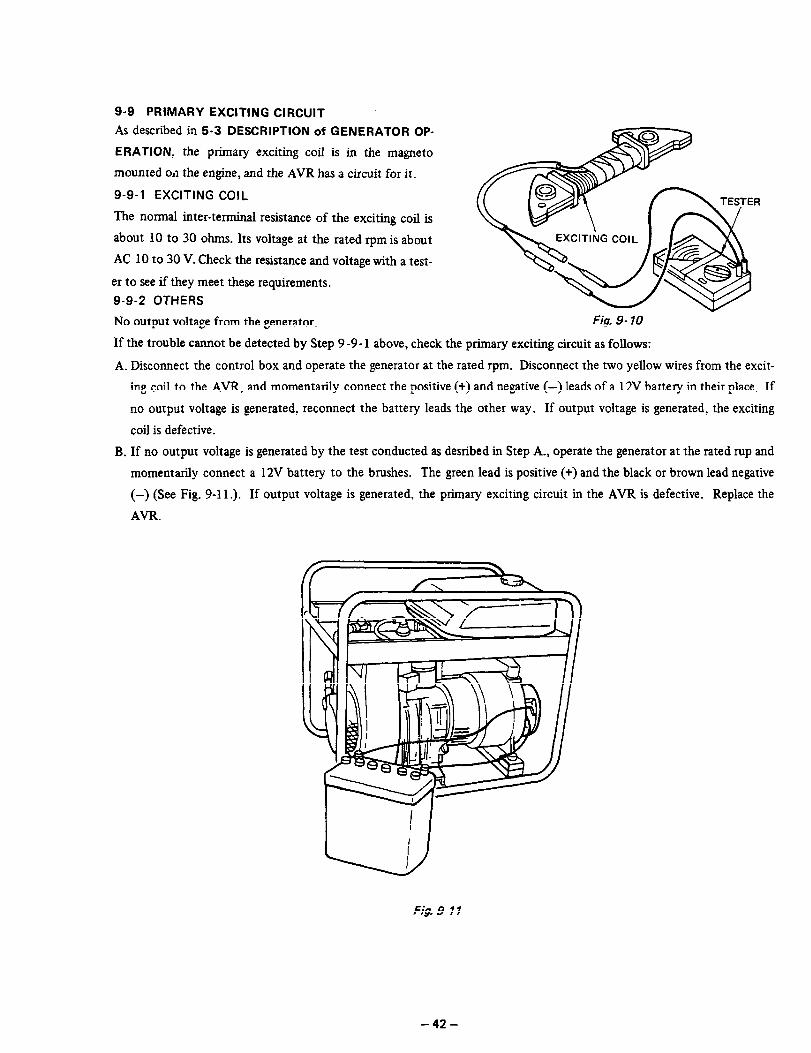
9-9 PRIMARY EXCITING CIRCUIT
As described in 5-3 DESCRIPTION of GENERATOR OP-
ERATION, the primary exciting coil is in the magneto
mounted 0~1 the engine, and the AVR has a circuit for it.
9-9-l EXCITING COIL
The normal inter-terminal resistance of the exciting coil is
about 10 to 30 ohms. Its voltage at the rated rpm is about
AC 10 to 30 V. Check the resistance and voltage with a test-
er to see if they meet these requirements.
9-9-2 OTHERS
No output voltage from the generator. Fig. 9- 10
If the trouble cannot be detected by Step 9-9- 1 above, check the primary exciting circuit as follows:
A. Disconnect the control box and operate the generator at the rated rpm. Disconnect the two yellow wires from the excit-
B.
ing coil to the AVR, and momentarily connect the positive (+) and negative (-) leads of a 12V battery in their place. If
no output voltage is generated, reconnect the battery leads the other way. If output voltage is generated, the exciting
coil is defective.
If no output voltage is generated by the test conducted as desribed in Step A., operate the generator at the rated rup and
momentarily connect a 12V battery to the brushes. The green lead is positive (+) and the black or brown lead negative
(-) (See Fig. g-11.). If output voltage is generated, the primary exciting circuit in the AVR is defective. Replace the
AVR.
Fig. 9- 11
-42-
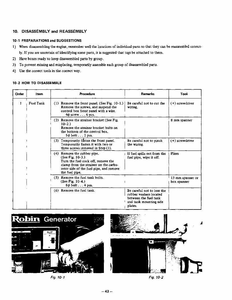
10. DISASSEMBLY and REASSEMBLY
10-I PREPARATIONS and SUGGESTIONS
1) Wren disassembling the engine, remember well the locations of individual parts so that they can be reassembled correct-
ly. If you are uncertain of identifying some parts, it is suggested that tags be attached to them.
2) Have boxes ready to keep disassembled parts by group.
3) To prevent missing and misplacing, temporarily assemble each group of disassembled parts.
4) Use the correct tools in the correct way.
10-2 HOW TO DISASSEMBLE
Order 1 Item Procedure I Remarks I
Tool
1 , Fuel Tank ( 1) Remove the front panel. (See Fig. lo- 1.) Be careful not to cut the 1 (+) screwdriver
! Remove the screws, and suspend the wiling.
i control box front panel with a wire. I
4$ screw . . . 6 PCS.
I (2) Remove the strainer bracket (See Fig. I i ’ 8 mm spanner
I 10-2.) Remove the strainer bracket bolts on the bottom of the control box.
54 bolt . _ . 2 PCS. I
(3) Temporarily f&ten the front panel. 1 Be careful not to pinch (+) screwdriver Temporarily fasten it with two or the wiring. three screws removed in Step (1). :
(4) Remove the rubber pipe. i If fuel spills out from the ’ Rliers (See Fig. 10-3.) fuel pipe, wipe it off. Turn the fuel cock off, remove the clamp from the strainer on the carbu- retor side of the fuel pipe, and remove
I the fuel pipe. I
[ (5) Remove the fuel tank bolts. (See Fig. 10-4.)
89 bolt. . . 4 PCS. (6) Remove the fuel tank.
I
13 mm spanner or I 1 box spanner
I Be careful not to lose the [ rubber washers located * between the fuel tank
I and tank mounting side i plates.
Fig. lo- 1 Fig. 10-2
-43-

Fig. 10-3 Fig. 10-4
Order 1 I
i Item Procedure Remarks Tool
2 Control Box (1) Remove the connector and coupler. The connector and bush- Remove the connector and coupler ing are so designed as to I
that are connect to the rear of the
I
lock, so push and pull control box. out as shown in Fig. lo- 5.
I I
I I
(1)
Fig. 10-5
(2) Remove the control box bolts and 1 Be careful not to drop the ’ 10 mm spanner the control box. the control box. Remove the bolts from the frame and box stay.
I
Fig. 10-6
-44-

Order
3
Item
Frame
Procedure Remarks I
TOOi
(1) Remove the box stay. , It is not necessary to re- 10 mm spanner 69 bolt. . . 2 PCS. move the air guide.
(2) Remove the side plates, front and rear.
(3) Remove the generator mounting nuts.
Black special bolts are used.
10 mm spanner or box spanner
13 mm spanner
I I /
RGX305, RGX305D: Remove the \ nuts that fasten the engine and rubber ( mount and the nuts that fasten the generator and rubber mount. I
89 nut . . .4 PCS. I
I I I
RGX405: RGX405D, RGX505, RGX / The bolts are welded to 505D : Remove the nuts that fasten the engine base. the engine to the engine base, and the nuts that fasten the rubber mount the generator. (See Fig. 1 O-7.) - ,
I ag nut . . .6 PCS. ! I I
(4) Remove the generator. Be careful of the genera- 1 (See Fig. 10-8.) ’ tor balance. Lift the generator with a chain block, j and remove the frame. I
(5) Remove the rubber mount. I Rubber mount is fastened i 13 mm spanner or
RGX405, RGX405D, RGX505, RGX ’ with the nuts welded to box spanner ! 505D: Remove the nuts that fasten the bottom of the frame.
/ :
I the engine base and rubber mount. Twist the rubber mount and take it \ off. i
Fig. 10-7
-45-
Fig. 10-8

Order 1 Item Procedure Remarks Tool I I
4 Brush holder (1) Remove the brush cover. I / (+) screwdriver
I I Remove the brush cover in back of the 1 rear cover.
40 screw. . . 2 pcs. I 1 I
, (2) Remove the brush holders. Be sure to remove the 1
I I (See Fig. 10-9.)
I
/ brush holders first be- I Disconnect the terminals wired to the i brushes before removing the brush
1 cause if the rear cover is removed from the gen- 1
holders. erator without removing 1 I
1
50 screw _ . . 2 pcs. ! the brush holders the I i brushes will break. ’ I
5 1 Rear cover I
i (1) Loosen the cover bolts and remove them.
I
I
* RGX305, RGX305D 10 mm spanner or 6~ bolt . . . 3 PCS. i box spanner
* RGX405, RGX405D, RGX505 RGX505D:
i 13 mm spanner or a box spanner
89 bolt . . . 4 PCS. I
!
(2) Remove the stator cover. Turn up the stator cover edge and
/ (-1 screwdriver
remove the stator cover. I
(3) Remove the rear cover. The type that uses a con-
I (See Fig. lo- 10.) nectar does not permit Lightly tap the rear cover with a complete separation of
I plastic hammer, and remove it. the stator and rear cover *RGX505- llOV, l?OV, RGX505D: because the connector
1 Pull out the wire from the rear cannot be pulled out of ! cover. the rear cover or gram- !
I met. In this case, simply
I
remove the rear cover from the bearing.
Fig. 10-9 Fig. lo-10
-46-

Order
6
T t I I
I Item I Procedure
! I
Stator ! (1) Remove the stator. ! Full out the stator from the front cover
by lightly tapping the outside of the core with a plastic hammer. (See Fig. 10 11.) If the stator does not come out, insert a screwdrive between the front cover and stator, and twist it. (See Fig.
I 10-12.)
i (2) Separate the stator and rear cover. Separate the connector and wire. Rush the terminal locks in the con- nector with a pm having a needle-like sharp point, and remove the terminals, (See Fig. lo- 13.)
f
1 L I t
sever hammer the wind- ings and leads. Be careful not to peel the stator steel sheets.
It is not necessary to separate the stator and rear cover except when re- placing the stator, rear cover, or diode stack.
PUSH
Fig. 10-13
Tool
Plastic hammer or (-) screwdriver
Fig. 10-l 1 Fig. lo-12
-47-
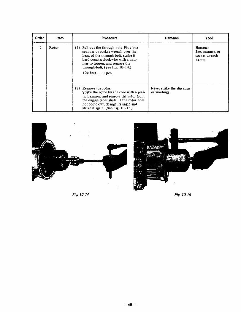
Order item , Procedure Remarks Tool
7 Rotor (1) Pull out the through-bolt. Fit a box Hammer spanner or socket wrench over the Box spanner, or head of the through-bolt, strike it i socket wrench hard counterclockwise with a ham- 14mm mer to loosen, and remove the through-bolt. (See Fig. 10-14.)
1Og bolt . . . 1 pee.
(2) Remove the rotor. Never strike the slip rings Strike the rotor by the core with a plas- or windings. tic hammer, and remove the rotor from the engine taper shaft. If the rotor does not come out, change its angle and
! strike it again. (See Fig. lo- 15.)
Fig. 10-14 Fig. lo-15
- 48 -
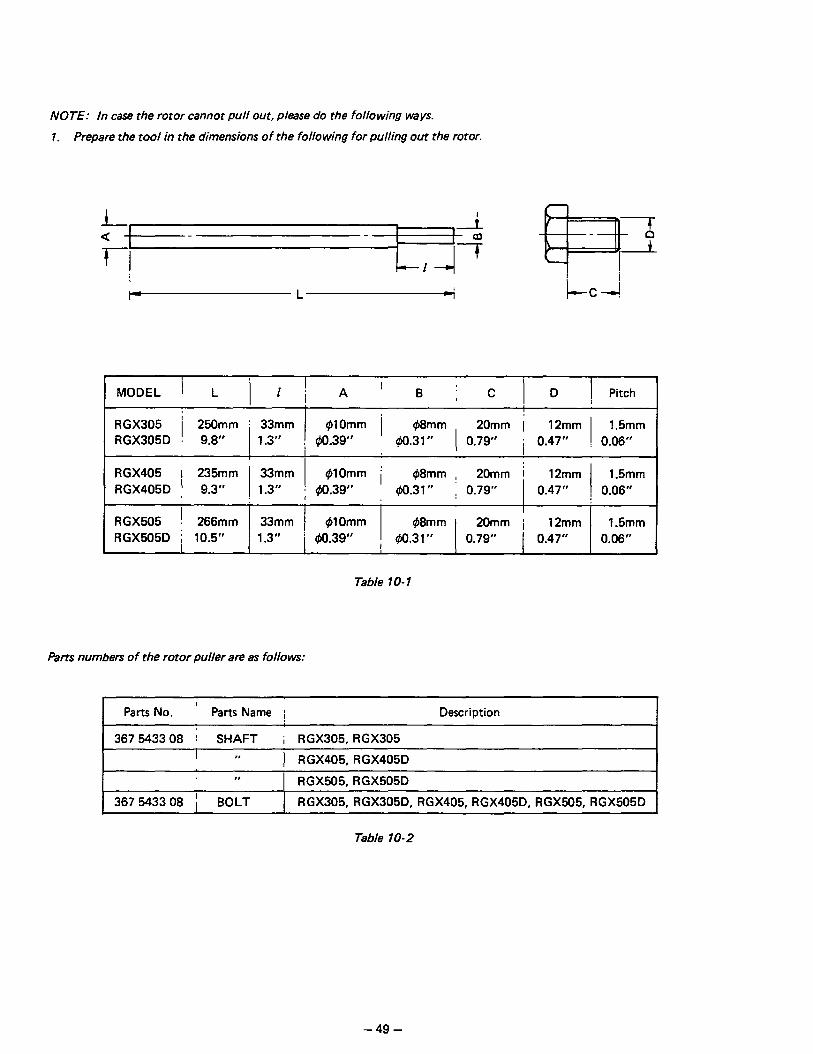
NOTE: In case the rotor cannot pull out, please do the following ways.
1. Prepare the tool in the dimensions of the following for pulling out the rotor.
L, a ,
T!
-i ‘T
-1 -I
MODEL 1 L 11) A’B jC1D ! Pitch
RGX305 / 250mm : 33mm I
@lOmm / @mm , 20mm i 12mm 1.5mm RGX305D : 9.8” 1.3” ; $0.39” G50.31” ( 0.79” i 0.47” : 0.06”
RGX405 1 235mm ’ 33mm f$lOmm / @mm , 20mm / 12mm 1.5mm
RGX405D , 9.3” : 1.3” j 40.39” ’ (bO.31” ; 0.79” 0.47” ! 0.06”
RGX505 ! 266mm 33mm RGX505D i 10.5” 1.3”
1 @lOmm !
#8mm 20mm i 12mm 1.5mm
i qlo.39” ! #0.31” 0.79” ’ 0.47” I 0.06”
Table 1 O- 1
Parts numbers of the rotor puller are as follows:
I Parts No. ’ Parts Name 1 Description I
I 367 543308 i SHAFT i RGX305, RGX305 I I, 1 RGX405, RGX405D
,I RGX505, RGX505D
367 543308 / BOLT RGX305, RGX305D, RGX405, RGX405D. RGX505, RGX505D
Table 10-2
-49-
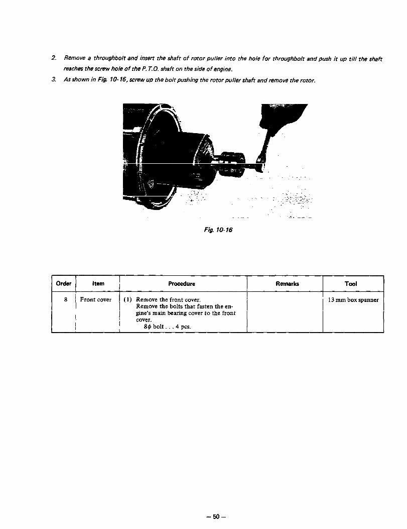
2. Remove a throughbolt and insert the shaft of rotor puller into the hole for throughbolt and push it up till the shaft
reaches the screw hole of the P. T. 0. shaft on the side of engine.
3. As shown in Fig. lo- 16, screw up the bolt pushing the rotor puller shaft and remove the rotor.
Fig. lo-16
1 Order ] Item I Procedure I Remarks I TOOI 1
8 ( Front cover (1) Remove the front cover. I 13 mm box spanner Remove the bolts that fasten the en- I
! gine’s main bearing cover to the front cover.
I [email protected]. 1
- 50 -
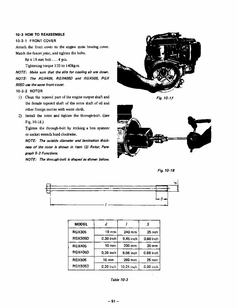
10-3 HOW TO REASSEMBLE
10-3-l FRONT COVER
Attach the front cover to the engine main bearing cover.
Match the faucet joint, and tighten the bolts.
8$xlSmmbolt...4pcs.
Tightening torque 120 to 14Okg-m
NOTE: Make sure that the slits for cooling air an? dew.
NOTE: The RGX405, RGX405D and RGX505 RGX
505D use the same front cover.
10-3-2 ROTOR
1)
2)
Clean the tapered part of the engine output shaft and
the female tapered shaft of the rotor shaft of oil and
other foreign matter with waste cloth.
Install the rotor and tighten the through-bolt. (See
Fig. 10-18.)
Tighten the through-bolt by striking a box spanner
or socket wrench hard clockwise.
NOTE: The outside diameter and lamination thick-
ness of tie rotor is shown in Item 12) Rotor, Para-
graph 5- 2 Functions.
NOTE: The tiro;rgh-bolt is shaped as shown below.
Fig. lo-17
Fig. lo- 18
RGX405 ’ 10 mm 230 mm 25 mm
RGX405D 0.39 inch 9.06 inch 0.98 inch
RGX505 ’ 10mm 260 mm i 25 mm
RGX505D 0.39 inch 10.24 inch 1 0.98 inch
Table 10-3
-51-

10-3-3 STATOR
Install the stator to fit the faucet joint of the front cover.
If it does fit properly, lightly strike the stator core with a plastic hammer as shown in Fig. 10-20.
NOTE: Never strike the winding.
NOTE: Make sure that the mares to tie control box are up and that the wires to the brushes are to the back.
h to CONTROL BOX
toBRUSH HO (GREEN AND
FRONT COVER
o DIODE STACK 0 BLUE WIRES)
ATOR COVER
Fig. lo-19
10-3-4 REAR COVER
1)
2)
3)
Install the diode stack in the rear cover. (See Fig. lo-
21.)
40 x 18 mm screw . . . 1 pc.
Wire the stator to the diode stack.
The diodes are marked as shown in Fig. 10-22.
Connect the two blue wires to the two points marked
0. Connect the orange wire to the point marked 0.
Connect the brown wire to the point marked 0.
Pass all the wires from the stator through the hole
in the top of the rear cover.
Fig. lo-20
Fig. lo-21
I L- DISPLAY
Fig. lo-22
- 52 -
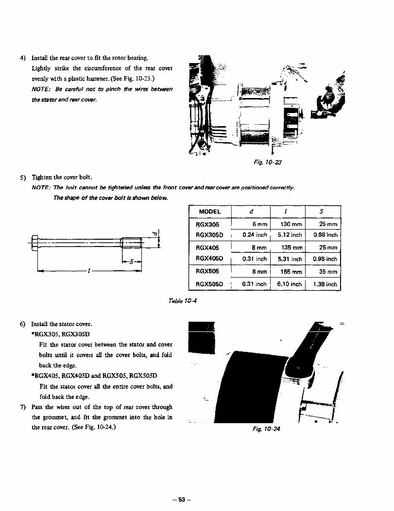
4)
5)
Install the rear cover to fit the rotor bearing.
Lightly strike the circumference of the rear cover
evenly with a plastic hammer. (See Fig. 1 O-23 .)
NOTE: Be careful not to pinch the wires between
the stator and rear cover.
Fig. lo-23
Tighten the cover bolt.
NOTE: The bolt cannot be tightetied unless the front cover and rearcover are positioned correcdy.
The shape of the cover bolt is shown below.
MODEL d I S
RGX305 6mm 130 mm 25 mm I
RGX305D i 0.24 inch j 5.12 inch 0.98 inch
RGX405 1 8mm 135 mm 25 mm
RGX405D - 0.31 inch 5.31 inch : 0.98 inch
RGX505 8mm I 155mm ( 35 mm
RGX505D I 0.31 inch i , 6.10 inch i 1.38 inch
6) Install the stator cover.
+RGX305, RGX305D
Fit the stator cover between the stator and cover
bolts until it covers all the cover bolts, and fold
back the edge.
*RGX405, RGX405D and RGX505, RGX505D
Fit the stator cover all the entire cover bolts, and
fold back the edge.
7) Pass the wires out of the top of rear cover through
the grommet, and fit the grommet into the hole in
the rear cover. (See Fig. 10-24.)
Table 10-4
Fig. lo-24
-53-
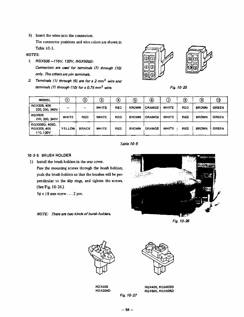
8) Insert the wires into the connectors.
The connector positions and wire colors are shown in
Table 10-3.
NOTES:
1. RGX505 - 1 lOV, 12OV, RGX505D:
Connectors are used for terminals (7) through (101
only. The others are pin terminals
2. Terminals 111 through (61 are for a 2 mm’ wire and
terminals (71 through (10) for a 0, 75mm2 wire. Fig. lo-25
MODEL
RGX305,405 ’
220,230,24OV ! - - 1 ’ RED WHITE BROWN ORANGE WHITE RED BROWN GREEN
RGX505
220,230,24OV WHITE ] RED WHITE RED ’ BROWN ORANGE WHITE , RED BROWN GREEN
I I
RGX305D. 405D. I I
RGX305.405 YELLOW BRACK
I I
WHITE RED BROWN ORANGE WHITE ! RED 1 BROWN GREEN 110,120v I I
Table 10-5
10-3-5 BRUSH HOLDER
1) Install the brush holders in the rear cover.
Pass the mounting screws through the brush holders,
push the brush holders so that the brushes will be per-
pendicular to the slip rings, and tighten the screws.
(See Fig. 10-26.)
54~~18mmscrew...2pcs.
NOTE: mere are two kinds of bursh holders.
Fig. lo-26
RGX305 RGX405, RGX405D RGX305D RGX505, RGX505D
Fig. lo-27
-54-

NOTE: The mounting dirmtion of the brush holders for Models RGX405, RGX405D, RGX505 and RGX 505D
isshown in Fig. lo- 28
GREEN
BROWN
WIRE
WIRE
Fig. lo-28
NOTE: If a brush is installed oblique to the slip ring, the brush holder can break tien the screw is tightened; or the
brush may break when the generator is started.
After installing the brush holders, measure the resistances across the bnrshes and terminals with a tester if they am
from 5 ohms to 7.5 ohms.
If so, the brush holders am corracdy mounted.
2) Attach the connectors to the brush holders.
Connect the green wire to the stator end and the brown wire to the bearing end. (See Fig. 10-28.)
3) Install the brush cover.
RGX305, RGX305D:
4tp x 8 mm screw . . .2 PCS.
RGX405, RGX405D, RGX505, RGX505D:
5~xlOmmscrew...2pcs.
10-3-6 FRAME
1) Attach the rubber mounts to the frame.
Tighten the rubber mounts on the nuts welded to the bottom of the frame.
RGX305, RGX305D.. .4 PCS.
RGX405, RGX405D, RGX505, RGX505D . . .6 pcs.
NOTE: The rubber mounts are so seltxted as to assure optimum vibration depending on model and frequency. Be
sure to use the rubber mounts of the correct parts number. Rubber mounts may appear the same in shape but differ
in hardness. P 1
2) RGX405, RGX405D, RGX505, RGX505D:
Install the engine base. (See Fig. 10-29.)
Benuts.. .4pcs.
Fig. lo-29
- 55 -

3) Install the generator in the frame.
Lift the generator with a chain block, install it in the
frame, and tighten the nuts. (See Fig. 10-30.)
RGX305, RGX305D
RGX405, RGX405D, RGX505, RGX505D
89 nuts . . .6 PCS.
4) Attach the side plates to the frame.
Mount the side plate that reads Robin Generator
Model name to the front, and the blank side plate
to the rear.
NOTE: Use the black bolts for tightening them.
jt$ x 13 mm bolts _ . -8 PCS.
5) Attach the air guide to the box stay.
6) Attach the box stay to the side plates.
6r#~x15mmbolt...2pcs. 10-3-7 CONTROL BOX
1)
2)
Fasten the control box to the frame and box stay.
(See Fig. 10-3 1.)
Wire the primary exciting circuit.
Connect the two yellow wires of the automatic volt-
age regulator in the control box to the exciting coil
wires of the engine, and clamp them to the control
box with cord bushings. (See Fig. 10-32.)
Fig. lo-30
Fig. lo-31
Fig. lo-32
3) Connect the connectors to the control box.
-56-

10-3-8 FUEL TANK
1) Attach the strainer, nut, and banjo to the strainer bracket.
2) Remove the front panel from the control box, and mount the strainer bracket.
5q5~12mmbolt...2pcs.
Mount the front panel again.
3) Mount the fuel tank on the side plates with rubber washers between the side plates and the fuel tank.
84x 18mmbolt...4pcs.
4) Connect the rubber pipes.
First, fit the hose clamps on the rubber pipe, connect the strainer and fuel tank, fasten the rubber pipe with the
hose clamps.
NOTE: Keep the strainer in the off position until the pipe has been connected. (See F&. 10-33.)
\ /FUEL TANK
FUEL GAUGE
RUBBER PIPE 1 . II I
\----- I- HOSE CLAMPS
STRAINER u I
gK,q\ ‘RUBBER PIPE 2
CONTROL BOX ‘FUEL STRAINER
Fig. lo-33
- 57 -

10-4 CONTROL BOX CHECK, DISASSEMBLY, and REASSEMBLY
lo-4- 1 CHECK
Check the wiring by removing the control box from the
frame and taking the top lid off.
10-4-2 DISASSEMBLY
1) Remove the control box top lid, and the front panel
from the control box. (See Fig. 10-34.)
2) Remove the connectors from the control box, and
the wires from the connectors.
NOTE: Push the tenninal locks in #e connectors
with a long, pointed pin to unclock the terminals, and
remove them. (See Fig. 1 O-35.)
3) Remove the automatic voltage regulator.
4) After-disconnecting the wire from each part, remove
the parts.
NOTE: The DC fuse and the full po~rswitch have
their &es soldered to them. Unsolder their wires
first, and then remove them.
10-4-3 REASSEMBLY
Reverse the disassembly procedure.
NOTE: The wires are colored for identification of capacity
and gauge. Be wre to use the same wires as disconnected.
Fig. 70-34
9 PUSH
Fig. 1035
NOTES:
1. RGX505 - 1 lOV, 1aV; RGX505D.
Connectors are used for terminals 171 through (10)
only. 7rhe others are pin terminals
2 Terminals (1) through (61 are for a 2 mm2 wire and
terminals 171 through (1) for a 0.75 mm2 wire.
Fig. lo-36
MODEL @I@~@~@ 0 @ 0 @ @I @
RGX305.405
220.230.24OV BROWN ORANGE 1 WHITE ! RED - 3 - BROWN GREEN WHITE RED
I
RGX505
220,230,24OV i BROWN : ORANGE ! WHITE RED WHITE RED ’ BROWN GREEN WHITE RED
I
RGX305D. 405D I
RGX305.405 ’ BROWN ’ ORANGE WHITE i RED YELLOW i BLACK BROWN GREEN WHITE RED
110,120v I 1
Table 10-6
-58-
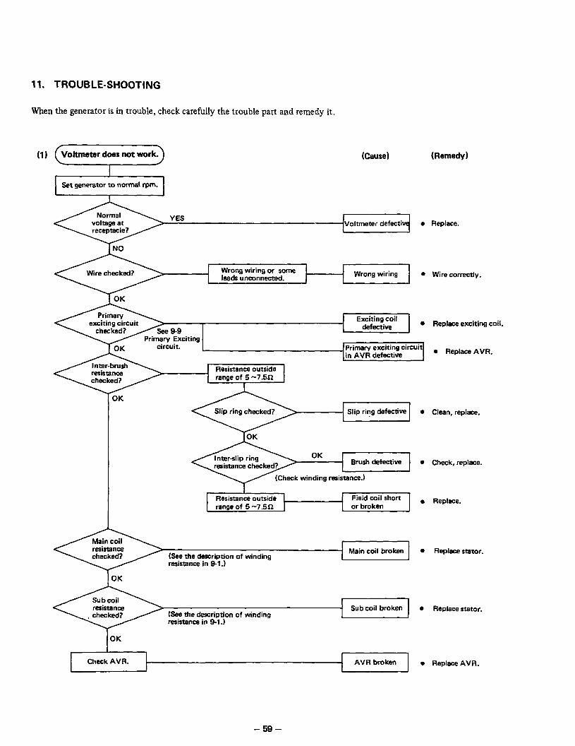
11. TROUBLE-SHOOTING
When the generator is in trouble, check carefully the trouble part and remedy it.
(I) (Cause) (Remedy)
YES
Win? checked? Wrong wiring or some leads unconnected.
1 OK
Resistance outside range of 5 -7.5X2
Slip ring defective
Resistance outside range of 5 -7.5a
Field coil short
Main coil broken
Sub coil broken
resistance in 9-l .I
AVR broken
Replace.
Wire correctly.
Replace exciting coil.
a Replace AVR.
Clean, replace.
Check, replace.
Replace.
Replace stator.
Replace stator.
Replace AVR.
- 59 -

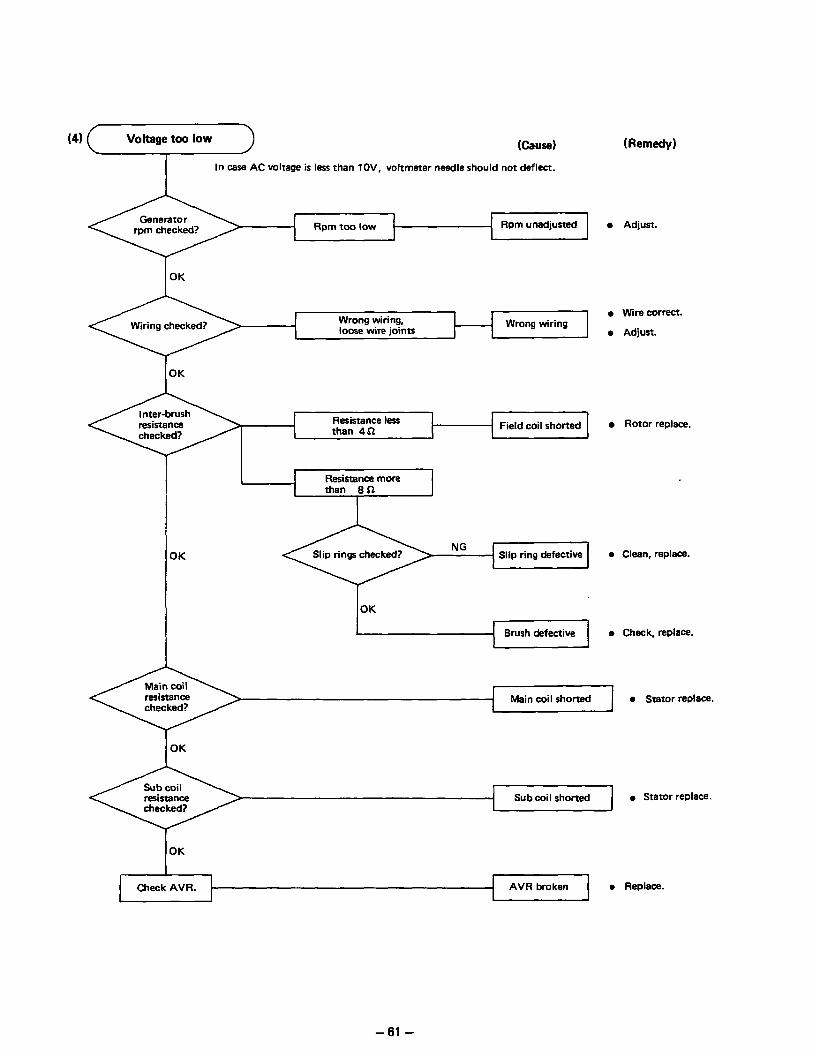
Voltage too low Kau!w)
In case AC voltage is less than lOV, voltmeter needle should not deflect.
Rpm too low Rpm unadjusted
t loose wire joints Wrong wiring
I OK
1 Resistance less than 4a Field coil shorted
NG Slip ring defective
OK
Brush defective
(Remedy)
l Adjust.
l Wire correct.
l Adjust.
0 Rotor replace.
0 Clean, replace.
l Check, replace.
Main coil shorted 0 Stator replace.
OK
Sub coil shorted l Stator replace.
OK
AVR broken l Replace.
- 61 -

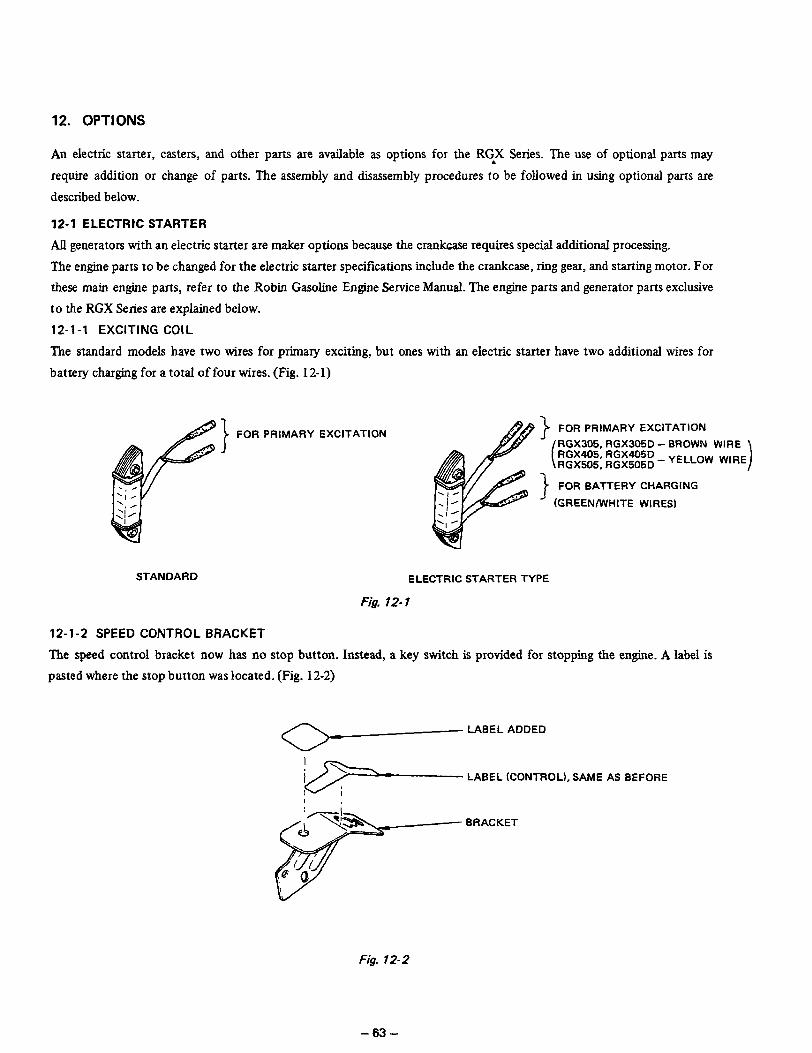
12. OPTIONS
An electric starter, casters, and other parts are available as options for the RG.X Series. The use of optional parts may
require addition or change of parts. The assembly and disassembly procedures to be followed in using optional parts are
described below.
12-l ELECTRIC STARTER
All generators with an electric starter are maker options because the crankcase requires special additional processing.
The engine parts to be changed for the electric starter specifications include the crankcase, ring gear, and starting motor. For
these main engine parts, refer to the Robin Gasoline Engine Service &m.ral. The engine parts and generator parts exclusive
to the RGX Series are explained below.
12-l-l EXCITING COIL
The standard models have two wires for primary exciting, but ones with an electric starter have two additional wires for
battery charging for a total of four wires. (Fig. 12-1)
49) FOR PRIMARY EXCITATION
RGX305, RGX305D - BROWN WIRE RGXa5, RGX405D _ YELLOW RGX505, RGX505D
WIRE
FOR PRIMARY EXCITATION
Le J FOR BATTERY CHARGING
’ (GREEN/WHITE WIRES)
STANDARD ELECTRIC STARTER TYPE
Fig. 12-I
12-l-2 SPEED CONTROL BRACKET
The speed control bracket now has no stop button. Instead, a key switch is provided for stopping the engine. A label is
pasted where the stop button was located. (Fig. 12-2)
- LABEL ADDED ip-
LABEL (CONTROL), SAME AS BEFORE
BRACKET
Fig. 72-2
- 63 -

12-1-3 CONTROL BOX (on ENGINE SIDE)
1) RGX305,305D
A control box such as shown in Fig. 12-3 (1) is installed on the crankcase opposite to the carburetor; and a magnetic
switch and diode rectifier are provided. The cylinder head is provided with a bracket and an ignition coil.
&xlOmm BOLT: 1 PC. SPRING WASHER
LABEL-0 /
COVER COMPL.
, SPRING WASHER I I’
i _ CONTROL BOX
GROMMET
MAGNETIC SWITCH
SPRING WASHER
BOLT: 2 PCS. 5@ NUT: 2 PCS.
TO STARTING MOTOR
Fig. 12-3 (1)
‘ERY (+I
BRACKET
Fig. 12-3 (21
-64-

2) RGX405, RGX405D, RGX505, RGX505D
A control box such as shown in Fig. 12-4 is installed on the crankcase opposite to the carburetor. A magnetic switch
and diode rectifier are installed.
/ DIODE RECTIFIER
B@xlZmrnd B@ x 12 SCREW: 1 PC. : BOLT: 2 PCS. )\
12-l -4 STRAINER BRACKET
\ MAGNETIC SWITCH B@xBmm FLANGE BOLT: 2 PCS. SPRING WASHER
GROMMET
CONTROL BOX COMPL.
TO STARTING MOT0
Fig. 12-4
TO KEY SWITCH
9 TO BAlTERY (+)
RED
The strainer bracket has been changed, and now has a key switch. The key switch is wired to the control box (on the engine
side). (Fig. 12-5)
- 65 -
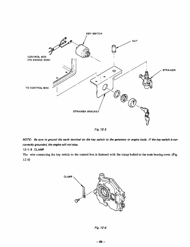
KEY SWITCH
NUT
CONTROL BOX I (TO ENGINE SIDE)
TO CONTROL BOX
/ I STRAINER
STRAINER BRACKEi
Fig. 12-5
AfOE: Be sure to ground the earth terminal on tie key switch to tie generator or engine body. If the key switch is not
correctly grounded, the engine will not stop.
12-l -5 CLAMP
The wire connecting the key switch to the control box is fastened with the clamp bolted to the main bearing cover. (Fig.
12-6)
CLAMP
Fig. 12-6
- 66 -

12-l-6 FRAME (RGX305and RGX305D ONLY)
Only the RGX305 and RGX305D have a frame of different width from before. The frames for the RGX405, RGX405D,
RGX505, and RGX505D remain unchanged.
RGX305,305D STANDARD ELECTRIC START
Fig. 12-7
12-l-7 CIRCUIT DIAGRAMS
BLACK 1-A”
- -3 r-? i SIU ; I I RFn &KEY SWITCH or i(CDI 1 I ; 1
, orKTR)/
i i ! I I I
W - 456 mm (18.0 inch) W - 486 mm (19.1 inch)
BATTERY
STARTING MOTOR CONTROL BOX MAGNETIC
- BROWN
-YELLOW
(ENGINE SIDE) SWITCH Fig. 72-8
- 67 -

12-2 CASTER
1) The caster base is fitted with rubber casters 75 mm in diameter, and the caster base is bolted to the frame.
2) The frame must be drilled to open holes for mounting the caster base.
3) The RGX 305 and RGX305D have a frame 30 mm wider than the standard frame as mentioned in 12-l-6.
4) The RGX405, RGX405D, RGX505, and RGX505D have spacers placed between the frame and caster base.
I \ CASTER BASE
CASTER
Fig. 12-9
-68-
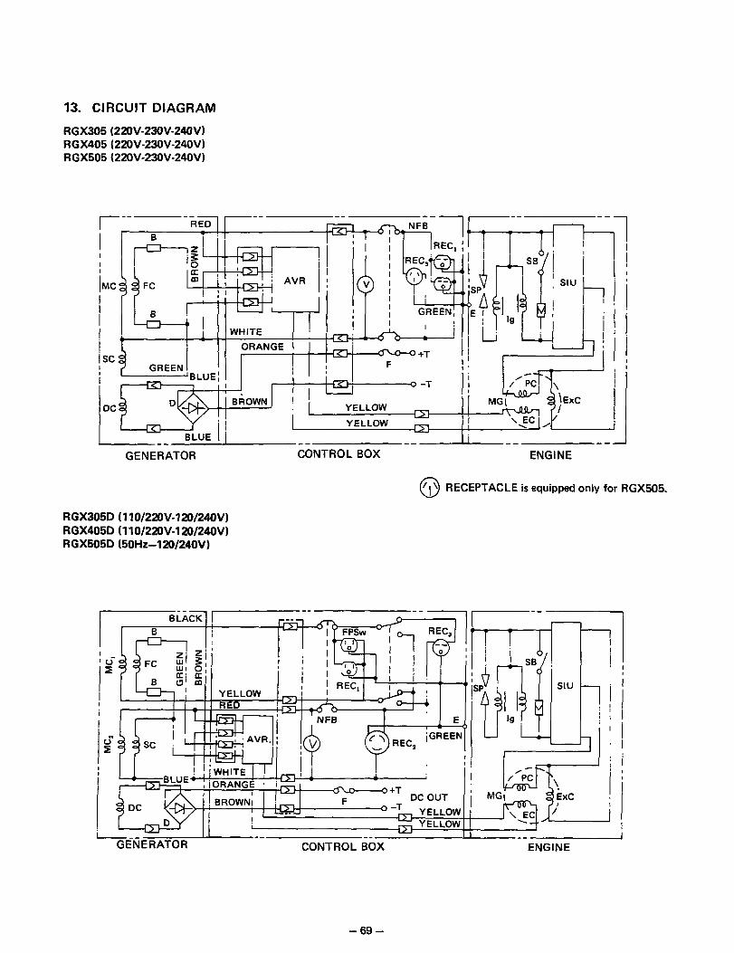
13. CIRCUIT DIAGRAM
RGX305 (220V-23OV-24OV) RGX405 (22OV-23OV-24OV) RGX505 (22OV-23OV-24OV)
pf TFC ‘y--$--p& I
I pc
/,~~--$@jb ; i “=& ~jExc ;Kz == 11 BLUE 1 -- --
I I ‘-‘“J/[ j I --- -- -- J
GENERATOR CONTROL BOX ENGINE
0 ‘11 RECEPTACLE is equipped only for RGX505.
RGX305D (110/22OV-120/24OV) RGX405D (110/22OV-120/24OV3 RGX505D (50Hz-120/240VI
REC,
11 p$$J$~pi SIU
1 ,IutiANGE * i ;
I i”rr\! : mr)r..nIII. ’ 1 I -+T
c
/GREEN
i III : , I : !A ’ ’ j
i
~~ ~~ GENERATOR CONTROL BOX ENGINE
- 69 -

RGX305 (I IOV-I 2OVl RGX405 (IlO-12OV)
7 -- ---If-- I
-- -___
--- j APT
-__ ENGINE ---
REC, pETa ‘0’
REC,
c\ I I I
I i I E
11 *Y - IGREEN
“I” ; ! A+T Im F
IL- o-T
tiLUE1 i u
I
-- --
GENERATOR CONTROL BOX
RGX505D ;;~m&,v,240v
--- BLACK/ I-- --1
I ! i
I iL
--- 7-7-r --
-O’m ;EPSw REC,; 11 ( ] 1 !
i
d ,G \
I
!?!I
EXC
\EC Y
I --- ---- -- -- --A-- -- -
GENERATOR CONTROL BOX ENGINE
MG
- 70 -

RGX505 (lIOV-IZOV)
I i 1~
- Ly I I
GEN&ATOR --
CONTROL BOX --
-- __-.I ENGINE
l SYMBOLS
I Symbols Name of Parts I
I MC AC Winding I
I SC Auxiliary Winding
I DC ! DC Winding I
I FC ’ Field Winding I
1 D / Diode Stack Assy
I F Fuse I
Symbols Name of Parts 4
RECs i AC Output Receptacle
, (22OV/230’.‘/24OV)
IT! DC Output Terminal I
I EC : Exciting Coil (Charge Coil) I
I ExC 1 Excitor Coil I
I PC ! Pulser Coil I
MG Magneto
SB ! Stop Button
I SIU ] Solid State Ignition Unit I
E Earth (Ground) Terminal I
-71-

1 ISSUE EMD-GS0005 1
@FUJI HEAVY INDUSTRIES LTD. INDUSTRIAL PRODUCTS DIV.
2ND Subaru Bldg. 1-1, Choume, Miyahara-cho,
Omiya-shi, Saitama 330-0038, Japan PHONE ; (Omiya 48) 653-5811
FACSIMILE ; (Omiya 48) 653-5691
PRINTED IN JAPAN B303 CE