riotecr/riotecr - ksb casing grey cast iron en-gjl-250 3) with cataphoretic dip coating shaft chrome...
TRANSCRIPT

Riotec Riotec ZEnergy efficiencyclass seetechnical data
Type series booklet1115.52/2-10 Riotecr/Riotecr Z
Circulator Pumpswith Continuously Variable Differential Pressure Control
and I.R. Interface for Remote Control
Fields of ApplicationF Hot-water heating systemsF Heat recovery systems
Fluid PumpedClean water and/or water treated in accordance with the rele-vant regulations, not containing aggressive, abrasive or solidsubstances.Water with commercial antifreeze agents based on glycols(mixture ratio max. 1 : 1) with inhibitors (antirust). If the glycolcontent exceeds 20%, the operating datamust be checkedandverified.Heating water in accordance with VDI 2035.
Operating DataScrew-ended pump Flanged pump 1)
Rp 1 and 1 1/4 DN 32 to 100Q up to 8.6 m3/h, 2.4 l/s up to 90 m3/h, 25.0 l/s 2)H up to 10 m up to 10 mP1 up to 400 W up to 1750 Wp 6 bar; 10 bar on option 6 bar; 10 bar on optiont +20 ˚C to +110 ˚C +20 ˚C to +110 ˚CAmbient temperature max. +40 ˚C1) DN 32 -- DN 65: adapter flanges PN 6/PN 102) if operated in parallel
DesignationRio tec (Z) 50 - 100
Type seriesElectronic controlTwin pumpNominal diameter in mmDischarge head in m x 10 (ex. 100 = 10 m)
DesignRiotec:Maintenance-free wet rotor pump (glandless), flangedor screw-ended, with integrated frequency inverter for continu-ously variable differential pressure control.I.R. (infrared) interface for remote control.LON bus interface can be retrofitted.Riotec Z : Riotec twin pump for stand-by operation (integratedswing check valve) or, on option, additional starting in case ofpeak load (parallel operation).
Control modes:-- ∆p-c for constant differential pressure in the pump-- ∆p-v for variable differential pressure in the pump-- ∆p-T for temperature-governed differential pressure in the
pump
BearingsSpecial plain bearings lubricated by the fluid pumped.
MaterialsVolute casing grey cast iron EN-GJL-250 3)
with cataphoretic dip coatingShaft chrome steel X 40 Cr 13Impeller glass-fibre reinforced polypropyleneBearings special carbon, metal-impregnated
3) to EN 1561 (previously GG-25)
DriveCanned motor, IP 43, thermal class F.
Connection to power supplyRiotec/Riotec Z: 1~230 V, 50 Hz,
interference suppression class B

Riotec
Riotec Z
Riotec/Riotec Z
2
Selection Chart Single Pumps
Selection Chart Twin PumpsThe characteristic curves refer to parallel operation of both pumps.
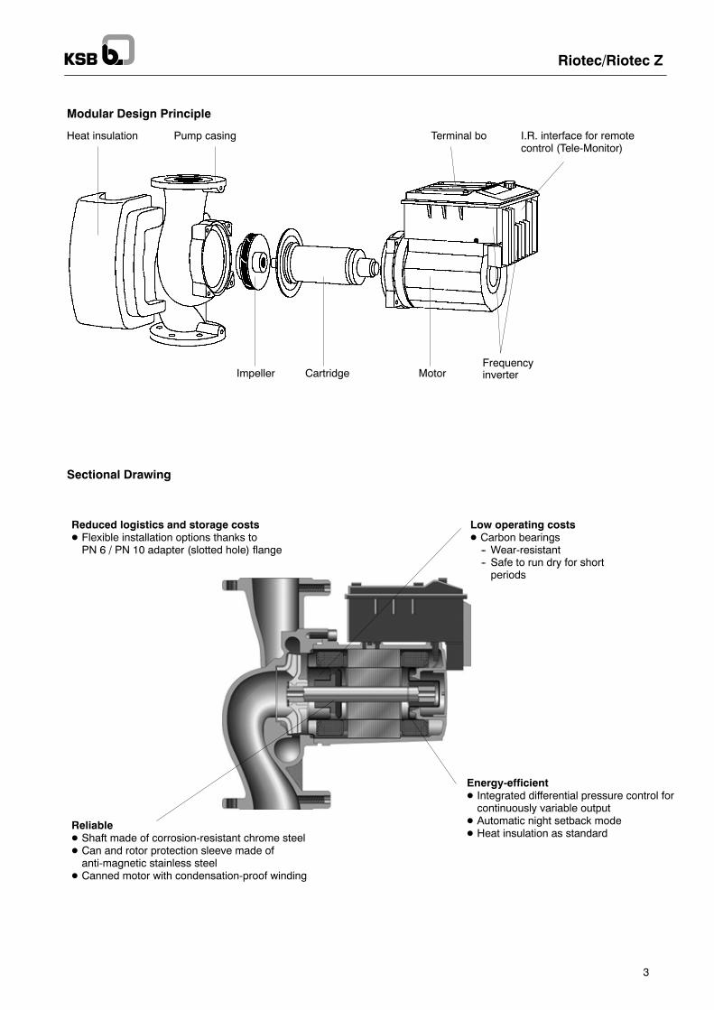
Reduced logistics and storage costsD Flexible installation options thanks toPN 6 / PN 10 adapter (slotted hole) flange
Low operating costsD Carbon bearings-- Wear-resistant-- Safe to run dry for shortperiods
Heat insulation Pump casing
Impeller Cartridge MotorFrequencyinverter
Terminal bo I.R. interface for remotecontrol (Tele-Monitor)
Sectional Drawing
Modular Design Principle
ReliableD Shaft made of corrosion-resistant chrome steelD Can and rotor protection sleeve made ofanti-magnetic stainless steel
D Canned motor with condensation-proof winding
Energy-efficientD Integrated differential pressure control forcontinuously variable output
D Automatic night setback modeD Heat insulation as standard
Riotec/Riotec Z
3

Riotec/Riotec Z
4
= manual operating locked
= bus input occupied
= reduced pump performance
= controlled pump performance
= duty/stand-by mode
= parallel operation
Setting andcontrol knob
= control mode ∆p-c
= control mode ∆p-v
= control mode ∆p-T
= open-loop control mode (n = constant)
= analog input occupied (DDC)
= pump “on”
= pump “off”
= unit, head
= unit, speed
Min. PressureMin. pressure p min at the pump suction nozzle to avoid cavita-tion noise at an ambient temperature of +40 ˚C and a pumpedwater temperature of  max.:
The values are applicable up to 300 m above sea level.For installation at altitudes >300 m, an allowance of+0.01 bar/100m must be added.
t 50 oC 95 oC 110 oC
pminRiotec/Riotec Z bar bar bar
25-7030-7032-7030-10040-4040-7040-10050-6050-7050-10065-10080-100100-100
0.050.050.050.050.050.050.050.050.30.30.30.30.3
0.50.50.50.50.50.50.50.51.01.01.01.01.0
1.11.11.11.11.11.11.11.11.61.61.61.61.6

min. = Night-time operation at minimum speed
Riotec/Riotec Z
5
Single Pump Characteristic Curves

min. = Night-time operation at minimum speed
Riotec/Riotec Z
6
Single Pump Characteristic Curves

min. = Night-time operation at minimum speed
Riotec/Riotec Z
7
Single Pump Characteristic Curves

min. = Night-time operation at minimum speed
Riotec/Riotec Z
8
Single Pump Characteristic Curves

1115:574/2 1115:575/2
min. = Night-time operation at minimum speed
Riotec/Riotec Z
9
Single Pump Characteristic Curves

Night-time operationat minimum speed
Single-pumpoperation
Paralleloperation
P1 curve forsingle-pump operation
Riotec/Riotec Z
10
Twin Pump Characteristic Curves

Night-time operationat minimum speed
Single-pumpoperation
Paralleloperation
P1 curve forsingle-pump operation
Riotec/Riotec Z
11
Twin Pump Characteristic Curves

Night-time operationat minimum speed
Single-pumpoperation
Paralleloperation
P1 curve forsingle-pump operation
Riotec/Riotec Z
12
Twin Pump Characteristic Curves

Night-time operationat minimum speed
Single-pumpoperation
Paralleloperation
P1 curve forsingle-pump operation
Riotec/Riotec Z
13
Twin Pump Characteristic Curves

Motor
Signalling
contacts
protection
Riotec/Riotec Z
14
Technical Data
Riotec DNR
Speed P1 P2 max Ratedt
EEC2)
Max. perm. operating pressureRp current 2)
6 bar 10 bar
1/min W W A kg kg
25-7030-7030-10040-4040-10050-6050-7050-10065-10080-100100-100
11 1/41 1/440405050506580100
1000 -- 28001000 -- 2800900 -- 28001250 -- 2700850 -- 28501000 -- 2800850 -- 2850850 -- 2850850 -- 2850850 -- 2850850 -- 2850
30 -- 20030 -- 20045 -- 40060 -- 20025 -- 62570 -- 39025 -- 62530 -- 93035 -- 98060 --165060 --1650
90901809035018035045057011001100
FFFFFFFFFFF
SSMSSMSSMSSMSSMSSMSSMSSMSSMSSMSSM
0.2 -- 0.90.2 -- 0.90.25 -- 1.80.3 -- 0.90.18 -- 2.750.35 -- 1.70.18 -- 2.810.28 -- 4.10.27 -- 4.310.33 -- 7.20.33 -- 7.2
CCCCBCBBBBB
------------------29 130 36529 130 367
------------------30.531
29 130 35029 130 35129 130 35229 130 52129 130 52229 130 52329 130 52429 130 52529 130 52629 130 36629 130 368
5.55.57.51015.51317.518.52532.533
Riotec Z
Z 32-70Z 40-70Z 40-100Z 50-60Z 50-70Z 50-100Z 65-100Z 80-100
3240405050506580
1000--28001000--2800850--28501000--2800850--2850850--2850850--2850850--2850
30 -- 20070 -- 39025 -- 62570 -- 39025 -- 62530 -- 93035 -- 98060 --1650
901803501803504505701100
FFFFFFFF
SSMSSMSSMSSMSSMSSMSSMSSM
0.2 -- 0.90.35 -- 1.70.18 -- 2.750.35 -- 1.70.18 -- 2.810.28 -- 4.10.27 -- 4.310.33 -- 7.2
CCBCBBBB
--------------29 130 383
--------------59.5
29 130 52729 130 52829 130 52929 130 53029 130 53129 130 53229 130 53329 130 384
1522322433.5364961
1) F = integrated motor protection in the terminal box, SSM = general fault reporting2) Energy efficiency class
Pipe ConnectionFlanged pumps fitted with an adapter flange (oval bolt hole pat-tern) can be connected to PN 6 and PN 16 mating flanges toDIN or DIN EN up to nominal diameters of DN 65. Adapterflanges of this type cannot be connected with other adapterflanges. Use bolts of property class 4.6 or higher for the flangeconnections. Thewashers included in the scope of supplymustbe fitted between the bolt / nut head and the adapter (oval bolthole) flange.
Recommended bolt lengths:
Thread Tightening torque Min. bolt length
DN 32/DN 40 DN 50/DN 65
PN 6 flanged connection
M 12 40 Nm 55 mm 60 mm
PN 10 flanged connection
M 16 95 Nm 60 mm 65 mm
Flange dimensions
Adapterfl
ØkL1/kL2 n x dL1/dL2pflange ØD Ød PN 6 PN 10 PN 6 PN 10
DN 32 140 78 90 100 4 x Ø14 4 x Ø19
DN 40 150 88 100 110 4 x Ø14 4 x Ø19
DN 50 165 102 110 125 4 x Ø14 4 x Ø19
DN 65 185 122 130 145 4 x Ø14 4 x Ø19

Screw unions (accessories)
Pressure gauge connections R 1/8
Simplified top viewof the terminal box
n=numberofholes
nxd
Riotec/Riotec Z
15
Outline Drawing
DNR G
D d k n x dRiotec Rp G l0 a1 a2 b1 b2 b3 l1 PN6 PN16 PN6 PN16 PN6 PN16 PN6 PN16
25-70 1 1 1/2 180 34 56 66 80 123 225
30-70 1 1/4 2 180 34 64 66 88 123 232 Screw-ended pumps
30-100 1 1/4 2 180 40 68 73 93 131 257
p p
40-40 40 -- 220 54 76 83 103 123 237
40-100 40 -- 250 57 88 90 115 160 306
50-60 50 -- 240 39 82 78 112 131 275 Adapter flanges50-70 50 -- 280 63 82 91 116 160 314
Adapter flangesFor flange dimensions refer to page 14.
50-100 50 -- 280 69 91 101 120 160 312
65-100 65 -- 340 79 100 118 134 170 343
80-100 80 -- 360 95 130 135 152 200 371 190 200 128 138 150 160 4 x 18 8 x 18
100-100 100 -- 360 95 130 135 152 200 371 210 220 148 158 170 180 4 x 18 8 x 18
Outline Drawing
DN D d k n x dRiotec Z a b1 l0 l1 k1 k2 m PN6 PN16 PN6 PN16 PN6 PN16 PN6 PN16
32-70 32 39 124 220 232 126 119 115
40-70 40 73 132 250 267 150 143 135
40-100 40 64 165 250 306 178 172 135Ad t fl50-60 50 36 132 280 275 150 143 160 Adapter flangesFor flange dimensions refer to page 14.
50-70 50 62 165 280 314 179 169 160For flange dimensions refer to page 14.
50-100 50 69 165 280 312 198 192 155
65-100 65 80 175 340 343 223 209 185
80-100 80 94 205 360 371 249 231 205 190 200 128 138 150 160 8 x 14 8 x 18

Riotec/Riotec Z
16
Modules and Accessories
Description For type seriesRiotec/Riotec Z
Ident. No. kg
Process control processor(PCP) module (retrofittable)-- PCP interface for connection to the
building management system (BMS)Please note:
-- For twin pump set management2 PCP modules are required
X 01 054 713 0.1
LON module (retrofittable)-- with LON interface
Please note:-- Twin pump set management requires
1 LON and 1 PCP module
X 01 067 694 0.1
Tele-Monitor-- Remote control for Riotec/Riotec Z
with infrared interface (I.R.)-- Start-up and diagnosis instrument/tool-- Extension of pump functions-- Direction of rotation verification
device for all pumps and standardized motors
X 01 054 714 0.4
Technical Data of Tele-Monitor
Type of enclosure IP 43Vibration resistance IEC 68-2-6Operating temperature --10 ˚C to 40 ˚CBearing temperature --20 ˚C to 70 ˚CTransmitting/receiving range max. 10 mDisplay 50 x 50 mm, can be back-lit
Voltage supply 2 mignon alkaline cells(part of the scope of supply)
Operating hours approx. 24 hours when switchedon and back-lit
Permanent buffering EEPROMInterference class EN 50 081-1Interference resistance EN 50 082-2
Functional Description of Tele-Monitor
Communication Menu Automatic connection between pump and Tele-Monitor viainfrared interface (manual coding of the pumps is not required)
Display Menu Display of the pump’s actual data-- Type-- Set value ∆p, actual value ∆p-- Flow rate-- Set speed, actual speed-- Power input-- Mode of operation (∆p-c, ∆p-v, ∆p-T, on/off, ...)-- Fault reporting
Operation Menu Changing mode of operation and set value-- Control mode (∆p-c, ∆p-v, ∆p-T, ...)-- Set value (∆p, speed)-- On/Off
Statistics Menu Analysis of the pump’s load profile-- Histograms of the actual electrical and hydraulic values of
one operating cycle-- Operating hours counter and operating data counter
Service Menu -- Fault diagnosis-- Fault statistics-- Operation check run of the pump-- Operation check run of the monitor-- Operation check run of the connection via PCP interface-- Checking direction of rotation (can be used for all pumps and
standardized motors)
Customization Menu Customization of the Tele-Monitor-- Selecting the dialogue language-- Display contrast-- Automatic cut-out time (time out)-- Personal password-- Basic setting for automatic pump set-up at the push of a button

Riotec/Riotec Z
17
Wiring Diagramfor pump sizes:25-70, 30-70, 30-100, 32-70, 40-40, 40-70 and 50-60
SSM = general fault reporting(volt-free NC contact for 1 A, 230 V)
1~230 V, 50 Hz
Wiring Diagram of PCP Module
DP = interface for twin pump set management
PLR = interface for PCP bus
for pump sizes:40-100, 50-.., 65-.., 80-.. and 100-..
1~230 V, 50 Hz
SSM = general fault reporting(volt-free NC contact for 1 A, 230 V)
Ext.Ein/Aus = external On/Off via volt-free NC contact
+24 V = auxiliary voltage supply
0 -- 10 V = control input for remotespeed adjustment
Wiring Diagram of LON Module
DP = interface for twin pump set management
LON = interface for LON bus
DP
LON

Riotec/Riotec Z
18

Riotec/Riotec Z
19

1115.52/2-10
/1.10.2007
Subjecttotechnicalm
odificationwithoutpriornotice.
Riotec/Riotec Z