river conservation and rehabilitation eah 416 - usmredac.eng.usm.my/eah/document/river conservation...
TRANSCRIPT

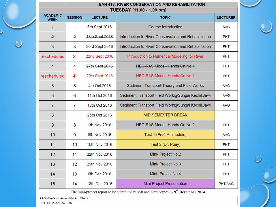
RIVER CONSERVATION AND REHABILITATION
EAH 416PUAY HOW TION
PC LAB AEROSPACE

AFTER COMPLETING THIS COURSE,YOU SHOULD BE ABLE TO
• Write and understand the governing equations for steady flow
• Predict water surface profile (wsp)
• Understand the required boundary conditions to solve for wsp
• Solve numerically for water surface profile by using :
• Spreadsheets
• Programming language : fortran/matlab (or other languages)
• Commercial software : HEC-RAS (or others)

Governing Laws
Conservation of mass
Continuity equation
Conservation of energy
Bernoulli equation
Conservation of momentum
Momentum equation
State of material Equation of state
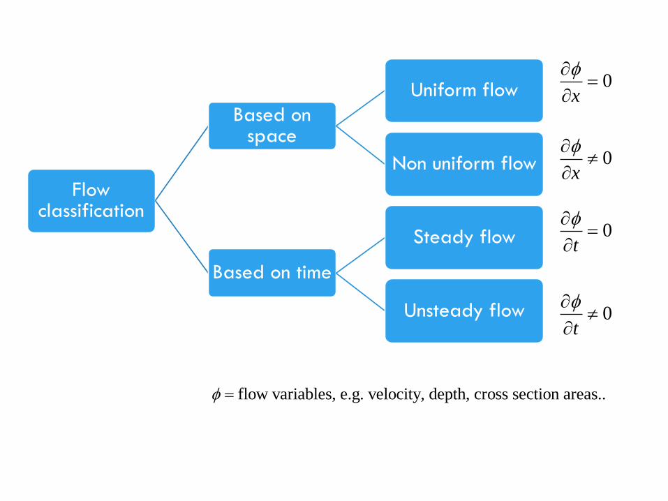
Flow classification
Based on space
Uniform flow
Non uniform flow
Based on time
Steady flow
Unsteady flow
0t
0t
0x
0x
flow variables, e.g. velocity, depth, cross section areas..
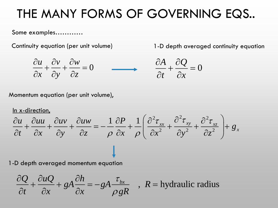
THE MANY FORMS OF GOVERNING EQS..
0u v w
x y z
0
A Q
t x
22 2
2 2 2
1 1 xyxx xzx
u uu uv uw Pg
t x y z x x y z
Continuity equation (per unit volume) 1-D depth averaged continuity equation
Momentum equation (per unit volume),
, hydraulic radiusbxQ uQ hgA gA R
t x x gR
1-D depth averaged momentum equation
Some examples…………
In x-direction,

HOW DO WE CHOOSE THE SUITABLE FORM OF GOV. EQ ?
• The flow direction :
• Mainly in one direction – use 1D equation
• Mainly in two-directions – use 2D equation
• Flow is complex, all directions – use 3D equation
• What phenomena are we interested in?
• Hydraulic jump- at least 2D equation
• Turbulent flow structure – 3D equation
• Wave breaking on surface – 3D equation

• Nature of the flow
• Steady flow : use steady equation
• Unsteady flow : use unsteady equation
• Study purpose and accuracy needed
• To reduce complexity of the solution, assumptions
are made and governing equations are
simplified. Assumptions made must not sacrifice
accuracy and cause lost of important flow
characteristics.
HOW DO WE CHOOSE THE SUITABLE FORM OF GOV. EQ ?
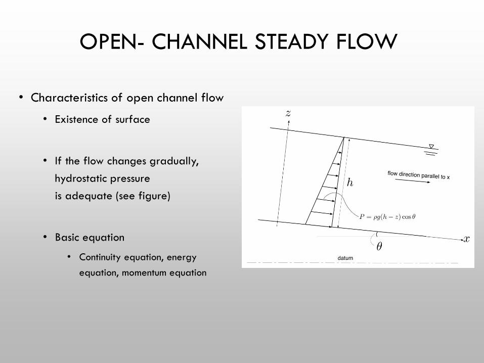
OPEN- CHANNEL STEADY FLOW
• Characteristics of open channel flow
• Existence of surface
• If the flow changes gradually,
hydrostatic pressure
is adequate (see figure)
• Basic equation
• Continuity equation, energy
equation, momentum equation
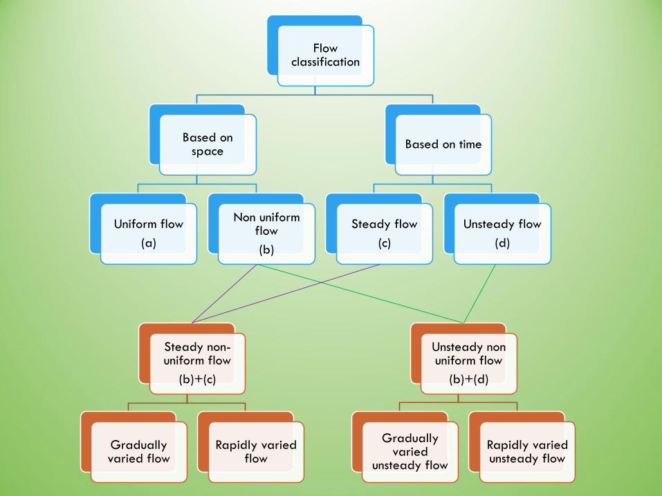
Flow classification
Based on space
Uniform flow
(a)
Non uniform flow
(b)
Based on time
Steady flow
(c)
Unsteady flow
(d)
Steady non-uniform flow
(b)+(c)
Gradually varied flow
Rapidly varied flow
Unsteady non uniform flow
(b)+(d)
Gradually varied
unsteady flow
Rapidly varied unsteady flow
GRADUALLY VARIED FLOW
• DERIVATION OF CONTINUITY AND ENERGY EQUATION
• FLOW SURFACE PROFILE CLASSIFICATION
• UNIFORM FLOW RESISTANCE LAWS
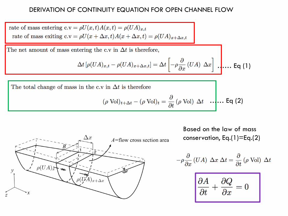
DERIVATION OF CONTINUITY EQUATION FOR OPEN CHANNEL FLOW
…… Eq (1)
…… Eq (2)
Based on the law of mass
conservation, Eq.(1)=Eq.(2)
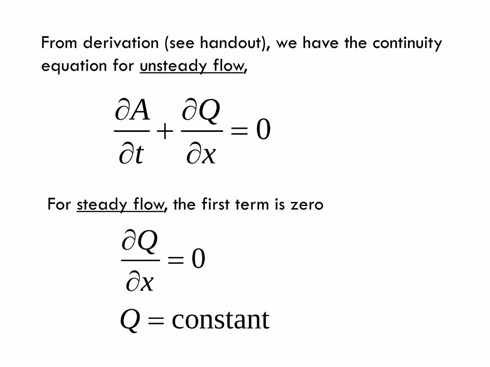
From derivation (see handout), we have the continuity
equation for unsteady flow,
0A Q
t x
For steady flow, the first term is zero
0
constant
Q
x
Q
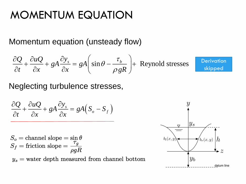
MOMENTUM EQUATION
Momentum equation (unsteady flow)
Neglecting turbulence stresses,
sin Reynold stressess byQ uQgA gA
t x x gR
s
o f
yQ uQgA gA S S
t x x
Derivation
skipped

ENERGY EQUATION
ENERGY AT TWO SECTIONS (EXPRESSED IN HEAD) FOR UNSTEADY FLOW

ENERGY AT TWO SECTIONS (EXPRESSED IN HEAD) FOR STEADY FLOW

By principle of energy conservation,
Rearranging,
Change in total head Friction loss
divide by Dx,
2 2 2
2 2 2f
V V Vz d z dz d d d d h
g g g
2
2f f
Vd z d h S x
g
D
2 2
Specific energy ,
cos2 2
o
o
H
V VH d h
g g
Channel slope o
o
S
dzS
dx
Friction slope f
f
S
SgR
o
o f
dHS S
dx

2 2
Specific energy ,
cos2 2
o
o
H
V VH d h
g g
22
2 22 2
2 2 3
2
3
2
3
2 2
3 3
cos cos2 2
1 2
2
2cos
2
2cos
2
o
o
dH d V dh dh V
dx dx g dx g dx
d d Q d Q dAV Q
dx dx A dx A A dx
Q A A dh
A x h dx
dH dh Q A A dh
dx dx g A x h dx
dh Q A Q A
dx g A h g A x
constant constant
is function of and , therefore
h x
A x h
dA A dx A
dx x dx h
dh A A dh
dx x h dx
rearrange
2 2
3 3
2
3
2
3
cos
cos
o
o f
o f
o f
dHS S
dx
dh Q A Q AS S
dx h xgA gA
Q AS S
xdh gA
dx Q A
hgA
from o
o f
dHS S
dx

Determination of flow profile of steady flow
Case 1 : uniform channel
…. Eq. (3)
2
3
2
3cos
o f
Q AS S
xdh gA
dx Q A
hgA
Where definition is used.o
dzS
dx
If we assume 0 , 1,
Eq.(3) can be transformed into the following form,
fS
For uniform channel . Therefore, 0 and A A
A Bh Bx h

Definition of normal depth, oh
0dh
dx
2
3
Therefore, numerator =0
0o f
Q AS S
xgA
2
3
Definition of critical depth,
Therefore, denominator=0
cos 0
ch
dh
dx
Q A
hgA
Other definition of critical depth,
1) 0 (minimum specific energy, )
2) Froude number=1
c
o
o
h
dHH
dx

Definition of critical slope ic
for a rectangular channel where physical shape and roughness n are
known, for an arbitrary discharge Q, there exists a slope where the
flow is normal flow (dh/dx=0) and the depth is equivalent to critical
depth, this slope is called the “critical slope”
in the case wide rectangular channel , R=h
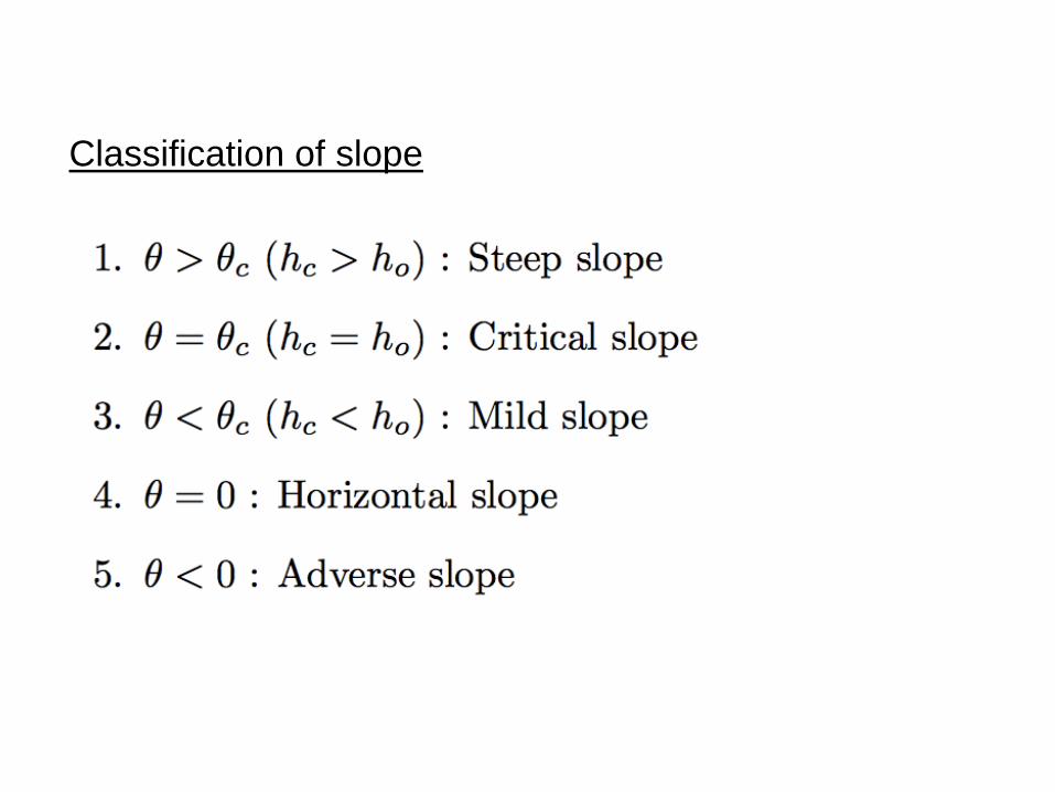
Classification of slope

wide rectangular channel, using Manning’s n
10/3
3
1 /
1 /
o
o
c
h hdhS
dx h h

Steep slope

Mild slope
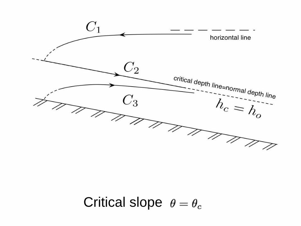
Critical slope


steep slope mild slope

METHOD OF CALCULATION
1) Standard Step Method - all kinds of channel : varying width
(river), fixed width (prismatic
channel)
For river : - the bottom bed of a river is
often uneven, so it is not practical to
measure water depth, h.
So, we measure the total value of z+d
from the datum that we set (here d=h cos
theta). Theta is the angle between the
bed and the datum line
By energy principle
2 2 2
2
2
2 2 2
2
where cos2
f
f f
f
V V Vz d z dz d d d d h
g g g
Vd z d h S x
g
Vd Z S x Z z d z h
g
D
D
2 2
1 2
2 1
1 where
2 2 2f f f f
V VZ Z S x S S S
g g
D
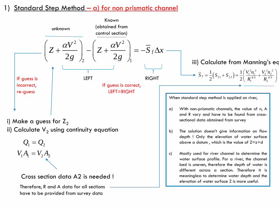
2 2
2 12 2
f
V VZ Z S x
g g
D
Known
(obtained from
control section)
i) Make a guess for Z2
ii) Calculate V2 using continuity equation
iii) Calculate from Manning’s eq.
2 2 2 2
1 1 2 21 2 4/3 4/3
1 2
1 1
2 2f f f
V n V nS S S
R R
1 2
1 1 2 2
Q Q
V A V A
Cross section data A2 is needed !
1) Standard Step Method – a) for non prismatic channel
When standard step method is applied on river,
a) With non-prismatic channels, the value of n, A
and R vary and have to be found from cross-
sectional data obtained from survey
b) The solution doesn’t give information on flow
depth ! Only the elevation of water surface
above a datum , which is the value of Z=z+d
c) Mostly used for river channel to determine the
water surface profile. For a river, the channel
bed is uneven, therefore the depth of water is
different across a section. Therefore it is
meaningless to determine water depth and the
elevation of water surface Z is more useful.
Therefore, R and A data for all sections
have to be provided from survey data
unknown
If guess is
incorrect,
re-guess
If guess is correct,
LEFT=RIGHT
LEFT RIGHT

EXAMPLE 1
A broad crested rectangular weir forms a control point in a river channel. At a distance of 10m upstream the weir, the
rectangular channel has an average bed elevation of 48.895m above ordinance datum (OD), a width of 10 m and the depth
of flow is 1.49m when the discharge is 19m3/s.
Upstream of the control point the width, area and roughness of the channel vary along its length. Cross-sections of the channel
have been surveyed and plotted at 10m intervals upstream the weir. For the water levels shown in column 3 of Table 1, the
appropriate values A, n and R are shown in columns 4,7,8.
Assume energy coefficient = 1.0, and the bed slope is 1 in 400. It is thought that the normal depth in the channel is about
1.3m.
There is some concern that the weir may cause the river to overtop its bank in the 100m length of the channel nearest to the
weir, particularly at chainage 80m where the bank dips to 50.7m OD.
Calculate the elevation of the water surface and determine if this is a problem.

(1) (2) (3) (4) (5) (6) (7) (8) (9) (10) (11)
Chainage
(m)
DL
(m)
Z
(m) OD
A
(m2)
V
(m/s)
H=Z+V2
/2g
n
(s/m1/3)
R
(m)
Sf Sfave H2=H1+
Sfave
*DL
0 (weir)
10 (CP) 10 50.385 15.111 1.257 50.466 0.035 1.144 0.00162 - -
20 10 50.411 16.350 1.162 50.480 0.035 1.158 0.00136 0.00149 50.480
30 10 50.419 15.833 1.200 50.492 0.030 1.149 0.00108 0.00122 50.492
40 10
50 10
60 10
70 10
80 10
90 10
100 10 50.499
Table 1

1) Check discharge
2) Check critical depth
Since the actual depth upstream of the weir is 1.49m, h=1.49m>ho=1.3m >hc=0.72m,
The slope is a mild slope and the water surface profile is of type M1 (backwater curve)
The calculation to obtain the elevation is shown in Table 1.
Calculation for row 2 (chainage 10m)
1) V1=Q/A1=19.00/15.111=1.257 m/s (column 5)
2) H1=Z1+V1^2/(2g)=50.385+1.257^2/(2g) = 50.466 (column 6)
3) Sf = (V1*n1)2/R14/3=(1.257x0.035)2/(1.144)4/3=0.00162 (column 9)
Since chainage 10m is a control point, calculation stop there.
Calculation for row 3 (chainage 20m)
3) Guess the value of Z2, (Z2=50.411)
4) Calculate H (column 6)=50.480, calculate Sf (column 9)
5) Calculate Sfave =1/2(Sf1+Sf2)=1/2(0.00162+0.00136)=0.00149
6) Calculate H2 (column 11) = H1+Sfave*DL=50.466+0.00149*(10)=50.480
7) Compare H2 from Step 6 with H2 from Step 4. If same, then repeat for next chainage.
If not same, then guess Z2 in step 3 and repeat calculation until H2 in Step 6 same with H2 in Step 4.

1) Standard Step Method – b) for prismatic channel
2 2 2
2
2
2 2 2
2
where is called the specific energy2
where is the slope of the bed
Therefo
f
ff
f
f fo o
V V Vz d z dz d d d d h
g g g
Vd z d h S x
g
Vd z H S x H d
g
dH dz dzS S S S
dx dx dx
D
D
2 1
2 1
re,
fo
fo
H H S S x
H H S S x
D
D
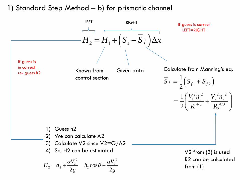
2 1 foH H S S x D
Given data Calculate from Manning’s eq.
2 2
2 22 2 2 cos
2 2
V VH d h
g g
1) Guess h2
2) We can calculate A2
3) Calculate V2 since V2=Q/A2
4) So, H2 can be estimated
Known from
control section
1) Standard Step Method – b) for prismatic channel
1 2
2 2 2 2
1 1 2 2
4/3 4/3
1 2
1
2
1
2
f f fS S S
V n V n
R R
V2 from (3) is used
R2 can be calculated
from (1)
RIGHTLEFT
If guess is
in correct
re- guess h2
If guess is correct
LEFT=RIGHT

PRACTICE 1
• PREDICT THE FLOW PROFILE FOR
STEADY FLOW USING STANDARD
STEP METHOD
hcx
y
h(x)
Control point
A prismatic, rectangular channel is 6m
wide.
The channel has bed slope of 1 in 800
and Manning’s n is 0.017 s m-1/3.
The channel terminates in a vertical drop
so that the flow falls freely into a lower
reservoir. The channel is designed to
carry 35m3/s at normal depth of 2.34m
Assume the flow passes the critical depth
near the drop. Calculate the elevation of
the water surface in the channel using
specific energy head (use standard step
method).
And determine:
a) The distance at which the water
surface is within 10mm of the normal
depth.
Hint : use dx=100m, since theoretically
the water surface approaches the
normal depth at infinity.

PRACTICE 2 The jet emerging from an underflow
vertical sluice gate contract to a vena
contracta just downstream of the gate
where the depth is D=0.85m.
Downstream of the sluice gate where the
flow is unaffected the corresponding
normal depth is 2.60m. The channel has
a uniform rectangular cross-section of
7.00m wide, Manning’s roughness n of
0.030s/m1/3 and bed slope of 1 in
200m. Assuming energy correction
coefficient is 1.00, use the standard step
method to determine the surface water
profile and the location of the hydraulic
jump.
Fr <1.7 1.7 2.0 2.5 3.0 4.0 5.0 7.0 14.0 20.0
Lj Undular
jump
4.0h2 4.4h2 4.8h2 5.3h2 5.8h2 6.0h2 6.2h2 6.0h2 5.5h2
Lj=length of jump
h2=subsequent depth after jump
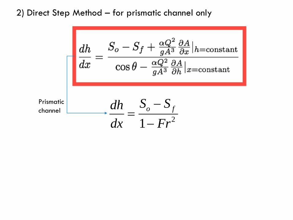
2) Direct Step Method – for prismatic channel only
21
o fS Sdh
dx Fr
Prismatic
channel

2) Direct Step Method – for prismatic channel only
2
2
1
1
o f
ave
o f ave
S Sdh
dx Fr
Frx h
S S
D D
1) Predetermine delta h
A Bh hh
n
D
n= number of
calculation point
between h1*
and h2*
2) Terms here
calculated using h(i)
and h(i+1)( 1) (i)h i h h D
3) Location of h(i+1)
can be determined
x
y
hA
Control point
hB
Known depth (e.g. normal depth)
hi
In direct step method, the distance DL required for the water depth to change by a
fixed amount of Dh are calculated.
This method is preferred by many for prismatic channel since it afford direct solution
without the need to guess values and undertake several iteration

PRACTICE 3
In Practice 1 the 6m wide rectangular channel ended in a vertical drop into a reservoir. An
alternative arrangement is to be investigated in which the channel would end in a ramp or
spillway with a slope of 1:10. Assume that this part of channel is long enough for the flow to
become established at the normal depth before it encounters any backwater from the
reservoir. At the end of the channel the depth will be constant at 4.755m as dictated by the
water surface level in the reservoir. Take Q=35m3/2, energy coefficient as 1 and n=0.017.
Determine the elevation of the water surface profile in the channel.