rjp-120g/t series remote jack packs installation & setup ... · pdf filethe rjp interface...
TRANSCRIPT
RJP-120G/T SeriesRemote Jack Packs
Installation & Setup Guide Warranty
© Copyright 2008, LG Electronics U.S.A., Inc.

2
For Customer Support/Service, please call: 1-888-865-3026www.lgcommercial.com
206-4053
The exclamation point within an equilateral triangle is intended to alert the user to the presenceof important operating and maintenance (servicing) instructions in the literature accompanyingthe appliance.
CAUTION: TO REDUCE THE RISK OF ELECTRIC SHOCK - - USE ONLY INDOORS
ATTENTION:RISQUE DE CHOCS ÉLECTRIQUE - - POUR INSTALLATION À L¡¯INTÉRIEUR SEULEMENT
WARNING:TO PREVENT FIRE OR SHOCK HAZARDS, DO NOT EXPOSE THIS PRODUCT TO RAIN OR MOISTURE. Apparatus shall not be exposed to dripping or splashing and no objects filled with liquids, such asvases, shall be placed on the apparatus.
AVERTISSEMENT:L’appareil ne doit pas être exposé à des égouttements d’eau ou des éclaboussures et de plus qu’aucun objet rempli de liquide tel que des vases ne doit être placé sur l’appareil.
REGULATORY INFORMATION:This equipment has been tested and found to comply with the limits for a Class B digital device, pur-suant to Part 15 of the FCC Rules. These limits are designed to provide reasonable protection againstharmful interference when the equipment is operated in a residential installation. This equipment gen-erates, uses and can radiate radio frequency energy and, if not installed and used in accordance withthe instruction manual, may cause harmful interference to radio communications. However, there is noguarantee that interference will not occur in a particular installation. If this equipment does causeharmful interference to radio or television reception, which can be determined by turning the equip-ment off and on, the user is encouraged to try to correct the interference by one or more of the follow-ing measures: • Reorient or relocate the receiving antenna.• Increase the separation between the equipment and receiver.• Connect the equipment into an outlet on a circuit different from that to which the receiver
is connected.• Consult the dealer or an experienced radio/TV technician for help.
CAUTION:Do not attempt to modify this product in any way (except as noted herein) without written authoriza-tion from LG Electronics U.S.A., Inc. Unauthorized modification could void the user’s authority to oper-ate this product.
COMPLIANCE:The responsible party for this product’s compliance is: LG Electronics U.S.A., Inc., 2000 Millbrook Drive Lincolnshire, IL 60069, USA • Phone: 1-847-941-8000.
© Copyright 2008, LG Electronics U.S.A., Inc.
Marketed and Distributed in the United States by LG Electronics U.S.A., Inc.2000 Millbrook Drive, Lincolnshire, IL 60069
Table of Contents
3206-4053
Safety Warnings . . . . . . . . . . . . . . . . . . . . . . . . . . . . . . . . . . . . . . . . . . . . . . . 2Table of Contents . . . . . . . . . . . . . . . . . . . . . . . . . . . . . . . . . . . . . . . . . . . . . . 3Product Overview . . . . . . . . . . . . . . . . . . . . . . . . . . . . . . . . . . . . . . . . . . . . 4 - 5
InstallationLocation on Desk / Cabinet Top . . . . . . . . . . . . . . . . . . . . . . . . . . . . . . . . . . . . . 6Installer Connections . . . . . . . . . . . . . . . . . . . . . . . . . . . . . . . . . . . . . . . . . . . . 7Connections to Display Panel . . . . . . . . . . . . . . . . . . . . . . . . . . . . . . . . . . . . . . 8Accessory Cable: DVI to HDMI Adapter Cable / Strain Relief . . . . . . . . . . . . . . . . . . 9
End-User OperationEnd-User Multi-Media Connections . . . . . . . . . . . . . . . . . . . . . . . . . . . . . . . . . . . 10End-User Source Devices & Audio/Video Priorities . . . . . . . . . . . . . . . . . . . . . . . . . 11Specifications . . . . . . . . . . . . . . . . . . . . . . . . . . . . . . . . . . . . . . . . . . . . . . . . 12
TroubleshootingTroubleshooting . . . . . . . . . . . . . . . . . . . . . . . . . . . . . . . . . . . . . . . . . . . . . . 13Troubleshooting Flow Charts . . . . . . . . . . . . . . . . . . . . . . . . . . . . . . . . . . . . . . 14
Quick Setup Reference Guide . . . . . . . . . . . . . . . . . . . . . . . . . . . . . . . . . . . . . 15
Warranty . . . . . . . . . . . . . . . . . . . . . . . . . . . . . . . . . . . . . . . . . . . . . . Back Cover

206-40534
Product Overview
Four End-User AC Power OutletsFor convenience, two AC power outlets areprovided on each side. The maximum com-bined current is 7 amps. If this limit isexceeded, the power is cut off. To restorepower, the Reset button on the back sidemust be pressed to reset the circuit breaker.
The Remote Jack Pack (RJP) contains circuitry to determine the pres-ence of a signal at each input jack. (Note: Audio In, Audio In L-R and Video In inputs detect the pres-ence of the inserted plug, regardless if a signal is present or not.)
When a source is detected, its priority is compared to the priority ofother sources which may be present. If the newly-connected activesource is of higher priority than the existing source(s), the RJPdirects the TV display panel to that source.
Video and audio are monitored and switched independently.
Power is supplied to the RJP by the TV display panel via the controlsignal cable.
7 AMP MAXIMUM CURRENT
PRESS TO RESET
X2

Product Overview
CLEANING CAUTION:
Since the end-user jack panel is exposed, use extreme caution whencleaning. Do not use liquid cleaners on the connections panel. Donot allow liquids to be spilled, sprayed onto or otherwise come intocontact with the connections panel on the end-user side. Clean witha slightly damp cloth.
5206-4053-A
7 AMPS MAXIMUM CURRENT TO AC OUTLETS:The maximum combined total current that is allowable to the ACpower outlets is 7 Amps. These are protected by a circuit breakertype re-settable fuse.
IntroductionConveniently installed right in the room where guests will stay, the LG RemoteJack Pack, (RJP) multi-media interface is available to end-users to connect audio,video and computer devices to hear and view on the in-room TV display panel.The RJP can be set up to interface with the TV display panel to show the imageand/or sound from a portable DVD/CD Player, Camcorder, MP-3 Player, Notebookcomputer, or portable Video Game Player. Or, devices with digital video outputsuch as DVD players. If the end-user does not connect any devices, then the in-room TV display panel will remain on the source selected. When the end-user con-nects a device, the interface switches the TV display panel to the new source.Users can recharge laptop or cell phone batteries while watching TV.
The RJP interface is designed to be able to process audio from one source, andvideo separately from a different source, if required. (The end-user can work on alaptop computer while listening to music from an MP-3 player.) However, onlyone audio and one video source can be heard/seen at the same time.
The end-user can simply plug the device’s power cord into one of the four con-venience AC power outlets provided on the RJP. Then plug in its Audio/Videocable(s) to the RJP input jack(s) and turn the device on. The RJP completes theconnection between the newly-connected audio and/or video source and the TVdisplay panel. No end-user menus are involved, all connections are made directlyto the interface.
The RJP continually monitors its source inputs. When a signal is detected, (adevice is plugged into one of the RJP inputs) the interface sends a message tothe TV display panel to switch to the newly-connected source (if the new sourceis of higher priority). The interface allows only the higher priority audio andvideo to be heard and seen on the TV display panel. The control cable supplies12 Volt DC power from the TV display panel to operate the interface.
6 206-4053
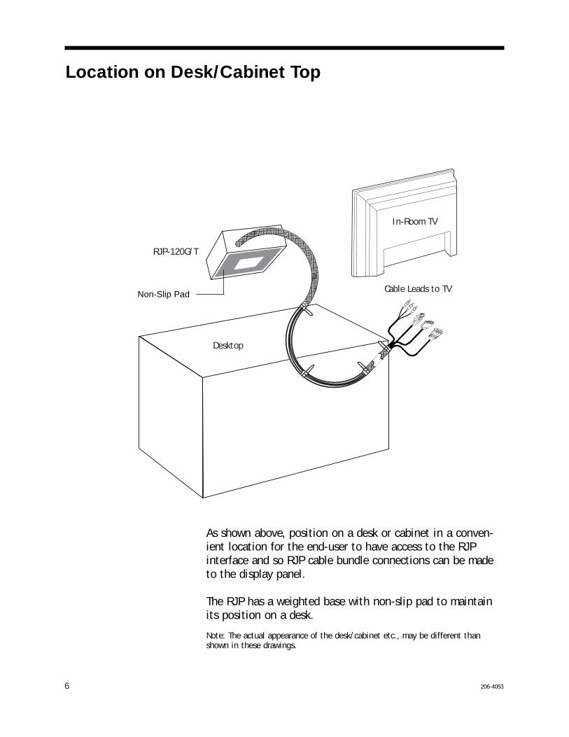
Location on Desk/Cabinet Top
As shown above, position on a desk or cabinet in a conven-ient location for the end-user to have access to the RJPinterface and so RJP cable bundle connections can be madeto the display panel.
The RJP has a weighted base with non-slip pad to maintainits position on a desk.
Note: The actual appearance of the desk/cabinet etc., may be different thanshown in these drawings.
RJP-120G/T
Cable Leads to TV
In-Room TV
Desktop
. . . . . . . .
. . . . . . . .
. . . . . . . .
Non-Slip Pad
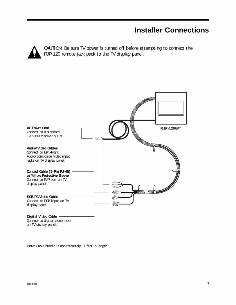
CAUTION: Be sure TV power is turned off before attempting to connect theRJP-120 remote jack pack to the TV display panel.
Installer Connections
7206-4053
. . . . . . . .
. . . . . . . .
. . . . . . . .
RJP-120G/T
Control Cable (8-Pin RJ-45) w/Yellow Protective SleeveConnect to RJP port on TVdisplay panel.
Audio/Video CablesConnect to Left-RightAudio/composite Video inputjacks on TV display panel.
RGB PC Video CableConnect to RGB input on TVdisplay panel.
Digital Video CableConnect to digital video inputon TV display panel.
Note: Cable bundle is approximately 11 feet in length.
AC Power CordConnect to a standard 120V 60Hz power outlet.
DVI/PC AUDIO
INDVI
RS-232C
PC IN
UPDATE
DIGTAL AUDIOOUT (OPTICAL)
RS-232CNORMAL(DTV)
CONTROL
AUDIO IN VIDEO 1 IN
VIDEO 2 INAUDIO IN
M.P.
I.
ANTE
NNA
CA
BLE
RJPINTERFACE FUTURE
USE
AC IN
...............
.........
RJP-110F
. . . . . . . . . . . . . . . .. . . . . . . .
RJP-120G/T
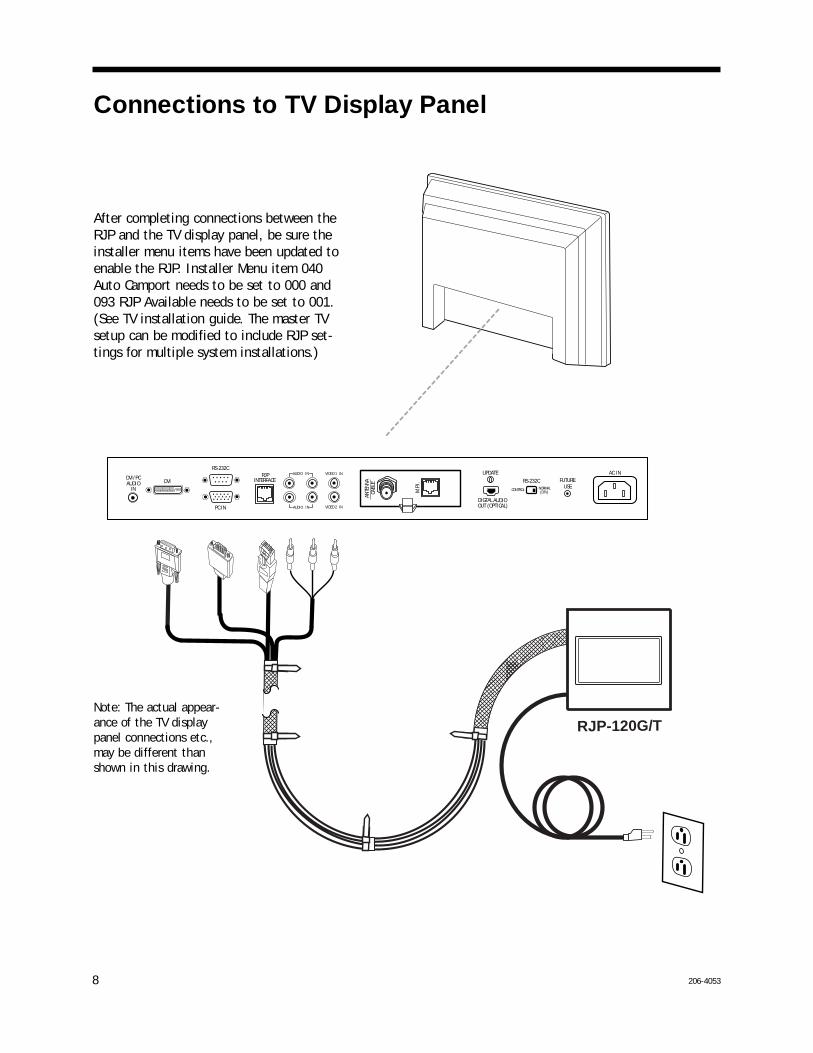
Connections to TV Display Panel
Note: The actual appear-ance of the TV displaypanel connections etc.,may be different thanshown in this drawing.
8 206-4053
After completing connections between theRJP and the TV display panel, be sure theinstaller menu items have been updated toenable the RJP. Installer Menu item 040Auto Camport needs to be set to 000 and093 RJP Available needs to be set to 001.(See TV installation guide. The master TVsetup can be modified to include RJP set-tings for multiple system installations.)
206-4053
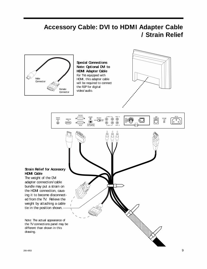
Accessory Cable: DVI to HDMI Adapter Cable/ Strain Relief
...............
.........DVI/PC AUDIO
INHDMI/DVI
IN
RS-232C
PC IN
UPDATE
DIGTAL AUDIOOUT (OPTICAL)
RS-232CNORMAL(DTV)
CONTROL
AUDIO IN VIDEO 1 IN
VIDEO 2 INAUDIO IN
M.P.
I.
ANTE
NNA
CA
BLE
RJPINTERFACE FUTURE
USE
AC IN
Strain Relief for AccessoryHDMI CableThe weight of the DVIadapter connection/cablebundle may put a strain onthe HDMI connection, caus-ing it to become disconnect-ed from the TV. Relieve theweight by attaching a cabletie in the position shown.
Special ConnectionsNote: Optional DVI toHDMI Adapter CableFor TVs equipped withHDMI, this adapter cablewill be required to connectthe RJP for digitalvideo/audio.
MaleConnector
FemaleConnector
Note: The actual appearance ofthe TV connections panel may bedifferent than shown in thisdrawing.
9

1 0 206-4053
End-User Multi-Media Interface Connections
The end-user simply plugs a device such as a laptop computer with the appropriate cables into the RJPconnection panel. The Remote Jack Pack senses the new source connection and switches the TV to thenewly-connected source. The device’s sound and image are then presented on the in-room TV displaypanel. The TV display panel adjusts automatically to the computer output format. When the laptop isdisconnected, the interface directs the TV to revert back to the previous source for video and audio.
The end-user has several audio/video connection options available for connecting external devices. Theguest/user can connect a portable DVD Player, CD Player, Camcorder, MP-3 Player, Notebook Computer,Portable Video Game Player, etc. For added convenience, four AC power outlets are also available onthe sides of the interface to provide power for these external devices and/or recharge laptop or cellphone batteries. (The maximum combined current allowed for the AC power outlets is 7 Amps.)
An end-user could connect and hear audio from one device and connect and view video from a differ-ent device. The RJP offers two different stereo audio input jacks to accommodate various end-userdevices. However, only the higher priority audio source will be selected and heard. Similarly, multiplevideo inputs are available, but only the higher priority video source will be selected and displayed.
(Note: Audio In, Audio In L-R and Video In inputs detect the presence of an inserted plug, regardless if a signal is present or not.)
AUDIO INVIDEO IN AUDIO INL R
PC VIDEO INDIGITAL VIDEO IN
L-R Audio/Video Input JacksConnection for Left-Right Audio/composite Video sources.
PC Video (RGB) Input PortConnection for PC Video.
3.5 mm Stereo Audio Input JackConnection for MP-3 player or PC audio.
Digital Video Input PortConnection for digital video sources. (portable DVD)
7 AMP MAXIMUM CURRENT
PRESS TO RESET
X2
Circuit Breaker for AC OutletsIf the 7 Amp maximum current is
exceeded, the circuit breakeris tripped and AC power isturned off. Remove all ACpower cords and then push
Reset button in to restore AC power.
206-4053-A 1 1
End-User Audio/Video InputPrioritiesNote: The highest priority is listed first.
Audio Inputs/Sources1st. 3.5 mm Stereo Audio Jack2nd. Left - Right Audio Jacks3rd. Digital Video Audio4th. TV Display Panel Tuner Audio (Audio Default)
Video Inputs1st. Digital Video2nd. PC Video3rd. Video Composite Jack4th. TV Display Panel Tuner Video (Video Default)
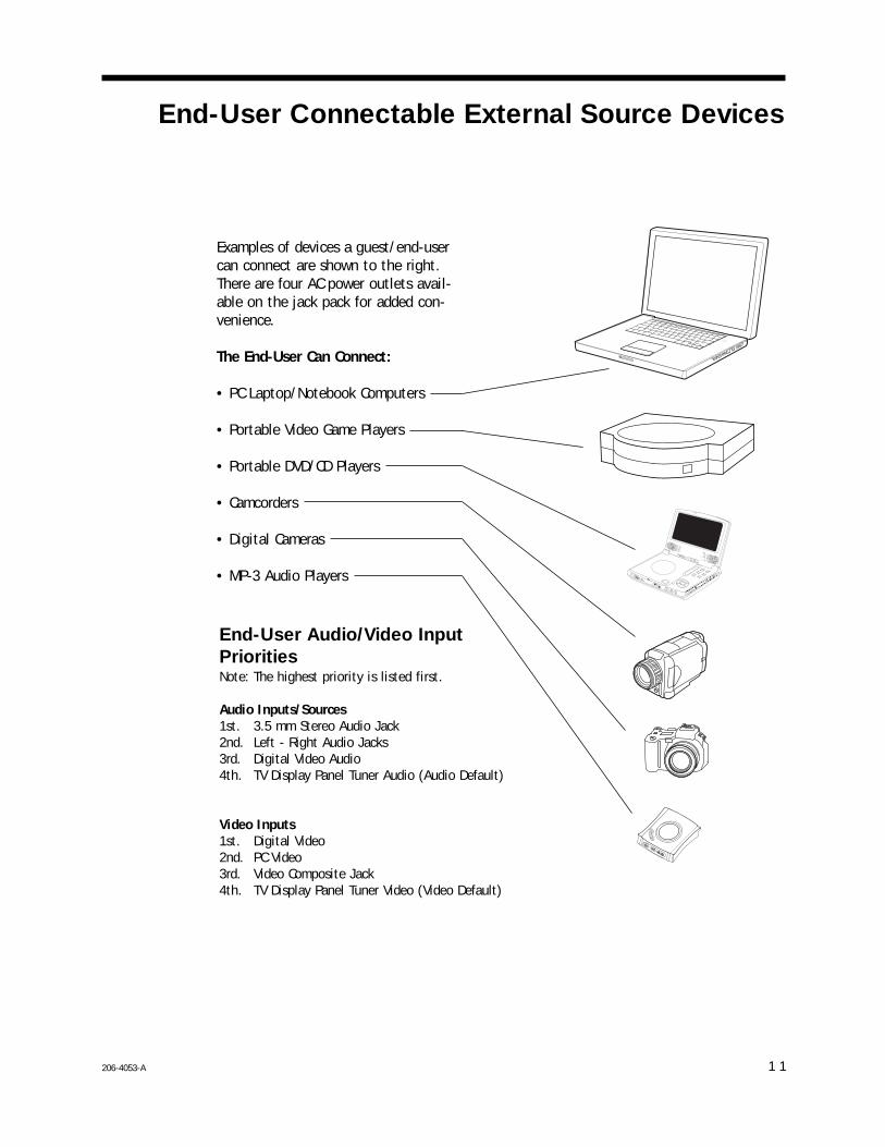
Examples of devices a guest/end-usercan connect are shown to the right.There are four AC power outlets avail-able on the jack pack for added con-venience.
The End-User Can Connect:
• PC Laptop/Notebook Computers
• Portable Video Game Players
• Portable DVD/CD Players
• Camcorders
• Digital Cameras
• MP-3 Audio Players
End-User Connectable External Source Devices

Specifications
206-40531 2
Application Makes available to the hotel’s guests, a multi-media interface to the in-room TV displaypanel. Input jacks are provided for external portable devices such as DVD/CD Players,Laptop Computers, Camcorders, etc.
DimensionsHeight 2.9 Inches ( 73.6 mm)Width 7.6 Inches (193.0 mm)Depth 7.7 Inches (195.6 mm)
Weight 8.5 Pounds (3.85553 kg)
End-User Device InputsAC Outlets x 4 AC 120V 60Hz (Maximum 7 Amps.
total combined current allowed for AC outlets)
Audio In 3.5 mm Stereo Audio Jack
Audio In L-R Left - Right Audio Jacks(Nom In: 250mV RMS @ 22K ohms)Overload In: 1.6V RMS Max
Video In Composite Video Jack 1 Vpp, 75 ohms
PC Video In 15-pin RGB PC Monitor Connector
Digital Video In Digital Video Connector
RegulatoryUL, FCC Class B, Digital Video Device
Environmental ParametersOperating Temperature 0° to 40° Degrees Celsius (32° to 104° Degrees Fahrenheit)
Storage Temperature -20° to 85° Degrees Celsius (-4° to 185° Degrees Fahrenheit)
Cooling Free Air Convection
Humidity 10% to 90% Non-condensing
Supplied Accessories List (Attached Cable Assembly) Note: All cables within cable bundle are 12 feet in length.
• Digital Video Cable• PC Video RGB Cable• Control Cable (8-Pin RJ-45)• 1-Set Left-Right Audio/Video Cables
(Attached Cord) • AC Power Cord, 120V 60Hz (Misc. Hardware) • 1 Black Cable Tie (DVI to HDMI Adapter Cable see page 9.)(Separate Cable) • DVI (F) to HDMI (M) Adapter Cable (Optional connection)
Note: Design and specifications subject to change without prior notice.

Troubleshooting
206-4053
Equipment Setup Analysis Notes• Make sure all connectors and connections are tight and secure on user device, RJP-120 and TV.• Check to assure user device, RJP-120 and TV are all powered up and working properly and that the TV
Installer menu items are set correctly.• Audio and Video can be from different sources. Default is TV tuner Audio and Video, if no other
audio/video source is connected.• Audio source must be viable. The audio output from the customer’s device must be present when connect-
ed to be heard at the TV. • RJP AC circuit breaker maximum is 7 Amps. If the 7 Amp current limit is exceeded, the breaker will trip;
unplug all accessory devices from RJP AC outlets and press RESET on back of unit.
Test Procedures• Test and connect only one user device to determine if RJP is providing audio/video to TV.• Test user device on another RJP (perhaps located in a different room) to determine if user device is com-
patible with RJP.• On LCD or Plasma TV, Installer menu items:
040 Auto Camport needs to be disabled by setting it to 000.093 RJP Available needs to be set to 001 to enable RJP mode.
Following are some possible solutions to problems:
Problem Possible Cause(s) Check RJP, User Device and In-Room TV
No Power • Power not connected? • Circuit breaker on RJP tripped?
(Unplug all accessory devices from RJP AC outlets, press RESET on back of unit.)
No Audio • Have all audio connections been made?• Audio output available?• Volume level turned up?• Sound muted?• TV setup correct for RJP? (Installer menu item 040 is set to 000 and 093 set to 001.)• Try another RJP.• Priority level? (Disconnect other devices.)• Connections made after 040 and 093 menu items set.
(Make connections before adjusting menu items 040 and 093.)
No Video • Video output available?• All video cables connected?• TV setup correct for RJP? (Installer menu item 040 is set to 000 and 093 set to 001.)• Priority level? (Disconnect other devices.)
Poor Video • Check connections. (Video pass-through no user action possible.)
1 3
206-40531 4
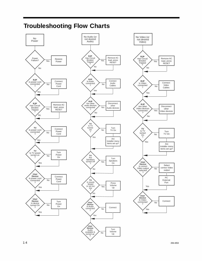
Troubleshooting Flow Charts
NoPower
Yes
No
PowerFailure?
RestorePower
RJPIs power cord
connected?
ConnectPowerCord
TVIs power cord
connected?
ConnectPowerCord
TVIs TV powerturned on
?
TurnPower
On
Yes
No
No
Yes
RJPHas Circuit
BreakerTripped
?
Remove ACload, press
RESET
Yes
No
Yes
No
UserDevice
Is power cordconnected
?
ConnectPowerCord
No
Yes
UserDevice
Is deviceturned On
?
TurnPower
OnNo
Yes
Yes
No
No
Yes
Yes
Yes
RJPHas Circuit
BreakerTripped
?
Yes
No
No
RJPAre other
audio devicesconnected
?
Disconnectother
Audio devices
No Audio (ornot desired
Audio)
RJPIs Audio
connected?
TVAre
Speakersturned Off
?
TurnSpeakers
On
ConnectAudioCables
TVIs soundMuted
or set toolow?
PressVolume
Up
No
No
Yes
UserDeviceAudio
available &turned up
?
TurnVolume
Up
UserDeviceIs Audio
connected?
Connect
Yes
No
TVIs TV
turned On?
TurnTV On
AreInstaller menuitems set up?
No
Remove ACload, press
RESET
Yes
No
Yes
No
Yes
RJPHas Circuit
BreakerTripped
?
Yes
No
No
RJPAre other
Video devicesconnected
?
Disconnectother
Video devices
No
UserDevice
Is correctVideo output
selected?
Selectcorrect Video
output
No
Yes
No Video (or not desired
Video)
RJPIs Video
connected?
TVIs TVturned
On?
TurnTV On
ConnectVideo
Cables
UserDeviceIs Video
connected?
Connect
AreInstaller menuitems set up?
Yes
PCExternal
Port
Remove ACload, press
RESET
206-4053 1 5
Quick Setup Reference Guide
RJP-120G/T
Cable Leads to TV
In-Room TV
Desktop
. . . . . . . .
. . . . . . . .
. . . . . . . .
DVI/PC AUDIO
INDVI
RS-232C
PC IN
UPDATE
DIGTAL AUDIOOUT (OPTICAL)
RS-232CNORMAL(DTV)
CONTROL
AUDIO IN VIDEO 1 IN
VIDEO 2 INAUDIO IN
M.P.
I.
ANTE
NNA
CA
BLE
RJPINTERFACE FUTURE
USE
AC IN
...............
.........
RJP-110F
. . . . . . . . . . . . . . . .. . . . . . . .
RJP-120G/T
RJP-110F Remote Jack Pack (See other s
ide)
• An e
xample
of usa
ge woul
d be t
o have
your
cell ph
one an
d PC com
puter p
lugged
into
the AC
outlet
s recha
rging w
hile yo
u liste
n to a
CD pla
yer an
d watc
h the
stock
report
on TV
.
Or, liste
n to t
he hot
el ente
rtainm
ent ne
twork an
d use
your p
ersona
l PC co
mputer.
• You
can co
nnect y
our po
rtable
DVD/CD Pla
yer, Ca
mcorder
, MP-3
Player
, Lapto
p PC, V
ideo
Game P
layer o
r othe
r pers
onal en
tertain
ment de
vices
like yo
ur cel
l phone
.
®
PC
Game
Machine
DVD
Player
Camcorder
MP3
Player
Digital
Camera
1.
2.
3.
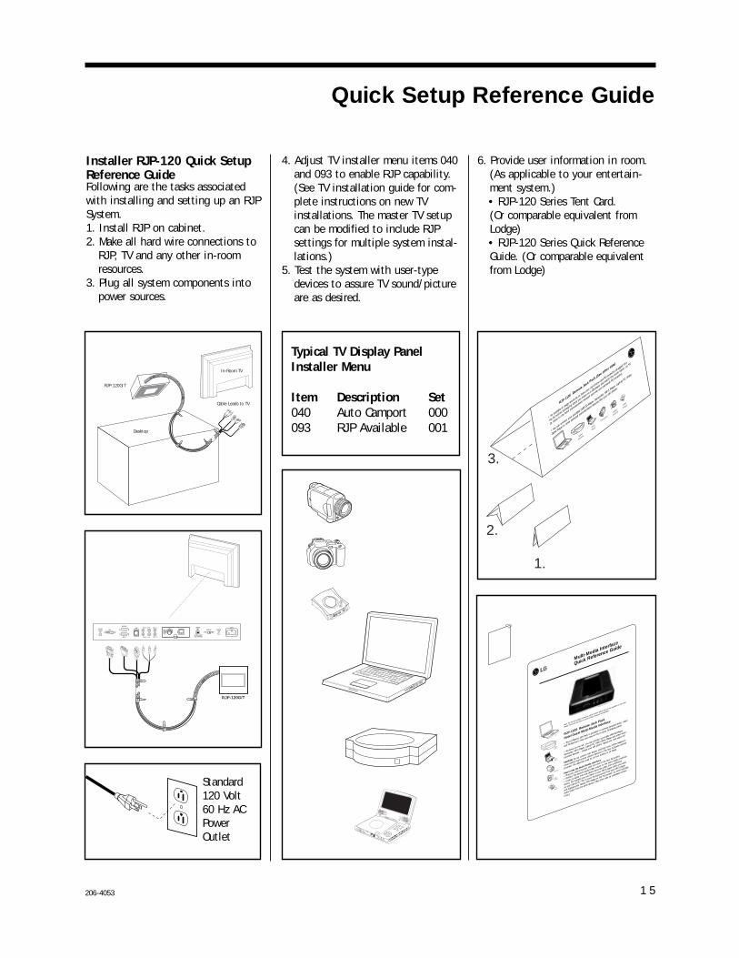
Typical TV Display PanelInstaller Menu
Item Description Set040 Auto Camport 000093 RJP Available 001
RJP-110S Remote Jack Pack
Hotel Guest Multi-Media Interface
• The LG Remote Jack Pa
ck is provided to connect p
ersonal audio, video
and PC devices to hear a
nd view on the in-room TV/display p
anel.
• As shown on the left, you can connect a
portable DVD/CD Player,
Camcorder, MP-3 Player
, Laptop PC, Video Game Player
and other enter-
tainment devices -- c
harge your cell phone, lap
top etc. and watch TV.
CAUTION: Do not connect hair d
ryers, clothing irons, co
ffee makers
or
other similar h
igh-current electric
devices to the four AC power outlets
provided. The maximum load for all
four outlets is 10 Amps.
How to Use the Multi-Media Interface
• Plug your device’s power co
rd into one of the four AC outlets.
• Connect the device
’s audio/video output to the multi-m
edia interfa
ce.
• Listen to audio from one device
and view video from a differe
nt
device. For exa
mple you can liste
n to your MP-3 player while yo
u work
on your laptop PC. Th
e in-room TV plays sound from your MP-3 player
and displays your lap
top PC’s image on the TV’s scr
een. Or, more typically
audio/video from the same device
. (See other sid
e for available co
nnec-
tions.)
PC
Game
Machine
DVD
Player
Camcorder
MP3
Player
Digital
Camera
Multi-Media Interface
Quick Reference Guide
Note: All the multi-m
edia connectio
n options shown above may not be ava
ilable at this hotel.
Please check w
ith the hotel to confirm what re
sources are a
vailable.
Standard120 Volt60 Hz ACPowerOutlet
Installer RJP-120 Quick SetupReference GuideFollowing are the tasks associatedwith installing and setting up an RJPSystem.1. Install RJP on cabinet.2. Make all hard wire connections to
RJP, TV and any other in-roomresources.
3. Plug all system components intopower sources.
4. Adjust TV installer menu items 040and 093 to enable RJP capability. (See TV installation guide for com-plete instructions on new TVinstallations. The master TV setupcan be modified to include RJPsettings for multiple system instal-lations.)
5. Test the system with user-typedevices to assure TV sound/pictureare as desired.
6. Provide user information in room.(As applicable to your entertain-ment system.)• RJP-120 Series Tent Card. (Or comparable equivalent fromLodge)• RJP-120 Series Quick ReferenceGuide. (Or comparable equivalentfrom Lodge)

LG Electronics U.S.A., Inc.2000 Millbrook Drive, Lincolnshire, IL 60069
206-4089Issue*
Remote Jack Pack Welcome to the LG family! We believe that you will be pleased with your new LG product.Please read this warranty carefully, it is a “LIMITED WARRANTY” as defined under Federal Law.This warranty gives you specific legal rights, and you may also have other rights that varyfrom state-to-state within the U.S.A.
LG’S RESPONSIBILITY
Service Labor During a period of one year from effective warranty date, LG will replace a defective unit, asdetermined by the LG service center, as a result of manufacturing defects.
Replacement New or remanufactured replacements for factory-defective units will be supplied by an LGauthorized service center for one year from effective warranty date. Such replacement unit iswarranted for the remaining portion of the original warranty period.
Warranty Service Warranty service is provided. Call 1-888-865-3026 for further information.
Not Covered This warranty covers manufacturing defects and does not cover installation, adjustment ofcustomer controls, installation or repair of antenna systems, cable converters or cable compa-ny-supplied equipment; it also does not cover damage due to misuse, abuse, negligence, actsof God or other causes beyond the control of LG. Any alteration of the product after manufac-ture voids this warranty in its entirety.THIS WARRANTY IS IN LIEU OF ANY OTHER WARRANTY, EXPRESS OR IMPLIED, INCLUDINGWITHOUT LIMITATION, ANY WARRANTY OF MERCHANTABILITY OR FITNESS FOR A PARTICU-LAR PURPOSE, AND LG SHALL NOT BE LIABLE FOR ANY CONSEQUENTIAL, INDIRECT, ORINCIDENTAL DAMAGES OF ANY KIND, INCLUDING LOST REVENUES OR PROFITS IN CONNEC-TION WITH THIS PRODUCT. SOME STATES DO NOT ALLOW LIMITATIONS ON HOW LONG ANIMPLIED WARRANTY LASTS OR THE EXCLUSION OR LIMITATION OF INCIDENTAL OR CONSE-QUENTIAL DAMAGES, SO THE ABOVE LIMITATIONS OR EXCLUSIONS MAY NOT APPLY TOYOU.
OWNER’S RESPONSIBILITY
Effective Warranty begins on the date of installation of the RJP-120 Multi-Media Interface. Warranty Date For your convenience, keep the dealer’s dated bill of sale or delivery ticket as evidence
of the purchase date.Installation Read the Installation and Setup Guide carefully so that you will understand the functions of
Guide the RJP-120 and how to make adjustments.Antenna Reception problems caused by inadequate antenna or faulty antenna connections are the
owner’s responsibility.Audio Output Audio problems caused by inadequate audio devices or audio material with sound level lapses
are not within the control of LG and therefore are the owner’s responsibility.Warranty Service For warranty service information, call 1-888-865-3026.
- A replacement unit that is LG’s responsibility (see above) will be provided without charge.Other service is at the owner’s expense. - If you have any problem in obtaining satisfactory warranty service, call 1-888-865-3026.- You must provide the model number, serial number and date of purchase or date of originalinstallation. - Before you ask for warranty service, reread this guide. You might avoid a service call.
For Customer Support/Service please call: 1-888-865-3026
www.lgcommercial.com
LG RJP-120G/T Warranty